Assembly instructions for electronic on-board starters - FEMA ...
Assembly instructions for electronic on-board starters - FEMA ...
Assembly instructions for electronic on-board starters - FEMA ...

Create successful ePaper yourself
Turn your PDF publications into a flip-book with our unique Google optimized e-Paper software.
<str<strong>on</strong>g>Assembly</str<strong>on</strong>g> <str<strong>on</strong>g>instructi<strong>on</strong>s</str<strong>on</strong>g> <str<strong>on</strong>g>for</str<strong>on</strong>g> <str<strong>on</strong>g>electr<strong>on</strong>ic</str<strong>on</strong>g> <strong>on</strong>-<strong>board</strong> starter<br />
Additi<strong>on</strong>al assembly <str<strong>on</strong>g>instructi<strong>on</strong>s</str<strong>on</strong>g> <str<strong>on</strong>g>for</str<strong>on</strong>g> OS-Max<br />
FT 160 »Gemini«<br />
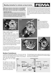
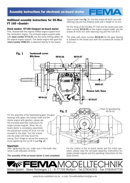
Stock number 9710A Compact <strong>on</strong>-<strong>board</strong> starter<br />
First, disassemble the original OSMax engine support from<br />
the combusti<strong>on</strong> engine. The enclosed engine support plate<br />
with stock number 9710-01 has the same drilling pattern as<br />
the original engine support. The starter engine with gear-box<br />
(stock number 9580-01) is attached directly to the engine<br />
For the assembly of the freewheeling gear, the gear<br />
bearings with gears, the Cardan shaft and the<br />
starter engine with gearbox, please see<br />
the enclosed assembly <str<strong>on</strong>g>instructi<strong>on</strong>s</str<strong>on</strong>g> <str<strong>on</strong>g>for</str<strong>on</strong>g><br />
single cylinder engines. When the <strong>on</strong><strong>board</strong><br />
starter is completely assembled,<br />
the adjustment screws M 3x16 mm are<br />
screwed to the plate. Turn the screws<br />
into the plate until they touch the<br />
casing. D<strong>on</strong>’t <str<strong>on</strong>g>for</str<strong>on</strong>g>get to secure the screws by<br />
fi rmly tightening the nut M 3 (see Fig. 2).<br />
Important:<br />
After tightening the nut, make sure if the tooth tolerance<br />
is still adjusted correctly.<br />
The assembly of the <strong>on</strong>-<strong>board</strong> starter is now completed.<br />
support plate (see Fig. 1). Use the screws M 4x25 mm with<br />
retaining ring and the distance bolts with a length of 16 mm.<br />
For the fi xing of the OS-Max FT-160 and the dowel pins with<br />
stock number 9518-05 <strong>on</strong> the engine support plate, use the<br />
screws M 4x30 mm with retaining ring and the nuts M 4.<br />
The plate with stock number 9518-03 <str<strong>on</strong>g>for</str<strong>on</strong>g> the gear bearing<br />
is screwed to the dowel pins with the countersunk screws M<br />
5x16 mm.<br />
www.fema-modelltechnik.de · e-mail: FemaModelltechnik@gmx.de<br />
- 1 -<br />
Plate <str<strong>on</strong>g>for</str<strong>on</strong>g> gearbearing<br />
9518-03<br />
Adjusting screw<br />
For the c<strong>on</strong>trol of the <strong>on</strong>-<strong>board</strong> starter and the initial operati<strong>on</strong>,<br />
please read the enclosed assembly <str<strong>on</strong>g>instructi<strong>on</strong>s</str<strong>on</strong>g> <str<strong>on</strong>g>for</str<strong>on</strong>g><br />
single cylinder engines and the operating <str<strong>on</strong>g>instructi<strong>on</strong>s</str<strong>on</strong>g> <str<strong>on</strong>g>for</str<strong>on</strong>g> the<br />
Glow-C<strong>on</strong>trol.<br />
Böhler GmbH · Obere Rebbergstr.11 · D-77709 Wolfach · Tel.07834/303 · Fax 07834/47735