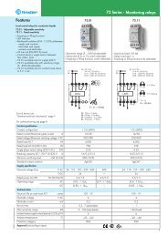
Features 71 Series - Monitoring relays 10 A - Finder
Features 71 Series - Monitoring relays 10 A - Finder
Features 71 Series - Monitoring relays 10 A - Finder

You also want an ePaper? Increase the reach of your titles
YUMPU automatically turns print PDFs into web optimized ePapers that Google loves.
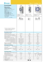
XI-2012, www.findernet.com<br />
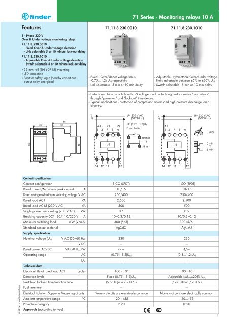
<strong>Features</strong><br />
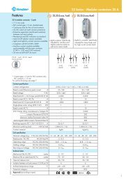
1 - Phase 230 V<br />
Over & Under voltage monitoring <strong>relays</strong><br />
<strong>71</strong>.11.8.230.00<strong>10</strong><br />
- Fixed Over & Under voltage detection<br />
- Link selectable 5 or <strong>10</strong> minute lock-out delay<br />
<strong>71</strong>.11.8.230.<strong>10</strong><strong>10</strong><br />
- Adjustable Over & Under voltage detection<br />
- Switch selectable 5 or <strong>10</strong> minute lock-out delay<br />
• 35 mm rail (EN 60<strong>71</strong>5) mounting<br />
• LED indication<br />
• Positive safety logic (healthy conditions -<br />
output relay energised)<br />
Contact specification<br />
Contact configuration<br />
Rated current/Maximum peak current A<br />
Rated voltage/Maximum switching voltage V AC<br />
Rated load AC1 VA<br />
Rated load AC15 (230 V AC) VA<br />
Single phase motor rating (230 V AC) kW<br />
Breaking capacity DC1: 30/1<strong>10</strong>/220 V A<br />
Minimum switching load mW (V/mA)<br />
Standard contact material<br />
Supply specification<br />
Nominal voltage (UN) V AC (50/60 Hz)<br />
V DC<br />
Rated power AC/DC VA (50 Hz)/W<br />
Operating range AC<br />
DC<br />
Technical data<br />
Electrical life at rated load AC1 cycles<br />
Detection levels<br />
Switch-on lock-out time/reaction time<br />
Fault memory<br />
Electrical isolation: Supply to Measuring circuits<br />
Ambient temperature range °C<br />
Protection category<br />
Approvals (according to type)<br />
<strong>71</strong>.11.8.230.00<strong>10</strong> <strong>71</strong>.11.8.230.<strong>10</strong><strong>10</strong><br />
• Fixed - Over/Under voltage limits,<br />
(0.75...1.2) U N respectivity<br />
• Link selectable - 5 min or <strong>10</strong> min delay<br />
1 CO (SPDT) 1 CO (SPDT)<br />
<strong>10</strong>/15 <strong>10</strong>/15<br />
250/400 250/400<br />
2,500 2,500<br />
500 500<br />
0.5 0.5<br />
<strong>10</strong>/0.3/0.12 <strong>10</strong>/0.3/0.12<br />
300 (5/5) 300 (5/5)<br />
AgCdO AgCdO<br />
230 230<br />
— —<br />
4/— 4/—<br />
(0.75...1.2)UN (0.8...1.2)UN — —<br />
<strong>10</strong>0 · <strong>10</strong> 3<br />
Fixed (0.75…1.2)U N<br />
<strong>71</strong> <strong>Series</strong> - <strong>Monitoring</strong> <strong>relays</strong> <strong>10</strong> A<br />
• Adjustable - symmetrical Over/Under voltage<br />
limits adjustable between ±5% to ±20% U N<br />
• Switch selectable - 5 min or <strong>10</strong> min delay<br />
• Detects and trips on out-of-limits L-N voltage, and protects against excessive “starts/hour”<br />
through ”power-on” and “lock-out” time delays.<br />
• Typical applications - protection of compressor motors and high pressure discharge lamp<br />
circuitry.<br />
Fixed limits<br />
<strong>10</strong>0 · <strong>10</strong> 3<br />
Adjustable (±5…±20)% U N<br />
(5 or <strong>10</strong>)min / < 0.5 s (5 or <strong>10</strong>)min / < 0.5 s<br />
— —<br />
None – circuits are electrically common None – circuits are electrically common<br />
–20...+55 –20...+55<br />
IP 20 IP 20<br />
1
<strong>Features</strong><br />
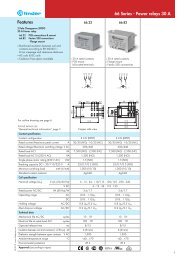
3 - Phase 400 V<br />
Over & Under voltage monitoring relay<br />
<strong>71</strong>.31.8.400.<strong>10</strong><strong>10</strong><br />
- Adjustable Over & Under voltage detection<br />
- Switch selectable 5 or <strong>10</strong> minute lock-out delay<br />
• 35 mm rail (EN 60<strong>71</strong>5) mounting<br />
• LED indication<br />
• Positive safety logic (healthy conditions -<br />
output relay energised)<br />
Contact specification<br />
Contact configuration<br />
Rated current/Maximum peak current A<br />
Rated voltage/Maximum switching voltage V AC<br />
Rated load AC1 VA<br />
Rated load AC15 (230 V AC) VA<br />
Single phase motor rating (230 V AC) kW<br />
Breaking capacity DC1: 30/1<strong>10</strong>/220 V A<br />
Minimum switching load mW (V/mA)<br />
Standard contact material<br />
Supply specification<br />
Nominal voltage (UN) V AC (50/60 Hz)<br />
V DC<br />
Rated power AC/DC VA (50 Hz)/W<br />
Operating range AC<br />
DC<br />
Technical data<br />
Electrical life at rated load AC1 cycles<br />
Detection levels V (50/60 Hz)<br />
Switch-on lock-out time/reaction time<br />
Fault memory<br />
Electrical isolation: Supply to Measuring circuits<br />
Ambient temperature range °C<br />
Protection category<br />
Approvals (according to type)<br />
2<br />
<strong>71</strong>.31.8.400.<strong>10</strong><strong>10</strong><br />
• Adjustable - symmetrical Over/Under voltage<br />
limits adjustable between ±5% to ±20% U N<br />
• Switch selectable - 5 min or <strong>10</strong> min delay<br />
• Delects and trips on out-of-limits L-L voltage,<br />
and protects against excessive “starts/hour”<br />
through “power-on” and “lock-out” time delays.<br />
• Typical applications - protection of compressor<br />
motors and high pressure discharge lamp<br />
circuitry.<br />
1 CO (SPDT)<br />
<strong>10</strong>/15<br />
250/400<br />
2,500<br />
500<br />
0.5<br />
<strong>10</strong>/0.3/0.12<br />
300 (5/5)<br />
AgCdO<br />
400<br />
—<br />
4/—<br />
(0.8…1.2)UN —<br />
<strong>10</strong>0 · <strong>10</strong> 3<br />
Adjustable (±5...±20)% U N<br />
(5 or <strong>10</strong>)min / < 0.5 s<br />
—<br />
None – circuits are electrically common<br />
–20...+55<br />
IP 20<br />
<strong>71</strong> <strong>Series</strong> - <strong>Monitoring</strong> <strong>relays</strong> <strong>10</strong> A<br />
XI-2012, www.findernet.com
XI-2012, www.findernet.com<br />
<strong>Features</strong><br />
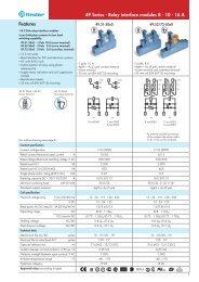
3 - Phase 400 V - Line monitoring <strong>relays</strong><br />
<strong>71</strong>.31.8.400.<strong>10</strong>21<br />
- Over & Under voltage trip on-delay<br />
- Fault memory<br />
<strong>71</strong>.31.8.400.2000<br />
- Phase asymmetry<br />
- Phase rotation<br />
- Phase loss<br />
• 35 mm rail (EN 60<strong>71</strong>5) mounting<br />
• LED indication<br />
• Positive safety logic (healthy conditions -<br />
output relay energised)<br />
Contact specification<br />
Contact configuration<br />
Rated current/Maximum peak current A<br />
Rated voltage/Maximum switching voltage V AC<br />
Rated load AC1 VA<br />
Rated load AC15 (230 V AC) VA<br />
Single phase motor rating (230 V AC) kW<br />
Breaking capacity DC1: 30/1<strong>10</strong>/220 V A<br />
Minimum switching load mW (V/mA)<br />
Standard contact material<br />
Supply specification<br />
Nominal voltage (UN) V AC (50/60 Hz)<br />
V DC<br />
Rated power AC/DC VA (50 Hz)/W<br />
Operating range AC<br />
DC<br />
Technical data<br />
Electrical life at rated load AC1 cycles<br />
Detection level Umin/Umax/Asymmetry Trip on-delay/reaction time<br />
Fault memory - selectable<br />
Electrical isolation: Supply to Measuring circuits<br />
Ambient temperature range °C<br />
Protection category<br />
Approvals (according to type)<br />
• 3 phase 400 V - line voltage monitoring<br />
• Detects over and under voltage<br />
• Adjustable trip on-delay<br />
• Switch selectable fault memory<br />
• Under voltage trip level (0.8...0.95)U N -<br />
Adjustable<br />
• Over voltage trip level 1.15 U N - Fixed<br />
• Trip delay time (0.1…12)s adjustable<br />
• Fault memory, switch selectable<br />
• Fault acknowledgement by switch manipulation<br />
from ON to OFF and back to ON or power<br />
down<br />
L1<br />
L2<br />
L3<br />
A1 A2 A3<br />
1 3 5 7 9<br />
3~U ASY<br />
2 4 6 8 <strong>10</strong><br />
14 12 11<br />
1 CO (SPDT) 1 CO (SPDT)<br />
<strong>10</strong>/15 <strong>10</strong>/15<br />
250/400 250/400<br />
2,500 2,500<br />
500 500<br />
0.5 0.5<br />
<strong>10</strong>/0.3/0.12 <strong>10</strong>/0.3/0.12<br />
300 (5/5) 300 (5/5)<br />
AgCdO AgCdO<br />
400 400<br />
— —<br />
4/ — 4/—<br />
(0.8…1.15)UN (0.8...1.15)UN — —<br />
<strong>10</strong>0 · <strong>10</strong> 3<br />
<strong>71</strong> <strong>Series</strong> - <strong>Monitoring</strong> <strong>relays</strong> <strong>10</strong> A<br />
<strong>71</strong>.31.8.400.<strong>10</strong>21 <strong>71</strong>.31.8.400.2000<br />
• 3 phase asymmetry monitoring<br />
• Phase rotation monitoring<br />
• Phase loss monitoring<br />
• Asymmetry between phases (–5… –20)% UN adjustable<br />
• Detection of the supply voltage<br />
U to A1 (1) and/or A2 (5) > 1.11 UN <strong>10</strong>0 · <strong>10</strong> 3<br />
U= 400 V AC 3~<br />
(50/60 Hz )<br />
(0.8...0.95)U N / 1.15 U N /— 0.8 U N / 1.11 U N /(–5...–20)% U N<br />
(0.1...12)s / < 0.5 s — / < 0.5 s<br />
Yes —<br />
None – circuits are electrically common None – circuits are electrically common<br />
–20...+55 –20...+55<br />
IP 20 IP 20<br />
3
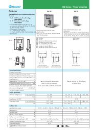
<strong>Features</strong><br />
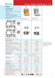
Universal voltage or current detecting and<br />
monitoring relay<br />
<strong>71</strong>.41.8.230.<strong>10</strong>21 - Voltage monitoring<br />
<strong>71</strong>.51.8.230.<strong>10</strong>21 - Current monitoring<br />
• Zero voltage memory according to<br />
EN 60204-7-5<br />
• Programmable for DC or AC detection level:<br />
- range detecting: upper and lower value<br />
- upper set point minus hysteresis range<br />
(5...50)% for switch on<br />
- lower set point plus hysteresis range<br />
(5...50)% for switch on<br />
• Fault memory<br />
• Electrical isolation between measuring<br />
and supply circuits<br />
• Immune to supply interruptions of < 200 ms<br />
• Wide detecting range:<br />
- voltage: DC (15...700)V, AC (15...480)V<br />
• 35 mm rail (EN 60<strong>71</strong>5) mounting<br />
Contact specification<br />
Contact configuration<br />
Rated current/Maximum peak current A<br />
Rated voltage/Maximum switching voltage V AC<br />
Rated load AC1 VA<br />
Rated load AC15 (230 V AC) VA<br />
Single phase motor rating (230 V AC) kW<br />
Breaking capacity DC1: 30/1<strong>10</strong>/220 V A<br />
Minimum switching load mW (V/mA)<br />
Standard contact material<br />
Supply specification<br />
Nominal voltage (UN) V AC (50/60 Hz)<br />
V DC<br />
Rated power AC/DC VA (50 Hz)/W<br />
Operating range AC<br />
DC<br />
Technical data<br />
Electrical life at rated load AC1 cycles<br />
Detection levels AC(50/60 Hz)/DC<br />
Switch-off/reaction/Start delay<br />
Switch-on level of the detecting level %<br />
Fault memory - programmable<br />
Electrical isolation: Supply to Measuring circuits<br />
Ambient temperature range °C<br />
Protection category<br />
Approvals (according to type)<br />
4<br />
• Programmable universal voltage monitoring<br />
relay<br />
• AC/DC voltage detection - adjustable<br />
• AC (50/60 Hz) (15…480)V<br />
• DC (15...700)V<br />
• Switch-on hysteresis (5…50)%<br />
• Switch-off delay (0.1…12)s<br />
• Programmable universal current monitoring relay<br />
• Usable with current transformer 50/5, <strong>10</strong>0/5,<br />
150/5, 250/5, 300/5, 400/5 or 600/5<br />
1 CO (SPDT) 1 CO (SPDT)<br />
<strong>10</strong>/15 <strong>10</strong>/15<br />
250/400 250/400<br />
2,500 2,500<br />
500 500<br />
0.5 0.5<br />
<strong>10</strong>/0.3/0.12 <strong>10</strong>/0.3/0.12<br />
300 (5/5) 300 (5/5)<br />
AgCdO AgCdO<br />
230 230<br />
— —<br />
4 / — 4 / —<br />
(0.85...1.15)UN (0.85...1.15)UN — —<br />
<strong>10</strong>0 · <strong>10</strong> 3<br />
<strong>71</strong> <strong>Series</strong> - <strong>Monitoring</strong> <strong>relays</strong> <strong>10</strong> A<br />
<strong>71</strong>.41.8.230.<strong>10</strong>21 <strong>71</strong>.51.8.230.<strong>10</strong>21<br />
• AC/DC current detection - adjustable<br />
• AC(50/60Hz) (0.1...<strong>10</strong>)A with current<br />
transformer to 600A<br />
• DC (0.1...<strong>10</strong>)A<br />
• Switch-on hysteresis (5...50)%<br />
• Switch-off delay (0.1…12)s<br />
• Start delay (0.1…20)s<br />
programmable programmable<br />
<strong>10</strong>0 · <strong>10</strong> 3<br />
(15...480)V/(15...700)V (0.1…<strong>10</strong>)A at transducer to 600A / (0.1…<strong>10</strong>)A<br />
(0.1…12)s / < 0.35 s / < 0.5 s (0.1…12)s / < 0.35 s / (0.1…20)s<br />
5…50 5…50<br />
Yes Yes<br />
Yes Yes<br />
–20…+55 –20…+55<br />
IP 20 IP 20<br />
XI-2012, www.findernet.com
XI-2012, www.findernet.com<br />
<strong>Features</strong><br />
Thermistor temperature sensing <strong>relays</strong> for<br />
industrial applications<br />
<strong>71</strong>.91 - 1 Pole, without fault memory<br />
<strong>71</strong>.92 - 2 Pole, with fault memory<br />
• Overload protection according EN 60204-7-3<br />
• Positive safety logic - make contact opens if the<br />
measured value is outside of the acceptable range<br />
• Industry standard module<br />
• LED status indication<br />
• 35 mm rail (EN 60<strong>71</strong>5) mounting<br />
<strong>71</strong>.91<br />
<strong>71</strong>.92<br />
Contact specification<br />
Contact configuration<br />
Rated current/Maximum peak current A<br />
Rated voltage/Maximum switching voltage V AC<br />
Rated load AC1 VA<br />
Rated load AC15 (230 V AC) VA<br />
Single phase motor rating (230 V AC) kW<br />
Breaking capacity DC1: 30/1<strong>10</strong>/220 V A<br />
Minimum switching load mW (V/mA)<br />
Standard contact material<br />
Supply specification<br />
Nominal voltage (UN) V AC (50/60 Hz)<br />
V AC/DC<br />
Rated power AC/DC VA (50 Hz)/W<br />
Operating range AC<br />
DC<br />
Technical data<br />
Electrical life at rated load AC1 cycles<br />
PTC detecting: Short circuit/Temperature OK<br />
Reset/PTC break<br />
Delay time/activaction time<br />
Fault memory - switch selectable<br />
Electrical isolation: Supply to Measuring circuits<br />
Ambient temperature range °C<br />
Protection category<br />
Approvals (according to type)<br />
<strong>71</strong>.91.x.xxx.0300 <strong>71</strong>.92.x.xxx.0001<br />
• Thermistor relay<br />
• 1 Pole normally open contact<br />
• 24 V AC/DC, or 230 V AC supply<br />
• Temperature detection with PTC<br />
• PTC short circuit detection<br />
• PTC wire breakage detection<br />
1 NO (SPST-NO) 2 CO (DPDT)<br />
<strong>10</strong>/15 <strong>10</strong>/15<br />
250/400 250/400<br />
2,500 2,500<br />
500 500<br />
0.5 0.5<br />
<strong>10</strong>/0.3/0.12 <strong>10</strong>/0.3/0.12<br />
300 (5/5) 300 (5/5)<br />
AgCdO AgCdO<br />
230 230<br />
24 24<br />
1/0.5 1/0.5<br />
(0.85...1.15)UN (0.85...1.15)UN — —<br />
<strong>10</strong>0 · <strong>10</strong> 3<br />
<strong>71</strong> <strong>Series</strong> - <strong>Monitoring</strong> <strong>relays</strong> <strong>10</strong> A<br />
• Thermistor relay with fault memory<br />
• 2 Pole changeover contacts<br />
• 24 V AC/DC, or 230 V AC supply<br />
• Temperature detection with PTC<br />
• Fault memory – switch selectable<br />
• Reset by Reset button or supply interruption<br />
• PTC short circuit detection<br />
• PTC wire breakage detection<br />
<strong>10</strong>0 · <strong>10</strong> 3<br />
20 Ω ...
Ordering information<br />
Example: Universal voltage monitoring relay with LCD display for AC/DC voltage detection, 1 CO (SPDT) contact rated <strong>10</strong> A 250,<br />
supply voltage 230 V, programmable delay time and fault memory.<br />
<strong>Series</strong><br />
Type<br />
1 = 1 phase AC line monitoring<br />
3 = 3 phase AC line monitoring<br />
4 = AC/DC universal- Voltage detection<br />
5 = AC/DC universal- Current detection<br />
9 = Thermistor relay (temperature<br />
monitoring with PTC thermistor)<br />
No. of poles<br />
1 = 1 CO (SPDT) types <strong>71</strong>.11, 31, 41, 51<br />
1 = 1 NO (SPST-NO) type <strong>71</strong>.91<br />
2 = 2 CO (DPDT) type <strong>71</strong>.92<br />
Supply version<br />
0 = AC(50/60Hz)/DC<br />
8 = AC (50/60 Hz)<br />
Supply voltage<br />
024 = 24 V AC/DC<br />
230 = 230 V<br />
400 = 400 V<br />
Additional functions<br />
0 = Basic function<br />
1 = Adjustable detection value<br />
2 = Adjustable: Asymmetry, phase loss, phase rotation<br />
6<br />
7 1<br />
. 4 1 . 8 . 2 3 0 . 1 0 2 1<br />
<strong>71</strong> <strong>Series</strong> - <strong>Monitoring</strong> <strong>relays</strong> <strong>10</strong> A<br />
Special versions<br />
0 = No fault memory<br />
1 = Fault memory<br />
Options<br />
0 = No delay time<br />
1 = Two selectable delay times<br />
2 = Adjustable delay times<br />
Contact circuit<br />
0 = CO (nPDT)<br />
3 = NO (nPST-NO)<br />
XI-2012, www.findernet.com
XI-2012, www.findernet.com<br />
Technical data<br />
Insulation<br />
<strong>71</strong> <strong>Series</strong> - <strong>Monitoring</strong> <strong>relays</strong> <strong>10</strong> A<br />
Insulation according to EN 618<strong>10</strong>-1 insulation rated voltage V 250<br />
Dielectric strength (A1, A2, A3, B1, B2), and V AC 2,500<br />
contact terminals (11, 12, 14) and terminals (Z1, Z2) kV (1.2/50 μs) 6<br />
Dielectric strength at open contact<br />
EMC specifications<br />
V AC 1,000<br />
Type of test Reference Standard<br />
rated impulse withstand voltage kV 4<br />
pollution degree 3<br />
over-voltage category III<br />
Electrostatic discharge contact discharge EN 6<strong>10</strong>004-2 8 kV<br />
air discharge EN 6<strong>10</strong>004-2 8 kV<br />
Radio-frequency electromagnetic field (80…1,000)MHz EN 6<strong>10</strong>004-3 3 V/m<br />
Fast transients (burst) (5-50 ns, 5 kHz) on (A1, A2, A3, B1, B2) and (Z1, Z2) EN 6<strong>10</strong>004-4 2 kV<br />
Surges (1.2/50 μs) on (A1, A2, A3, B1, B2) and (Z1, Z2) common mode EN 6<strong>10</strong>004-5 4 kV<br />
differential mode EN 6<strong>10</strong>004-5 4 kV<br />
Radio-frequency common mode (0.15 ÷ 80 MHz) to A1 - A2 EN 6<strong>10</strong>004-6 <strong>10</strong> V<br />
Radiated and conducted emission<br />
Other data<br />
EN 55022 class B<br />
Voltage and current values at terminals Z1 Z2 Type <strong>71</strong>.11 Link for time range V / mA 230 V / —<br />
Type <strong>71</strong>.91, <strong>71</strong>.92 PTC temperature measurement V / mA 24 V / 2.4<br />
Maximum length of wiring to the Supply terminals/ Type <strong>71</strong>.11, <strong>71</strong>.31 Contact bridge for time range m 150 / —<br />
Measuring terminals Type <strong>71</strong>.41 Voltage measurement m 150 / 50<br />
Type <strong>71</strong>.51 Current measurement m 150 / 50<br />
(Wiring capacitance no greater than <strong>10</strong> nF/<strong>10</strong>0 m) Type <strong>71</strong>.91, <strong>71</strong>.92 PTC temperature measurement m 50 / 50<br />
Measuring principle Type <strong>71</strong>.11, <strong>71</strong>.31, <strong>71</strong>.41, <strong>71</strong>.51, The measured value is the arithmetical average of 500 individual<br />
<strong>71</strong>.91, <strong>71</strong>.92 measurements taken over a <strong>10</strong>0 ms period. Interruptions less than<br />
Functions<br />
8<br />
<strong>Monitoring</strong> relay Types Times<br />
1-phase 230 V, Under/Overvoltage<br />
3-phase 400 V, Under/Overvoltage<br />
3-phase 400 V, Phase/Symmetry<br />
3-phase 400 V, Phase loss<br />
3-phase 400 V, Phase<br />
DC voltage (15...700)V<br />
Under and Over voltage monitoring<br />
AC voltage (15...484)V<br />
Under and Over voltage monitoring<br />
DC current (0.1...<strong>10</strong>)A<br />
Under and Over current monitoring<br />
AC current (0.1...<strong>10</strong>)A (for to 600 A with current<br />
transformers) Under and Over current monitoring<br />
<strong>71</strong>.11.8.230.00<strong>10</strong> 1 CO<br />
SPDT<br />
<strong>71</strong>.11.8.230.<strong>10</strong><strong>10</strong> 1 CO<br />
SPDT<br />
<strong>71</strong>.31.8.400.<strong>10</strong><strong>10</strong> 1 CO<br />
SPDT<br />
<strong>71</strong>.31.8.400.<strong>10</strong>21 1 CO<br />
SPDT<br />
<strong>71</strong>.31.8.400.2000 1 CO<br />
SPDT<br />
<strong>71</strong>.41.8.230.<strong>10</strong>21 1 CO<br />
SPDT<br />
<strong>71</strong>.51.8.230.<strong>10</strong>21 1 CO<br />
SPDT<br />
<strong>71</strong>.91.0.024.0300 1 NO<br />
SPST-NO<br />
<strong>71</strong>.91.8.230.0300 1 NO<br />
SPST-NO<br />
<strong>71</strong>.92.0.024.0001 2 CO<br />
DPDT<br />
<strong>71</strong>.92.8.230.0001 2 CO<br />
DPDT<br />
Current transformer Source as required<br />
Thermistor relay (PTC)<br />
<strong>71</strong> <strong>Series</strong> - <strong>Monitoring</strong> <strong>relays</strong> <strong>10</strong> A<br />
Adjustable<br />
Fault memory for <strong>71</strong>.41 and <strong>71</strong>.51<br />
Delay time 5/<strong>10</strong> min<br />
Delay time (0.1...12)s adjustable<br />
Power-up activation time delay (0.1...20)s — starting<br />
inrush current suppression<br />
24 V AC/DC<br />
Supply<br />
voltage<br />
230 V AC<br />
400 V AC<br />
Module<br />
width<br />
35 mm wide<br />
22.5 mm wide<br />
Contact<br />
conf.<br />
Relay contact, 250 V AC/<strong>10</strong>A<br />
XI-2012, www.findernet.com
XI-2012, www.findernet.com<br />
Explanation of relay marking and LED/LCD display<br />
<strong>Monitoring</strong> relay without LCD-display<br />
ON LED green steady light: supply voltage is on and measuring system is active.<br />
DEF Default: the detected value is outside of the acceptable range (asymmetric is shown by the LED ASY).<br />
LED red flashing: delay time is running, see the function diagram.<br />
LED red steady light: output relay is off, contact 11-14 (6-2) is open.<br />
ASY Phase asymmtery is outside of the predefined range.<br />
LED steady light: output relay is turned off, contact 11-14 (6-2) is open.<br />
LEVEL Selected range as % value.<br />
TIME Delay time min (minutes) or s (seconds).<br />
MEMORY ON Fault memory switched on: the state of the output relay after the accurrence of a fault –contact 11-14 (6-2) open– will be<br />
maintained, monitored value returns to within acceptable limits. Fault reset is made by switch manipulation from ON to<br />
OFF to ON, or by power down (<strong>71</strong>.31.8.400.<strong>10</strong>21 & <strong>71</strong>.92.x.xxx.0001), or by operating of the “RESET”<br />
(<strong>71</strong>.92.x.xxx.0001).<br />
MEMORY OFF Fault memory turned off: the sate of the output contatcts will only remain in the “fault” condition –contact 11-41 (6-2) open–<br />
while the monitored value is outside of the acceptable limits. When the monitored value returns within the acceptable limits<br />
the contact will revert to the energised state. Monitored equipment will start again automatically.<br />
<strong>Monitoring</strong> relay with LCD-display<br />
<strong>71</strong> <strong>Series</strong> - <strong>Monitoring</strong> <strong>relays</strong> <strong>10</strong> A<br />
SET/RESET Relay <strong>71</strong>.41 and <strong>71</strong>.51. Sets and resets the programmable values - see operating in the packing.<br />
SELECT Relay <strong>71</strong>.41 and <strong>71</strong>.51. Selects the desired parameter for programming - see operating instructions.<br />
DEF Default, LED red steady or flashing.<br />
PROG Modus Enter the programming mode by simultaneously pressing the buttons “SET/RESET” and “SELECT” for 3 seconds.<br />
The word “prog” is shown for 1 second. “SELECT” allows the choise of “AC” or “DC”, and is confirmed with “SET/RESET”.<br />
Successively pressing the button “SELECT” brings up the choises of Up, or UpLo. The appropriate choise is made by pressing the “SET/RESET” button.<br />
The next step will program the appropriate values and the selection of the fault memory function (which is selected with a<br />
“YES” or “NO”). If all programming steps are completed the display will read “end”.<br />
Short programmin After repeatedly pressing the “SET/RESET” button the measured value will be displayed, or “0” appears if nothing is<br />
instruction connected to Z1 and Z2 (5 and 9). If the programming is brocken off before “end” is shown in the display the previous<br />
Program query<br />
program will remain unchanged after an interruption of the supply voltage.<br />
Pushing the “SELECT” button for at least 1 second, enters the “program inquiry mode”. The programmed mode and the<br />
values are shown on the repeated pressing of the “SELECT” button.<br />
Flashing M (memory) Fault memory has had effect (fault acknowledgement and reset is made by a 1 second press of the “SET/RESET” button).<br />
LCD-display V = volt Level= value t1 = T1 - time during which short-time<br />
A = amp Hys = hysteresis fulctuations are not taken into account<br />
Up = upper limit (with hysteresis in down direction) M = memory (fault) t2 = T2 - (monitoring relay <strong>71</strong>.51) the time<br />
Lo = lower limit (with hysteresis in up direction) Yes = yes - with memory during which inrush currents are not<br />
UpLo = upper and lower limit - range detecting no = no - without memory taken into a account<br />
9
LED/LCD status announcement/advice<br />
<strong>10</strong><br />
<strong>71</strong> <strong>Series</strong> - <strong>Monitoring</strong> <strong>relays</strong> <strong>10</strong> A<br />
Type Starting mode Normal operation Abnormal mode Reset<br />
<strong>71</strong>.11.8.230.00<strong>10</strong><br />
<strong>71</strong>.11.8.230.<strong>10</strong><strong>10</strong><br />
<strong>71</strong>.31.8.400.<strong>10</strong><strong>10</strong><br />
<strong>71</strong>.31.8.400.<strong>10</strong>21<br />
Memory OFF<br />
<strong>71</strong>.31.8.400.<strong>10</strong>21<br />
Memory ON<br />
<strong>71</strong>.31.8.400.2000<br />
<strong>71</strong>.41.8.230.<strong>10</strong>21<br />
Memory OFF<br />
<strong>71</strong>.41.8.230.<strong>10</strong>21<br />
Memory ON<br />
<strong>71</strong>.51.8.230.<strong>10</strong>21<br />
Memory OFF<br />
<strong>71</strong>.51.8.230.<strong>10</strong>21<br />
Memory ON<br />
<strong>71</strong>.91.x.xxx.0300<br />
<strong>71</strong>.92.x.xxx.0001<br />
Memory OFF<br />
<strong>71</strong>.92.x.xxx.0001<br />
Memory ON<br />
After connecting<br />
T = 5 or <strong>10</strong> min<br />
11-14 open<br />
Measured value displayed<br />
Time T2 runs,<br />
Set point immaterial<br />
11-14 is closed<br />
Measured value displayed<br />
Time T2 runs,<br />
Set point immaterial<br />
11-14 is closed<br />
Normal operation<br />
Set point is OK<br />
11-14 is closed<br />
Normal operation<br />
Set point is OK<br />
11-14 is closed<br />
Normal operation<br />
Set point is OK<br />
11-14 is closed<br />
Normal operation<br />
Set point is OK<br />
11-14 is closed<br />
Measured value displayed<br />
Normal operation<br />
Set point is OK<br />
11-14 is closed<br />
Measured value displayed<br />
Normal operation<br />
Set point is OK<br />
11-14 is closed<br />
Measured value displayed<br />
Normal operation<br />
Set point is OK<br />
11-14 is closed<br />
Measured value displayed<br />
Normal operation<br />
Set point is OK<br />
11-14 is closed<br />
Normal operation<br />
Set point is OK<br />
11-14 is closed<br />
Normal operation<br />
Set point is OK<br />
11-14 is closed<br />
Normal operation<br />
Set point is OK<br />
11-14 is closed<br />
Time T runs<br />
Set point is immaterial<br />
11-14 is open<br />
Will close after T, if set point<br />
is OK<br />
Time T runs,<br />
Set point is not OK<br />
11-14 is closed<br />
Time T runs,<br />
Set point is not OK<br />
11-14 is closed<br />
Supply voltage to<br />
A1(1) and / or<br />
A2(5) is missing<br />
11-14 is open,<br />
Will close if supply voltage<br />
restored and set point OK<br />
Incorrect phase<br />
rotation or phase<br />
failure or voltage<br />
A1(1) and/ot A2(5)<br />
is > 1.11 U N<br />
11-14 is open<br />
Will close, if set point is OK<br />
Measured value displayed<br />
Time T runs,<br />
Set point is not OK<br />
11-14 is closed<br />
Measured value displayed<br />
Time T runs,<br />
Set point is not OK<br />
11-14 is closed<br />
Measured value displayed<br />
Time T runs,<br />
Set point is not OK<br />
11-14 is closed<br />
Measured value displayed<br />
Time T runs,<br />
Set point is not OK<br />
11-14 is closed<br />
Temperature to high<br />
or PTC line break<br />
or PTC short circuit<br />
11-14 is open<br />
Will close, if set point is OK<br />
Temperature to high<br />
or PTC line break<br />
or PTC short circuit<br />
11-14 is open<br />
Will close, if set point is OK<br />
Temperature to high<br />
or PTC line break<br />
or PTC short circuit<br />
11-14 is open<br />
After expiry of T<br />
Set point is not OK<br />
11-14 is open<br />
Will close, if set point is OK<br />
After expiry of T<br />
Set point is not OK<br />
11-14 is open<br />
Will close, if set point is OK<br />
After expiry of T<br />
Set point is not OK<br />
11-14 is open<br />
Will not close at RESET<br />
Phase asymmetry<br />
11-14 is open<br />
Will close, if set point is OK<br />
Measured value displayed<br />
After expiry of T<br />
Set point is not OK<br />
11-14 is open<br />
Will close, if set point is OK<br />
M in the display flashes<br />
Measured value displayed<br />
After expiry of T<br />
Set point is not OK<br />
11-14 is open<br />
Will not close at RESET<br />
Measured value displayed<br />
After expiry of T<br />
Set point is not OK<br />
11-14 is open<br />
Will close, if set point is OK<br />
M in the display flashes<br />
Measured value displayed<br />
After expiry of T<br />
Set point is not OK<br />
11-14 is open<br />
Will not close at RESET<br />
After expiry of T<br />
Set point is OK<br />
11-14 is open<br />
Will close at RESET<br />
M in the display - static<br />
Measured value displayed<br />
After expiry of T<br />
Set point is OK<br />
11-14 is open<br />
Will close at RESET<br />
M in the display - static<br />
Measured value displayed<br />
After expiry of T<br />
Set point is OK<br />
11-14 is open<br />
Will close at RESET<br />
Temperature is OK<br />
11-14 is open<br />
Will close at RESET<br />
XI-2012, www.findernet.com
XI-2012, www.findernet.com<br />
Functions<br />
Type <strong>71</strong>.11.8.230.00<strong>10</strong><br />
Fixed limits<br />
Type <strong>71</strong>.11.8.230.<strong>10</strong><strong>10</strong><br />
Type <strong>71</strong>.31.8.400.<strong>10</strong><strong>10</strong><br />
Type <strong>71</strong>.31.8.400.<strong>10</strong>21<br />
MEMORY ON MEMORY OFF<br />
<strong>71</strong> <strong>Series</strong> - <strong>Monitoring</strong> <strong>relays</strong> <strong>10</strong> A<br />
*RESET MEMORY = By power-down or switch manipulation from ON to OFF to ON<br />
Switch off<br />
Immediately if monitored<br />
value is outside of the set<br />
points.<br />
Switch on<br />
After expiry of the time T<br />
and if monitored value is<br />
within the set points.<br />
C = output contact<br />
Normally open 11-14 (6-2)<br />
closed.<br />
Switch OFF<br />
Immediately if monitored<br />
value is outside of the set<br />
points.<br />
Switch on<br />
After expiry of the time T<br />
and if monitored value is<br />
within the set points.<br />
C = output contact<br />
Normally open 11-14<br />
(6-2) closed, all values<br />
within the set points.<br />
Switch off<br />
Immediately if monitored<br />
value is outside of the set<br />
points.<br />
Switch on<br />
After expiry of the time T<br />
and if monitored value is<br />
within the set points.<br />
C = output contact<br />
Normally open 11-14<br />
(6-2) closed.<br />
Switch off<br />
If monitored value is<br />
outside of the set points<br />
and time T has elapsed.<br />
Switch on -<br />
MEMORY OFF<br />
Immediately monitored<br />
value returns within<br />
limits (off-set by 1%<br />
hysteresis).<br />
Switch on -<br />
MEMORY ON<br />
As above, but subject to<br />
the RESET operation<br />
having been actioned.<br />
RESET<br />
By Memory switch<br />
manipulation from ON<br />
to OFF and back to<br />
ON, or power down.<br />
C = output contact<br />
Normally open 11-14<br />
(6-2) closed.<br />
11
Functions<br />
12<br />
L1<br />
L2<br />
L3<br />
<strong>71</strong> <strong>Series</strong> - <strong>Monitoring</strong> <strong>relays</strong> <strong>10</strong> A<br />
Type <strong>71</strong>.31.8.400.2000 Switch off<br />
A1 A2 A3<br />
1 3 5 7 9<br />
3~U ASY<br />
2 4 6 8 <strong>10</strong><br />
14 12 11<br />
U= 400 V AC 3~<br />
(50/60 Hz )<br />
Type <strong>71</strong>.41.8.230.<strong>10</strong>21 Switch off<br />
ULo – mode<br />
If the monitored value is<br />
Programmable<br />
less than the lowerlimit<br />
and, time T has<br />
expired.<br />
MEMORY ON MEMORY OFF<br />
U Lo...U Lo + Hys U Up...U Up – Hys U Up...U Lo<br />
*RESET MEMORY = Pressing “SET/RESET“ > 1 s<br />
Phase asymmetry<br />
Incorrect phase rotation<br />
Phase loss<br />
LED ASY yellow<br />
Phase asymmetry<br />
LED DEF red<br />
Voltage to A1 (1) and/or<br />
A2 (5) > 1.11 U N<br />
LED ON green<br />
<strong>Monitoring</strong> system is<br />
active and 400 V supply<br />
voltage is connected to<br />
1-5 or A1-A2.<br />
C = output contact<br />
Normally open 11-14<br />
(6-2) closed.<br />
U Up – mode<br />
If the monitored value is<br />
higher than the<br />
upper limit, and<br />
time T has expired.<br />
U Lo U Up – mode<br />
If the monitored value<br />
of voltage is outside<br />
of the upper or lower<br />
voltage limits, and<br />
time T has expired.<br />
Voltage dips < T do<br />
not result in output<br />
relay switching off.<br />
Switch on<br />
U Lo or U Up – modes<br />
When passing the<br />
hysteresis value.<br />
U Lo U Up – mode<br />
When passing the<br />
U Lo or U Up value.<br />
RESET MEMORY<br />
Pressing “SET/RESET”<br />
> 1 sec.<br />
C = output contact<br />
Normally open 11-14<br />
(6-2) closed.<br />
XI-2012, www.findernet.com
XI-2012, www.findernet.com<br />
Functions<br />
Type <strong>71</strong>.51.8.230.<strong>10</strong>21 Switch off<br />
ILo – mode<br />
If the monitored value is<br />
Programmable<br />
less than the lowerlimit<br />
and, time T1 has<br />
expired.<br />
Type <strong>71</strong>.91.x.xxx.0300<br />
MEMORY ON MEMORY OFF<br />
<strong>71</strong> <strong>Series</strong> - <strong>Monitoring</strong> <strong>relays</strong> <strong>10</strong> A<br />
I Lo...I Lo + Hys I Up...I Up – Hys I Up...I Lo<br />
*RESET MEMORY = Pressing “SET/RESET“ > 1 s<br />
*PTC-Break **PTC-Short circuit<br />
I Up – mode<br />
If the monitored value is<br />
higher than the<br />
upper limit, and<br />
time T1 has expired.<br />
I Lo I Up – mode<br />
If the monitored value<br />
of voltage is outside<br />
of the upper or lower<br />
limits, and time T1 has<br />
expired.<br />
Inrush current < T2<br />
is ignored<br />
Current dips < T1 do<br />
not result in output<br />
relay switching off.<br />
Switch on<br />
I Lo or I Up – modes<br />
When passing the<br />
hysteresis value.<br />
I Lo I Up – mode<br />
When passing the<br />
I Lo or I Up value.<br />
RESET MEMORY<br />
Pushing “SET/RESET”<br />
> 1 sec.<br />
C = output contact<br />
Normally open 11-14<br />
(6-2) closed.<br />
Switch off<br />
- Thermistor line break<br />
- Over temperature<br />
R PTC > (2.5...3.6)kΩ,<br />
- Thermistor line short<br />
circuit (R PTC < 20Ω)<br />
- Loss of supply<br />
Switch on<br />
Temperature within<br />
limits<br />
R PTC > (1.0...1.5)kΩ<br />
on power-up.<br />
(1...1.5)kΩ on cooling.<br />
C = output contact<br />
Normally open 11-14<br />
Closed when<br />
temperature within<br />
limits.<br />
13
Functions<br />
14<br />
Type <strong>71</strong>.92.x.xxx.0001 Switch off<br />
- Thermistor line break<br />
- Over temperature<br />
R PTC > (2.5...3.6)kΩ,<br />
- Thermistor line short<br />
circuit (R PTC < 20Ω)<br />
- Loss of supply<br />
MEMORY ON MEMORY OFF<br />
<strong>71</strong> <strong>Series</strong> - <strong>Monitoring</strong> <strong>relays</strong> <strong>10</strong> A<br />
*PTC-Break **PTC-Short circuit<br />
*** RESET MEMORY = Operate the RESET key, or interrupt<br />
the supply.<br />
Switch on<br />
Temperature within<br />
limits<br />
(20Ω...2.5kΩ)<br />
on power-up.<br />
R PTC > (1...1.5)kΩ on<br />
cooling.<br />
Select<br />
MEMORY OFF<br />
If monitored value<br />
is expected to cross<br />
the resetting threshold.<br />
Select<br />
MEMORY ON<br />
If monitored value<br />
is expected to remain<br />
within limits.<br />
RESET MEMORY<br />
Operate the RESET key,<br />
or interrupt the supply.<br />
C = output contact<br />
Normally open 11-14<br />
(21-24)<br />
Closed when<br />
temperature within<br />
limits.<br />
Normally closed 11-22<br />
(21-22)<br />
Closed when<br />
temperature outside<br />
limits / Power off.<br />
XI-2012, www.findernet.com