Features 71 Series - Monitoring relays 10 A - Finder
Features 71 Series - Monitoring relays 10 A - Finder
Features 71 Series - Monitoring relays 10 A - Finder

Create successful ePaper yourself
Turn your PDF publications into a flip-book with our unique Google optimized e-Paper software.
XI-2012, www.findernet.com<br />
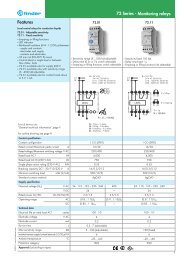
Explanation of relay marking and LED/LCD display<br />
<strong>Monitoring</strong> relay without LCD-display<br />
ON LED green steady light: supply voltage is on and measuring system is active.<br />
DEF Default: the detected value is outside of the acceptable range (asymmetric is shown by the LED ASY).<br />
LED red flashing: delay time is running, see the function diagram.<br />
LED red steady light: output relay is off, contact 11-14 (6-2) is open.<br />
ASY Phase asymmtery is outside of the predefined range.<br />
LED steady light: output relay is turned off, contact 11-14 (6-2) is open.<br />
LEVEL Selected range as % value.<br />
TIME Delay time min (minutes) or s (seconds).<br />
MEMORY ON Fault memory switched on: the state of the output relay after the accurrence of a fault –contact 11-14 (6-2) open– will be<br />
maintained, monitored value returns to within acceptable limits. Fault reset is made by switch manipulation from ON to<br />
OFF to ON, or by power down (<strong>71</strong>.31.8.400.<strong>10</strong>21 & <strong>71</strong>.92.x.xxx.0001), or by operating of the “RESET”<br />
(<strong>71</strong>.92.x.xxx.0001).<br />
MEMORY OFF Fault memory turned off: the sate of the output contatcts will only remain in the “fault” condition –contact 11-41 (6-2) open–<br />
while the monitored value is outside of the acceptable limits. When the monitored value returns within the acceptable limits<br />
the contact will revert to the energised state. Monitored equipment will start again automatically.<br />
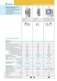
<strong>Monitoring</strong> relay with LCD-display<br />
<strong>71</strong> <strong>Series</strong> - <strong>Monitoring</strong> <strong>relays</strong> <strong>10</strong> A<br />
SET/RESET Relay <strong>71</strong>.41 and <strong>71</strong>.51. Sets and resets the programmable values - see operating in the packing.<br />
SELECT Relay <strong>71</strong>.41 and <strong>71</strong>.51. Selects the desired parameter for programming - see operating instructions.<br />
DEF Default, LED red steady or flashing.<br />
PROG Modus Enter the programming mode by simultaneously pressing the buttons “SET/RESET” and “SELECT” for 3 seconds.<br />
The word “prog” is shown for 1 second. “SELECT” allows the choise of “AC” or “DC”, and is confirmed with “SET/RESET”.<br />
Successively pressing the button “SELECT” brings up the choises of Up, or UpLo. The appropriate choise is made by pressing the “SET/RESET” button.<br />
The next step will program the appropriate values and the selection of the fault memory function (which is selected with a<br />
“YES” or “NO”). If all programming steps are completed the display will read “end”.<br />
Short programmin After repeatedly pressing the “SET/RESET” button the measured value will be displayed, or “0” appears if nothing is<br />
instruction connected to Z1 and Z2 (5 and 9). If the programming is brocken off before “end” is shown in the display the previous<br />
Program query<br />
program will remain unchanged after an interruption of the supply voltage.<br />
Pushing the “SELECT” button for at least 1 second, enters the “program inquiry mode”. The programmed mode and the<br />
values are shown on the repeated pressing of the “SELECT” button.<br />
Flashing M (memory) Fault memory has had effect (fault acknowledgement and reset is made by a 1 second press of the “SET/RESET” button).<br />
LCD-display V = volt Level= value t1 = T1 - time during which short-time<br />
A = amp Hys = hysteresis fulctuations are not taken into account<br />
Up = upper limit (with hysteresis in down direction) M = memory (fault) t2 = T2 - (monitoring relay <strong>71</strong>.51) the time<br />
Lo = lower limit (with hysteresis in up direction) Yes = yes - with memory during which inrush currents are not<br />
UpLo = upper and lower limit - range detecting no = no - without memory taken into a account<br />
9