PDF (Chapter 4 -- Internal Combustion Engines)
PDF (Chapter 4 -- Internal Combustion Engines)
PDF (Chapter 4 -- Internal Combustion Engines)

You also want an ePaper? Increase the reach of your titles
YUMPU automatically turns print PDFs into web optimized ePapers that Google loves.
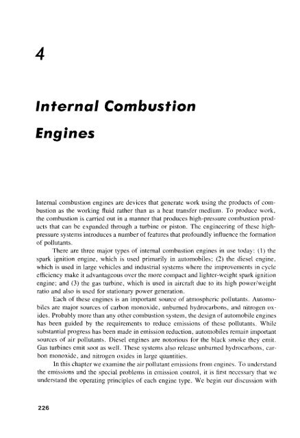
4<br />
<strong>Internal</strong> <strong>Combustion</strong><br />
<strong>Engines</strong><br />
<strong>Internal</strong> combustion engines are devices that generate work using the products of combustion<br />
as the working fluid rather than as a heat transfer medium. To produce work,<br />
the combustion is carried out in a manner that produces high-pressure combustion products<br />
that can be expanded through a turbine or piston. The engineering of these highpressure<br />
systems introduces a number of features that profoundly influence the formation<br />
of pollutants.<br />
There are three major types of internal combustion engines in use today: (1) the<br />
spark ignition engine, which is used primarily in automobiles; (2) the diesel engine,<br />
which is used in large vehicles and industrial systems where the improvements in cycle<br />
efficiency make it advantageous over the more compact and lighter-weight spark ignition<br />
engine; and (3) the gas turbine, which is used in aircraft due to its high power/weight<br />
ratio and also is used for stationary power generation.<br />
Each of these engines is an important source of atmospheric pollutants. Automobiles<br />
are major sources of carbon monoxide, unburned hydrocarbons, and nitrogen oxides.<br />
Probably more than any other combustion system, the design of automobile engines<br />
has been guided by the requirements to reduce emissions of these pollutants. While<br />
substantial progress has been made in emission reduction, automobiles remain important<br />
sources of air pollutants. Diesel engines are notorious for the black smoke they emit.<br />
Gas turbines emit soot as well. These systems also release unburned hydrocarbons, carbon<br />
monoxide, and nitrogen oxides in large quantities.<br />
In this chapter we examine the air pollutant emissions from engines. To understand<br />
the emissions and the special problems in emission control, it is first necessary that we<br />
understand the operating principles of each engine type. We begin our discussion with<br />
226
Sec. 4.1 Spark Ignition <strong>Engines</strong> 227<br />
a system that has been the subject of intense study and controversy-the spark ignition<br />
engine.<br />
4.1 SPARK IGNITION ENGINES<br />
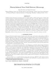
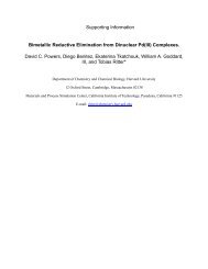
The operating cycle of a conventional spark ignition engine is illustrated in Figure 4.1.<br />
The basic principle of operation is that a piston moves up and down in a cylinder,<br />
transmitting its motion through a connecting rod to the crankshaft which drives the vehicle.<br />
The most common engine cycle involves four strokes:<br />
1. Intake. The descending piston draws a mixture of fuel and air through the open<br />
intake valve.<br />
Intake Compression Power Exhaust<br />
II<br />
jc<br />
---L B=0°<br />
(top dead<br />
center)<br />
B = crank<br />
angle<br />
Piston<br />
Piston<br />
rod<br />
Crank<br />
B = 180°<br />
(bottom dead<br />
center)<br />
Figure 4.1 Four-stroke spark ignition engine: stroke 1. intake; stroke 2. compression;<br />
stroke 3. power; stroke 4, exhaust.
Sec. 4.1 Spark Ignition <strong>Engines</strong> 229<br />
by advancing the time of ignition to a point on the compression stroke before the piston<br />
reaches the top of its motion where the cylinder volume is smallest. This is because the<br />
combustion of the mixture takes a certain amount of time, and optimum power is<br />
developed if the completion of the combustion coincides with the piston arriving at socalled<br />
top dead center. The spark is automatically advanced as engine speed increascs.<br />
Also, a pressure diaphragm senses airflow through the carburetor and advances the spark<br />
as airflow increases.<br />
Factors other than power output must be taken into account, however, in optimizing<br />
the engine operation. If the fuel-air mixture is compressed to an excessive pressure,<br />
the mixture temperature can become high enough that the preflame reactions can<br />
ignite the charge ahead of the propagating flame front. This is followed by very rapid<br />
combustion of the remaining charge and a correspondingly fast pressure increase in the<br />
cylinder. The resultant pressure wave reverberates in the cylinder, producing the noise<br />
referred to as knock (By et al., 1981). One characteristic of the fuel composition is its<br />
tendency to autoignite, expressed in terms of an octane rating.<br />
High compression ratios and ignition spark timing that optimize engine power and<br />
efficiency lead to high octane requirements. The octane requirement can be reduced by<br />
using lower compression ratios and by delaying the spark until after the point for optimum<br />
engine performance. Emission controls require additional compromises in engine<br />
design and operation, sacrificing some of the potential engine performance to reduce<br />
emissions.<br />
4.1 .1 Engine Cycle Operation<br />
The piston sweeps through a volume that is called the displacement volume, V". The<br />
minimum volume occurs when the piston is in its uppermost position. This volume is<br />
called the clearance volume, V e . The maximum volume is the sum of these two. The<br />
ratio of the maximum volume to the clearance volume is called the compression ratio,<br />
(4.1 )<br />
The efficiency of the engine is a strong function of the compression ratio. We shall see<br />
that R e also has a strong influence on the formation of pollutants. The volume in the<br />
cylinder can be expressed as a simple function of the crank angle, (), and the ratio of the<br />
length of the piston rod to that of the crank, that is,<br />
Vd ( l<br />
V = V e + - 1 + - - cos () -<br />
2 c<br />
(4.2 )<br />
where l is the piston rod length and c is the length of the crank ann as defined in Figure<br />
4.1. The minimum volume occurs at () = 0°, commonly referred to as top dead center,<br />
TOC. The maximum volume occurs at bottom dead center, BOC, () = 180 0. These<br />
positions are illustrated in Figure 4.1.<br />
Engine speeds range from several hundred revolutions per minute (rpm) for large
230 <strong>Internal</strong> <strong>Combustion</strong> <strong>Engines</strong> Chap. 4<br />
industrial engines to 10,000 rpm or more for high-perfonnanee engines. Most automobiles<br />
operate with engine speeds in the vieinity of 3000 rpm. At this speed, each stroke<br />
in the cycle takes place in 20 ms. As an automobile is driven, the equivalence ratio and<br />
intake pressure vary with the engine load. Such changes in engine operation, however,<br />
are slow by comparison with the individual strokes. In discussing engine operation, we<br />
can assume that in anyone cycle the engine operates at constant speed, load, and equivalence<br />
ratio.<br />
We begin with a discussion of the thennodynamics of the spark ignition engine<br />
cycle and develop a model that has been used extensively in optimizing engine operation<br />
to minimize emissions and to maximize performance.<br />
The spark ignition engine is one of the few combustion systems that burns premixed<br />
fuel and air. Fuel is atomized into the air as it flows through a carburetor and<br />
vaporizes before it enters the cylinder. Even though the fuel and air are premixed prior<br />
to combustion, the gas in the cylinder becomes segmented into burned and unburned<br />
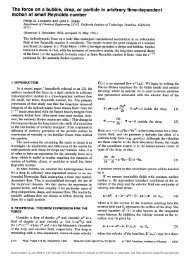
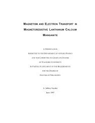
portions once ignition occurs. A flame front propagates through the cylinder as illustrated<br />
in Figure 4.3. The fuel-air mixture ahead of the flame is heated somewhat by adiabatic<br />
compression as the burning gas expands. Not only are the burned and unburned gases<br />
at widely different temperatures, but also there are large variations in the properties of<br />
the burned gases. These variations must be taken into account to predict accurately the<br />
fornlation and destruction of NO, and CO in the engine.<br />
Another important feature that distinguishes reciprocating engines from the systems<br />
discussed thus far is that the volume in which the combustion proceeds is tightly<br />
constrained. While the individual elements of fluid do expand as they burn, this expansion<br />
requires that other elements of fluid, both burned and unburned, be compressed.<br />
As a result, the burning element of fluid does work on the other fluid in the cylinder,<br />
oW = p dV, increasing its internal energy and therefore its temperature.<br />
Whilc the engine strokes are brief, the time is stilJ long by comparison with that<br />
required for pressure equilibration. For an ideal gas, the propagation rate for small pressure<br />
disturbances is the speed of sound,<br />
a, = .JyRT/M (4.3 )<br />
gas<br />
Figure 4.3 Flame propagation in the<br />
cylinder.
232 <strong>Internal</strong> <strong>Combustion</strong> <strong>Engines</strong> Chap. 4<br />
The total specific internal energy of the gas includes contributions of burned and<br />
unburned gases, with a mass fraction (X of burned gas,<br />
(4.5 )<br />
where < ) denotes an average over the entire mass of burned or unburned gas in the<br />
cylinder. The unburned gas is quite uniform in temperature (i.e.,
236<br />
Shrouded intake valve<br />
Shroud<br />
Squish<br />
<strong>Internal</strong> <strong>Combustion</strong> <strong>Engines</strong> Chap. 4<br />
Figure 4.4 Valve, head, and piston design<br />
features that enhance mixing.<br />
The dissipation rate was shown in Appendix D of <strong>Chapter</strong> 1 to be related to u I for<br />
homogeneous, isotropic turbulence,<br />
where A and I are the Taylor microscale and integral scale, respectively. Using the definition<br />
of E b we find<br />
E 3 / 2<br />
k<br />
I<br />
(4.23 )<br />
Assuming that angular momentum in the turbulent field is conserved during the rapid<br />
compression:<br />
we see that E is proportional to EL<br />
(4.24 )
238 <strong>Internal</strong> <strong>Combustion</strong> <strong>Engines</strong> Chap. 4<br />
This dependence of ftame speed on engine speed means that the number of crank<br />
angle degrees required for combustion in a given engine does not depend strongly on<br />
the engine speed. Thus, if ex ( 0) is known for one engine speed, we may use that result<br />
as an estimate of the bum rate for other engine speeds with reasonable confidence.<br />
Rather than attempt to develop detailed ftuid mechanical models of the combustion<br />
process, therefore, we shall simply specify a functional fonn for ex (0) that exhibits the<br />
essential features of actual combustion profiles, that is, a delay from the time the spark<br />
is fired until the pressure rise associated with combustion becomes appreciable, an accelerating<br />
combustion rate until a large fraction of the charge is burned, followed by a<br />
decreasing bum rate. A simple function with this sigmoidal behavior is the cosine function,<br />
(4.33)<br />
where 0 0 is the crank angle at which the spark is fired and L::. 0, is the burn duration.<br />
Other functions that allow the shape of the combustion profile to be varied have been<br />
used in the literature, but this simple function is adequate for our present purpose of<br />
exploring engine operation. We do not attempt to predict the burn duration, since it is a<br />
complex function of engine design and operation.<br />
4.1.4 Cylinder Pressure and Temperature<br />
The pressure in the cylinder can be detennined by integrating (4.19) with ex(O) given<br />
by (4.33) or another suitable model and with an expression for the heat transfer dQ / dO.<br />
The heat transfer is also a function of the turbulent field (Borgnakke et aI., 1980). For<br />
our present purposes, it is sufficient to assume that the engine is adiabatic (i.e., dQ/dO<br />
= 0).<br />
Once the pressure in the cylinder is known the mean burned and unburned gas<br />
temperatures can be calculated using (4.14) and (4.17), respectively. The temperatures<br />
of individual burned gas elements can be calculated if it is assumed that no mixing of<br />
the burned gases occurs and that heat transfer from a burned gas element is negligible.<br />
Under these assumptions, the burned gases can be assumed to undergo adiabatic<br />
compression and expansion from the time they burn. The temperature of an element<br />
burned when the mass fraction burned was ex' is<br />
(4.34 )<br />
The temperature of the element immediately following combustion, T" (ex', ex' ),<br />
may be evaluated by applying the first law of thennodynamics to the combustion of an<br />
infinitesimal mass of charge, dm. For combustion of a sufficiently small incremental<br />
mass, the pressure change during combustion is insignificant. The enthalpy of the burned<br />
gas equals that for the unburned gas, that is,<br />
- -<br />
h" = U" + R" J:, = h" = Ub + R" T"
Sec. 4.1 Spark Ignition <strong>Engines</strong> 239<br />
The burned gas temperature becomes<br />
(4.35 )<br />
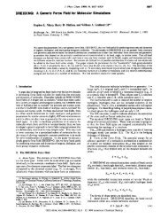
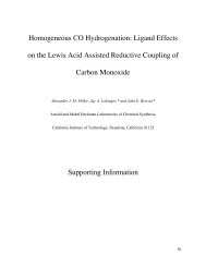
From (4.19), (4.34), and (4.35) we can detennine the pressure-temperature history<br />
of each element in the charge from the beginning to the end of combustion. Figure 4.5<br />
shows the results of calculations of Heywood (1976) for an engine with a compression<br />
ratio of 7.0. The spark is fired at 40° before top dead center. The combustion duration,<br />
t::dl" is 60°. The fraction of charge burned and the cylinder pressure are shown as a<br />
function of crank angle in Figure 4.5. The temperatures of the first and last gases to<br />
burn are shown as solid lines. The dashed curves represent the temperature of the unburned<br />
gas.<br />
The first gas to burn rises to a high temperature immediately. As additional gas<br />
burns, the pressure in the cylinder rises, compressing both burned and unburned gases.<br />
3500 1.0<br />
3000<br />
2500<br />
2000<br />
0<br />
0- x<br />
.Y.<br />
1500<br />
0- 0.4<br />
1000<br />
500<br />
3000<br />
2500<br />
Q 2000<br />
I-<br />
1500<br />
1000<br />
500<br />
245 -30 -15 0<br />
e<br />
15 30 45 60<br />
Figure 4.5 Burned mass fraction, cylinder pressure, and temperatures of the gas that<br />
bums early, Teo late, T, and the mean gas temperature inside the cylinder (after Heywood,<br />
1976).<br />
T u<br />
0.8<br />
0.6<br />
0.2<br />
0
244 <strong>Internal</strong> <strong>Combustion</strong> <strong>Engines</strong> Chap. 4<br />
The CO levels measured in fuel-lean combustion are substantially higher than those<br />
predicted with the partial-equilibrium model, but agreement is good near stoichiometric<br />
(Heywood, 1976). In fuel-rich combustion, the CO levels in the exhaust gases are close<br />
to the equilibrium concentrations, as predicted by the partial-equilibrium model. The<br />
reasons for the high levels in fuel-lean combustion are not fully understood, but may be<br />
coupled to the oxidation of unburned hydrocarbons in the exhaust manifold.<br />
4.1.7 Unburned Hydrocarbons<br />
The range of equivalence ratios over which spark ignition engines operate is narrow,<br />
typically 0.7 < cf> < 1.3, the fuel and air are premixed, and the flame temperatures are<br />
high. These conditions, in steady-flow combustion systems, generally would lead to very<br />
low emissions of unburned hydrocarbons. Why, then, are relatively large quantities of<br />
hydrocarbon gases present in the combustion products of automobile engines? This question<br />
has been the subject of numerous investigations in which hypotheses have been<br />
developed and supported with theory and experiment, only to be later challenged with<br />
new interpretations that contradict earlier models.<br />
In an early investigation of this problem, Daniel and Wentworth (1962) magnified<br />
photographs of the flame spread in the cylinder of a spark ignition engine. It was observed<br />
that the flame failed to propagate through the mixture located within 0.1 to 0.7<br />
mm of the cylinder wall. They hypothesized that this wall quenching allowed hydrocarbons<br />
to escape combustion in spark ignition engines.<br />
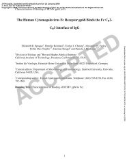
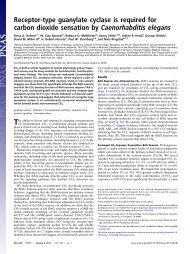
Figure 4.8 shows the nature of these wall quench regions. In addition to the quench<br />
layers at the cylinder walls, the small volume between the piston and cylinder wall above<br />
the top piston ring, called the crevice volume, contains unburned hydrocarbons. Experiments<br />
were performed in which the quench zone of an operating engine was sampled.<br />
It was found that the proportion of the quench zone exhausted is less than that of the<br />
total gas exhausted. This observation was attributed to trapping in the boundary layer.<br />
Quench layer<br />
Figure 4.8 Schematic showing the quench<br />
layer and crevice volume where heat transfer<br />
to the walls may quench the combustion<br />
(Tabaczynski et a!., 1972; © SAE, Inc.).
Sec. 4.1 Spark Ignition <strong>Engines</strong> 247<br />
(a) (b) (e)<br />
Figure 4.10 Schematic illustrating the quench layer model for hydrocarbon cmissions.<br />
(a) Quench layers are formed as heat transfer extinguishes the flame at the cool walls<br />
and in the crevice volume. (b) Gas in the crevice volume expands and is spread along<br />
the cylinder wall as the pressure falls. When the exhaust valve opens, the quench layers<br />
near the valve exit the cylinder. (c) The hydrocarbon-rich cylinder wall boundary layer<br />
rolls up into a vortex as the piston moves up the cylinder during the exhaust stroke<br />
(Tabaczynski et aI., 1972; © SAE, Inc.).<br />
by crevice gases than by the quench-layer gases (Wentworth, 1971). Adamczyk et al.<br />
(1983) examined the retention of hydrocarbons in a combustion bomb that consisted of<br />
a fixed piston in an engine cylinder. About 80% of the hydrocarbons remaining after<br />
combustion were attributed to the piston crevice, with most of the remaining hydrocarbons<br />
surviving in smaller crevices associated with the head gasket and with the threads<br />
on the spark plug. The crevice volumes contribute primarily to the peak in the hydrocarbon<br />
flux late in the exhaust process, since those gases originate far from the exhaust<br />
valve.<br />
Other sources must therefore contribute significantly to the hydrocarbon emissions,<br />
particularly those that exit the cylinder early in the exhaust process. Haskell and Legate<br />
(1972) and Wentworth (1968) suggested that lubicating oil layers on the cylinder walls<br />
may adsorb or dissolve hydrocarbon vapors during the compression stroke. These stored<br />
hydrocarbons are protected from the flame. As the pressure in the cylinder drops during<br />
the expansion stroke and exhaust process, these hydrocarbons desorb into the combustion<br />
products. Kaiser et al. (1982) showed that fuel vapors and fuel hydrocarbon oxidation<br />
product emissions increase as the amount of oil in the cylinder increases. Carrier<br />
et al. (1981) developed a model for cyclic hydrocarbon adsorption and desorption in a<br />
liquid film, taking into account thermodynamic equilibrium at the gas-liquid interface<br />
and diffusional resistance within the liquid layer. The results from this model are qualitatively<br />
consistent with the observed reduction of hydrocarbon emission with engine<br />
speed.
254 <strong>Internal</strong> <strong>Combustion</strong> <strong>Engines</strong> Chap. 4<br />
States. Ultimately, exhaust gas treatment was required to achieve acceptable emissions<br />
and performance simultaneously. Exhaust gas treatment is discussed in a subsequent<br />
section.<br />
4.1.9 Mixture Preparation<br />
The spark ignition engine bums premixed fuel and air. In conventional engines, this<br />
mixture is prepared in the carburetor, a complex device that controls both fuel and air<br />
flows to the engine. The mixture requirements depend on engine speed and load. A richer<br />
mixture is required at high load (such as during vehicle acceleration) than at low load.<br />
Even though combustion will be incomplete, fuel-rich mixtures have been used to increase<br />
the heat release per cycle, thereby increasing the power delivered by the engine.<br />
Carburetors have evolved as mechanically activated control systems that meet these requirements.<br />
As we have seen in the preceding discussion, emission controls place additional<br />
constraints on engine operation that are not readily met with purely mechanical<br />
control. To understand the need for and the nature of the new systems for mixture preparation<br />
that are being developed as part of integrated emission control systems, it is<br />
useful to examine the operation of a conventional carburetor.<br />
The power output and speed of a spark ignition engine are regulated by a throttle<br />
that limits the airflow into the engine. In conventional engines, the airflow rate is used<br />
to control the fuel/air ratio. Part of the difficulty encountered in early attempts to reduce<br />
automobile emissions derived from the complex coupling of fuel and airflow rates.<br />
A simple carburetor is illustrated in Figure 4.17. The throttle is a butterfly valve,<br />
a disk that is rotated to obstruct the airflow, producing a vacuum in the intake manifold.<br />
The low pressure reduces the mass entering the cylinders, even though the intake gas<br />
volume is fixed. The rate at which fuel is atomized into the airflow is controlled by the<br />
pressure drop in a venturi, /:!p, that is,<br />
G f = CIF .J2Pf /:!Pf (4.41 )<br />
where G/ is the fuel mass flux, C IF the flow coefficient associated with the fuel metering<br />
orifice, Pf the density, and /:!p/ the pressure drop across the fuel metering orifice. This<br />
pressure drop corresponds to the difference between the pressure drop created by the<br />
airflow through the venturi /:!Pa and the pressure needed to overcome surface tension at<br />
the nozzle exit, /:!Pu = 2a/ d, where a is the surface tension and d is the nozzle diameter.<br />
The total pressure drop becomes<br />
a<br />
/:!p/ "'" Po + p/gh - PI' - 2 d<br />
(4.42 )<br />
where PI' is the gas pressure in the venturi. The airflows in the intake system involve<br />
large pressure drops, so the compressibility of the gas must be taken into account. The<br />
pressure drop associated with the gas flow drives the fuel flow, so we need to know the<br />
relationship between pressure drop and flow rate. By considering the conservation of<br />
energy, we can readily derive such an expression for the adiabatic and thennodynamically<br />
reversible (i.e., isentropic) flow of an ideal gas.
258 <strong>Internal</strong> <strong>Combustion</strong> <strong>Engines</strong><br />
1.6<br />
o 0.2 0.4 0.6 0.8 1.0 1.2<br />
Figure 4.18 Variation of equivalence ratio with airflow rate for a simple carburetor<br />
(Taylor. 1966). Reprinted by pem1ission of MIT Press.<br />
Chap. 4<br />
opens beyond some point is a compromise solution. When the power jet is fully open,<br />
the fuel flow is about 10% more than that supplied by the main jet.<br />
If the throttle is rapidly opened (as when the gas pedal of a car is quickly depressed),<br />
the fuel flow does not respond instantly. To improve the engine response, an<br />
accelerator pump may be used to supply fuel at a rate that is proportional to the speed<br />
of the accelerator motion.<br />
A very fuel-rich mixture is used to start a cold engine, on the assumption that if<br />
enough fuel is introduced into the intake manifold, some of it will surely evaporate and<br />
start the engine. A butterfly valve called a choke is installed between the impact tube<br />
and the venturi, as illustrated in Figure 4.19, to increase the pressure drop and therefore<br />
the fuel flow rate through the main metering orifice. The choke is frequently operated<br />
automatically, controlled by the exhaust manifold temperature and the inlet manifold<br />
pressure. Rich operation during startup leads to high CO and hydrocarbon emissions.<br />
As much as 40% of the hydrocarbons emitted during automotive test cycles may be<br />
released during the warm-up phase.<br />
We have examined only a few of the features that have been incorporated into<br />
automotive carburetors. Since the carburetor directly controls the equivalence ratio of<br />
the mixture reaching the engine, it plays a central role in the control of automotive<br />
emissions. Much more elaborate fuel metering systems have been developed to achieve
Sec. 4.1<br />
Cam<br />
Power-jet<br />
metering<br />
orifice<br />
Spark Ignition <strong>Engines</strong><br />
Air<br />
259<br />
Figure 4.19 Carburetor with power jet and<br />
choke (Taylor, 1966). Reprinted by pennission<br />
of MIT Press.<br />
the fine regulation required for emission control. Electronically manipulated valves have<br />
replaced the simple mechanically controlled fuel metering, facilitating more precise control<br />
of engine operation through the use of computers.<br />
Fuel injection is used in place of carburetion in some spark ignition engines because<br />
the quantity of fuel introduced can be controlled independently of the airflow rate.<br />
Atomization of high-pressure fuel replaces the flow-induced fuel intake of conventional<br />
carburetors. Fuel may be injected into the intake manifold (injection carburetion) so that<br />
the mixture is controlled by an injector pump rather than being directly coupled to the<br />
airflow. Injection into the inlet ports allows cylinder-by-cylinder regulation of the equivalence<br />
ratio. Direct injection into the cylinder is also used in some engines, although<br />
this method is more sensitive to spray characteristics and may lead to imperfect mixing<br />
of fuel and air. Injection systems are becoming more common because they are so well<br />
suited to integration into feedback-controlled engine operation.<br />
4.1.10 Intake and Exhaust Processes<br />
The flows through the intake and exhaust valves also influence engine operation and<br />
emissions. We have seen that the intake flow induces turbulence that, after amplification<br />
by rapid compression, governs the flame propagation. The opening of the exhaust valve<br />
near the end of the expansion stroke causes a sudden pressure decrease and adiabatic<br />
cooling that influence carbon monoxide emissions.
Sec. 4.1 Spark Ignition <strong>Engines</strong> 261<br />
sition, engine speed, and engine temperature can be expected to be important factors in<br />
the fonnation of pollutants.<br />
4.1 .11 Crankcase Emissions<br />
Crankcase emissions are caused by the escape of gases from the cylinder during the<br />
compression and power strokes. The gases escape between the sealing surfaces of the<br />
piston and cylinder wall into the crankcase. This leakage around the piston rings is<br />
commonly called blowby. Emissions increase with increasing engine airflow, that is,<br />
under heavy load conditions. The resulting gases emitted from the crankcase consist of<br />
a mixture of approximately 85% unburned fuel-air charge and 15% exhaust products.<br />
Because these gases are primarily the carbureted fuel-air mixture, hydrocarbons are the<br />
main pollutants. Hydrocarbon concentrations in blowby gases range from 6000 to 15,000<br />
ppm. Blowby emissions increase with engine wear as the seal between the piston and<br />
cylinder wall becomes less effective. On cars without emission controls, blowby gases<br />
are vented to the atmosphere by a draft tube and account for about 25 % of the hydrocarbon<br />
emissions.<br />
Blowby was the first source of automotive emissions to be controlled. Beginning<br />
with 1963 model cars, this category of vehicular emissions has been controlled in cars<br />
made in the United States. The control is accomplished by recycling the blowby gas<br />
from the crankcase into the engine air intake to be burned in the cylinders, thereby<br />
keeping the blowby gases from escaping into the atmosphere. All control systems use<br />
essentially the same approach, which involves recycling the blowby gases from the engine<br />
oil sump to the air intake system. A typical system is shown in Figure 4.21. Ventilation<br />
air is drawn down into the crankcase and then up through a ventilator valve and<br />
hose and into the intake manifold. When airflow through the carburetor is high, additional<br />
air from the crankcase ventilation system has little effect on engine operation.<br />
However, during idling, airflow through the carburetor is so low that the returned blowby<br />
gases could alter the air-fuel ratio and cause rough idling. For this reason, the flow<br />
control valve restricts the ventilation flow at high intake manifold vacuum (low engine<br />
speed) and permits free flow at low manifold vacuum (high engine speed). Thus high<br />
ventilation rates occur in conjunction with the large volume of blowby associated with<br />
high speeds; low ventilation rates occur with low-speed operation. Generally, this principle<br />
of controlling blowby emissions is called positive crankcase ventilation (PCV).<br />
4.1.12 Evaporative Emissions<br />
Evaporative emissions issue from the fuel tank and the carburetor. Fuel tank losses result<br />
from the evaporation of fuel and the displacement of vapors when fuel is added to the<br />
tank. The amount of evaporation depends on the composition of the fuel and its temperature.<br />
Obviously, evaporative losses will be high if the fuel tank is exposed to high<br />
ambient temperatures for a prolonged period of time. The quantity of vapor expelled<br />
when fuel is added to the tank is equal to the volume of the fuel added.<br />
Evaporation of fuel from the carburetor occurs primarily during the period just
262 <strong>Internal</strong> <strong>Combustion</strong> <strong>Engines</strong> Chap. 4<br />
Crankcase<br />
ventilator<br />
valve<br />
Figure 4.21 Crankcase emission control system.<br />
Oil filler cap<br />
after the engine is turned off. During operation the carburetor and the fuel in the carburetor<br />
remain at about the temperature of the air under the hood. But the airflow ceases<br />
when the engine is stopped, and the carburetor bowl absorbs heat from the hot engine,<br />
causing fuel temperatures to reach 293 to 313 K above ambient and causing gasoline to<br />
vaporize. This condition is called a hot soak. The amount and composition of the vapors<br />
depend on the fuel volatility, volume of the bowl, and temperature of the engine prior<br />
to shutdown. On the order of 10 g of hydrocarbons may be vaporized during a hot soak.<br />
Fuel evaporation from both the fuel tank and the carburetor accounts for approximately<br />
20% of the hydrocarbon emissions from an uncontrolled automobile.<br />
It is clear that gasoline volatility is a primary factor in evaporative losses. The<br />
measure of fuel volatility is the empirically detennined Reid vapor pressure, which is a<br />
composite value reflecting the cumulative effect of the individual vapor pressures of the<br />
different gasoline constituents. It provides both a measure of how readily a fuel can be<br />
vaporized to provide a combustible mixture at low temperatures and an indicator of the<br />
tendency of the fuel to vaporize. In a complex mixture of hydrocarbons, such as gasoline,<br />
the lowest-molecular-weight molecules have the greatest tendency to vaporize and<br />
thus contribute more to the overall vapor pressure than do the higher-molecular-weight<br />
constituents. As the fuel is depleted of low-molecular-weight constituents by evaporation,<br />
the fuel vapor pressure decreases. The measured vapor pressure of gasoline therefore<br />
depends on the extent of vaporization during the test. The Reid vapor-pressure<br />
detennination is a standard test at 311 K in which the final ratio of vapor volume to
Sec. 4.1 Spark Ignition <strong>Engines</strong> 265<br />
air to be drawn through the canister, carrying the trapped hydrocarbons to the intake<br />
manifold to be burned.<br />
4.1 .13 Exhaust Gas Treatment<br />
Modification of engine operation yields only modest emission reductions, and the penalties<br />
in engine performance and efficiency are substantial. An alternative way to control<br />
emissions involves the treatment of the exhaust gas in chemical reactors. Carbon monoxide,<br />
unburned hydrocarbons, and nitrogen oxides are all present in the exhaust gases<br />
in concentrations that are far in excess of the equilibrium values. If all the pollutants are<br />
to be controlled by exhaust gas treatment, it is necessary to oxidize carbon monoxide<br />
and hydrocarbons while reducing nitrogen oxides. Exhaust gas treatment may utilize<br />
either catalytic converters or noncatalytic thermal reactors.<br />
Thermal reactors. The gas-phase oxidation of carbon monoxide slows dramatically<br />
as combustion products cool, but the reaction does not stop entirely. In fact, carbon<br />
monoxide and hydrocarbons continue to react in the exhaust manifold. To oxidize<br />
the hydrocarbons homogeneously requires a holding time of order 50 ms at temperatures<br />
in excess of 900 K. Homogeneous oxidation of carbon monoxide requires higher temperatures,<br />
in excess of 1000 K. The oxidation rate can be enhanced with a thermal<br />
reactor-an enlarged exhaust manifold that bolts directly onto the cylinder head. The<br />
thermal reactor increases the residence time of the combustion products at temperatures<br />
sufficiently high that oxidation reactions can proceed at an appreciable rate. To allow<br />
for fuel-rich operation, secondary air may be added and mixed rapidly with combustion<br />
products.<br />
A multiple-pass arrangement is commonly used in thermal reactors to shield the<br />
hot core of the reactor from the relatively cold surroundings. This is critical since the<br />
reactions require nearly adiabatic operation to achieve significant conversion, as illustrated<br />
in Figure 4.24. Typically, only about a factor of 2 reduction in emission levels<br />
for CO and hydrocarbons can be achieved even with adiabatic operation. Higher temperatures<br />
and long residence times are typically required to achieve better conversions.<br />
The heat released in the oxidation reactions can result in a substantial temperature rise<br />
and, thereby, promote increased conversion. Removal of 1.5 % CO results in a temperature<br />
rise of about 490 K (Heywood, 1976). Hence thermal reactors with fuel-rich cylinder<br />
exhaust gas and secondary air addition give greater fractional reductions in CO<br />
and hydrocarbon levels than reactors with fuel-lean cylinder exhaust. Incomplete combustion<br />
in the cylinder, however, does result in reduced fuel economy. The attainable<br />
conversion is limited by incomplete mixing of gases exhausted at various times in the<br />
cycle and any secondary air that is added.<br />
Temperatures of the exhaust gases of automobile spark ignition engines can vary<br />
from 600 to 700 K at idle to 1200 K during high-power operation. Most of the time the<br />
exhaust temperature is between 700 and 900 K, too low for effective homogeneous oxidation.<br />
Spark retard increases the exhaust temperature, but this is accompanied by a<br />
significant loss in efficiency.
Sec. 4.2 Diesel Engine 269<br />
the replacement of mechanically coupled carburetors with systems better suited to elec<br />
tronic control.<br />
Feedback control of engines using exhaust gas sensors results in operation that<br />
oscillates about the stoichiometric condition in a somewhat periodic manner (Kummer,<br />
1980). The frequency of these oscillations is typically on the order of 0.5 to 4 Hz, with<br />
excursions in equivalence ratio on the order of ±O.Ol equivalence ratio units.<br />
In addition to NO, CO, and unoxidized hydrocarbons, catalyst-equipped spark<br />
ignition engines can emit sulfuric acid aerosol, aldehydes, and under rich conditions,<br />
H 2 S. Unleaded gasoline typically contains 15G to 600 ppm by weight of sulfur. The<br />
sulfur leaves the cylinder as S02, but the catalyst can promote further oxidation to SO,.<br />
As the combustion products cool, the SO, combines with water to form an H 2S04 aerosol.<br />
H 2 S formation requires high catalyst temperatures (> 875 K) and a reducing atmosphere.<br />
This may occur, for example, when an engine is operated steadily at high speed<br />
for some time under fuel-lean conditions and is then quickly slowed to idle fuel-rich<br />
operation. HCN formation may occur under similar conditions.<br />
During startup, when the catalyst is cold, hydrocarbons may be only partially oxidized,<br />
leading to the emission of oxygenated hydrocarbons. Aldehyde emissions, however,<br />
are generally low when the catalyst is hot.<br />
4.2 DIESEL ENGINE<br />
Like the spark ignition engine, the diesel is a reciprocating engine. There is, however,<br />
no carburetor on the diesel. Only air (and possibly recycled combustion products for<br />
NO, control by EGR) is drawn into the cylinder through the intake valve. Fuel is injected<br />
directly into the cylinder of the diesel engine, beginning toward the end of the compression<br />
stroke. As the compression heated air mixes with the fuel spray, the fuel evaporates<br />
and ignites. Relatively high pressures are required to achieve reliable ignition. Excessive<br />
peak pressures are avoided by injecting the fuel gradually, continuing far into the expansion<br />
stroke.<br />
The rate at which the fuel is injected and mixes with the air in the cylinder determines<br />
the rate of combustion. This injection eliminates the need to throttle the airflow<br />
into the engine and contributes to the high fuel efficiency of the diesel engine. As in the<br />
steady-flow combustor, turbulent mixing profoundly influences the combustion process<br />
and pollutant formation. The unsteady nature of combustion in the diesel engine significantly<br />
complicates the process. Rather than attempt to develop quantitative models of<br />
diesel emissions, we shall explore some of the features that govern the formation of<br />
pollutants in diesel engines.<br />
Several diesel engine configurations are in use today. Fuel is injected directly into<br />
the cylinder of the direct injection (DI) diesel, illustrated in Figure 4.27(a). In the direct<br />
injection diesel engine, most of the turbulence is generated prior to combustion by the<br />
airflow through the intake valve and the displacement of gases during the compression<br />
stroke. The fuel jet is turbulent, but the time scale for mixing is comparable to that for<br />
entrainment, so the gas composition does not approach homogeneity within the fuel jet.
Sec. 4.2 Diesel Engine 271<br />
ever. The flow through the orifice connecting the prechamber to the cylinder results in<br />
a pressure drop, thereby reducing the efficiency of the engine.<br />
Diesel engines may also be classified into naturally aspirated (NA), supercharged,<br />
or turbocharged types, depending on the way the air is introduced into the cylinder. In<br />
the naturally aspirated engine, the air is drawn into the cylinder by the piston motion<br />
alone. The supercharger is a mechanically driven compressor that increases the airflow<br />
into the cylinder. The turbocharger similarly enhances the intake airflow by passing the<br />
hot combustion products through a turbine to drive a centrifugal (turbine-type) compressor.<br />
Compression of the air prior to introduction into the cylinder results in compression<br />
heating. This may be detrimental from the point of view of NO, formation because it<br />
increases the peak combustion temperature. An intercooler may be installed between the<br />
compressor and the intake valve to reduce this heating.<br />
The fuel is sprayed into the cylinder through a number of small nozzles at very<br />
high pressure. The liquid stream issuing from the injector nozzle moves with high velocity<br />
relative to the gas. The liquid stream fonns filaments that break into large droplets.<br />
The breakup of the droplets in the fuel spray is characterized by the Weber number, the<br />
ratio of the inertial body forces to surface tension forces,<br />
We<br />
where P g is the gas density, v the relative velocity between the gas and the droplets, and<br />
a the surface tension of the liquid. As long as the Weber number exceeds a critical value<br />
of approximately 10, the droplets will continue to break into smaller droplets. Aerodynamic<br />
drag on the droplets rapidly decelerates them and accelerates the gas entrained<br />
into the fuel spray. Evaporation and combustion of the fuel can be described using the<br />
model developed in Section 2.7. In some cases, however, pressures and temperatures in<br />
the cylinder are high enough that the liquid fuel is raised above its critical point. The<br />
fuel spray then behaves like a dense gas jet.<br />
The entrainment of air into the unsteady, two-phase, variable-density, turbulent<br />
jet has been described by a variety of empirical models, simple jet entrainment models,<br />
and detailed numerical simulations. The problem is frequently complicated further by<br />
the use of swirling air motions to enhance mixing and entrainment. The swirling air<br />
motion sweeps the fuel jet around the cylinder, spreading it and reducing impingement<br />
on the cylinder wall. Since combustion in nonpremixed systems generally occurs predominantly<br />
at equivalence ratios near unity, combustion will occur primarily on the<br />
perimeter of the jet. Mixing of hot combustion products with the fuel-rich gases in the<br />
core of the fuel spray provides the environment in which large quantities of soot can be<br />
readily generated. (We discuss soot fonnation in <strong>Chapter</strong> 6.) The stoichiometric combustion<br />
results in high temperatures that promote rapid NOt fonnation in spite of operation<br />
with large amounts of excess air in the cylinder under most operating conditions.<br />
Some of the fuel mixes with air to very low equivalence ratios before any of the mixture<br />
ignites. Temperatures in this region may be high enough for some fuel decomposition<br />
a
272 <strong>Internal</strong> <strong>Combustion</strong> <strong>Engines</strong> Chap. 4<br />
and partial oxidation to occur, accounting for the relative abundance of aldehydes and<br />
other oxygenates in the dicsel emissions (Henein, 1976).<br />
Thus we see that diesel engines exhibit all of the complications of steady-flow<br />
spray flames, in addition to being unsteady. To describe the formation of pollutants<br />
quantitatively would require the development of a probability density function description<br />
of the unsteady mixing process. While such models are being explored (Mansouri<br />
et a!., 1982a,b; Kort et a!., 1982; Siegla and Amann, 1984), the methods employed are<br />
beyond the scope of this book. We shall examine, instead, the general trends as seen in<br />
both experimental and theoretical studies of diesel engine emissions and emission<br />
control.<br />
4.2.1 Diesel Engine Emissions and Emission Control<br />
Relatively low levels of gaseous exhaust emissions are achieved by light-duty (automobile)<br />
diesel engines without the use of exhaust gas treatment usually applied to gasoline<br />
engines to achieve similar emission levels (Wade, 1982).<br />
The species mole fractions in diesel exhaust are somewhat misleading because of<br />
the low and variable equivalence ratios at which diesel engines typically operate. At<br />
low-load conditions, the operating equivalence ratio may be as low as 0.2, so the pollutants<br />
are diluted significantly with excess air. Because the equivalence ratio is continually<br />
varying in normal use of diesel engines, and to facilitate comparison to other engines,<br />
it is more appropriate to report emission levels in terms of emissions per unit of<br />
output: g Mr 1 for stationary engines or heavy-duty vehicles or g km- 1 for light-duty<br />
vehicular diesel engines.<br />
Injection of the liquid fuel directly into the combustion chamber of the diesel engine<br />
avoids the crevice and wall quench that allows hydrocarbons to escape oxidation<br />
in carbureted engines, so hydrocarbon emissions from diesel engines are relatively low.<br />
Furthermore, diesel engines typically operate fuel-lean, so there is abundant oxygen to<br />
burn some of the hydrocarbons and carbon monoxide formed in midair in the cylinder.<br />
NO, emissions from prechamber diesel engines are lower than the uncontrolled NO,<br />
emissions from homogeneous charge gasoline engines (Wade, 1982). The low NO,<br />
emissions result from the staged combustion in the prechamber diesel and the inhomogeneous<br />
gas composition. Particulate emissions from diesel engines tend to be considerably<br />
higher than those of gasoline engines and represent a major emission control<br />
challenge.<br />
Factors that influence the emissions from diesel engines include the timing and<br />
rate of fuel injection, equivalence ratio, compression ratio, engine speed, piston and<br />
cylinder design, including the use of prechambers, and other design factors. The influence<br />
of the overall equivalence ratio on engine performance is shown in Figure 4.28(a).<br />
The brake mean effective pressure increases with equivalence ratio, so higher equivalence<br />
ratios correspond to higher engine power output or load. The exhaust gas temperature<br />
also increases with equivalence ratio. Fuel consumption is high at low equivalence<br />
ratio, but decreases sharply as the equivalence ratio is increased. As the equivalence
274 <strong>Internal</strong> <strong>Combustion</strong> <strong>Engines</strong> Chap. 4<br />
ratio approaches unity, the fuel consumption increases slightly above a minimum value<br />
at about ¢ = 0.5.<br />
The variation of emissions with equivalence ratio is shown in Figure 4.28(b). In<br />
terms of grams emitted per MJ of engine output, all of the emissions are high at low<br />
equivalence ratios for which the engine output is small. Carbon monoxide and particulate<br />
emissions drop sharply with increasing equivalence ratio, pass through a minimum at<br />
about ¢ = 0.5, and then rise sharply as ¢ approaches unity. Hydrocarbon and nitrogen<br />
oxide emissions, on the other hand, drop sharply as ¢ is increased above about 0.2,<br />
reaching relatively low levels at an equivalence ratio of about 0.4, and changing only<br />
slightly thereafter. It should be noted that, while the brake specific emissions of the latter<br />
pollutants decrease with increasing load, the absolute emission rate may increase at high<br />
power output.<br />
While CO and hydrocarbon levels in diesel exhausts are quite low, particulate<br />
emissions from diesel engines are considerably higher than those from comparable spark<br />
ignition engines. The high particulate emissions are a consequence of the direct injection<br />
of fuel into the cylinder or prechamber of the diesel engine. The mixing is relatively<br />
slow, allowing some of the fuel to remain in hot, fuel rich gases long enough for polymerization<br />
reactions to produce the high-molecular-weight hydrocarbons that ultimately<br />
form carbonaceous particles known as soot. Subsequent mixing is slow enough that<br />
many of the particles escape oxidation in spite of the large amount of excess air that is<br />
typically available in the diesel engine. NO, levels are also high because combustion in<br />
the turbulent diffusion flame of the diesel engine takes place in regions that are near<br />
stoichiometric. Because the diesel engine generally operates very fuel lean, reduction<br />
catalysts are not a practical solution to the NO x emission problem. The exhaust temperature<br />
varies considerably with load and is on the low side for noncatalytic reduction by<br />
ammonia. Thus, until a feasible system for removing NO x from diesel exhausts is developed,<br />
diesel NO, control strategies must be based on modification of the combustion<br />
process. As with the spark ignition engine, penalties in fuel economy or engine performance<br />
may result. Moreover, efforts to improve the fuel economy or performance may<br />
aggravate the emission problem.<br />
Diesel NO x emissions result from the thermal fixation of atmospheric nitrogen, so<br />
control of these emissions can be achieved by reducing the peak flame temperatures.<br />
Equivalence ratio has, as we saw in Figure 4.28, relatively little influence on NOt emissions<br />
from the diesel engine. The diffusion flame allows much of the combustion to take<br />
place at locally stoichiometric conditions regardless of the overall equivalence ratio. The<br />
peak temperatures can be reduced, however, through exhaust gas recirculation or retarding<br />
the injection timing. Exhaust gas recirculation in the diesel engine serves the<br />
same purpose as in the spark ignition engine: that of reducing the peak flame temperature<br />
through dilution with combustion products. Like spark retard, injection timing delays<br />
cause the heat release to occur late in the cycle, after some expansion work has occurred,<br />
thereby lowering the peak temperatures. The influence of these two control strategies on<br />
emissions and performance of an indirect injection automotive diesel engine is shown in<br />
Figure 4.29. Below about 30 percent exhaust gas recirculation, hydrocarbon, carbon<br />
monoxide, and particulate emissions are not significantly influenced by exhaust gas re-
Sec. 4.3 Stratified Charge <strong>Engines</strong> 277<br />
Due to the relatively low nitrogen content of light diesel fuels, the fornlation of<br />
nitric oxide in the diesel engine is primarily by the thermal fixation of atmospheric ni-<br />
trogen. Diesel engines can be operated, however, on heavier liquid fuels, or even on<br />
coal. The possible contributions of fuel-nitrogen to NO, emissions must be considered<br />
for such operations.<br />
4.2.2 Exhaust Gas Treatment<br />
The diesel engine typically operates fuel-lean. The presence of excess oxygen in the<br />
combustion products suggests that the oxidation of carbon monoxide, hydrocarbon vapors,<br />
and carbonaceous particles in the exhaust gases may be possible. Wade (1980)<br />
examined the possibility of oxidizing the particles in the exhaust gases using a long<br />
exhaust reactor. At temperatures below 1000 K, the mass lost in 10 s due to oxidation<br />
was insignificant. At 1100 K, some mass was consumed by oxidation, but 3 s was required<br />
for an 80% reduction in the exhaust mass loading. Temperatures on the order of<br />
1370 K would probably be required to achieve significant oxidation in a thermal reactor<br />
with a volume the same as the engine displacement. Thus oxidation of the particulate<br />
matter as it flows through an exhaust system does not appear to be a practical solution<br />
to the particulate emissions from vehicular diesel engines. The large temperature swings<br />
of the diesel exhaust temperature-in particular, the low temperatures encountered during<br />
low-load operation-make the .thermal reactor impractical even for CO and hydrocarbon<br />
vapor emission control unless some additional fuel is added to raise the temperature.<br />
An oxidation catalyst might be useful for the oxidation of carbon monoxide and<br />
hydrocarbons, particularly if it were effective in removing the condensible organics that<br />
contribute to the particulate emissions and the partially oxygenated hydrocarbons that<br />
are responsible for the diesel exhaust odor. The particulate matter deposition on the<br />
catalyst may affect the performance.<br />
Filters or electrostatic precipitators can be used to remove particles from the exhaust<br />
gas stream, but disposal becomes a logistical problem in vehicular applications.<br />
These devices can be used, however, to concentrate the particulate matter for subsequent<br />
on-board incineration (Sawyer et aI., 1982). After a sufficient quantity of particulate<br />
matter has been collected to sustain combustion, the collected carbonaceous material can<br />
be ignited by an auxiliary heat source and burned. This cleans the particle trap and allows<br />
extended operation without the buildup of such heavy deposits that engine back-pressure<br />
becomes a problem. A filter element may be impregnated with a catalyst to promote<br />
oxidation of the collected material at lower temperatures. Maintaining the trap at low<br />
temperature during the collection phase would facilitate the collection of vapors that<br />
would otherwise condense or adsorb on the soot particles upon release into the atmosphere.<br />
Periodic regeneration could be performed automatically using microprocessor<br />
control and sensors to monitor the status of the trap during the collection and regeneration<br />
phases of operation.<br />
Filter elements may take the form of wire meshes, ceramic monoliths, or ceramic<br />
foams. Due to the wide range of temperatures and rapid changes to which the trap is<br />
exposed, the durability of these elements is a critical issue in the development of this
278 <strong>Internal</strong> <strong>Combustion</strong> <strong>Engines</strong> Chap. 4<br />
technology. If thennal shock leads to the development of cracks or fissures through<br />
which the exhaust can flow, the collection efficiency may be seriously degraded.<br />
Reduction of NO, in diesel exhaust gases represents a fonnidable challenge. Threeway<br />
catalysts are not effective because of the large amount of excess oxygen. The exhaust<br />
temperature varies over too wide a range for the noncatalytic ammonia injection<br />
technique to be useful, and the soot particles in the diesel exhaust are likely to foul or<br />
poison catalysts in the catalytic ammonia injection unless very effective particle removal<br />
is achieved. Alternative reducing agents that work at lower temperature, such as isocyanic<br />
acid (Perry and Siebers, 1986), may ultimately prove effective in diesel engine<br />
NO, emission control.<br />
4.3 STRATIFIED CHARGE ENGINES<br />
The emphasis in our discussion of spark ignition engines has been on the homogeneous<br />
charge engines. The range of equivalence ratios over which such engines can operate<br />
has been seen to be very narrow due to the low laminar flame speed in rich or lean<br />
mixtures. The diesel engine, on the other hand, can operate at very low equivalence<br />
ratios. Soot fonnation in the compression ignition engine remains a serious drawback to<br />
its use.<br />
An alternative approach that is internlediate between these two types of reciprocating<br />
engines is a stratified charge engine. Stratified charge engines rely on a spark for<br />
ignition as in the homogeneous charge engine, but utilize a nonunifonn fuel distribution<br />
to facilitate operation at low equivalence ratios. The concept of the stratified charge<br />
engine is not new. Since the 1930s attempts have been made to develop hybrid engines<br />
that incorporate the best features of both the spark ignition and diesel engines (Heywood,<br />
1981). Some, like the diesel, involve direct injection of the fuel into the cylinder. In<br />
others, two carbureted fuel-air mixtures are introduced into the cylinder, a rich mixture<br />
into a small prechamber and a lean mixture into the main cylinder.<br />
Figure 4.30 illustrates the latter type of engine. The idea behind the prechamber<br />
stratified charge engine is that the fuel-rich mixture is easier to ignite than is the lean<br />
Figure 4.30 Prechamber stratified charge<br />
engine.
Sec. 4.3 Stratified Charge <strong>Engines</strong> 279<br />
mixture in the main cylinder. The spark ignites the mixture in the prechamber. As it<br />
burns, the rich mixture expands, fonning a jet through the orifice connecting the two<br />
chambers. The high-velocity flow of hot combustion products rapidly mixes with and<br />
ignites the lean mixture in the main cylinder. By this route, only a small fraction of the<br />
combustion takes place near stoichiometric, with most occurring well into the fuel-lean<br />
region. Thus NO, fonnation is substantially slower than in a homogeneous charge engine.<br />
The simplest conceptual model for the prechamber stratified charge engine is to<br />
assume that the mixture in the prechamber is unifonn at a high equivalence ratio and<br />
that the mixture in the main cylinder is unifonn at a lower value of 1>. This assumption,<br />
however, is rather tenuous. During the intake stroke, the two mixtures flow through the<br />
two intake valves. Because of the large displacement volume, some of the prechamber<br />
mixture may flow out through the connecting orifice into the main chamber during intake.<br />
In the compression stroke, gas from the main chamber is forced back into the<br />
prechamber, so the prechamber will contain a mix of the rich and lean charges. Some<br />
of the prechamber mixture will remain in the main chamber. Thus, in spite of using<br />
carburetors to prepare the two charges, the two mixtures may not be unifonn at ignition.<br />
During combustion, further mixing between the two gases takes place.<br />
Analysis of gas samples collected at the exhaust port suggests that no significant<br />
stratification of the mixture remains at the end of the expansion stroke. This does not<br />
mean, however, that the gas is unifonnly mixed on the microscale. As in the diesel<br />
engine, the turbulent mixing process plays a critical role in detennining the pollutant<br />
emission levels. The dependence of the emissions from the prechamber stratified charge<br />
engine on equivalence ratio, as a result, is somewhat weaker than that of the conventional<br />
homogeneous charge engine. The reduction in the peak NO, emissions with this<br />
technology is modest, but the ability to operate at very low equivalence ratios makes<br />
significant emission reductions possible.<br />
Other types of stratified-charge engines utilize direct injection of the fuel into the<br />
cylinder to create local variations in composition. The fuels used in such engines generally<br />
still have the high-volatility characteristics of gasoline, and a spark is used for<br />
ignition. Two types of direct-injection stratified-charge engines are shown in Figure<br />
4.31. The early injection version of the direct-injection stratified-charge engine typically<br />
uses a broad conical spray to distribute the fuel in the central region of the cylinder,<br />
where the piston has a cup. The spray starts early, about halfway through the compression<br />
stroke, to give the large fuel droplets produced by the low-pressure injector time to<br />
evaporate prior to ignition. In contrast, a late injection engine more closely resembles a<br />
diesel engine. A high-pressure injector introduces a narrow stream of fuel, beginning<br />
just before combustion. A swirling air motion carries the spray toward the spark plug.<br />
The details of combustion in these engines are not well understood. Mixing and<br />
combustion occur simultaneously, so the dependence of emissions on equivalence ratio<br />
more closely resembles the weak dependence of poorly mixed steady-flow combustors<br />
than that of the conventional gasoline engine. Because pure fuel is present in the cylinder<br />
during combustion, the direct-injection stratified-charge engines suffer from one of the<br />
major difficulties of the diesel engine: soot is fonned in significant quantities.<br />
These are but a few of the possible configurations of reciprocating engines. The
280 <strong>Internal</strong> <strong>Combustion</strong> <strong>Engines</strong><br />
(a)<br />
(b)<br />
Figure 4.31 Direct-injection stratified-charge engine: (a) early-injection; (b) lateinjection.<br />
Chap. 4<br />
introduction of emission limitations on automobile engines has led to major new technological<br />
developments, some successful, many that failed to meet their developers'<br />
expectations. Renewed concern over engine efficiency has once again shifted the emphasis.<br />
To satisfy both environmental and fuel utilization constraints, the use of computer<br />
control, catalytic converters, and exhaust gas sensors has been introduced. These<br />
have diminished the level of interest in stratified charge engines, since NO, reduction<br />
catalysts are needed to meet strict emission limits and require operation near stoichiometric.<br />
The problems of emission control for heavy-duty engines remain unresolved.<br />
Yet, as automobile emissions are reduced, large engines in trucks, railway engines,<br />
compressors, and so on, are becoming increasingly important sources of atmospheric<br />
pollutants, notably NO, and soot.<br />
4.4 GAS TURBINES<br />
The fourth major class of internal combustion engines is the gas turbine. The power<br />
output of the gas turbine engine can be very high, but the engine volume and weight are<br />
generally much smaller than those of reciprocating engines with comparable output. The
Sec. 4.4 Gas Turbines 281<br />
original application of the gas turbine engine was in aircraft, where both weight and<br />
volume must be minimized. The high power output also makes the gas turbine attractive<br />
for electric power generation. Like reciprocating engine exhaust, the exhaust gases from<br />
the gas turbine are quite hot. The hot combustion products can be used to generate steam<br />
to drive a steam turbine. High efficiencies of conversion of fuel energy to electric power<br />
can be achieved by such combined-cycle power generation systems. Clearly, the constraints<br />
on these applications differ greatly, so the technologies that can be applied to<br />
control emissions for one type of gas turbine engine are not always applicable to the<br />
other.<br />
Unlike the reciprocating engines, the gas turbine operates in steady flow. Figure<br />
4.32 illustrates the main features of a gas turbine engine. <strong>Combustion</strong> air enters the<br />
turbine through a centrifugal compressor, where the pressure is raised to 5 to 30 atm,<br />
depending on load and the design of the engine. Part of the air is then introduced into<br />
the primary combustion zone, into which fuel is sprayed and bums in an intense flame.<br />
The fuel used in gas turbine engines is similar in volatility to diesel fuel, producing<br />
droplets that penetrate sufficiently far into the combustion chamber to ensure efficient<br />
combustion even when a pressure atomizer is used.<br />
The gas volume increases with combustion, so as the gases pass at high velocity<br />
through the turbine, they generate more work than is required to drive the compressor.<br />
This additional work can be delivered by the turbine to a shaft, to drive an electric power<br />
generator or other machinery, or can be released at high velocity to provide thrust in<br />
aircraft applications.<br />
The need to pass hot combustion products continuously through the turbine imposes<br />
severe limits on the temperature of those gases. Turbine inlet temperatures are<br />
limited to 1500 K or less, depending on the blade material. The development of turbine<br />
blade materials that can withstand higher temperatures is an area of considerable interest<br />
because of the efficiency gains that could result. In conventional gas turbine engines,<br />
the cooling is accomplished by dilution with additional air. To keep the wall of the<br />
combustion chamber, known as the combustor can, cool, additional air is introduced<br />
through wall jets, as shown in Figure 4.33. The distribution of the airflow along the<br />
length of the combustion chamber, as estimated by Morr (1973), is also shown.<br />
Compressor-<br />
Air<br />
Fuel<br />
<strong>Combustion</strong><br />
chamber<br />
Products<br />
Figure 4.32 Gas turbine engine configuration.<br />
Turbine<br />
---+- Net work
Sec. 4.4 Gas Turbines 283<br />
proaches completion. Finally, dilution air reduces the equivalence ratio to below 0.3,<br />
lowering the mean gas temperature to the turbine inlet temperature of less than 1500 K.<br />
At idle, the pressure may only increase to 1.5 atm, so the inlet air temperature is<br />
not significantly greater than ambient. The equivalence ratio in the primary combustion<br />
zone may be as low as 0.5, resulting in a mean gas temperature of only 1100 K. The<br />
distribution of air in the different regions of an aircraft engine is detemlined by the<br />
combustion can geometry and therefore does not change with load. The combustion<br />
products at idle may be diluted to an equivalence ratio below 0.15 at the turbine inlet,<br />
lowering the mean gas temperature to below 700 K.<br />
Because of the very short residence time in the combustion chamber, droplet evaporation,<br />
mixing, and chemical reaction must occur very rapidly. The short time available<br />
profoundly influences the pollutant emissions from gas turbine engines. As illustrated in<br />
Figure 4.34, at low load, when the overall equivalence ratio is well below unity and the<br />
gases are rapidly quenched, NO, emissions are low. These same factors cause the CO<br />
and hydrocarbon emissions to be high in low-load operation. At high load, on the other<br />
hand, the gases remain hot longer and the equivalence ratio is higher, so more NO, is<br />
formed; while CO and hydrocarbon oxidation is more effective at high loads, causing<br />
emissions of these species to decrease with load. Soot, however, is also formed in the<br />
gas turbine engine at higher loads due to the imperfect mixing, which allows some very<br />
fuel-rich mixture to remain at high temperatures for a relatively long time.<br />
Gas turbine engines used for electric power generation and other applications where<br />
weight is not so critical introduce additional factors into the emissions problem. While<br />
aircraft engines generally bum distillate fuels with low sulfur and nitrogen contents,<br />
stationary gas turbines frequently burn heavier fuels. Fuel-bound nitrogen may contrib-<br />
Engine power (%)<br />
Figure 4.34 Variation of gas turbine engine<br />
emissions with engine power.
Sec. 4.4 Gas Turbines 285<br />
A variety of approaches are being taken to control gas turbine engine emissions.<br />
To optimize performance at both high and low loads, many designs employ a number<br />
of small burners that are operated at near-optimum conditions all the time. An extreme<br />
example is the NASA Swirl Can Combustor, which contains 100 to 300 small (lOO-mm<br />
diameter) swirl can combustor modules assembled in a large annular array (Jones, 1978).<br />
To vary the load, the number of burner modules that are supplied with fuel is changed.<br />
At low loads, the flame extends only a small distance downstream of the individual<br />
modules, and most of the excess air does not mix directly with the combustion products.<br />
At high loads, so many modules are supplied with fuel that the flames merge and fill the<br />
entire combustion can. For sufficiently high combustor inlet temperatures, this design<br />
has the effect of delaying the rise in CO and hydrocarbons to quite low equivalence<br />
ratios. NO, emissions are low at low load and rise dramatically with equivalence ratio<br />
(load). The general trends in NO.1 emissions are well represented by a segregation parameter,<br />
(2.70), of S = 0.3 to 0.4, indicating the degree of inhomogeneity in the gas<br />
turbine combustor. This suggests that much of the NO.1 is formed in locally stoichiometric<br />
regions of the flame.<br />
Further improvements can be realized by changing the way the fuel is introduced<br />
into the combustion chamber to minimize the residence time at stoichiometric conditions.<br />
Air-assist atomizers generate turbulence in the primary combustion zone, thereby<br />
accelerating the mixing. Some new turbine designs even involve premixing of fuel and<br />
air. Flame stability becomes a serious issue in premixed combustion as the equivalence<br />
ratio is reduced, so mechanical redistribution of the airflow is sometimes introduced to<br />
achieve stable operation at low loads (Aoyama and Mandai, 1984).<br />
Multiple combustion stages are also incorporated into low NO, gas turbine designs<br />
(see Figure 4.36), allowing efficient combustion in one or more small burners at low<br />
load and introducing additional fuel into the secondary zone to facilitate high-load fuellean<br />
combustion.<br />
Primary<br />
fuel nozzles<br />
(6)<br />
Conventional<br />
lean and<br />
premixing<br />
primary zone<br />
Secondary<br />
fuel nozzle<br />
(1)<br />
End cover<br />
Dilution zone<br />
Figure 4.36 Staged combustion for a gas turbine engine (Aoyama and Mandai, 1984).
288 <strong>Internal</strong> <strong>Combustion</strong> <strong>Engines</strong> Chap. 4<br />
CARRIER, G. F., FENDELL, F., and FELDMAN, P. "Cyclic AdsorptionlDesorption of Gas in a<br />
Liquid Wall Film," Combust. Sci. Technol., 25, 9-19 (1981).<br />
DANIEL, W. A., and WENTWORTH, 1. T. "Exhaust Gas Hydrocarbons-Genesis and Exodus,"<br />
SAE Paper No. 486B, Society of Automotive Engineers, Warrendale, PA (1962).<br />
HAMBURG, D. R., COOK, 1. A., KAISER, W. J., and LOGOTHETIS, E. M. "An Engine Dynamometer<br />
Study of the A/F Compatibility between a Three-Way Catalyst and an Exhaust Gas Oxygen<br />
Sensor," SAE Paper No. 830986, Society of Automotive Engineers, Warrendale, PA (1983).<br />
HASKELL, W. W., and LEGATE, C. E. "Exhaust Hydrocarbon Emissions from Gasoline <strong>Engines</strong>-Surface<br />
Phenomena," SAE Paper No. 720255, Society of Automotive Engineers, Warrendale,<br />
PA (1972).<br />
HENEIN, N. A. "Analysis of Pollutant Formation and Control and Fuel Economy in Diesel <strong>Engines</strong>,"<br />
Prog. Energy Combust. Sci., I, 165-207 (1976).<br />
HEYWOOD, 1. B. "Pollutant Fomlation and Control in Spark-Ignition <strong>Engines</strong>," in Fifteenth Symposium<br />
(International) on <strong>Combustion</strong>, The <strong>Combustion</strong> Institute, Pittsburgh, PA 1191-1211<br />
(1975).<br />
HEYWOOD, J. B. "Pollutant Formation and Control in Spark-Ignition <strong>Engines</strong>," Pmg. Energy<br />
Combust. Sci., 1,135-164 (1976).<br />
HEYWOOD, J. B. "Automotive <strong>Engines</strong> and Fuels: A Review of Future Options," Prog. Energy<br />
Combust. Sci., 7, 155-184 (1981).<br />
HEYWOOD, J. B., HIGGINS, 1. M., WATTS, P. A., and TABACZYNSKI, R. J. "Development and<br />
Use of a Cycle Simulation to Predict SI Engine Efficiency and Nitric Oxide Emissions," SAE<br />
Paper No. 790291, Society of Automotive Engineers, Warrendale, PA (1979).<br />
HOULT, D. P., and WONG, V. W. "The Generation of Turbulence in an <strong>Internal</strong> <strong>Combustion</strong><br />
Engine," in <strong>Combustion</strong> Modeling in Reciprocating <strong>Engines</strong>, J. N. Mattavi and C. A. Amann,<br />
Eds., Plenum Press, New York, 131-160 (1980).<br />
JOHNSON, G. M., and SMITH, M. Y. "Emissions of Nitrogen Dioxide from a Large Gas-Turbine<br />
Power Station," Combust. Sci. Technol., 19, 67-70 (1978).<br />
JONES, R. E. "Gas Turbine Emissions-Problems, Progress, and Future," Prog. Energy COIIIbust.<br />
Sci., 4, 73-113 (1978).<br />
KAISER, E. W., LoRusso, J. A., LAVOIE, G. A., and ADAMCZYK, A. A. "The Effect of Oil<br />
Layers on the Hydrocarbon Emissions from Spark-Ignited <strong>Engines</strong>," Combust. Sci. Technol.,<br />
28,69-73 (1982).<br />
KOMIYAMA, K., and HEYWOOD, 1. B. "Predicting NO, and Effects of Exhaust Gas Recirculation<br />
in Spark-Ignition <strong>Engines</strong>," SAE Paper No. 730475, Society of Automotive Engineers, Warrendale,<br />
PA (1973).<br />
KaRT, R. T., MANSOURI, S. H., HEYWOOD, 1. B., and EKCHIAN, J. A. "Divided-Chamber Diesel<br />
Engine: Part II. Experimental Validation of a Predictive Cycle-Simulation and Heat Release<br />
Analysis," SAE Paper No. 820274, Society of Automotive Engineers, Warrendale, PA (1982).<br />
KUMMER, J. T. "Catalysts for Automobile Emission Control," Prog. Energy Combust. Sci., 6,<br />
177-199 (1980).<br />
LAVOIE, G. A., HEYWOOD, J. B., and KECK, 1. C. "Experimental and Theoretical Study of Nitric<br />
Oxide Formation in <strong>Internal</strong> <strong>Combustion</strong> <strong>Engines</strong>, " Combust. Sci. Technol., I, 313-326 (1970).<br />
LAVOIE, G. A., LoRusso, J. A., and ADAMCZYK, A. A. "Hydrocarbon Emissions Modeling for<br />
Spark Ignition <strong>Engines</strong>," in <strong>Combustion</strong> Modeling in Reciprocating <strong>Engines</strong>, J. N. Mattavi and<br />
C. A. Amann, Eds., Plenum Press, New York, 409-445 (1980).