Gas-Liquid Mass Transfer Coefficient in Stirred Tank Reactors - ITM
Gas-Liquid Mass Transfer Coefficient in Stirred Tank Reactors - ITM
Gas-Liquid Mass Transfer Coefficient in Stirred Tank Reactors - ITM

Create successful ePaper yourself
Turn your PDF publications into a flip-book with our unique Google optimized e-Paper software.
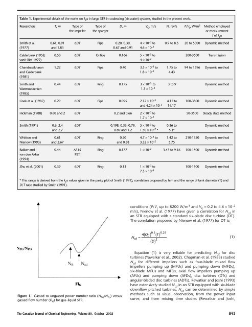
Table 1. Experimental details of the works on k L a <strong>in</strong> large STR <strong>in</strong> coalesc<strong>in</strong>g (air-water) systems, studied <strong>in</strong> the present work..<br />
Researchers T, m Type of Type of D, m V G , m/s N, rev/s P/V L , W/m 3 Method employed<br />
the impeller the sparger or measurement<br />
f of k L a<br />
Smith et al. 0.61, 0.91 6DT Pipe 0.20, 0.30, 4 ¥ 10 –3 to 0.9 to 8.5 20 to 5000 Dynamic method<br />
(1977) and 1.83 0.67 and 0.91 4.6 ¥ 10 –2<br />
Calderbank (1958; 0.50 6DT Orifice 0.166 5 ¥ 10 –3 to 300-3500 Transmission<br />
van’t Riet 1979) 4 ¥ 10 –2<br />
Chandrasekharan 1.22 6DT Pipe 0.40 3.5 ¥ 10 –3 to 1.75 to 94 to 1596 Dynamic method<br />
and Calderbank 1.8 ¥ 10 –2 4.43<br />
(1981)<br />
Smith and 0.44 6DT R<strong>in</strong>g 0.175 3 ¥ 10 –3 to 3 to 9 Dynamic method<br />
Warmoeskerken 1.3 ¥ 10 –2<br />
(1985)<br />
L<strong>in</strong>ek et al. (1987) 0.29 6DT Pipe 0.095 2.12 ¥ 10 –3 4.17 to 100-3500 Dynamic method<br />
and 4.24 ¥ 10 –3 14.17<br />
Hickman (1988) 0.60 and 2 6DT 0.2 and 0.66 2 ¥ 10 –3 to 50-3500 Steady state method<br />
1.7 ¥ 10 –2<br />
Smith (1991) 0.6, 2.4 6DT 0.198, 0.33, 0.79, 5 ¥ 10 –3 to 0.36 to Dynamic method<br />
and 2.7 0.89 and 1.2 1.50 ¥ 10 –2 * 5.1*<br />
Whitton and 0.61 6DT R<strong>in</strong>g 0.20 4.7 ¥ 10 –3 to 1.42 to 210-1350 Dynamic method<br />
Nienow (1993) and 2.67 and 0.88 3.32 ¥ 10 –2 5.75<br />
Bakker and 0.44 A315 R<strong>in</strong>g 0.177 1 ¥ 10 –2 3.43 to 9.16 100-1500 Dynamic method<br />
van den Akker PBT<br />
(1994)<br />
Zhu et al. (2001) 0.39 6DT R<strong>in</strong>g 0.13 1 ¥ 10 –3 to 100-1500 Dynamic method<br />
7.5 ¥ 10 –3<br />
* This range is derived from the k L a values given <strong>in</strong> the parity plot of Smith (1991), correlation proposed by him and the range of tank diameter (T) and<br />
D/T ratio studied by Smith (1991).<br />
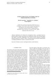
Figure 1. <strong>Gas</strong>sed to ungassed power number ratio (N PG /N Po ) versus<br />
gassed flow number (Fl G ) for gas–liquid STR.<br />
conditions (P/V L up to 8200 W/m 3 and V G = 0.2 to 4.6 ¥ 10 –2<br />
m/s), Nienow et al. (1977) have given a correlation for N cd <strong>in</strong><br />
an STR equipped with a standard six-blade disc turb<strong>in</strong>e (DT).<br />
The correlation proposed by Nienow et al. (1977) for DT is:<br />
( )<br />
QGT Ncd<br />
=<br />
D<br />
( ) ( )<br />
05 . 025 .<br />
4<br />
2<br />
Equation (1) is very reliable for predict<strong>in</strong>g N cd for disc<br />
turb<strong>in</strong>es (Yawalkar et al., 2002). Chapman et al. (1983) studied<br />
N cd for different impellers such as four-blade mixed flow<br />
impellers pump<strong>in</strong>g up (MFUs) and pump<strong>in</strong>g down (MFDs),<br />
six-blade MFUs and MFDs, axial flow impellers pump<strong>in</strong>g up<br />
(AFUs) and pump<strong>in</strong>g down (AFDs), disc turb<strong>in</strong>es (DTs) and<br />
angular-bladed disc turb<strong>in</strong>es (ADTs). Rewatkar and Joshi (1993)<br />
have extensively studied N cd <strong>in</strong> an STR equipped with six-blade<br />
downflow pitched turb<strong>in</strong>es. N cd can be determ<strong>in</strong>ed by simple<br />
methods such as visual observation, from the power <strong>in</strong>put<br />
curve, and from mix<strong>in</strong>g time studies (Rewatkar and Joshi,<br />
The Canadian Journal of Chemical Eng<strong>in</strong>eer<strong>in</strong>g, Volume 80, October 2002 841<br />
(1)