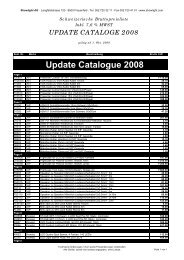
standard & heavy duty line
standard & heavy duty line
standard & heavy duty line

You also want an ePaper? Increase the reach of your titles
YUMPU automatically turns print PDFs into web optimized ePapers that Google loves.
QL76PR<br />
HIGH LOAD LINE<br />
Span Point Full Central Point Full Central Point Full Central Point Full Central Load Full Central<br />
Load Load Deflection Load Load Deflection Load Load Deflection Load Load Deflection Load Deflection<br />
[m] [kg] [kg] [mm] [kg] [kg] [mm] [kg] [kg] [mm] [kg] [kg] [mm] [kg/m] [kg] [mm]<br />
2,5 2974 2974 0,5 1550 3101 0,4 1056 3167 0,4 801 3203 0,4 1338 3344 0,3<br />
5 2578 2578 3 1401 2803 3 975 2924 3 750 3001 3 659 3296 3<br />
7,5 2247 2247 10 1264 2529 10 898 2693 10 701 2803 9 433 3244 9<br />
10 1975 1975 21 1143 2286 21 827 2480 21 653 2610 21 320 3200 22<br />
12,5 1650 1650 36 1036 2071 38 761 2282 39 608 2433 39 252 3148 42<br />
15 1401 1401 54 939 1877 61 700 2100 63 565 2261 65 207 3100 73<br />
17,5 1204 1204 77 818 1636 87 644 1933 95 515 2059 96 161 2813 107<br />
20 1043 1043 104 715 1430 119 572 1716 130 444 1778 129 120 2400 141<br />
22,5 906 906 136 627 1255 155 493 1478 167 385 1541 166 92 2067 181<br />
25 790 790 174 551 1102 197 426 1278 209 335 1339 209 71 1778 224<br />
Load table has been prepared in accordance with UNI ENV 1999-1-1 (Eurocode 9).<br />
When calculating the allowable loads shown in the table, it is assumed that the trusses are simply supported at the end connection and that static<br />
loads will be applied to the node points.<br />
The application of the load shall be on the centre <strong>line</strong> of the truss.<br />
The values shown in the table are the allowable static loads that can be applied to the truss. This is the live load or the payload.<br />
The self weight of the truss has been taken into account when calculating the values in the table.<br />
It should be noted that this are idealised loading conditions and the User shall re-analyze the truss for the loading conditions which prevail for the<br />
application being considered.<br />
Lasttabelle wurde in Übereinstimmung mit UNI EV 1999-1-1 (Eurocode 9) vorbereitet.<br />
Bei der Berechnung der in der Tabelle genannten zulässigen Lasten wird davon ausgegangen, dass die Traversen an den Endpunkten aufliegen und<br />
an den Knotenpunkten statische Lasten angebracht werden.<br />
Die Last soll an der Mittelachse der Traverse angebracht sein.<br />
Die in der Tabelle genannten Werte entsprechen den zulässigen statischen Lasten, die an die Traverse gehängt werden dürfen. Das ist die Nutzlast.<br />
Bei der Berechnung der in der Tabelle genannten Werte wurde das Eigengewicht der Traverse mit berücksichtigt.<br />
Wir weisen darauf hin, dass dies theoretisch optimale Lastbedingungen sind und dass der Anwender die Traverse nochmals für den vorgesehenen<br />
Einsatzzweck überprüfen sollte.<br />
Full Load [kg]<br />
4000<br />
3500<br />
3000<br />
2500<br />
2000<br />
1500<br />
1000<br />
500<br />
0<br />
Centre Point Load<br />
(C.P.L.)<br />
Load Table<br />
Third Point Load<br />
(T.P.L.)<br />
Quarter Point Load<br />
(Q.P.L.)<br />
Fifth Point Load<br />
(F.P.L.)<br />
2,5 5,0 7,5 10,0 12,5 15,0 17,5 20,0 22,5 25,0<br />
Span [m]<br />
Uniformly Distributed Load<br />
(U.D.L.)<br />
U.D.L.<br />
C.P.L.<br />
T.P.L.<br />
Q.P.L.<br />
F.P.L.<br />
K<br />
K<br />
071