A Design Tool for Aerodynamic Lens Systems - Department of ...
A Design Tool for Aerodynamic Lens Systems - Department of ...
A Design Tool for Aerodynamic Lens Systems - Department of ...

Create successful ePaper yourself
Turn your PDF publications into a flip-book with our unique Google optimized e-Paper software.
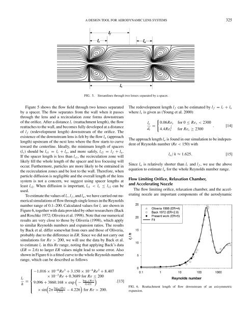
Figure 5 shows the flow field through two lenses separated<br />
by a spacer. The flow separates from the wall when it passes<br />
through the lens and a recirculation zone <strong>for</strong>ms downstream<br />
<strong>of</strong> the orifice. After a distance lr (reattachment length), the flow<br />
reattaches to the wall, and becomes fully developed at a distance<br />
<strong>of</strong> l f (redevelopment length) downstream <strong>of</strong> the orifice. The<br />
existence <strong>of</strong> the downstream lens is felt by the flow la (approach<br />
length) upstream <strong>of</strong> the next lens where the flow starts to curve<br />
toward the centerline. Ideally, the minimum length <strong>of</strong> spacers<br />
(ls) should be ls1 = lr + la, and more safely, ls2 = l f + la.<br />
If the spacer length is less than ls1, the recirculation zone will<br />
likely fill the whole length <strong>of</strong> the spacer and less focusing will<br />
occur. Furthermore, particles are more likely to be entrained in<br />
the recirculation zones and be lost to the wall. There<strong>for</strong>e, when<br />
particle diffusion is negligible and the overall length <strong>of</strong> the lens<br />
system is not a concern, we suggest using spacer lengths at<br />
least ls2. When diffusion is important, ls1 < ls ≤ ls2 can be<br />
used.<br />
To estimate the values <strong>of</strong> lr, l f , and la,wehave carried out numerical<br />
simulations <strong>of</strong> flow through single lenses in the Reynolds<br />
number range <strong>of</strong> 0.1–200. Calculated values <strong>for</strong> lr are shown in<br />
Figure 6, together with data provided by other researchers (Back<br />
and Roschke 1972; Oliveira et al. 1998). Note that our numerical<br />
results are very close to those by Oliveria (1998), which apply<br />
to similar Reynolds numbers and expansion ratios. The results<br />
by Back et al. differ somewhat from ours and those <strong>of</strong> Oliveria,<br />
probably due to the difference in ER. Since we did not carry out<br />
simulations <strong>for</strong> Re > 200, we will use the data by Back et al.<br />
to estimate lr in this Re range, noting that applying Back’s data<br />
(ER = 2.6) to larger ER values might lead to some error. Also<br />
shown in Figure 6 is a fitted curve to the whole Reynolds number<br />
range, which can be described as follows<br />
lr<br />
h =<br />
⎧<br />
−1.016 × 10<br />
⎪⎨<br />
⎪⎩<br />
−6 Re3 + 3.150 × 10⁻⁴ Re2 + 8.407<br />
× 10−2 Re + 0.3689<br />
�<br />
<strong>for</strong> Re ≤ 200<br />
9.096 + 3860.168 × exp − log10 (Re)<br />
�<br />
.[13]<br />
�<br />
� 0.431<br />
× sin − 4.226 <strong>for</strong> Re > 200.<br />
2π log 10 (Re)<br />
1.272<br />
A DESIGN TOOL FOR AERODYNAMIC LENS SYSTEMS 325<br />
FIG. 5. Streamlines through two lenses separated by a spacer.<br />
The redevelopment length l f can be estimated by l f = lr + le<br />
where le is given as (Young et al. 2000)<br />
le<br />
dt<br />
�<br />
0.06Res <strong>for</strong> 0 ≤ Res < 2300<br />
=<br />
. [14]<br />
<strong>for</strong> Res ≥ 2300<br />
4.4Re 1<br />
6<br />
s<br />
The approach length la is found in our simulation to be independent<br />
<strong>of</strong> Reynolds number (Re < 150) with<br />
la/h ≈ 1.625. [15]<br />
Since la is relatively shorter than lr and l f ,weuse the above<br />
equation to estimate la <strong>for</strong> the whole Reynolds number range.<br />
Flow Limiting Orifice, Relaxation Chamber,<br />
and Accelerating Nozzle<br />
The flow limiting orifice, relaxation chamber, and the accelerating<br />
nozzle are important components <strong>of</strong> the aerodynamic<br />
FIG. 6. Reattachment length <strong>of</strong> flow downstream <strong>of</strong> an axisymmetric<br />
expansion.