A Design Tool for Aerodynamic Lens Systems - Department of ...
A Design Tool for Aerodynamic Lens Systems - Department of ...
A Design Tool for Aerodynamic Lens Systems - Department of ...

You also want an ePaper? Increase the reach of your titles
YUMPU automatically turns print PDFs into web optimized ePapers that Google loves.
326 X. WANG AND P. H. MCMURRY<br />
lens system. The flow limiting orifice and relaxation chamber<br />
are required if the particle source pressure is higher than the<br />
lens operating pressure. The orifice sets the volumetric flowrate<br />
through the lens system, and reduces the pressure to the lens<br />
operating pressure. Usually the flow through the flow limiting<br />
orifice is critical. There<strong>for</strong>e, a relaxation chamber is needed to<br />
slow down the high velocity flow and particles to prevent particle<br />
impaction on the downstream lens. The relaxation chamber<br />
also provides space <strong>for</strong> the flow to reattach to the wall after the<br />
recirculation eddies downstream <strong>of</strong> the orifice. The accelerating<br />
nozzle controls the exact lens operating pressure, and it accelerates<br />
particles to a downstream destination with minimized<br />
divergence angles.<br />
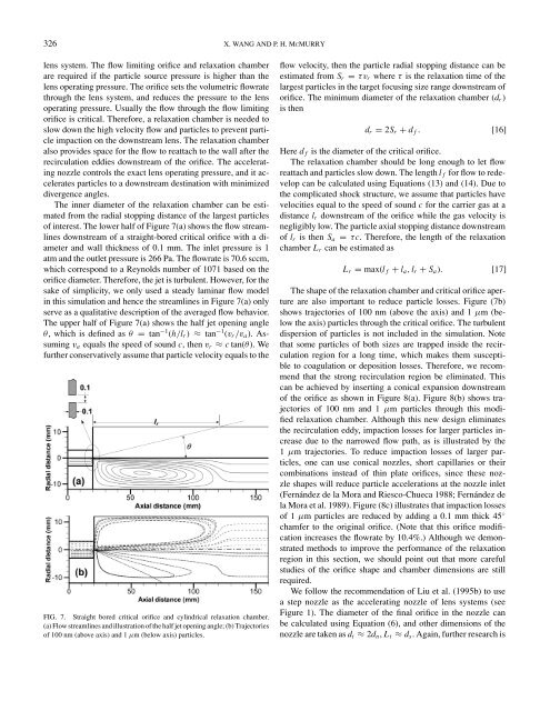
The inner diameter <strong>of</strong> the relaxation chamber can be estimated<br />
from the radial stopping distance <strong>of</strong> the largest particles<br />
<strong>of</strong> interest. The lower half <strong>of</strong> Figure 7(a) shows the flow streamlines<br />
downstream <strong>of</strong> a straight-bored critical orifice with a diameter<br />
and wall thickness <strong>of</strong> 0.1 mm. The inlet pressure is 1<br />
atm and the outlet pressure is 266 Pa. The flowrate is 70.6 sccm,<br />
which correspond to a Reynolds number <strong>of</strong> 1071 based on the<br />
orifice diameter. There<strong>for</strong>e, the jet is turbulent. However, <strong>for</strong> the<br />
sake <strong>of</strong> simplicity, we only used a steady laminar flow model<br />
in this simulation and hence the streamlines in Figure 7(a) only<br />
serve as a qualitative description <strong>of</strong> the averaged flow behavior.<br />
The upper half <strong>of</strong> Figure 7(a) shows the half jet opening angle<br />
θ, which is defined as θ = tan −1 (h/lr) ≈ tan −1 (vr/va). Assuming<br />
va equals the speed <strong>of</strong> sound c, then vr ≈ c tan(θ). We<br />
further conservatively assume that particle velocity equals to the<br />
FIG. 7. Straight bored critical orifice and cylindrical relaxation chamber.<br />
(a) Flow streamlines and illustration <strong>of</strong> the half jet opening angle; (b) Trajectories<br />
<strong>of</strong> 100 nm (above axis) and 1 µm (below axis) particles.<br />
flow velocity, then the particle radial stopping distance can be<br />
estimated from Sr = τvr where τ is the relaxation time <strong>of</strong> the<br />
largest particles in the target focusing size range downstream <strong>of</strong><br />
orifice. The minimum diameter <strong>of</strong> the relaxation chamber (dr)<br />
is then<br />
dr = 2Sr + d f . [16]<br />
Here d f is the diameter <strong>of</strong> the critical orifice.<br />
The relaxation chamber should be long enough to let flow<br />
reattach and particles slow down. The length l f <strong>for</strong> flow to redevelop<br />
can be calculated using Equations (13) and (14). Due to<br />
the complicated shock structure, we assume that particles have<br />
velocities equal to the speed <strong>of</strong> sound c <strong>for</strong> the carrier gas at a<br />
distance lr downstream <strong>of</strong> the orifice while the gas velocity is<br />
negligibly low. The particle axial stopping distance downstream<br />
<strong>of</strong> lr is then Sa = τc. There<strong>for</strong>e, the length <strong>of</strong> the relaxation<br />
chamber Lr can be estimated as<br />
Lr = max(l f + la, lr + Sa). [17]<br />
The shape <strong>of</strong> the relaxation chamber and critical orifice aperture<br />
are also important to reduce particle losses. Figure (7b)<br />
shows trajectories <strong>of</strong> 100 nm (above the axis) and 1 µm (below<br />
the axis) particles through the critical orifice. The turbulent<br />
dispersion <strong>of</strong> particles is not included in the simulation. Note<br />
that some particles <strong>of</strong> both sizes are trapped inside the recirculation<br />
region <strong>for</strong> a long time, which makes them susceptible<br />
to coagulation or deposition losses. There<strong>for</strong>e, we recommend<br />
that the strong recirculation region be eliminated. This<br />
can be achieved by inserting a conical expansion downstream<br />
<strong>of</strong> the orifice as shown in Figure 8(a). Figure 8(b) shows trajectories<br />
<strong>of</strong> 100 nm and 1 µm particles through this modified<br />
relaxation chamber. Although this new design eliminates<br />
the recirculation eddy, impaction losses <strong>for</strong> larger particles increase<br />
due to the narrowed flow path, as is illustrated by the<br />
1 µm trajectories. To reduce impaction losses <strong>of</strong> larger particles,<br />
one can use conical nozzles, short capillaries or their<br />
combinations instead <strong>of</strong> thin plate orifices, since these nozzle<br />
shapes will reduce particle accelerations at the nozzle inlet<br />
(Fernández de la Mora and Riesco-Chueca 1988; Fernández de<br />
la Mora et al. 1989). Figure (8c) illustrates that impaction losses<br />
<strong>of</strong> 1 µm particles are reduced by adding a 0.1 mm thick 45 ◦<br />
chamfer to the original orifice. (Note that this orifice modification<br />
increases the flowrate by 10.4%.) Although we demonstrated<br />
methods to improve the per<strong>for</strong>mance <strong>of</strong> the relaxation<br />
region in this section, we should point out that more careful<br />
studies <strong>of</strong> the orifice shape and chamber dimensions are still<br />
required.<br />
We follow the recommendation <strong>of</strong> Liu et al. (1995b) to use<br />
a step nozzle as the accelerating nozzle <strong>of</strong> lens systems (see<br />
Figure 1). The diameter <strong>of</strong> the final orifice in the nozzle can<br />
be calculated using Equation (6), and other dimensions <strong>of</strong> the<br />
nozzle are taken as dt ≈ 2dn, Lt ≈ ds.Again, further research is