USS Fracture MIS. The minimally invasive Schanz Screw ... - Synthes
USS Fracture MIS. The minimally invasive Schanz Screw ... - Synthes
USS Fracture MIS. The minimally invasive Schanz Screw ... - Synthes

Create successful ePaper yourself
Turn your PDF publications into a flip-book with our unique Google optimized e-Paper software.
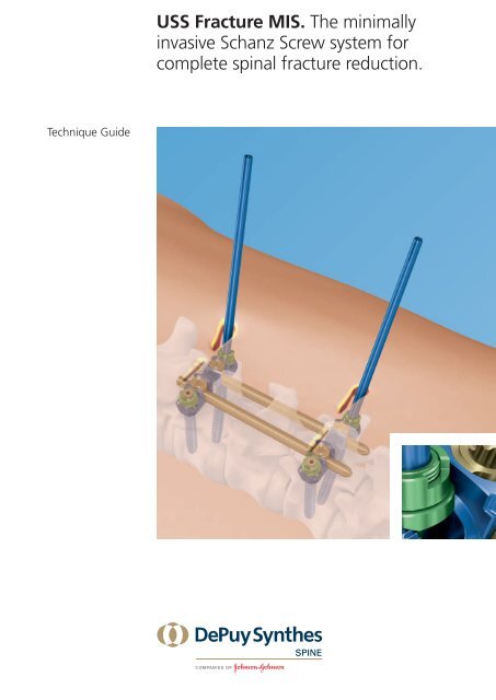
Technique Guide<br />
<strong>USS</strong> <strong>Fracture</strong> <strong>MIS</strong>. <strong>The</strong> <strong>minimally</strong><br />
<strong>invasive</strong> <strong>Schanz</strong> <strong>Screw</strong> system for<br />
complete spinal fracture reduction.
Image intensifier control<br />
Warning<br />
This description alone does not provide sufficient background for direct use of<br />
the instrument set. Instruction by a surgeon experienced in handling these<br />
instruments is highly recommended.<br />
Reprocessing, Care and Maintenance of<br />
<strong>Synthes</strong> Instruments<br />
For general guidelines, function control and dismantling of multi-part instruments,<br />
please contact your local sales representative or refer to:<br />
www.synthes.com/reprocessing
Table of Contents<br />
Introduction<br />
Surgical Technique<br />
Product Information<br />
<strong>USS</strong> <strong>Fracture</strong> <strong>MIS</strong> 2<br />
AO Principles 4<br />
Indications and Contraindications 5<br />
Preparation 6<br />
Pedicle Preparation 10<br />
<strong>Screw</strong> Insertion 16<br />
<strong>Fracture</strong> Clamp Insertion 22<br />
Rod Insertion 25<br />
Setting the Rod 30<br />
<strong>Fracture</strong> Reduction 36<br />
Final Tightening 41<br />
Removal of Instruments 42<br />
Trim <strong>Schanz</strong> <strong>Screw</strong>s 43<br />
Optional Techniques 44<br />
Augmentation of Perforated <strong>Schanz</strong> <strong>Screw</strong>s 44<br />
Tap pedicle 56<br />
Reduction of Spondylolisthesis 58<br />
Distraction with Rack Distractor 60<br />
Implant Removal 62<br />
Implants 70<br />
Instruments 74<br />
Sets 84<br />
<strong>USS</strong> <strong>Fracture</strong> <strong>MIS</strong> Technique Guide <strong>Synthes</strong> 1
<strong>USS</strong> <strong>Fracture</strong> <strong>MIS</strong>. <strong>The</strong> <strong>minimally</strong><br />
<strong>invasive</strong> <strong>Schanz</strong> <strong>Screw</strong> system for<br />
complete spinal fracture reduction.<br />
� <strong>Schanz</strong> screws<br />
– Enable active correction of the sagittal balance<br />
– Provide immediate tactile feedback<br />
– Dual Core design for screw adjustments without clinical<br />
relevant loss of bone purchase<br />
� <strong>Fracture</strong> clamps<br />
– Allow for independent kyphosis correction and distraction<br />
as per the AO technique<br />
– Top loading fracture clamp allows for easy rod<br />
introduction<br />
� Perforated <strong>Schanz</strong> screws for osteoporotic bone<br />
– Improved screw anchoring and vertebral body support<br />
due to cement cloud<br />
– Six radial openings for 360° cement distribution<br />
– Augmentation after final screw positioning<br />
� Percutaneous implantation<br />
– Less trauma and blood loss<br />
– Fast recovery<br />
� Adjustable rod holder<br />
– Allows for individual rod angulation during insertion<br />
– 6.0 mm diameter rods available in TAN<br />
� Percutaneous distraction and compression<br />
– Parallel distraction performed with bridge above the skin<br />
– Adjustability independent of previously performed sagittal<br />
correction<br />
� Percutaneous removal possible<br />
– Allows for restauration of motion segments after fracture<br />
healing<br />
2 <strong>Synthes</strong> <strong>USS</strong> <strong>Fracture</strong> <strong>MIS</strong> Technique Guide<br />
�
�<br />
�<br />
�<br />
�<br />
�<br />
�<br />
�<br />
<strong>USS</strong> <strong>Fracture</strong> <strong>MIS</strong> Technique Guide <strong>Synthes</strong> 3
AO Principles<br />
In 1958, the AO formulated four basic principles, which have<br />
1, 2<br />
become the guidelines for internal fixation.<br />
<strong>The</strong>y are:<br />
– Anatomic reduction<br />
– Stable internal fixation<br />
– Preservation of blood supply<br />
– Early, active mobilization<br />
<strong>The</strong> fundamental aims of fracture treatment in the limbs and<br />
fusion of the spine are the same. A specific goal in the spine<br />
is returning as much function as possible to the injured neural<br />
elements. 2<br />
AO Principles as Applied to the Spine 3<br />
Anatomic alignment<br />
Restoration of normal spinal alignment to improve the<br />
biomechanics of the spine.<br />
Stable internal fixation<br />
Stabilization of the spinal segment to promote bony fusion.<br />
Preservation of blood supply<br />
Creation of an optimal environment for fusion.<br />
Early, active mobilization<br />
Minimization of damage to the spinal vasculature, dura, and<br />
neural elements, which may contribute to pain reduction and<br />
improved function for the patient.<br />
1 Müller ME, Allgöwer M, Schneider R, Willenegger H (1995) Manual of<br />
Internal Fixation. 3rd, expanded and completely revised ed. 1991. Berlin,<br />
Heidelberg, New York: Springer<br />
2 Ibid.<br />
3 Aebi M, Arlet V, Webb JK (2007). AOSPINE Manual (2 vols.), Stuttgart, New York:<br />
Thieme<br />
4 <strong>Synthes</strong> <strong>USS</strong> <strong>Fracture</strong> <strong>MIS</strong> Technique Guide
Indications and Contraindications<br />
<strong>The</strong> <strong>USS</strong> <strong>Fracture</strong> <strong>MIS</strong> system is a posterior thoracolumbar<br />
pedicle screw fixation system (T1 – S2) intended to provide<br />
precise and segmental stabilization of the spine in skeletally<br />
mature patients. Surgery can be performed with either a<br />
<strong>minimally</strong> <strong>invasive</strong> or open approach.<br />
Indications<br />
– <strong>Fracture</strong>s: unstable fractures of the thoracic, lumbar and<br />
lumbosacral spine and fractures associated with unacceptable<br />
deformities (Discoligamentous disruptions or previous<br />
laminectomies do not constitute contraindications)<br />
– Tumors<br />
– Infections<br />
– Posttraumatic deformities<br />
– Spondylolisthesis<br />
– Degenerative Disc Disease<br />
– Osteoporosis when used concurrently with Vertecem V+<br />
Contraindications<br />
– In fractures and tumors with severe anterior body disruption,<br />
an additional anterior support or column reconstruction<br />
is required<br />
– Osteoporosis when used without augmentation<br />
– Severe Osteoporosis<br />
Contraindications related to Vertecem V+<br />
Please refer to the corresponding technique guide for the<br />
Vertecem V+ (036.000.895) system.<br />
<strong>USS</strong> <strong>Fracture</strong> <strong>MIS</strong> Technique Guide <strong>Synthes</strong> 5
Preparation<br />
1<br />
Patient positioning<br />
Position the patient on a radiolucent OR table in the prone<br />
position. To obtain optimal visualization of the spine, the OR<br />
table should have enough clearance available for a fluoroscopic<br />
C-arm to rotate freely for AP, oblique and lateral views.<br />
Accurate visualization of the anatomic landmarks and fluoroscopic<br />
visualization of the pedicles are imperative for using<br />
the <strong>USS</strong> <strong>Fracture</strong> <strong>MIS</strong> System.<br />
6 <strong>Synthes</strong> <strong>USS</strong> <strong>Fracture</strong> <strong>MIS</strong> Technique Guide
2<br />
General recommendations on<br />
Kirschner wire handling<br />
Ensure that the Kirschner wires remain securely in position<br />
throughout the entire duration of the procedure. Although<br />
the tips of the Kirschner wires are blunt, the Kirschner wires<br />
should be monitored under fluoroscopy to ensure they do<br />
not penetrate the anterior wall of the vertebral body and<br />
damage the vessels situated in front.<br />
Ensure that the Kirschner wires do not slip out before the<br />
screws are inserted. <strong>The</strong> Kirschner wires are long enough<br />
to be held in place by hand during pedicle preparation and<br />
soft tissue dilation.<br />
<strong>USS</strong> <strong>Fracture</strong> <strong>MIS</strong> Technique Guide <strong>Synthes</strong> 7
Preparation<br />
Recommendation for positioning the<br />
Kirschner wire<br />
When inserting the Kirschner wires, be mindful to position<br />
them as parallel as possible to each other and to the cranial<br />
endplates of the vertebrae.<br />
Note: When operating on L5/S1, position the Kirschner wires<br />
according to the green-colored Kirschner wire (see image).<br />
8 <strong>Synthes</strong> <strong>USS</strong> <strong>Fracture</strong> <strong>MIS</strong> Technique Guide
3<br />
Kirschner wire insertion<br />
Each Kirschner wire is placed through an individual incision.<br />
Kirschner wire insertion can be realized either using multiple<br />
(see “Pedicle Preparation”, step 1a) or single (see “Pedicle<br />
Preparation”, step 1b) use instruments.<br />
Technique tip: Bi-planar fluoroscopy with two C-arms<br />
facilitates a safer, easier and quicker radiographic assessment<br />
during the surgical procedure.<br />
<strong>USS</strong> <strong>Fracture</strong> <strong>MIS</strong> Technique Guide <strong>Synthes</strong> 9
Pedicle Preparation<br />
1a<br />
Prepare pedicle and insert Kirschner wire<br />
with multiple-use instruments<br />
Instruments<br />
02.606.003 Kirschner Wire � 1.6 mm without trocar<br />
tip, length 480 mm, Stainless Steel<br />
03.606.020 Trocar � 1.6 mm<br />
03.606.021 Trocar Holder, for No. 03.606.020<br />
03.620.230 Pedicle Probe � 3.5 mm, cannulated,<br />
radiolucent, length 253 mm,<br />
for <strong>Screw</strong>s � 5.0 to 7.0 mm<br />
Optional instruments<br />
03.616.070 Handle for Kirschner Wire � 1.6 mm<br />
03.627.029 Instrument Holder, radiolucent<br />
Use radiographic imaging to locate pedicles and the site of<br />
skin incision. With a scalpel, create an incision of approximately<br />
25 mm in length and bluntly dissect the subcutaneous<br />
tissue down to the pedicle.<br />
Use the pedicle awl to perforate the cortex and prepare the<br />
screw channel.<br />
<strong>Screw</strong> the trocar into the trocar holder (1,2). Fully tighten the<br />
assembly into the pedicle awl (3). Adjust the radio lucent<br />
sleeve to a length of 10 mm (4).<br />
Position the awl on the pedicle and open the cortex. Before<br />
the pedicle awl is advanced into the pedicle, the dedicated<br />
screw length can be determined using the radiolucent sleeve.<br />
10 <strong>Synthes</strong> <strong>USS</strong> <strong>Fracture</strong> <strong>MIS</strong> Technique Guide<br />
1<br />
3<br />
4<br />
2
Note: <strong>The</strong> tip of the advanced pedicle awl indicates the tip<br />
of the screw.<br />
Adjust the sleeve to match the dedicated screw length and<br />
advance the pedicle awl (5).<br />
Precaution: Use radiographic imaging to confirm orientation<br />
and depth while inserting the pedicle awl.<br />
Notes:<br />
– <strong>The</strong> sleeve prevents the awl from advancing further than<br />
the prescribed screw length thanks to a stop on the<br />
pedicle. For verification purposes, the sleeve tip is indicated<br />
with an x-ray marker (6).<br />
– Rotate the pedicle awl continuously while advancing it<br />
into the vertebra.<br />
Optional: Use the radiolucent instrument holder to hold<br />
the pedicle awl during radiographic imaging (6b).<br />
5<br />
6b<br />
<strong>USS</strong> <strong>Fracture</strong> <strong>MIS</strong> Technique Guide <strong>Synthes</strong> 11<br />
6
Pedicle Preparation<br />
Unscrew the trocar holder and the trocar from the pedicle<br />
awl, ensuring the awl remains in its position (7).<br />
12 <strong>Synthes</strong> <strong>USS</strong> <strong>Fracture</strong> <strong>MIS</strong> Technique Guide<br />
7
Insert a Kirschner wire into the awl and guide it through the<br />
pedicle (8). Advance the wire under fluoroscopic control<br />
to the dedicated depth where the screw is to be positioned.<br />
Optional: Use the handle for Kirschner wire to advance the<br />
wire. <strong>The</strong> handle for Kirschner wire is used either to advance<br />
or remove Kirschner wires during the procedure. <strong>The</strong> arrow<br />
on the instrument indicates the direction of Kirschner wire<br />
advancement or removal. Press the locking trigger and slip<br />
the instrument over the Kirschner wire. Release the trigger to<br />
lock the instrument at a position above the end of the<br />
cannulated awl.<br />
Warning: <strong>The</strong> distance between the instrument and the<br />
cannulated awl should be equal to the insertion depth of the<br />
Kirschner wire.<br />
Gently tap on the impaction surface of the Kirschner wire<br />
handle to advance the Kirschner wire. Observe the position<br />
under fluoroscopic control (9). Stop impacting when the<br />
instrument reaches the top of the cannulated awl.<br />
Remove the pedicle awl while maintaining the position of<br />
the Kirschner wire within the pedicle.<br />
Warnings:<br />
– To prevent inadvertent advancement of the Kirschner wire,<br />
align the trajectory of the probe with the Kirschner wire<br />
and monitor the Kirschner wire position using fluoroscopy<br />
– Proceed with small steps for the insertion of the Kirschner<br />
wire with the Kirschner wire handle. <strong>The</strong> distance<br />
between the Kirschner wire handle and the cannulated<br />
awl should be equal to the additional insertion depth of<br />
the Kirschner wire to avoid inadvertent advancement.<br />
Precaution: While removing the pedicle awl, secure the<br />
Kirschner wire at all times.<br />
Note: All <strong>USS</strong> <strong>Fracture</strong> <strong>MIS</strong> <strong>Schanz</strong> screws are self-tapping;<br />
however, if tapping is preferred, use the appropriate tap and<br />
tap handle.<br />
8<br />
9<br />
<strong>USS</strong> <strong>Fracture</strong> <strong>MIS</strong> Technique Guide <strong>Synthes</strong> 13
Pedicle Preparation<br />
1b<br />
Prepare pedicle and insert Kirschner wire<br />
with single-use instruments<br />
Instrument<br />
02.606.003 Kirschner Wire � 1.6 mm without trocar<br />
tip, length 480 mm, Stainless Steel<br />
Optional instruments<br />
03.616.070 Handle for Kirschner Wire � 1.6 mm<br />
03.627.029 Instrument Holder, radiolucent<br />
Note: Use radiographic imaging to locate pedicles and<br />
the site of skin incision.<br />
With a scalpel, create an incision of approximately 25 mm<br />
in length and bluntly dissect the subcutaneous tissue down<br />
to the pedicle.<br />
Insert a Jamshidi needle in the skin incision. Locate the entry<br />
point of the pedicle and align the Jamshidi needle with the<br />
pedicle trajectory. If necessary, reinsert and realign the needle<br />
(1).<br />
Open the cortex of the pedicle. Observe the position under<br />
fluoroscopic control.<br />
14 <strong>Synthes</strong> <strong>USS</strong> <strong>Fracture</strong> <strong>MIS</strong> Technique Guide<br />
1
Unscrew the trocar from the Jamshidi needle ensuring the<br />
needle remains in place.<br />
Insert a Kirschner wire into the Jamshidi needle and guide it<br />
through the pedicle (2). Advance the wire under fluoroscopic<br />
control to the dedicated depth where the screw is to be<br />
positioned.<br />
Note: Use radiographic imaging to confirm orientation and<br />
depth while inserting the Jamshidi needle.<br />
Technique tip: Use the handle for Kirschner wire to advance<br />
the wire (3; see Pedicle preparation, 1a for handling).<br />
Precaution: While removing the Jamshidi needle, secure<br />
the Kirschner wire at all times.<br />
Notes:<br />
– Enlarge screw channel with probe or tap prior to screw<br />
insertion.<br />
– All <strong>USS</strong> <strong>Fracture</strong> <strong>MIS</strong> <strong>Schanz</strong> screws are self-tapping; however,<br />
if tapping is preferred, use the appropriate tap and<br />
tap handle.<br />
2<br />
3<br />
<strong>USS</strong> <strong>Fracture</strong> <strong>MIS</strong> Technique Guide <strong>Synthes</strong> 15
<strong>Screw</strong> Insertion<br />
1<br />
Dilate incision and determine screw length<br />
Instruments<br />
03.610.001 Dilator � 1.8/10.0 mm, cannulated,<br />
for Guide Wire � 1.6 mm<br />
03.628.101 Dilator � 13 mm, eccentric,<br />
for No. 03.628.103<br />
03.628.103 Dilator � 10.0/13.0 mm,<br />
for No. 03.610.001<br />
02.606.003 Kirschner Wire � 1.6 mm<br />
without trocar tip, length 480 mm,<br />
Stainless Steel<br />
Optional instrument<br />
03.631.521 <strong>Screw</strong> Length Indicator<br />
Insert the 1.8/10.0 mm dilator over the Kirschner wire.<br />
Continue dilation placing the 10.0/13.0 mm dilator over the<br />
1.8/10.0 mm dilator. Subsequently place the 13.0 mm eccentric<br />
dilator over the 10.0/13.0 mm dilator, and orient the<br />
oblong part of the instrument on the side where the rod is<br />
going to be placed (1).<br />
Notes:<br />
– Use radiographic imaging to confirm orientation and<br />
depth of the Kirschner wire while inserting the dilators.<br />
Also use radiographic imaging to confirm that the dilators<br />
are placed as deep as possible, on the pedicle entry point.<br />
<strong>The</strong> eccentric dilator can be monitored thanks to a<br />
radiographic marker.<br />
– <strong>The</strong> handle for Kirschner wire may be used for Kirschner<br />
wire impaction (see “Pedicle Preparation”, step 1a).<br />
16 <strong>Synthes</strong> <strong>USS</strong> <strong>Fracture</strong> <strong>MIS</strong> Technique Guide<br />
1
Option: Use the <strong>MIS</strong> screw length indicator for determining<br />
the screw length.<br />
Note: <strong>The</strong> screw length indicator shows the depth of the<br />
Kirschner wire tip starting at the pedicle entry point. <strong>The</strong><br />
screw length is indicated by the thread length.<br />
Determine the screw length using the <strong>MIS</strong> screw length<br />
indicator on the top of the dilator (03.610.001) and the<br />
Kirschner wire. Read off the screw length between the<br />
double lines of the Kirschner wire (2).<br />
Remove the dilator 1.8/10.0 mm while carefully holding the<br />
Kirschner wire in place to ensure the pedicle entry point for<br />
screw placement is maintained (3).<br />
Leave dilator 10.0/13.0 mm and the 13.0 mm eccentric dilator<br />
in place to protect the surrounding tissue while inserting<br />
the pedicle screw.<br />
Precaution: While removing the dilators, secure the<br />
Kirschner wire at all times.<br />
2<br />
3<br />
<strong>USS</strong> <strong>Fracture</strong> <strong>MIS</strong> Technique Guide <strong>Synthes</strong> 17
<strong>Screw</strong> Insertion<br />
2<br />
Prepare and insert pedicle screws<br />
Instruments<br />
03.628.120 Spline Drive <strong>Screw</strong>driver,<br />
for <strong>Schanz</strong> <strong>Screw</strong>s, with T-Handle<br />
03.628.101 Dilator � 13 mm, eccentric,<br />
for No. 03.628.103<br />
03.628.103 Dilator � 10.0/13.0 mm,<br />
for No. 03.610.001<br />
Optional instruments<br />
03.627.024 Spline Drive <strong>Screw</strong>driver � 5.0 mm,<br />
for <strong>Schanz</strong> <strong>Screw</strong>s, cannulated,<br />
with Hexagonal Quick Coupling � 6.0 mm<br />
03.627.017 Torque-limiting Ratchet Handle, 7 Nm<br />
03.628.106 Reamer, cannulated<br />
Select the appropriate screw length. Choose screws with the<br />
maximum possible diameter and length to achieve maximum<br />
stability.<br />
Notes on the optional use of perforated <strong>Schanz</strong> screws:<br />
– If the screws are too short, the bone cement might be injected<br />
too close to the pedicle. It is required that the screw<br />
perforations are located in the vertebral body, close to the<br />
anterior cortical wall. For this reason, 35 mm screws<br />
should be placed in the sacrum only.<br />
− If the screws are too long, or placed bi-cortically, the anterior<br />
cortical wall may be penetrated and cement leakage<br />
might occur.<br />
Mount the <strong>Schanz</strong> screw into the self-holding spline drive<br />
screwdriver (1).<br />
18 <strong>Synthes</strong> <strong>USS</strong> <strong>Fracture</strong> <strong>MIS</strong> Technique Guide<br />
1
Match the screw axis to the Kirschner wire axis by passing<br />
the <strong>Schanz</strong> screw/spline drive screwdriver assembly over<br />
the Kirschner wire through the dilator � 10.0/13.0 mm until<br />
the tip of the screw reaches the pedicle entry point (2).<br />
Note: Visualize the insertion depth of the <strong>Schanz</strong> screw by<br />
inserting the screw until the etched line on the spline drive<br />
screwdriver is flush with the edge of the dilator (2).<br />
Carefully advance the screw in the pedicle until the screw tip<br />
passes through the pedicle.<br />
Control the Kirschner wire exiting the proximal end of the<br />
spline drive screwdriver.<br />
Remove the Kirschner wire once the tip of the screw enters<br />
the vertebral body.<br />
Detach the spline drive screwdriver from the <strong>Schanz</strong> screw<br />
and remove the dilators (3).<br />
3<br />
<strong>USS</strong> <strong>Fracture</strong> <strong>MIS</strong> Technique Guide <strong>Synthes</strong> 19<br />
2
<strong>Screw</strong> Insertion<br />
Notes on the optional use of perforated <strong>Schanz</strong> screws:<br />
– If perforated <strong>Schanz</strong> screws are used, assess the cortical<br />
shell for perforations.<br />
– In case of any perforation, special caution is required<br />
when bone cement is applied. Cement leakage and its<br />
related risks may compromise the physical condition of<br />
the patient.<br />
– <strong>The</strong> perforated <strong>Schanz</strong> screw must enter in approximately<br />
80% of the vertebral body (4).<br />
Notes and Warnings:<br />
– Monitor the tip of the Kirschner wire under image<br />
intensifier control to ensure that it does not penetrate the<br />
anterior wall of the vertebral body.<br />
– To prevent inadvertent advancement of the Kirschner wire,<br />
align the trajectory of the implant with the Kirschner wire<br />
and monitor the Kirschner wire position under image<br />
intensifier control.<br />
– During screw insertion, use the image intensifier to<br />
confirm screw trajectory and depth. <strong>The</strong> tip of the <strong>Schanz</strong><br />
screw must not penetrate the anterior wall of the<br />
vertebral body. <strong>The</strong> end of the thread of the <strong>Schanz</strong> screw<br />
must be flush with the pedicle entry point.<br />
– Pay attention when using cannulated instruments in combination<br />
with Kirschner wires (e.g. screwdrivers, awls etc.).<br />
Ensure that the exit point for the Kirschner wire in the<br />
instrument is not covered, to avoid pinching of the glove.<br />
– Guided screw placement is required to avoid misplacement<br />
of screws.<br />
– If tapping is optionally done before screw insertion, use<br />
the corresponding protection sleeve to protect soft tissue.<br />
20 <strong>Synthes</strong> <strong>USS</strong> <strong>Fracture</strong> <strong>MIS</strong> Technique Guide<br />
4
Optional technique<br />
To prepare the site of the <strong>MIS</strong> fracture clamp, insert the<br />
reamer over the implanted <strong>Schanz</strong> screw. Rotate the reamer<br />
to remove all interfering bone (5). Repeat for each <strong>Schanz</strong><br />
screw.<br />
Warnings:<br />
– Do not use the reamer through the dilator.<br />
– Anatomical structures might be damaged when using the<br />
reamer; use the image intensifier and take special care to<br />
protect the facet joints.<br />
5<br />
<strong>USS</strong> <strong>Fracture</strong> <strong>MIS</strong> Technique Guide <strong>Synthes</strong> 21
<strong>Fracture</strong> Clamp Insertion<br />
1<br />
Load <strong>MIS</strong> fracture clamp<br />
Instruments<br />
03.628.105 Clamp Holder<br />
03.628.113 Socket Wrench Shaft with 3-Lobe-Drive<br />
68.628.323 Module for <strong>Fracture</strong> Clamp and <strong>Schanz</strong><br />
<strong>Screw</strong>s, with Loading Station, with Lid,<br />
without Contents<br />
Properly position the <strong>MIS</strong> fracture clamp into the loading station<br />
(1) of the Modular Tray for <strong>Fracture</strong> Clamp and <strong>Schanz</strong><br />
<strong>Screw</strong>s (03.628.323). Ensure that the <strong>MIS</strong> fracture clamp can<br />
angulate freely by untightening the nut of the <strong>MIS</strong> fracture<br />
clamp with the socket wrench shaft by two revolutions.<br />
Align the blades of the clamp holder with the <strong>MIS</strong> fracture<br />
clamp and slide down into the loading station to snap a <strong>MIS</strong><br />
fracture clamp with the clamp holder (1).<br />
Press down firmly to capture the <strong>MIS</strong> fracture clamp. Ensure<br />
that the <strong>MIS</strong> fracture clamp is firmly attached to the instrument<br />
(2).<br />
Repeat this step for all clamps needed.<br />
22 <strong>Synthes</strong> <strong>USS</strong> <strong>Fracture</strong> <strong>MIS</strong> Technique Guide<br />
1<br />
2
Notes:<br />
– If the <strong>MIS</strong> fracture clamp does not snap into the clamp<br />
holder, gently pinch the blades of the clamp holder while<br />
pressing on the implant until it snaps.<br />
– In case of <strong>MIS</strong> fracture clamp disassembling, ensure the<br />
correct reassembling of the implant, with the orientation<br />
of the washer and of the nut according to the picture (3).<br />
– Check by pulling the clamp holder / <strong>MIS</strong> fracture clamp<br />
assembly construct to ensure a secure attachment.<br />
– Remove all implants from the loading station for cleaning<br />
and sterilization purposes. Implants must be stored in the<br />
corresponding pockets of the module.<br />
3<br />
<strong>USS</strong> <strong>Fracture</strong> <strong>MIS</strong> Technique Guide <strong>Synthes</strong> 23
<strong>Fracture</strong> Clamp Insertion<br />
2<br />
Insert fracture clamp<br />
Instrument<br />
03.628.105 Clamp Holder<br />
Insert the assembly (<strong>MIS</strong> fracture clamp attached to the<br />
clamp holder) over <strong>Schanz</strong> screw and through the skin<br />
incision.<br />
Position the clamp holder to receive the rod according to<br />
the planned position of the rod.<br />
Repeat this step for all <strong>Schanz</strong> screws.<br />
Notes:<br />
– Ensure that the <strong>MIS</strong> fracture clamp is seated as deep as<br />
possible, close to the pedicle entry (2); the reamer can be<br />
used according to the optional technique on page 21.<br />
– Ensure that the <strong>MIS</strong> fracture clamp can angulate freely.<br />
24 <strong>Synthes</strong> <strong>USS</strong> <strong>Fracture</strong> <strong>MIS</strong> Technique Guide<br />
1<br />
2
Rod Insertion<br />
1<br />
Determine rod length<br />
Instruments<br />
03.628.105 Clamp Holder<br />
03.628.107 Rod Length Indicator<br />
Introduce the rod length indicator through the holes of the<br />
clamp holders. Keep the clamp holders parallel during<br />
introduction (1) and slide the rod length indicator until the<br />
instrument is fully inserted (2).<br />
Read the corresponding rod length on the scale (3).<br />
<strong>The</strong> rod length indicator is removed by pushing back the<br />
instrument while keeping the clamp holders parallel.<br />
Notes:<br />
– To determine the rod length most precisely, align the<br />
clamp holders as parallel as possible.<br />
– To determine the length of the rod in case of distraction,<br />
add the desired distraction’s length to the length<br />
determined with the instrument.<br />
1<br />
2<br />
3<br />
<strong>USS</strong> <strong>Fracture</strong> <strong>MIS</strong> Technique Guide <strong>Synthes</strong> 25
Rod Insertion<br />
2<br />
Prepare the implant holder<br />
Instruments<br />
03.631.537 Handle for Rod Holder<br />
03.631.538 Rod Holder, straight<br />
Mount the handle of the rod holder and lock it (1).<br />
Note: Do not squeeze the trigger of the handle while<br />
mounting the handle.<br />
Ensure to pull back the locking sleeve and that the distal end<br />
of the rod holder shaft is visible.<br />
Snap the rod into the corresponding interface at the distal<br />
part of the rod holder (2).<br />
Precaution: When loading the rod, do not press the trigger<br />
of the handle.<br />
26 <strong>Synthes</strong> <strong>USS</strong> <strong>Fracture</strong> <strong>MIS</strong> Technique Guide<br />
1<br />
2
Press the push button of the rod holder and simultaneously<br />
press down the locking sleeve (3). Ensure that the rod is<br />
firmly connected (4).<br />
3<br />
4<br />
<strong>USS</strong> <strong>Fracture</strong> <strong>MIS</strong> Technique Guide <strong>Synthes</strong> 27
Rod Insertion<br />
3<br />
Insertion of rod<br />
Instruments<br />
03.631.537 Handle for Rod Holder<br />
03.631.538 Rod Holder, straight<br />
Align the slots of the clamp holders prior to rod insertion.<br />
Introduce the rod with a steep angle through slot of the<br />
most cranial or caudal clamp holder. <strong>The</strong> fixation of the rod<br />
angulation is achieved by squeezing the handle of the rod<br />
holder. Navigate the rod through the neighboring implants.<br />
If increased resistance is felt, verify under image intensifier<br />
control whether the rod has passed through or is placed below<br />
the fascia.<br />
Note: Check the depth of the tip of the rod with lateral<br />
imaging.<br />
28 <strong>Synthes</strong> <strong>USS</strong> <strong>Fracture</strong> <strong>MIS</strong> Technique Guide
4<br />
Verify rod placement<br />
Instrument<br />
03.628.124 Rod Indicator<br />
Verify the placement of the rod by introducing the rod<br />
indicator through the clamp holder (1).<br />
Notes:<br />
– Use the rod indicator to verify the presence of the rod in<br />
the implant. <strong>The</strong> visible black marking indicates the presence<br />
of the rod in the clamp holder or <strong>MIS</strong> fracture clamp<br />
(2). If the black marking disappears into the clamp holder,<br />
no rod is in place (3). Alternatively, verify rod placement<br />
through the adjacent clamp holder by attempting to<br />
rotate the clamp holders or under visual control.<br />
– Check final rod placement with lateral radiographic<br />
imaging. Ensure that the coupling and the tip of the rod<br />
protrude outside the <strong>MIS</strong> fracture clamps.<br />
1<br />
2 3<br />
<strong>USS</strong> <strong>Fracture</strong> <strong>MIS</strong> Technique Guide <strong>Synthes</strong> 29
Setting the Rod<br />
1<br />
Load locking cap<br />
Instruments<br />
03.628.108 Guide for Locking Cap<br />
68.628.323 Module for <strong>Fracture</strong> Clamp and<br />
<strong>Schanz</strong> <strong>Screw</strong>s, with Loading Station,<br />
with Lid, without Contents<br />
Properly position the <strong>MIS</strong> locking cap into the loading unit<br />
(1) of the Modular Tray for <strong>MIS</strong> <strong>Fracture</strong> Clamp and <strong>Schanz</strong><br />
<strong>Screw</strong>s (03.628.323). Properly orient and position the guide<br />
for locking cap over the locking cap on the loading unit (2).<br />
Note: Ensure the correct positioning of the <strong>MIS</strong> locking cap<br />
according to the etchings on the loading unit.<br />
Press down firmly to capture the locking cap (2).<br />
30 <strong>Synthes</strong> <strong>USS</strong> <strong>Fracture</strong> <strong>MIS</strong> Technique Guide<br />
1<br />
2
<strong>The</strong> locking cap will snap into the distal tip of the guide for<br />
locking cap (3).<br />
3<br />
<strong>USS</strong> <strong>Fracture</strong> <strong>MIS</strong> Technique Guide <strong>Synthes</strong> 31
Setting the Rod<br />
2<br />
Insert locking cap<br />
Instruments<br />
03.628.108 Guide for Locking Cap<br />
03.628.109 Persuader<br />
Insert the guide for locking cap into the clamp holder (1).<br />
Push down the guide for locking cap to press down the rod<br />
in the designated notch of the <strong>MIS</strong> fracture clamp. <strong>The</strong> last<br />
20 mm of the insertion are supported by a ratchet mechanism<br />
and avoid the sliding back of the guide for locking cap.<br />
32 <strong>Synthes</strong> <strong>USS</strong> <strong>Fracture</strong> <strong>MIS</strong> Technique Guide<br />
1
Position the persuader on the shoulders of the guide for<br />
locking cap and underneath the shoulder of the clamp<br />
holder (2) and squeeze the handle until the stop (3).<br />
Notes:<br />
– Ensure that the <strong>MIS</strong> fracture clamp is seated as deep as<br />
possible, close to the pedicle entry.<br />
– To remove the guide for locking cap, press the push<br />
button on the clamp holder.<br />
2<br />
3<br />
<strong>USS</strong> <strong>Fracture</strong> <strong>MIS</strong> Technique Guide <strong>Synthes</strong> 33
Setting the Rod<br />
3<br />
Rod fixation and removal of rod holder<br />
Instruments<br />
03.628.112 <strong>Screw</strong>driver for Locking Cap, T25<br />
03.628.114 Handle with Hexagonal Coupling<br />
� 7.0 mm<br />
03.631.537 Handle for Rod Holder<br />
03.631.538 Rod Holder, straight<br />
Optional instrument<br />
03.628.110 Counter Torque<br />
Insert the screwdriver for locking cap through the guide<br />
for locking cap. Hand-tighten the <strong>MIS</strong> locking cap with the<br />
handle positioned on the screwdriver. Leave the screwdriver<br />
in place until final tightening is accomplished.<br />
Repeat this procedure for all locking caps.<br />
Note: Check rod placement under lateral radiographic imaging.<br />
Ensure that the coupling and the tip of the rod protrude<br />
outside the <strong>MIS</strong> fracture clamps. Also ensure that the length<br />
of the rod inserted allows for potential distraction.<br />
34 <strong>Synthes</strong> <strong>USS</strong> <strong>Fracture</strong> <strong>MIS</strong> Technique Guide
Removal of rod holder<br />
Before removing the rod holder, ensure that the rod is securely<br />
fixed in the <strong>MIS</strong> fracture clamp adjacent to the clamp<br />
holder; use the handle with hexagonal coupling to handtighten<br />
the <strong>MIS</strong> locking cap and fix the rod.<br />
To remove the rod holder (1), press the push button � and<br />
slide up the locking sleeve �. For the removal of the rod<br />
holder, squeeze the handle and simultaneously pull up the<br />
rod holder (2).<br />
Notes:<br />
– Do not remove the rod holder and keep the rod attached<br />
to the rod holder as long as control over the position of<br />
the rod is required. Optionally, a second rod holder can be<br />
made available for the system.<br />
– If the rod holder has been removed, do not untighten the<br />
locking cap that was adjacent to the rod holder at any<br />
time during surgery.<br />
– <strong>The</strong> handle of the rod holder can be dismantled by tilting<br />
the lever on the side of the handle downward to the open<br />
position.<br />
– Do not try to reattach the rod to the rod holder in situ.<br />
1<br />
2<br />
�<br />
�<br />
<strong>USS</strong> <strong>Fracture</strong> <strong>MIS</strong> Technique Guide <strong>Synthes</strong> 35
<strong>Fracture</strong> Reduction<br />
1<br />
Kyphosis correction with the <strong>MIS</strong> fracture clamps<br />
fixed on the rod<br />
Instruments<br />
03.628.113 Socket Wrench Shaft with 3-Lobe-Drive<br />
03.628.112 <strong>Screw</strong>driver for Locking Cap, T25<br />
03.628.114 Handle with Hexagonal Coupling<br />
� 7.0 mm<br />
Ensure that all the <strong>MIS</strong> fracture clamps are positioned as<br />
deep as possible (see “<strong>Fracture</strong> Clamp Insertion”, Step 2 on<br />
page 24).<br />
Ensure that all <strong>MIS</strong> locking caps are hand-tightened to secure<br />
the distance between the <strong>MIS</strong> fracture clamps on the rod.<br />
Place the socket wrench shafts on the four <strong>Schanz</strong> screws.<br />
First connect the handles with hexagonal coupling to the<br />
socket wrench shafts on both caudal <strong>Schanz</strong> screws and<br />
lordose the spine (1). Tilt both posteriorly projecting caudal<br />
screws cranially to lordose the spine �.<br />
Secure the <strong>MIS</strong> fracture clamps / <strong>Schanz</strong> screws in the desired<br />
position by mounting the handle with hexagonal<br />
coupling on the socket wrench shaft to tighten the nut �.<br />
Locate the handles with hexagonal coupling on the socket<br />
wrench shafts on both cranial <strong>Schanz</strong> screws and lordose the<br />
spine (2). Tilt both posteriorly projecting cranial screws caudally<br />
to complete the lordosing operation � and secure in<br />
the desired position �.<br />
36 <strong>Synthes</strong> <strong>USS</strong> <strong>Fracture</strong> <strong>MIS</strong> Technique Guide<br />
1<br />
2<br />
�<br />
�<br />
�<br />
�
Notes:<br />
– For further manipulations, leave the socket wrench shafts<br />
in place until final tightening has been accomplished. To<br />
control the desired instrument (socket wrench shaft or<br />
screwdriver), only exchange the handles with hexagonal<br />
coupling.<br />
– Ensure that the <strong>MIS</strong> fracture clamp is positioned correctly<br />
on the shaft of the <strong>Schanz</strong> screw by controlling the height<br />
with the window within the socket wrenches. <strong>The</strong> range<br />
limit is when the top of the screw is flush with the window<br />
(3). A wrong position of the clamp on the screw<br />
is identifiable when the screw is visible in the window (4).<br />
In this case, check the screw insertion depth according to<br />
p.18 –19 (except for <strong>MIS</strong> <strong>Schanz</strong> screw perforated) or / and<br />
correct the height of the <strong>MIS</strong> fracture clamp with the<br />
clamp holder.<br />
3 4<br />
<strong>USS</strong> <strong>Fracture</strong> <strong>MIS</strong> Technique Guide <strong>Synthes</strong> 37
<strong>Fracture</strong> Reduction<br />
2<br />
Distraction (optional)<br />
Instruments<br />
03.627.008 Distraction Instrument for <strong>MIS</strong><br />
03.627.077 Distraction Forceps for <strong>MIS</strong><br />
03.628.113 Socket Wrench Shaft with 3-Lobe-Drive<br />
03.628.114 Handle with Hexagonal Coupling<br />
� 7.0 mm<br />
Ensure that all the nuts of the <strong>MIS</strong> fracture clamps are provisionally<br />
tightened and positioned as deep as possible (see<br />
“<strong>Fracture</strong> Clamp Insertion”, Step 2 on page 24)<br />
Assemble the distraction instrument onto the upper part of<br />
the ridged section of both socket wrench shafts and ensure a<br />
firm connection of the instrument to the socket wrench shaft<br />
(1–3). <strong>The</strong> clamps of the distraction instrument need to be<br />
positioned as high as possible on the ridged section of the<br />
socket wrenches. Verify that the connecting bar clicks audibly<br />
into the clamps. Fix the connecting bar in the clamps by<br />
closing the lever (1–3).<br />
38 <strong>Synthes</strong> <strong>USS</strong> <strong>Fracture</strong> <strong>MIS</strong> Technique Guide<br />
1<br />
2
Place the handle with hexagonal coupling on the screwdriver<br />
and loosen the locking cap of the <strong>MIS</strong> fracture clamp on the<br />
side of the rod with bullet nose (4).<br />
3<br />
4<br />
<strong>USS</strong> <strong>Fracture</strong> <strong>MIS</strong> Technique Guide <strong>Synthes</strong> 39
<strong>Fracture</strong> Reduction<br />
Place the distraction forceps between the caudal and ipsilateral<br />
cranial socket wrench shafts. Position the forceps on<br />
the ridged section underneath the distraction instrument,<br />
as close as possible to the skin level (5).<br />
Perform careful distraction to complete the anatomical<br />
reduction and restore the original level of the fractured<br />
vertebral body.<br />
Note: Use lateral radiographic imaging during distraction to<br />
control adequate manipulation of the spine.<br />
Fix the forceps using the ratchet. Leave the forceps in place<br />
and hand-tighten the <strong>MIS</strong> locking cap.<br />
Remove the forceps and the distraction instrument.<br />
Notes:<br />
– Place the distraction instrument as high as possible on the<br />
ridged section of the socket wrench shafts.<br />
– Check final rod placement with lateral radiographic imaging.<br />
Ensure that the coupling and the tip of the rod protrude<br />
outside the <strong>MIS</strong> fracture clamps.<br />
40 <strong>Synthes</strong> <strong>USS</strong> <strong>Fracture</strong> <strong>MIS</strong> Technique Guide<br />
5
Final Tightening<br />
Tightening of nut and locking cap<br />
Instruments<br />
03.627.017 Torque-limiting Ratchet Handle, 7 Nm<br />
03.628.110 Counter Torque<br />
03.628.112 <strong>Screw</strong>driver for Locking Cap, T25<br />
03.628.113 Socket Wrench Shaft with 3-Lobe-Drive<br />
03.628.115 Adapter for Hexagonal Coupling<br />
� 7.0 mm<br />
Seat the counter torque in the proximal socket of the guide<br />
for locking cap and adjust the orientation of the handle as<br />
desired (1).<br />
Place the torque-limiting ratchet handle with the adapter for<br />
hexagonal coupling on the screwdriver. Turn the torque-limiting<br />
ratchet handle clockwise while holding the counter<br />
torque and tighten the locking cap to the audible click,<br />
which indicates that 7 Nm of torque have been applied (1).<br />
Place the torque-limiting ratchet handle with the adapter for<br />
hexagonal coupling on the adjacent socket wrench shaft<br />
(tightening of the same fracture clamp), and final tighten the<br />
nut of the <strong>MIS</strong> fracture clamp to the audible click (2).<br />
Repeat this procedure for all clamps. Remove all screwdrivers<br />
and socket wrench shafts.<br />
Notes:<br />
– Ensure that the required torque of 7 Nm is applied to<br />
screwdriver for locking cap by using the torque limiting<br />
handle.<br />
– Use the counter torque for final tightening to avoid<br />
transmitting tightening torque to the construct.<br />
1<br />
2<br />
<strong>USS</strong> <strong>Fracture</strong> <strong>MIS</strong> Technique Guide <strong>Synthes</strong> 41
Removal of Instruments<br />
Removal of guide for locking cap / clamp holder<br />
assemblies<br />
Instrument<br />
03.628.111 Release Key<br />
Optional instrument<br />
03.628.109 Persuader<br />
Insert the release key into the dedicated slot of the guide<br />
for locking cap. Forcefully push down the release key until it<br />
stops (1). If necessary, use the persuader to push down the<br />
release key (2).<br />
Pull out the instrument assembly by holding the clamp<br />
holder underneath the instrument’s shoulders (1).<br />
Repeat this procedure for all guide for locking cap / clamp<br />
holder assemblies.<br />
42 <strong>Synthes</strong> <strong>USS</strong> <strong>Fracture</strong> <strong>MIS</strong> Technique Guide<br />
1<br />
2
Trim <strong>Schanz</strong> <strong>Screw</strong>s<br />
Trim <strong>Schanz</strong> screws using the bolt cutter<br />
Instruments<br />
391.771 Bolt Cutting Head � 5.0 mm, long<br />
03.627.015 Handle, 13 mm, for Bolt Cutter<br />
03.627.016 Handle, 24 mm, for Bolt Cutter<br />
When reduction is complete and the assembly has been<br />
secured, trim the <strong>Schanz</strong> screws to the required length using<br />
the bolt cutter.<br />
Assemble the bolt cutter and place it in the neutral position.<br />
Position the handles, one on top of the other, on the bolt<br />
cutting head like the hands of a clock. Slide down the bolt<br />
cutting head over the <strong>Schanz</strong> screw so that it seats directly<br />
on the <strong>MIS</strong> fracture clamp (1).<br />
Notes:<br />
– With the assembled bolt cutter in the neutral position,<br />
it is possible to see through the 5 mm hole.<br />
– Ensure that the nut of the bolt cutting head is firmly<br />
tightened.<br />
Pull the handles apart until the <strong>Schanz</strong> screw audibly breaks<br />
and is cut.<br />
Return the handles to the original position and move the bolt<br />
cutting head to the next <strong>Schanz</strong> screw. <strong>The</strong> previously cut<br />
screw shaft will fall out during this operation.<br />
Notes:<br />
– If the cut screw shaft does not fall out of its own accord,<br />
it can be pushed out using the shaft of another <strong>Schanz</strong><br />
screw. If it is not possible, the bolt cutting head will have<br />
to be disassembled and the screw shaft pushed out of the<br />
inner bolt.<br />
– Always dismantle the bolt cutting head for cleaning<br />
purposes.<br />
1<br />
<strong>USS</strong> <strong>Fracture</strong> <strong>MIS</strong> Technique Guide <strong>Synthes</strong> 43
Optional Techniques<br />
Augmentation of Perforated <strong>Schanz</strong> <strong>Screw</strong>s<br />
1<br />
Preparation<br />
Ensure that the perforated <strong>Schanz</strong> screws have been inserted<br />
according to the surgical technique for implant introduction<br />
on pages 10 – 21.<br />
Instruments<br />
03.702.627S Augmentation Kit for perforated<br />
<strong>Schanz</strong> <strong>Screw</strong>s, with Luer-Lock, sterile<br />
07.702.016S Vertecem V+ Cement Kit<br />
03.702.215S Vertecem V+ Syringe Kit<br />
02.648.001S Cleaning Stylet for perforated<br />
Pedicle <strong>Screw</strong>s, sterile<br />
Use the cleaning stylet to clear the cannula for proper cement<br />
injection. Visualize the stylet position under image intensifier<br />
control (1).<br />
44 <strong>Synthes</strong> <strong>USS</strong> <strong>Fracture</strong> <strong>MIS</strong> Technique Guide<br />
Augmentation Kit for perforated <strong>Schanz</strong> <strong>Screw</strong>s, with Luer-Lock<br />
1
2<br />
Cement handling<br />
2a<br />
Prepare cement<br />
Implant<br />
07.702.016S Vertecem V+ Cement Kit<br />
Hold the Vertecem V+ Cement Kit upright (1) and gently tap<br />
with the finger tip at the top of the mixing device in order<br />
to ensure no cement powder sticks to the cartridge and<br />
transportation lid.<br />
Note: During preparation, mixing and injection make sure to<br />
always handle the mixing device by gripping the blue part<br />
located directly below the transparent cartridge. If the<br />
transparent part is used as gripping surface, the excess body<br />
heat provided by the users hand might result in a shorter<br />
working time than intended.<br />
1<br />
<strong>USS</strong> <strong>Fracture</strong> <strong>MIS</strong> Technique Guide <strong>Synthes</strong> 45
Optional Techniques<br />
Augmentation of Perforated <strong>Schanz</strong> <strong>Screw</strong>s<br />
Open the glass ampoule by breaking off its neck with the<br />
plastic cap �. <strong>The</strong>n remove the transportation lid (seen in<br />
the picture above) from the mixing device and dispose of it.<br />
Pour the full content of the ampoule � into the mixer and<br />
close it tightly with the separate mixing and transfer lid �.<br />
Make sure that both mixing lid and the small sealing plug on<br />
top of it are securely tightened.<br />
Notes:<br />
– Entire content must always be mixed.<br />
– Using only one part of the components is not permitted.<br />
– See also the quick step preparation technique on the inner<br />
packaging of the Vertecem V+ Cement Kit.<br />
46 <strong>Synthes</strong> <strong>USS</strong> <strong>Fracture</strong> <strong>MIS</strong> Technique Guide<br />
�<br />
�<br />
�
Grip the mixer by the blue part �. Start mixing the Vertecem<br />
V+ cement by pushing and pulling the handle � from endpoint<br />
to endpoint � for 20 seconds (1– 2 strokes per second).<br />
Perform the first few mixing strokes slowly with an oscillating-rotating<br />
movement (� and � combined). Once properly<br />
mixed, the handle � must be left in its outmost position.<br />
�<br />
�<br />
�<br />
�<br />
<strong>USS</strong> <strong>Fracture</strong> <strong>MIS</strong> Technique Guide <strong>Synthes</strong> 47
Optional Techniques<br />
Augmentation of Perforated <strong>Schanz</strong> <strong>Screw</strong>s<br />
2b<br />
Fill injection syringes<br />
Instrument<br />
03.702.215S Vertecem V+ Syringe Kit<br />
Once cement has been mixed using the Vertecem V+<br />
Cement Kit, remove the sealing plug and connect the stop<br />
cock. Use the side without the funnel when connecting<br />
the stop-cock to the mixer.<br />
<strong>The</strong> handle in the initial position is turned 90° away from the<br />
mixer and the “off” sign is on the opposite side from the<br />
funnel. Ensure a tight fit between the stop-cock and mixing<br />
device, but avoid breakage of the stop-cock due to the application<br />
of excessive torque.<br />
First, the air has to be removed from the system. Hold the<br />
cement mixer in a vertical position and gently turn its handle<br />
clockwise.<br />
Note: Turn the handle clockwise to extrude cement from the<br />
mixer, do not push.<br />
<strong>The</strong> piston of the mixer will then advance in the translucent<br />
cartridge and a steady flow of cement move into the stopcock.<br />
As soon as the cement is visible at the funnel end of<br />
the stop-cock, close the stop-cock by turning the handle<br />
(“off”) toward the mixer (90°).<br />
48 <strong>Synthes</strong> <strong>USS</strong> <strong>Fracture</strong> <strong>MIS</strong> Technique Guide<br />
open closed
Attach a syringe to the stop-cock (funnel side).<br />
Important: Use the 2 cc syringes first.<br />
Open the stop-cock by turning the handle (90° turn), back to<br />
its original position.<br />
Use slow, controlled turning movements on the mixer handle<br />
to fill the syringe. As soon as the syringe is filled, turn the<br />
valve of the stop-cock again (90°) towards the mixer. <strong>The</strong><br />
“off” sign is directed toward the mixer, stopping the cement<br />
flow.<br />
Note: To transfer cement, simply rotate the handle. Do not<br />
push.<br />
<strong>USS</strong> <strong>Fracture</strong> <strong>MIS</strong> Technique Guide <strong>Synthes</strong> 49
Optional Techniques<br />
Augmentation of Perforated <strong>Schanz</strong> <strong>Screw</strong>s<br />
Disconnect the full syringe and attach the next one. Continue<br />
until all syringes are filled. Always fill all syringes.<br />
50 <strong>Synthes</strong> <strong>USS</strong> <strong>Fracture</strong> <strong>MIS</strong> Technique Guide
2c<br />
Injection preparation<br />
Instrument<br />
03.702.627S Augmentation Kit for perforated <strong>Schanz</strong><br />
<strong>Screw</strong>s, with Luer-Lock, sterile<br />
Connect the adapter of the Augmentation Kit for perforated<br />
<strong>Schanz</strong> <strong>Screw</strong>s to the screws and press down firmly.<br />
Turning clockwise, attach the prefilled syringe onto the<br />
Luer-Lock.<br />
Note: Ensure that the needle adapter is firmly seated into<br />
the screw recess.<br />
<strong>USS</strong> <strong>Fracture</strong> <strong>MIS</strong> Technique Guide <strong>Synthes</strong> 51
Optional Techniques<br />
Augmentation of Perforated <strong>Schanz</strong> <strong>Screw</strong>s<br />
2d<br />
Injection procedure<br />
Place the C-Arm in a lateral position to monitor the extrusion<br />
of the cement into the vertebral body.<br />
Note: Additional image intensifier control in the AP projection<br />
is recommended.<br />
1. Make sure that the syringes with the adapters are firmly<br />
connected with the <strong>Schanz</strong> screws to be augmented prior<br />
to cement application. Make sure that the adapter is fully<br />
introduced into screw recess.<br />
2. Inject as much cement as required until it slowly starts to<br />
extrude from the perforations of the screw.<br />
Notes:<br />
– Ensure that no cement leakage occurs outside the<br />
intended area. Immediately stop the injection if leakage<br />
occurs.<br />
– <strong>The</strong> first 1.5 cc of cement injected do fill only the <strong>Schanz</strong><br />
screw and the adapter. Only if more than 1.5 cc of cement<br />
are injected with the syringe, cement will start to fill the<br />
vertebra.<br />
52 <strong>Synthes</strong> <strong>USS</strong> <strong>Fracture</strong> <strong>MIS</strong> Technique Guide
3. Continue to add cement to each screw using continuous<br />
image intensifier control. A growing cloud pattern should<br />
form. If a spider web-like pattern forms, wait approximately<br />
30 to 45 seconds or proceed with another screw<br />
and return to the present screw later.<br />
4. If more cement is needed or the injection pressure is too<br />
high, switch to the 1 cc syringes. Start again with the first<br />
screw. Augmentation is complete when each screw has<br />
been augmented with a total cloud volume of approximately<br />
2 to 3 cc.<br />
Note: Ensure that the adapter remains fully inserted in<br />
the screw recess when replacing of syringes is necessary, as<br />
cement can be left in the inner thread of the screw.<br />
5. After injection is made, the cement in the shaft of the<br />
screw and in the adapter (approximately 1.5 cc) can be<br />
utilized using the plunger. Leave the adapter in place and<br />
insert the plunger.<br />
Warning: <strong>The</strong> plunger has to be removed from the adapter<br />
while the cement is still soft (or has not hardened yet).<br />
Notes:<br />
– Do not remove or replace syringes immediately after<br />
injection. <strong>The</strong> longer the syringe remains connected to the<br />
screw, the lower the risk of undesired cement flow.<br />
– Wait until the cement has cured before removing adapters<br />
and continuing with the instrumentation (about<br />
15 minutes after last injection).<br />
<strong>USS</strong> <strong>Fracture</strong> <strong>MIS</strong> Technique Guide <strong>Synthes</strong> 53
Optional Techniques<br />
Augmentation of Perforated <strong>Schanz</strong> <strong>Screw</strong>s<br />
Precaution: <strong>The</strong> cement flow follows the path of least resistance.<br />
<strong>The</strong>refore it is mandatory, during the whole injection<br />
procedure, to maintain real-time image intensifier control<br />
in the lateral projection. In case of unexpected cloud forming<br />
patterns or if the cement is not clearly visible, the injection<br />
must be stopped.<br />
Warning: Any cement remaining in the inner thread at the<br />
end of the screw shaft must be removed with the cleaning<br />
stylet while it is still soft (or has not hardened yet). This will<br />
ensure that future spondylolisthesis reduction remains possible<br />
with the respective instruments.<br />
3<br />
<strong>Fracture</strong> clamp insertion<br />
Continue with the surgical technique on page 22 for fracture<br />
clamp insertion and the following surgical steps.<br />
Note: Prior to performing correction maneuvers, ensure<br />
that the cement is fully hardened.<br />
Warning: Correction maneuvers might lead to loosening<br />
of the augmented screws, resulting in construct failure.<br />
54 <strong>Synthes</strong> <strong>USS</strong> <strong>Fracture</strong> <strong>MIS</strong> Technique Guide
Notes and Warnings<br />
Cement leakage<br />
A major risk performing screw augmentation is cement leakage.<br />
By respecting the steps of the surgical technique the<br />
complication rate is minimized.<br />
Cement injection might cause fat embolism due to bone<br />
marrow being pushed into the blood circulation. <strong>The</strong>refore<br />
the amount of cement that is injected during surgery should<br />
be limited to approximately 25 ml and less if the patient<br />
shows severe compromised cardiovascular function. Furthermore,<br />
systemic reactions during cement injection can occur<br />
as a consequence of cement monomer release.<br />
If significant leakage occurs, the procedure has to be<br />
stopped. Return the patient to the ward and assess the patients’<br />
neurological situation. In case of compromised neurological<br />
functions an emergency CT scan should be performed<br />
to assess the amount and location of the extravasation.<br />
If applicable, an open surgical decompression and cement<br />
removal may be performed as an emergency procedure.<br />
Extravasation<br />
In order to minimize the risk of extravasation, it is strongly<br />
recommended to follow the described surgical technique, i.e.:<br />
– use a Kirschner wire for the placement of <strong>Schanz</strong> screws<br />
– use a high-quality C-arm in lateral position<br />
– use <strong>Synthes</strong>’ Vertecem V+, a highly viscous and radiopaque<br />
cement<br />
Additionally, image intensifier control in the AP projection is<br />
recommended.<br />
Leakage outside the vertebra<br />
If leaking outside the vertebra is recognized, the injection has<br />
to be stopped immediately. Wait for 45 seconds. Slowly continue<br />
with the injection. Due to faster curing in the vertebral<br />
body, the cement occludes the small vessels and the filling<br />
can be accomplished. Amounts of cement of approximately<br />
0.2 cc are recognizable. If filling cannot be performed as<br />
described, stop the procedure.<br />
Leakage into the spinal canal<br />
Stop the injection. If the cement amount is very small, you<br />
may proceed as described in chapter Cement Handling.<br />
<strong>Fracture</strong><br />
<strong>The</strong> risk of a fracture at adjacent levels appears to be increased<br />
after cement reinforcement. Patients and their doctors<br />
should therefore be made aware that if new pain occurs,<br />
a new fracture may have occurred. Radiological control<br />
should be performed and, if necessary, further reinforcement<br />
should be considered – in such cases also including the ad -<br />
jacent vertebrae. All patients with osteoporotic fractures<br />
should be evaluated and treated by an osteologist or their<br />
family doctor and, if applicable, receive systemic treatment<br />
with vitamin D and bisphosphonates.<br />
Pregnancy<br />
<strong>The</strong>re is no safety data regarding the use of Vertecem V+ in<br />
children, during pregnancy or during lactation. <strong>The</strong>re is inadequate<br />
information to determine whether this material might<br />
affect fertility in humans or produce teratogenic or other<br />
adverse effects on the fetus.<br />
<strong>Screw</strong> size<br />
Preoperative planning and selection of the appropriate screw<br />
length and diameter is important. In the average lumbar<br />
spine � 6.0 mm screws are recommended, as scientific<br />
papers report a higher rate of pedicle perforation using<br />
� 7.0 mm screws.<br />
Placement of pedicle screw<br />
<strong>MIS</strong> <strong>Schanz</strong> screws perforated should be placed in approximately<br />
80% of the vertebral body.<br />
<strong>USS</strong> <strong>Fracture</strong> <strong>MIS</strong> Technique Guide <strong>Synthes</strong> 55
Optional Technique<br />
Tap pedicle<br />
Instruments<br />
03.627.017 Torque-limiting Ratchet Handle, 7 Nm<br />
Tap, cannulated, for Pedicle <strong>Screw</strong>s<br />
with dual core, length 230/15 mm<br />
03.620.205 � 5.0 mm<br />
03.620.206 � 6.0 mm<br />
03.620.207 � 7.0 mm<br />
Protection Sleeve<br />
03.620.225 7.2/5.3, for No. 03.620.205, violet<br />
03.620.226 8.2/6.3, for No. 03.620.206, blue<br />
03.620.227 9.2/7.3, for No. 03.620.207, green<br />
Prepare a pathway for the dual core screws with the cannulated<br />
taps by penetrating the pedicle prior to screw insertion.<br />
Protection sleeves cover the proximal tip of the tap, to minimize<br />
trauma to surrounding soft tissues (1).<br />
56 <strong>Synthes</strong> <strong>USS</strong> <strong>Fracture</strong> <strong>MIS</strong> Technique Guide<br />
1
To lock the protection sleeve onto the cannulated tap shaft,<br />
align the arrows and push the tap and the sleeve together<br />
(2). To unlock the protection sleeve, hold the knurled portion<br />
of the protection sleeve and turn the tap clockwise and<br />
advance. Depth graduations are provided at both ends of<br />
the tap to estimate depth for proper implant sizing.<br />
Note: To prevent inadvertent advancement of the Kirschner<br />
wire, align the trajectory of the tap with the Kirschner wire<br />
and monitor the Kirschner wire position using fluoroscopy.<br />
2<br />
<strong>USS</strong> <strong>Fracture</strong> <strong>MIS</strong> Technique Guide <strong>Synthes</strong> 57
Optional Techniques<br />
Reduction of Spondylolisthesis<br />
Instruments<br />
03.627.012 T-Handle for Reduction Instrument,<br />
for Spondylolisthesis<br />
03.628.104 Reduction Tool for Spondylolisthesis<br />
03.628.114 Handle with Hexagonal Coupling<br />
� 7.0 mm<br />
Follow the surgical technique for implant introduction on<br />
pages 6 – 35.<br />
Place the socket wrench shafts on the four <strong>Schanz</strong> screws<br />
and ensure that the <strong>MIS</strong> locking cap and the nut of the <strong>MIS</strong><br />
fracture clamp on the side to be reduced are untightened.<br />
Insert the reduction tool for spondylolisthesis together with<br />
the T-handle into the handle with hexagonal coupling<br />
located on the displaced vertebra. <strong>Screw</strong> the threaded tip of<br />
the reduction tool into the end of the <strong>Schanz</strong> screw to fix<br />
them together (1).<br />
Turn the T-handles clockwise on both sides simultaneously<br />
until the desired reduction is achieved �.<br />
Secure the <strong>Schanz</strong> screws in the desired position by tightening<br />
the nut using the handle with hexagonal coupling on the<br />
socket wrench shaft �.<br />
Secure the rod by tightening the <strong>MIS</strong> locking cap using the<br />
handle with hexagonal coupling on the corresponding<br />
screwdriver.<br />
58 <strong>Synthes</strong> <strong>USS</strong> <strong>Fracture</strong> <strong>MIS</strong> Technique Guide<br />
1<br />
2<br />
�<br />
�
Remove the reduction tool and continue with the final<br />
tightening on page 41.<br />
Notes:<br />
– Use lateral radiographic imaging to monitor the reduction<br />
of the spondylolisthesis.<br />
– Ensure that the reduction tool is fully inserted into the<br />
<strong>Schanz</strong> screw by tightening the instrument until the stop.<br />
– Hold the handle with hexagonal coupling while spinning<br />
the T-handle for reduction instrument during reduction of<br />
spondylolisthesis.<br />
– Ensure that the <strong>MIS</strong> fracture clamp is positioned correctly<br />
on the shaft of the <strong>Schanz</strong> screw by controlling the height<br />
with the window of the socket wrenches. <strong>The</strong> maximum<br />
reduction is achieved when the top of the screw is flush<br />
with the window (3). A wrong position of the clamp on<br />
the screw is identifiable when the screw is visible in the<br />
window (4). In this case, check the screw insertion depth<br />
according to pages 18 – 20, except for <strong>MIS</strong> <strong>Schanz</strong> screw<br />
perforated – or/and correct the height of the <strong>MIS</strong> fracture<br />
clamp with the clamp holder and the reduction tool.<br />
– Check final rod placement with lateral radiographic<br />
imaging. Ensure the coupling and the tip of the rod protrude<br />
outside the <strong>MIS</strong> fracture clamps.<br />
3<br />
4<br />
<strong>USS</strong> <strong>Fracture</strong> <strong>MIS</strong> Technique Guide <strong>Synthes</strong> 59
Optional Techniques<br />
Distraction with Rack Distractor<br />
Instruments<br />
03.627.008 Distraction Instrument for <strong>MIS</strong><br />
03.628.125 <strong>USS</strong> <strong>Fracture</strong> <strong>MIS</strong> Compression/Distraction<br />
Adapter<br />
03.628.126 Toothed Rack, long<br />
03.628.127 Connecting Bar, long<br />
03.631.528 Slider with Wing Nut<br />
03.628.113 Socket Wrench Shaft with 3-Lobe-Drive<br />
03.628.114 Handle with Hexagonal Coupling<br />
� 7.0 mm<br />
Follow the surgical technique for implant introduction on<br />
pages 6 – 35.<br />
Ensure that all the nuts of the <strong>MIS</strong> fracture clamps are<br />
provisionally tightened and positioned as deep as possible<br />
(see “<strong>Fracture</strong> Clamp Insertion”, Step 2 on page 24).<br />
Perform careful compression or distraction if this is necessary<br />
to complete the anatomical reduction and restore the original<br />
level of the fractured vertebral body.<br />
Mount the slider with wing nut (a) on the toothed rack (b),<br />
and snap the <strong>USS</strong> <strong>Fracture</strong> <strong>MIS</strong> compression/distraction<br />
adapters onto the dedicated mounting features (c).<br />
Assemble the distraction instrument onto the upper part of<br />
the ridges of both socket wrench shaft and ensure a firm<br />
connection of the instrument to the tips (1–2). <strong>The</strong> clamps of<br />
the distraction instrument need to be positioned as high as<br />
possible on the ridged section of the socket wrenches. Verify<br />
that the connecting bar (long) clicks audibly into the clamps.<br />
Fix the connecting bar (long) in the clamps by closing the<br />
lever (1–2).<br />
60 <strong>Synthes</strong> <strong>USS</strong> <strong>Fracture</strong> <strong>MIS</strong> Technique Guide<br />
1<br />
2<br />
a<br />
b<br />
c
Place the handle with hexagonal coupling on the screwdriver<br />
and loosen the locking cap of the <strong>MIS</strong> fracture clamp on the<br />
side of the rod with bullet nose (4).<br />
Position the adapter to the distraction position [�— —�].<br />
Guide the rack distractor between the caudal and ipsilateral<br />
cranial socket wrench shafts. Place the rack distractor on the<br />
ridges underneath the distraction clip, as close as possible<br />
to the skin level (4), and rotate the wing nut clockwise until<br />
the desired distraction is achieved.<br />
Note: Use lateral radiographic imaging during distraction to<br />
control adequate manipulation of the spine.<br />
Use the handle to hand-tighten the <strong>MIS</strong> locking cap. Remove<br />
the rack distractor and the distraction instrument.<br />
Notes:<br />
– Place the distraction instrument as high as possible on the<br />
ridges of the socket wrench shafts.<br />
– For compression, follow the same steps and switch the<br />
rack distractor to compression [—� �—, Compr.]<br />
instead (5).<br />
– Check final rod placement with lateral radiographic<br />
imaging. Ensure that the coupling and the tip of the rod<br />
protrude outside the <strong>MIS</strong> fracture clamps.<br />
4<br />
5<br />
<strong>USS</strong> <strong>Fracture</strong> <strong>MIS</strong> Technique Guide <strong>Synthes</strong> 61
Optional Techniques<br />
Implant Removal<br />
For many patients, implant removal often represents the true<br />
completion of fracture treatment. While giving due concern<br />
to the patient’s own wishes, the expense, utility, and risks<br />
of removal of the implants must be weighed up. <strong>The</strong> impli -<br />
cations of leaving the implant in place should always be<br />
explained to the patient.<br />
As a matter of principle, implants can be removed once the<br />
fracture has healed and the load capacity has been re-established.<br />
In the case of implant removal, complications may<br />
arise for a variety of reasons and it is important that the surgeon<br />
should be prepared for this.<br />
Instruments<br />
03.628.116 Removal Instrument for Clamp<br />
03.628.117 Removal Instrument for Rod<br />
03.628.119 Removal Instrument for <strong>Screw</strong><br />
03.628.121 Removal Instrument for Locking Cap<br />
03.628.122 Removal Sleeve<br />
03.628.123 Untightening Instrument for Nut<br />
Make the access to the implants to be removed by creating<br />
stab incisions to the screw/clamp to be removed (preferably<br />
along the incision that was used to bring in the implants).<br />
Optionally, use a soft tissue spreader to provide a visual<br />
access.<br />
Free the locking cap recess and nut of the fracture clamp<br />
from ingrown scars and bone tissue using appropriate instruments.<br />
Check the condition and the geometry of the recess<br />
of locking cap and the nut of the fracture clamp exposed.<br />
Recommended literature<br />
Rüedi T.P. et al (2001): Implant removal – general comments. AO Principles of<br />
<strong>Fracture</strong> Management, pgs 729 –731<br />
Müller-Färber J (2003): Die Metallentfernung nach Osteosynthesen. In: Der<br />
Orthopäde, Book 11, pgs 653 – 670<br />
Georgiadia G (2004): Removal of the Less Invasive Stabilization System. In: Journal<br />
of Orthopaedic Trauma, Volume 18, pgs 562 – 564<br />
62 <strong>Synthes</strong> <strong>USS</strong> <strong>Fracture</strong> <strong>MIS</strong> Technique Guide
Untighten the nut of the <strong>MIS</strong> fracture clamp<br />
Instrument<br />
03.628.123 Untightening Instrument for Nut<br />
Insert the untightening instrument for nut over the trimmed<br />
<strong>Schanz</strong> screw (1) and fully introduce it into the 3-lobe<br />
drive of the nut of the <strong>MIS</strong> fracture clamp (2). Turn 2 to 3<br />
revolutions counterclockwise to untighten the nut.<br />
Notes:<br />
– Once the <strong>Schanz</strong> screw is cut, use solely the instrument<br />
03.628.123 to untighten the nut of the fracture clamp.<br />
– Only make 2 to 3 revolutions to ensure that the loosened<br />
nut is not lost in the soft tissues, as the nut is not<br />
self-holding.<br />
– Properly align the instrument with the axis of the screw<br />
to avoid stripping of the nut while untightening.<br />
Precaution: Misalignment and/or excessive force while<br />
untightening the nut might lead to slippage of the instrument.<br />
Repeat the operation for all the screws belonging to the<br />
ipsilateral construct.<br />
1 2<br />
<strong>USS</strong> <strong>Fracture</strong> <strong>MIS</strong> Technique Guide <strong>Synthes</strong> 63
Optional Techniques<br />
Implant Removal<br />
Untighten the locking cap of<br />
the <strong>MIS</strong> fracture clamp<br />
Instruments<br />
03.628.121 Removal Instrument for Locking Cap<br />
03.628.122 Removal Sleeve<br />
With the removal sleeve stopped in the upper position, fully<br />
insert the removal instrument for locking cap into the recess<br />
of the locking cap (1).<br />
Push down the removal sleeve and maintain it down over the<br />
<strong>MIS</strong> fracture clamp (2). Turn counterclockwise to untighten<br />
the locking cap until the locking cap is captured by the<br />
sleeve (3). Take out the implant by holding the T-handle only.<br />
Note: Ensure that the removal sleeve is pushed down to<br />
accommodate the locking cap while turning the removal<br />
instrument for locking cap (2).<br />
Repeat the operation for all the locking caps belonging to<br />
the ipsilateral construct.<br />
Precaution: Misalignment and/or excessive force while<br />
removing locking cap might lead to slippage of the<br />
instrument.<br />
64 <strong>Synthes</strong> <strong>USS</strong> <strong>Fracture</strong> <strong>MIS</strong> Technique Guide<br />
1<br />
2<br />
3
Rod removal<br />
Instrument<br />
03.628.117 Removal Instrument for Rod<br />
Insert the removal instrument for rod into one incision and<br />
firmly grab the rod with the instrument (1). Maintain a firm<br />
grip and slide the rod out of the incision (2).<br />
1<br />
2<br />
<strong>USS</strong> <strong>Fracture</strong> <strong>MIS</strong> Technique Guide <strong>Synthes</strong> 65
Optional Techniques<br />
Implant Removal<br />
<strong>Fracture</strong> clamp removal<br />
Instrument<br />
03.628.116 Removal Instrument for Clamp<br />
Fully insert the removal instrument for clamp into the thread<br />
of the clamp on the locking cap side and turn clockwise to<br />
attach the <strong>MIS</strong> fracture clamp to the instrument (1). Pull back<br />
the clamp over the trimmed <strong>Schanz</strong> screw (2).<br />
Repeat the operation for all the <strong>MIS</strong> fracture clamps belonging<br />
to the ipsilateral construct.<br />
Note: If the clamp cannot be removed, ensure that the nut<br />
of the <strong>MIS</strong> fracture clamp is untightened (2 to 3 revolutions)<br />
or use the alternative technique for <strong>MIS</strong> fracture clamp and<br />
<strong>Schanz</strong> screw removal (see page 69).<br />
66 <strong>Synthes</strong> <strong>USS</strong> <strong>Fracture</strong> <strong>MIS</strong> Technique Guide<br />
1<br />
2
<strong>Schanz</strong> screw removal<br />
Instrument<br />
03.628.119 Removal Instrument for <strong>Screw</strong><br />
Optional Instrument<br />
03.628.121 Removal Instrument for Locking Cap<br />
Ensure that the removal instrument for screw is open.<br />
Insert the removal instrument for screw over the trimmed<br />
<strong>Schanz</strong> screw. Turn the handle counterclockwise while holding<br />
firmly the sleeve with the other hand. Continue turning<br />
until the sleeve starts to turn with the handle (1). From then<br />
on, only hold the handle and keep on turning counterclockwise<br />
until the screw is completely removed (2).<br />
Repeat the operation for all the screws belonging to the<br />
ipsilateral construct.<br />
1<br />
2<br />
<strong>USS</strong> <strong>Fracture</strong> <strong>MIS</strong> Technique Guide <strong>Synthes</strong> 67
Optional Techniques<br />
Implant Removal<br />
Note: To open the removal instrument for screws, the removal<br />
instrument for locking cap can be used optionally as a<br />
counter torque. Insert the removal instrument for locking cap<br />
into the hole at the top of the sleeve of the removal instrument<br />
for screw. Turn the handle of the removal instrument<br />
for screw while holding the removal instrument for locking<br />
cap (3).<br />
68 <strong>Synthes</strong> <strong>USS</strong> <strong>Fracture</strong> <strong>MIS</strong> Technique Guide<br />
3
Alternative technique for <strong>MIS</strong> fracture clamp<br />
and <strong>Schanz</strong> screw removal<br />
Instruments<br />
03.628.119 Removal Instrument for <strong>Screw</strong><br />
03.628.116 Removal Instrument for Clamp<br />
Insert the removal instrument for screw over the trimmed<br />
<strong>Schanz</strong> screw. Turn the handle counterclockwise while<br />
holding firmly the sleeve with the other hand. Continue<br />
turning until the sleeve starts to turn with the handle (1).<br />
Insert the removal instrument for clamp into the thread<br />
of the clamp on the locking cap side and turn clockwise to<br />
attach the <strong>MIS</strong> fracture clamp to the instrument .<br />
From then on, turn the handle of the removal instrument for<br />
screw counterclockwise, and simultaneously hold the clamp<br />
with the respective instrument to prevent the clamp from<br />
spinning out of the wound (2).<br />
Repeat the operation for all the screws belonging to the<br />
ipsilateral construct.<br />
1<br />
2<br />
<strong>USS</strong> <strong>Fracture</strong> <strong>MIS</strong> Technique Guide <strong>Synthes</strong> 69
Implants<br />
04.628.101* <strong>MIS</strong> <strong>Fracture</strong> Clamp<br />
04.628.103* <strong>MIS</strong> Locking Cap, one-step<br />
<strong>MIS</strong> <strong>Schanz</strong> <strong>Screw</strong>s � 5.0 mm, cannulated,<br />
with dual core, Titanium Alloy (TAN)<br />
thread length (mm)<br />
04.627.117* 30<br />
04.627.118* 35<br />
04.627.119* 40<br />
04.627.120* 45<br />
04.627.121* 50<br />
04.627.122* 55<br />
04.627.123* 60<br />
* Implants/products are available nonsterile or sterile packed.<br />
Add suffix “S” to article number to order sterile product.<br />
70 <strong>Synthes</strong> <strong>USS</strong> <strong>Fracture</strong> <strong>MIS</strong> Technique Guide
<strong>MIS</strong> <strong>Schanz</strong> <strong>Screw</strong>s � 6.0 mm, cannulated,<br />
with dual core, Titanium Alloy (TAN)<br />
thread length (mm)<br />
04.627.132* 30<br />
04.627.133* 35<br />
04.627.134* 40<br />
04.627.135* 45<br />
04.627.136* 50<br />
04.627.137* 55<br />
04.627.138* 60<br />
<strong>MIS</strong> <strong>Schanz</strong> <strong>Screw</strong>s � 7.0 mm, cannulated,<br />
with dual core, Titanium Alloy (TAN)<br />
thread length (mm)<br />
04.627.147* 30<br />
04.627.148* 35<br />
04.627.149* 40<br />
04.627.150* 45<br />
04.627.151* 50<br />
04.627.152* 55<br />
04.627.153* 60<br />
* Implants/products are available nonsterile or sterile packed.<br />
Add suffix “S” to article number to order sterile product.<br />
<strong>USS</strong> <strong>Fracture</strong> <strong>MIS</strong> Technique Guide <strong>Synthes</strong> 71
Implants<br />
<strong>MIS</strong> <strong>Schanz</strong> <strong>Screw</strong>s � 5.0 mm, perforated,<br />
with dual core, sterile<br />
thread length (mm)<br />
04.627.605S 35<br />
04.627.606S 40<br />
04.627.607S 45<br />
04.627.608S 50<br />
04.627.609S 55<br />
04.627.610S 60<br />
<strong>MIS</strong> <strong>Schanz</strong> <strong>Screw</strong>s � 6.0 mm, perforated,<br />
with dual core, sterile<br />
thread length (mm)<br />
04.627.614S 35<br />
04.627.615S 40<br />
04.627.616S 45<br />
04.627.617S 50<br />
04.627.618S 55<br />
04.627.619S 60<br />
<strong>MIS</strong> <strong>Schanz</strong> <strong>Screw</strong>s � 7.0 mm, perforated,<br />
with dual core, sterile<br />
thread length (mm)<br />
04.627.623S 35<br />
04.627.624S 40<br />
04.627.625S 45<br />
04.627.626S 50<br />
04.627.627S 55<br />
04.627.628S 60<br />
72 <strong>Synthes</strong> <strong>USS</strong> <strong>Fracture</strong> <strong>MIS</strong> Technique Guide
Rod � 6.0 mm, straight, with <strong>MIS</strong> Coupling,<br />
Pure Titanium<br />
length (mm)<br />
04.659.030* 30<br />
04.659.035* 35<br />
04.659.040* 40<br />
04.659.045* 45<br />
04.659.050* 50<br />
04.659.055* 55<br />
04.659.060* 60<br />
04.659.065* 65<br />
04.659.070* 70<br />
04.659.075* 75<br />
04.659.080* 80<br />
04.659.085* 85<br />
04.659.090* 90<br />
04.659.100* 100<br />
04.659.105* 105<br />
04.659.110* 110<br />
04.659.115* 115<br />
04.659.120* 120<br />
04.659.125* 125<br />
04.659.130* 130<br />
04.659.140* 140<br />
04.628.150* 150<br />
04.659.160* 160<br />
04.659.170* 170<br />
04.659.180* 180<br />
04.659.190* 190<br />
04.659.200* 200<br />
04.659.230S 230<br />
04.659.260S 260<br />
04.659.290S 290<br />
04.659.320S 320<br />
04.659.350S 350<br />
* Implants/products are available nonsterile or sterile packed.<br />
Add suffix “S” to article number to order sterile product.<br />
<strong>USS</strong> <strong>Fracture</strong> <strong>MIS</strong> Technique Guide <strong>Synthes</strong> 73
Instruments<br />
Basic instruments<br />
03.627.015 Handle, 13 mm, for Bolt Cutter<br />
03.627.016 Handle, 24 mm, for Bolt Cutter<br />
391.771 Bolt Cutting Head � 5.0 mm, long,<br />
cutting height 2 mm<br />
03.628.112 <strong>Screw</strong>driver for Locking Cap, T25<br />
03.628.113 Socket Wrench Shaft with 3-Lobe-Drive<br />
03.628.114 Handle with Hexagonal Coupling<br />
� 7.0 mm<br />
74 <strong>Synthes</strong> <strong>USS</strong> <strong>Fracture</strong> <strong>MIS</strong> Technique Guide
03.628.115 Adapter for Hexagonal Coupling<br />
� 7.0 mm<br />
03.627.017 Torque-limiting Ratchet Handle, 7 Nm<br />
03.628.110 Counter Torque<br />
<strong>USS</strong> <strong>Fracture</strong> <strong>MIS</strong> Technique Guide <strong>Synthes</strong> 75
Instruments<br />
<strong>MIS</strong> pedicle preparation<br />
02.606.003 Kirschner Wire � 1.6 mm without trocar<br />
tip, length 480 mm, Stainless Steel<br />
03.616.070 Handle for Kirschner Wire � 1.6 mm<br />
03.610.001 Dilator � 1.8/10.0 mm, cannulated,<br />
for Guide Wire � 1.6 mm<br />
03.628.101 Dilator � 13 mm, eccentric,<br />
for No. 03.628.103<br />
03.628.103 Dilator � 10.0/13.0 mm,<br />
for No. 03.610.001<br />
03.631.521 <strong>Screw</strong> Length Indicator<br />
76 <strong>Synthes</strong> <strong>USS</strong> <strong>Fracture</strong> <strong>MIS</strong> Technique Guide
03.627.024 Spline Drive <strong>Screw</strong>driver � 5.0 mm,<br />
for <strong>Schanz</strong> <strong>Screw</strong>s, cannulated, with<br />
Hexagonal Quick Coupling � 6.0 mm<br />
03.620.205 Tap, cannulated, for Pedicle <strong>Screw</strong>s<br />
� 5.0 mm<br />
03.620.206 Tap, cannulated, for Pedicle <strong>Screw</strong>s<br />
� 6.0 mm<br />
03.620.207 Tap, cannulated, for Pedicle <strong>Screw</strong>s<br />
� 7.0 mm<br />
03.620.225 Protection Sleeve 7.2 / 5.3,<br />
for No. 03.620.205<br />
03.620.226 Protection Sleeve 8.2/6.3,<br />
for No.03.620.206<br />
03.620.227 Protection Sleeve 9.2/7.3,<br />
for No.03.620.207<br />
03.620.230 Pedicle Probe � 3.5 mm, cannulated,<br />
radiolucent, length 253 mm,<br />
for <strong>Screw</strong>s � 5.0 to 7.0 mm<br />
03.606.020 Trocar � 1.6 mm<br />
03.606.021 Trocar Holder, for No. 03.606.020<br />
03.627.029 Instrument Holder, radiolucent<br />
03.628.120 Spline Drive <strong>Screw</strong>driver, for <strong>Schanz</strong> <strong>Screw</strong>s,<br />
with T-Handle<br />
<strong>USS</strong> <strong>Fracture</strong> <strong>MIS</strong> Technique Guide <strong>Synthes</strong> 77
Instruments<br />
<strong>MIS</strong> additional instruments<br />
03.627.008 Distraction Instrument for <strong>MIS</strong><br />
03.627.077 Distraction Forceps for <strong>MIS</strong><br />
03.632.017 Rod Bender with Silicone Handle<br />
03.627.012 T-Handle for Reduction Instrument,<br />
for Spondylolisthesis<br />
03.628.104 Reduction Tool for Spondylolisthesis<br />
03.628.114 Handle with Hexagonal Coupling<br />
� 7.0 mm<br />
78 <strong>Synthes</strong> <strong>USS</strong> <strong>Fracture</strong> <strong>MIS</strong> Technique Guide
<strong>MIS</strong> instruments 1<br />
03.628.105 Clamp Holder<br />
03.628.108 Guide for Locking Cap<br />
03.628.111 Release Key<br />
03.628.124 Rod Indicator<br />
03.628.107 Rod Length Indicator<br />
<strong>USS</strong> <strong>Fracture</strong> <strong>MIS</strong> Technique Guide <strong>Synthes</strong> 79
Instruments<br />
<strong>MIS</strong> instruments 2A, straight rod holder<br />
(for modular tray 68.628.306)<br />
03.628.109 Persuader<br />
03.631.537 Handle for Rod Holder<br />
03.631.538 Rod Holder, straight<br />
80 <strong>Synthes</strong> <strong>USS</strong> <strong>Fracture</strong> <strong>MIS</strong> Technique Guide
Removal instruments<br />
03.628.116 Removal Instrument for Clamp<br />
03.628.117 Removal Instrument for Rod<br />
03.628.119 Removal Instrument for <strong>Screw</strong><br />
03.628.121 Removal Instrument for Locking Cap<br />
03.628.122 Removal Sleeve<br />
03.628.123 Untightening Instrument for Nut<br />
<strong>USS</strong> <strong>Fracture</strong> <strong>MIS</strong> Technique Guide <strong>Synthes</strong> 81
Instruments<br />
Rack distractor<br />
03.628.125 <strong>USS</strong> <strong>Fracture</strong> <strong>MIS</strong> Compression/Distraction<br />
Adapter<br />
03.628.126 Toothed Rack, long<br />
03.628.127 Connecting Bar, long<br />
03.631.528 Slider with Wing Nut<br />
82 <strong>Synthes</strong> <strong>USS</strong> <strong>Fracture</strong> <strong>MIS</strong> Technique Guide
Additional material for cement augmentation<br />
03.702.627S Augmentation Kit for perforated<br />
<strong>Schanz</strong> <strong>Screw</strong>s, with Luer-Lock, sterile<br />
07.702.016S Vertecem V+ Cement Kit<br />
Content:<br />
1� Vertecem V+ Mixer prefilled with<br />
cement powder<br />
1� Monomer glass ampoule<br />
03.702.215S Vertecem V+ Syringe Kit<br />
Content:<br />
8� blue 1 cc syringes<br />
5� white 2 cc syringes<br />
1� one-way stop-cock<br />
02.648.001S Cleaning Stylet for perforated Pedicle<br />
<strong>Screw</strong>s, sterile<br />
<strong>USS</strong> <strong>Fracture</strong> <strong>MIS</strong> Technique Guide <strong>Synthes</strong> 83
Sets<br />
Modules and Cases<br />
68.628.300 Modular Tray, for Basic Instrument Set,<br />
without Lid, without Contents<br />
68.628.301 Modular Tray, for <strong>MIS</strong> Approach for Pedicle<br />
Preparation, without Lid, without Contents<br />
68.628.303 Modular Tray, for <strong>MIS</strong> Additional<br />
Instruments, without Lid,<br />
without Contents<br />
68.628.305 Modular Tray, for <strong>MIS</strong> Instruments 1,<br />
without Lid, without Contents<br />
68.628.306 Modular Tray, for <strong>MIS</strong> Instruments 2A,<br />
with Rod Holder straight, without Lid,<br />
without Contents<br />
68.628.308 Modular Tray, for Removal Instruments 1,<br />
without Lid, without Contents<br />
68.628.320 Modular Tray, for <strong>MIS</strong> Rods � 6.0 mm,<br />
straight, length 210 –350 mm, without Lid,<br />
without Contents<br />
68.628.321 Module for <strong>MIS</strong> Rods � 6.0 mm, straight,<br />
length 30 –200 mm, with Lid,<br />
without Contents<br />
68.628.322 Module for <strong>Schanz</strong> <strong>Screw</strong>s, with Lid,<br />
without Contents<br />
68.628.323 Module for <strong>Fracture</strong> Clamp and <strong>Schanz</strong><br />
<strong>Screw</strong>s, with Loading Station, with Lid,<br />
without Contents<br />
68.631.516 Module for Rack Distractor/Compressor<br />
and Adapters, with Lid, without Contents<br />
684.060 Lid for Modular Tray, size 1/2<br />
689.507 Lid (Stainless Steel), size 1/1, for Vario Case<br />
689.508 Vario Case, Framing, size 1/1,<br />
height 45 mm<br />
689.509 Vario Case, Framing, size 1/1,<br />
height 67 mm<br />
689.510 Vario Case, Framing, size 1/1,<br />
height 88 mm<br />
689.511 Vario Case, Framing, size 1/1,<br />
height 126 mm<br />
689.513 Vario Case, Framing, size 1/2,<br />
height 45 mm<br />
84 <strong>Synthes</strong> <strong>USS</strong> <strong>Fracture</strong> <strong>MIS</strong> Technique Guide
689.514 Vario Case, Framing, size 1/2,<br />
height 67 mm<br />
689.515 Vario Case, Framing, size 1/2,<br />
height 88 mm<br />
689.516 Vario Case, Framing, size 1/2,<br />
height 126 mm<br />
689.537 Lid (Stainless Steel), size 1/2, for Vario Case<br />
<strong>USS</strong> <strong>Fracture</strong> <strong>MIS</strong> Technique Guide <strong>Synthes</strong> 85
<strong>Synthes</strong> GmbH<br />
Eimattstrasse 3<br />
CH-4436 Oberdorf<br />
www.synthes.com<br />
Ö036.001.199öAA}ä<br />
All technique guides are available as PDF files at<br />
www.synthes.com/lit<br />
0123<br />
036.001.199 version AA 08/2012 50147585 © <strong>Synthes</strong>, Inc. or its affiliates Subject to modifications <strong>Synthes</strong> and <strong>USS</strong> are trademarks of <strong>Synthes</strong>, Inc. or its affiliates