Design and Implementation of Stair-Climbing Robot for ... - ijcee
Design and Implementation of Stair-Climbing Robot for ... - ijcee
Design and Implementation of Stair-Climbing Robot for ... - ijcee

You also want an ePaper? Increase the reach of your titles
YUMPU automatically turns print PDFs into web optimized ePapers that Google loves.
International Journal <strong>of</strong> Computer <strong>and</strong> Electrical Engineering, Vol. 3, No. 3, June 2011<br />
<strong>Design</strong> <strong>and</strong> <strong>Implementation</strong> <strong>of</strong> <strong>Stair</strong>-<strong>Climbing</strong> <strong>Robot</strong> <strong>for</strong><br />
Rescue Applications<br />
�<br />
Abstract—For disaster mitigation as well as <strong>for</strong> urban<br />
search <strong>and</strong> rescue missions, it is <strong>of</strong>ten necessary to place<br />
sensors or cameras into dangerous or inaccessible areas to get<br />
better situation awareness <strong>for</strong> the rescue personnel, be<strong>for</strong>e they<br />
enter a possibly dangerous area. <strong>Robot</strong>s are predestined to this<br />
task, but the requirements <strong>for</strong> such mobile systems are<br />
dem<strong>and</strong>ing. They should be quick <strong>and</strong> agile <strong>and</strong>, at the same<br />
time, be able to deal with rough terrain <strong>and</strong> even to climb<br />
stairs. This paper presents the design <strong>and</strong> implementation <strong>of</strong> a<br />
feedback control system <strong>for</strong> an RF remote-controlled stairclimbing<br />
robot. The robot is controlled using PIC<br />
16F877A.The paper presents a complete integrated control<br />
architecture <strong>and</strong> communication strategy <strong>for</strong> a system <strong>of</strong><br />
reconfigurable robots that can climb stairs. Its mechanical<br />
design is suitable with back wheel to drive the robot over<br />
rubble, <strong>and</strong> large wheels in the front driven by dc motor <strong>for</strong><br />
climbing stairs. The operator can monitor the robot operation<br />
by using video that are captured through a camera on the<br />
surface <strong>of</strong> the robot. The robot system is implemented by using<br />
MikroC <strong>and</strong> visual basic programs. Experimental trials<br />
showed that the implementation <strong>of</strong> the behavior control<br />
systems was successful.<br />
Index Terms—Control, <strong>Robot</strong>, PIC 16F877A, Wireless<br />
Communication<br />
I.<br />
INTRODUCTION<br />
<strong>Robot</strong>s are increasingly being integrated into working<br />
tasks to replace humans. They are currently used in many<br />
fields <strong>of</strong> applications including <strong>of</strong>fice, military tasks,<br />
hospital operations, industrial automation, security systems,<br />
dangerous environment <strong>and</strong> agriculture [1].Several types <strong>of</strong><br />
mobile robots with different dimensions are designed [2-8]<br />
<strong>for</strong> various robotic applications. The robot has been<br />
designed <strong>for</strong> the purpose <strong>of</strong> aiding rescue workers. Common<br />
situations that employ the robot are urban disasters, hostage<br />
situations, <strong>and</strong> explosions. The benefits <strong>of</strong> rescue robots to<br />
these operations include reduced personnel requirements,<br />
reduced fatigue, <strong>and</strong> access to unreachable areas [9-11]. The<br />
robot is designed to go into slightly destroyed areas to find<br />
<strong>and</strong> help rescue people. The robot is even made to climb<br />
stairs <strong>and</strong> travel through fairly large amounts <strong>of</strong> rubbles. On<br />
the robot there will be a camera which is used to take video.<br />
The robot is built to discover areas which people cannot<br />
reach. This robot is able to cope with stairs, very rough<br />
terrain, <strong>and</strong> is able to move fast on flat ground. The robot is<br />
wirelessly connected to a transmitter/receiver circuit<br />
through RF remote control unit ensuring fast <strong>and</strong> reliable<br />
two-way communication<br />
The robot body was prepared mechanically <strong>and</strong> electrical<br />
components were chosen to be suitable <strong>for</strong> the task <strong>of</strong> the<br />
robot. The robot is controlled using microcontroller PIC<br />
16F877A as the brain <strong>of</strong> control. The motion <strong>of</strong> the robot is<br />
Manuscript received January 27, 2010; revised June 24, 2010.<br />
Basil Hamed is with Islamic University <strong>of</strong> Gaza.<br />
Basil Hamed<br />
461<br />
controlled by controlling the direction <strong>of</strong> motors then the<br />
robot can move in all directions (<strong>for</strong>ward, reverse, right <strong>and</strong><br />
left).The robot speed is controlled by generating PWM from<br />
the PIC, in addition to that the arm (front) <strong>of</strong> the robot can<br />
move up <strong>and</strong> down by controlling the servo motor, <strong>and</strong> the<br />
camera can move right <strong>and</strong> left by controlling the stepper<br />
motor.<br />
The <strong>Stair</strong>-climbing <strong>Robot</strong> will be controlled by three<br />
different ways:<br />
� First, the robot is controlled by using serial joystick,<br />
the serial joystick contain pushbuttons <strong>and</strong><br />
potentiometer. This Pushbuttons control movement<br />
<strong>of</strong> motors (DC motor <strong>and</strong> stepper motor) <strong>and</strong><br />
potentiometers control PWM.<br />
� Second, the robot is controlled by interfacing stairclimbing<br />
robot with PC; in this way serial port was<br />
used. This port consists <strong>of</strong> two wires to transfer<br />
data (one <strong>for</strong> each direction) <strong>and</strong> a number <strong>of</strong><br />
signal wires.<br />
� Finally, RF module is used to control the robot<br />
wireless. 433.92 MHz RF Transmitter <strong>and</strong><br />
Receiver is wireless data transmit <strong>and</strong> receive<br />
module with VHF/UHF super high frequency. It<br />
has strong anti-static protection <strong>and</strong> high reliability.<br />
In addition to that USART (Universal Synchronous<br />
Asynchronous Receiver Transmitter) is used.<br />
II. HARDWARE ROBOT DESIGN<br />
The robot has been assigned the task <strong>of</strong> creating a robot<br />
capable <strong>of</strong> discovering the existence <strong>of</strong> humans or things<br />
that trapped inside <strong>of</strong> an unstable, collapsed buildings or not<br />
reachable area by human. This section will present a full<br />
description <strong>of</strong> the hardware <strong>of</strong> the robot design <strong>and</strong> is<br />
divided into two main sections: Mechanical <strong>and</strong> Electrical<br />
design.<br />
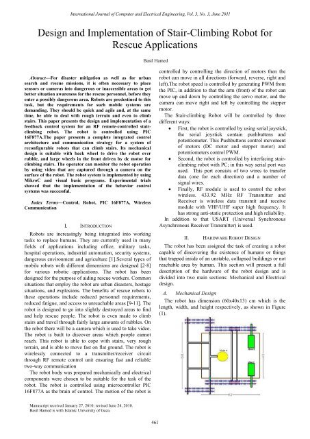
A. Mechanical <strong>Design</strong><br />
The robot has dimension (60x40x13) cm which is the<br />
length, width, <strong>and</strong> height respectively, as shown in Figure<br />
(1).
International Journal <strong>of</strong> Computer <strong>and</strong> Electrical Engineering, Vol. 3, No. 3, June 2011<br />
Figure (1) Top View <strong>of</strong> the <strong>Robot</strong><br />
Gears <strong>and</strong> its Dimension<br />
The robot requires twelve large gears with diameter <strong>of</strong> 17<br />
cm, as shown in Figure (2) eight <strong>of</strong> them joined together <strong>for</strong><br />
robot movement to enable the robot to travel through fairly<br />
large amounts <strong>of</strong> rubble,. The other four large gears join<br />
with four small gears with a diameter <strong>of</strong> 8 cm to be able to<br />
climb the stairs. We use a double bicycle chain to join the<br />
gears.<br />
Figure (2) Gears <strong>of</strong> the <strong>Robot</strong><br />
<strong>Robot</strong> Movement Mechanism:<br />
The robot mechanism drive works with the rear wheels<br />
being directly powered <strong>and</strong> the front wheel system being<br />
driven by the same motor via a series chain. The movement<br />
<strong>of</strong> the robot is established by using two motors in each side.<br />
A servomotor with arm (Satellite Dish Motor) is used to the<br />
case <strong>of</strong> climbing stairs by controlling the position <strong>of</strong> the<br />
motor arm which is joined with the front <strong>of</strong> the robot<br />
Advantages <strong>of</strong> Rear Wheel:<br />
� Maintenance is cheap <strong>and</strong> easy.<br />
� Fixed in long lines <strong>and</strong> roads.<br />
� It's Strong <strong>and</strong> less carrying havoc.<br />
� More com<strong>for</strong>table <strong>and</strong> stable.<br />
� Non-pressure build-up on the front wheels.<br />
� Rear wheel has the task <strong>of</strong> spin, receiving torque<br />
<strong>and</strong> acceleration, which leads to better control <strong>of</strong><br />
the robot.<br />
� The front wheel is responsible <strong>for</strong> the direction<br />
<strong>and</strong> the rear back wheel is <strong>for</strong> push<br />
462<br />
Extra Mechanical Parts<br />
Iron <strong>and</strong> wood are used <strong>for</strong> the body <strong>of</strong> the robot because<br />
they are strong <strong>and</strong> can bear the motor weight <strong>and</strong><br />
movement. The outside cover <strong>of</strong> the robot is fiber plastic<br />
because it is light. Plastic wheels are used to make chain<br />
always in a down the body even when climbs stairs. The<br />
robot is supported by a wireless camera at the top <strong>of</strong> its<br />
surface connected by a stepper motor to control its<br />
movement as shown in Figure (3).<br />
Figure (3) Camera Attached To Stepper Motor<br />
B. Electrical <strong>Design</strong><br />
Block Diagram<br />
The block diagram shown in Figure (4) presents the main<br />
structure <strong>of</strong> the stair-climbing robot which consists <strong>of</strong>:<br />
Power sources, charger circuit, motors (DC motor, Servo<br />
motor, Stepper motor), <strong>and</strong> wireless <strong>and</strong> wire modules. The<br />
brain <strong>of</strong> the robot is PIC16F877A. The following sections<br />
describe in details each <strong>of</strong> these components.<br />
Figure (4) Block Diagram <strong>of</strong> the <strong>Stair</strong>-<strong>Climbing</strong> <strong>Robot</strong><br />
Power Sources<br />
Primary source <strong>of</strong> power <strong>for</strong> the robot are lithium<br />
batteries (Li-ion) because <strong>of</strong> its characteristics <strong>and</strong><br />
advantages. Two batteries (12 Volt 9 Ampere) deliverers,<br />
respectively, to provide 24 volts <strong>and</strong> Can recharge this<br />
batteries using charger circuit.<br />
Power Circuit<br />
Circuit shown in Figure (5) is used to supply the robot<br />
with different values <strong>of</strong> voltages from batteries:<br />
� Directly from batteries 24 volt <strong>for</strong> DC motors <strong>and</strong><br />
Satellite Dish motors.<br />
� Using (LM7812) it generates 12 volt.<br />
� Using (LM7808) it generates 8 volt <strong>for</strong> wireless<br />
camera.<br />
� Using (LM7805) it generates 5 volt <strong>for</strong> control<br />
circuit.<br />
Charger Circuit<br />
The circuitry to recharge the batteries in a portable<br />
product is an important part <strong>of</strong> any power supply design.<br />
The complexity (<strong>and</strong> cost) <strong>of</strong> the charging system is<br />
primarily dependent on the type <strong>of</strong> battery <strong>and</strong> the recharge
time.<br />
International Journal <strong>of</strong> Computer <strong>and</strong> Electrical Engineering, Vol. 3, No. 3, June 2011<br />
Figure (5) Power Circuit<br />
As shown in Figure (6-b)when TR1 is set correctly then<br />
the next round <strong>of</strong> charging it will be notice D1 begin to<br />
flicker as the battery is being charged. When battery is<br />
completely charged, D1 turns ON completely.TR1 do not<br />
need further adjustment anymore. Q1 is connected in line<br />
with the battery <strong>and</strong> is fired by R2, R3<strong>and</strong> D1. The R4, C1,<br />
TR1 <strong>and</strong> D3 sense the voltage <strong>of</strong> the battery terminal <strong>and</strong><br />
activate Q2 when the voltage <strong>of</strong> the battery terminal exceeds<br />
the value predetermined by TR1. When an uncharged<br />
battery is connected, the terminal voltage is low. Under this<br />
circumstance, Q2 is turned OFF <strong>and</strong> Q1 is fired in each half<br />
cycle by R2, R3 <strong>and</strong>D1. The Q1 functions as a simple<br />
rectifier <strong>and</strong> charges the battery. When the battery terminal<br />
voltage is increased the level that had been fixed by TR1will<br />
makes Q2shifts the control <strong>of</strong> Q1 gate. This deactivates Q1<br />
<strong>and</strong> cuts <strong>of</strong>f the current supply to the battery <strong>and</strong> turns D1<br />
ON indicating that the charge has been completed. M1 is a<br />
3ADC ammeter to measure the charge current. The AC/DC<br />
controlled rectifier provides a variable DC load voltage<br />
from a fixed voltage <strong>and</strong> frequency source (220 V ac, 50 Hz)<br />
as shown in Figure (6-a).<br />
Figure (6-a) Full wave Rectifier (AC/DC Converter)<br />
463<br />
III.<br />
Figure (6-b) Charger Circuit<br />
SOFTWARE ROBOT DESIGN<br />
The robot s<strong>of</strong>tware complements the hardware<br />
architecture <strong>of</strong> the stair-climbing robot by providing basic<br />
low-level hardware control that include reading the sensors<br />
value <strong>and</strong> controlling the motor speed.<br />
Mikro C Program: Mikro C is a powerful, feature rich<br />
development tool <strong>for</strong> PIC microcontroller. It is designed to<br />
provide the programmer with the easiest possible solution<br />
<strong>for</strong> developing applications <strong>for</strong> embedded systems, without<br />
compromising per<strong>for</strong>mance or control. [12][13].<br />
Proteus Program: Provides detailed instructions on how<br />
to create new simulator models, using both schematic <strong>and</strong><br />
programmatic (DLL) based techniques. It is an interactive<br />
system level simulator (Figure 19). Which combines mixed<br />
mode circuit simulation, micro-processor models <strong>and</strong><br />
interactive component models to allow the simulation <strong>of</strong><br />
complete micro-controller based designs. [14]<br />
OrCAD PCB Program: used <strong>for</strong> PCB design. An<br />
interactive environment <strong>for</strong> creating <strong>and</strong> editing simple to<br />
complex multi-layer PCBs, it uses powerful shape-based<br />
algorithms <strong>for</strong> speed <strong>and</strong> efficient use <strong>of</strong> the routing area.<br />
OrCAD facilitates rapid design-<strong>and</strong>-simulate cycles,<br />
allowing engineers to explore various design configurations<br />
be<strong>for</strong>e committing to a specific circuit implementation [15].<br />
Visual Basic Program: used <strong>for</strong> Interfacing between PC<br />
<strong>and</strong> the stair-climbing <strong>Robot</strong>. Micros<strong>of</strong>t Visual Basic 6.0 is<br />
used in this paper because <strong>of</strong> its easy programming, easy<br />
displaying <strong>of</strong> visual elements, availability. it is one <strong>of</strong> the<br />
most popular programming languages <strong>and</strong> it is easy to<br />
implement functions using it [16].<br />
PIC16f877A<br />
PIC16f877A is used as the brain <strong>of</strong> the robot that can be<br />
programmed by connecting the serial port <strong>of</strong> the computer<br />
to the PIC microcontroller. The serial port operates at +/-<br />
13V, <strong>and</strong> the PIC serial operates at +5V/0V [17]. MAX232<br />
is used as a level shifter to connect the serial port <strong>of</strong> the<br />
computer to pins RX/TX on PIC as shown in Figure (7).
International Journal <strong>of</strong> Computer <strong>and</strong> Electrical Engineering, Vol. 3, No. 3, June 2011<br />
Figure (7) PIC Interface with Serial Port<br />
DC Motor control<br />
DC Motor shown in Figure (8) is used as the power<br />
engine <strong>of</strong> the stair-climbing robot. The stair-climbing robot<br />
needs high torque with minimum current <strong>for</strong> the robot to be<br />
able to climb stairs. Two types <strong>of</strong> motors are needed: wiper<br />
motors <strong>and</strong> brushless DC motors. That is, minimum current<br />
<strong>and</strong> high speed is supplied from brushless DC motors, <strong>and</strong><br />
high torque is supplied from the gears <strong>of</strong> wiper motors.<br />
Figure (8) DC Motor<br />
Direction <strong>and</strong> Speed Control<br />
H-bridge as shown in Figure (9) is used to control a DC<br />
motor speed <strong>and</strong> direction. It allows the motor to start <strong>and</strong><br />
stop <strong>and</strong> most importantly to reverse direction. In order to<br />
reverse the direction <strong>of</strong> a DC motor, the current through the<br />
DC motor must be reversed.<br />
Figure (9) H-Bridge <strong>Implementation</strong><br />
H-Bridge Operation<br />
� TIP42 (PNP) will be operated when VBE < 0.7.<br />
� TIP41 (NPN) will be operated when VBE≥ 0.7.<br />
� Q5 will be operated when the output <strong>of</strong> (U2A<br />
74L808) is set.<br />
� Q6 will be operated when the output <strong>of</strong> (U2B<br />
74L808) is set.<br />
464<br />
� When Q5 is operated Q1 <strong>and</strong> Q4 will be operated<br />
(rotates left).<br />
� When Q6 is operated Q2 <strong>and</strong> Q3 will be operated<br />
(rotates right).<br />
TABLE (1) OPERATION OF H-BRIDGE<br />
EN DIR Q5 Q6 Q23 Q14 State <strong>of</strong><br />
Motor<br />
0 0 0 0 0 0 Stop<br />
0 1 1 0 0 1 Left<br />
1 0 0 0 0 1 Stop<br />
1 1 0 1 1 0 Right<br />
PWM Generation<br />
To control the speed <strong>of</strong> a D.C. motor a variable voltage<br />
D.C. power source is needed. When a 12V motor switches<br />
on, the motor will start to speed up. Motors do not respond<br />
immediately so it will take a small time to reach full speed.<br />
When power switch <strong>of</strong>f sometime be<strong>for</strong>e the motor reaches<br />
full speed, the motor will start to slow down. When switch<br />
the power on <strong>and</strong> <strong>of</strong>f quickly enough, the motor will run at<br />
some speed part way between zero <strong>and</strong> full speed. This is<br />
exactly what a PWM controller does: it switches the motor<br />
on in a series <strong>of</strong> pulses. To control the motor speed it varies<br />
(modulates) the width <strong>of</strong> the Pulse Width Modulation.<br />
Code<br />
Description<br />
� Pwm_Inti (250) Pwm_Inti (unsigned long<br />
frequency) the value <strong>of</strong> frequency dependent on the<br />
value <strong>of</strong> frequency <strong>of</strong> crystal.<br />
� Pwm_Change_Duty(127) Pwm_Change_Duty<br />
(unsigned short duty_ratio)<br />
� Parameter duty takes values from 0 to 255, where 0<br />
is 0%, 127 is 50%, <strong>and</strong><br />
� 255 is 100% duty ratio. Other specific values <strong>for</strong><br />
duty ratio can be calculated as (Percent*255)/100.<br />
� Pwm_Start() Starts PWM .<br />
Servo Motor Control:<br />
Servo motor is one <strong>of</strong> the DC type motors with feedback<br />
that used in many applications that required controlling the<br />
system in up-down direction. Servos are extremely useful in<br />
robotics [18]. In order to let the robot climb <strong>and</strong> go down<br />
the stairs (up-down direction), servo motor is used. In the<br />
servo motor position control system there is two set points<br />
<strong>and</strong> two sensors (limit switches) used to feedback the<br />
position in<strong>for</strong>mation to the controller.
International Journal <strong>of</strong> Computer <strong>and</strong> Electrical Engineering, Vol. 3, No. 3, June 2011<br />
L298N Dual Full-Bridge Motor Driver<br />
L298 is a dual H-bridge driver as shown in Figure (10)<br />
<strong>for</strong> DC brushed motors <strong>and</strong> stepper motors. It supports a<br />
wide operating voltage range <strong>and</strong> can deliver 2 A per<br />
channel in a through-hole package that is accessible <strong>for</strong> doit-yourself<br />
projects.<br />
L298N Features <strong>and</strong> Specifications<br />
� Operation to 46 V<br />
� Up to 2 A per channel<br />
� Outputs can be paralleled to drive up to 3 A<br />
� Independent ground connections <strong>for</strong> each channel<br />
allow independent current sensing.<br />
� Multiwatt15 through-hole package allows<br />
convenient heat sink mounting <strong>and</strong> easy<br />
prototyping with 0.1" breadboards.<br />
� L298N can control 2 DC Motors, their direction<br />
using control lines <strong>and</strong>0 there. Speed using PWM.<br />
� Dish Satellite motor has a constant speed that is<br />
why it has only direction control.<br />
� The outputs <strong>of</strong> the two motors are connected in<br />
parallel to drive only one .motor to maximize the<br />
output current <strong>of</strong> the bridge (3A).<br />
Figure (10) L298 Dual Full-Bridge Driver<br />
Stepper Motor Control<br />
A stepper Motor is an electromechanical device which<br />
converts electrical pulses into discrete mechanical<br />
movement. The shaft or spindle <strong>of</strong> a stepper motor rotates<br />
indiscrete step increment when electrical comm<strong>and</strong> pulses<br />
are applied to it in the proper sequence. The sequence <strong>of</strong> the<br />
applied pulses is directly related to the direction <strong>of</strong> the<br />
motor shaft rotation [19]. The main advantage <strong>of</strong> stepper<br />
motors is that they can achieve accurate position control<br />
without the requirement <strong>for</strong> position feedback. Stepper<br />
motor is used <strong>for</strong> the rotation <strong>of</strong> the camera in both Left <strong>and</strong><br />
Right directions.<br />
Uln2003 - Seven Darlington Arrays<br />
ULN2003 is High Voltage / High Current Darlington<br />
Transistor Arrays; it's monolithic high voltage <strong>and</strong> high<br />
current Darlington transistor arrays. It consists <strong>of</strong> seven<br />
NPN Darlington pairs that feature high-voltage outputs<br />
(50V) with common cathode clamp diode <strong>for</strong> switching<br />
inductive loads. The collector-current rating <strong>of</strong> single<br />
Darlington pair is 500mA. The Darlington pairs may be<br />
paralleled <strong>for</strong> higher current capability. Applications include<br />
relay drivers, hammer drivers, lamp drivers, display drivers<br />
(LED gas discharge), line drivers, <strong>and</strong> logic buffers [20]. Its<br />
inputs pinned opposite outputs to simplify layout. This is<br />
more adequate to control a four phase unipolar stepper<br />
motor.<br />
465<br />
Code<br />
Figure (11) Stepper Circuit<br />
Description<br />
i=0 is an initial value, which will be incremented<br />
gradually from the statement i++; this causes the sequence<br />
to be {case 1, case2, case3, case4} <strong>and</strong> the motor to rotate<br />
Left.<br />
Serial Joystick<br />
The movement <strong>of</strong> the stick <strong>of</strong> the joystick presents<br />
varying <strong>of</strong> the value <strong>of</strong> the potentiometer in either sides X or<br />
Y , As shown Figure (12) where the maximum value in the<br />
most <strong>for</strong>ward or most right is 4.8 V , <strong>and</strong> the minimum<br />
value is 0 V ,otherwise at its home position it has a value <strong>of</strong><br />
2.5 V . On the other h<strong>and</strong> the pushbuttons give on/<strong>of</strong>f<br />
voltage values 0 or 5 V. These Push buttons control the<br />
movement <strong>of</strong> motors (servo motor <strong>and</strong> stepper motor) <strong>and</strong><br />
potentiometers control the speed <strong>of</strong> DC motors.<br />
Figure (12) Joystick Connection<br />
Interface between stair-climbing robot <strong>and</strong> PC<br />
Personal computers (PC) have a large number <strong>of</strong> ports<br />
that you could add your own hardware to control stairclimbing<br />
robot. Some <strong>of</strong> these are very easy to use, while<br />
others are nearly impossible without special (expensive) ICs.<br />
Not all <strong>of</strong> these interfaces are available on all computers.
International Journal <strong>of</strong> Computer <strong>and</strong> Electrical Engineering, Vol. 3, No. 3, June 2011<br />
Serial Port<br />
The serial port as shown in Figure (13) is one <strong>of</strong> the two<br />
easiest to use ports on a PC. This port consists <strong>of</strong> 2 wires to<br />
transfer data (one <strong>for</strong> each direction) <strong>and</strong> a number <strong>of</strong> signal<br />
wires. This port is reasonably sturdy, <strong>and</strong> knowing digital<br />
electronics <strong>and</strong> how to use a microcontroller, is pretty easy<br />
to use. It is limited on speed <strong>and</strong> can only connect two<br />
devices directly.<br />
Figure (13) RS-232 Serial Communication<br />
USART<br />
USART st<strong>and</strong>s <strong>for</strong> Universal Synchronous Asynchronous<br />
Receiver Transmitter. It is sometimes called the Serial<br />
Communications Interface or SCI. Synchronous operation<br />
uses a clock <strong>and</strong> data line while there is no separate clock<br />
accompanying the data <strong>for</strong> Asynchronous transmission.<br />
Since there is no clock signal in asynchronous operation,<br />
one pin can be used <strong>for</strong> transmission <strong>and</strong> another pin can be<br />
used <strong>for</strong> reception. Both transmission <strong>and</strong> reception can<br />
occur at the same time - this is known as full duplex<br />
operation. Transmission <strong>and</strong> reception can be independently<br />
enabled. However, when the serial port is enabled, the<br />
USART will control both pins <strong>and</strong> one cannot be used <strong>for</strong><br />
general-purpose I/O when the other is being used <strong>for</strong><br />
transmission or reception. The most common use <strong>of</strong> the<br />
USART in asynchronous mode is to communicate to a PC<br />
serial port using the RS-232 protocol. A driver is required to<br />
interface to RS-232 voltage levels <strong>and</strong> the PIC; MCU<br />
should not be directly connected to RS-232 signals [21].<br />
MAX232 is used as a driver (voltage level shifter) as<br />
explained earlier.<br />
USART Library:<br />
USART hardware module is available with<br />
PIC16F877A .This library is used to communicate between<br />
PC <strong>and</strong> PIC16F877A, thus we enabled to control the robot<br />
via mouse or USB joystick<br />
Code<br />
Description<br />
� USART_InitInitializeshardware USART module<br />
with the desired baud rate.<br />
� UsartData_Ready () USART_ReadIf data is<br />
ready, read it.<br />
Then the received data will be examined <strong>and</strong> the proper<br />
function will be executed.<br />
Visual basic Programming<br />
The design <strong>of</strong> any successful robot involves interface<br />
s<strong>of</strong>tware with PC. Visual Basic program is one <strong>of</strong> the best to<br />
466<br />
implement this function. Connection to the RS-232 port is<br />
accomplished with the Visual Basic st<strong>and</strong>ard MSCOMM<br />
control. By using these features <strong>of</strong> Visual Basic the code is<br />
completely transportable. Through a series <strong>of</strong> buttons <strong>and</strong><br />
comm<strong>and</strong>s on the interface s<strong>of</strong>tware we can control all<br />
movements <strong>of</strong> the robot as shown in Figure (14). It consists<br />
<strong>of</strong> frame Movement <strong>of</strong> robot control direction <strong>of</strong> two DC<br />
motors <strong>for</strong>ward or reverse, left or right, as well as control<br />
servomotor. Frame Direction <strong>of</strong> Camera to control Stepper<br />
motor that move camera left or right <strong>and</strong> frame audio video<br />
control (A/V Control) used to control the function <strong>of</strong> camera<br />
as shown in Figure (15) .<br />
Code<br />
Figure (14) Serial Connection between PC <strong>and</strong> <strong>Stair</strong>-<strong>Climbing</strong> <strong>Robot</strong><br />
Description<br />
� Initializing <strong>and</strong> Opening the Com port, Create an<br />
instance <strong>of</strong> CRs232 then set0COM parameters<br />
be<strong>for</strong>e invoking the Open method.<br />
� Transmitting data to COM Port: when continue<br />
pressing on the comm<strong>and</strong> sends serially signal.<br />
� Joystick.ocx to read from USB joystick.<br />
� Resize.ocx to zoom out interface s<strong>of</strong>tware.<br />
� ezVidCap.ocx to control functions <strong>of</strong> camera.<br />
Figure (15) Video Captured Using Wireless Camera
International Journal <strong>of</strong> Computer <strong>and</strong> Electrical Engineering, Vol. 3, No. 3, June 2011<br />
IV. WIRELESS COMMUNICATION<br />
Wireless communication involves the electromagnetic<br />
spectrum, which has many unique qualities. Radio waves<br />
propagate according to the spectrum’s wavelength.<br />
Antennas provide an impedance match to the airwaves. The<br />
RF Module provides a convenient interface <strong>for</strong> wireless it's<br />
allow engineers <strong>of</strong> all skill levels to quickly <strong>and</strong> costeffectively<br />
add wireless capabilities to virtually any product.<br />
It consists <strong>of</strong> two IC's TX <strong>and</strong> RX. It can be installed in a<br />
suitable location up to 100 meters cabling distance from the<br />
Control Module. This allows a greater degree <strong>of</strong> flexibility<br />
<strong>for</strong> optimizing the location <strong>of</strong> the RF receiver <strong>for</strong> the best<br />
coverage. The robot remote control in this project in one<br />
direction to send a signal from the PC <strong>and</strong> received by the<br />
PIC on the body <strong>of</strong> the robot as shown in Figure (16).<br />
Figure (16) Wireless Communication between PC <strong>and</strong> <strong>Stair</strong>-<strong>Climbing</strong><br />
<strong>Robot</strong><br />
Connection <strong>of</strong> RF Module in <strong>Stair</strong>-<strong>Climbing</strong> <strong>Robot</strong><br />
In <strong>Stair</strong>-<strong>Climbing</strong> <strong>Robot</strong> TX is located near the computer<br />
connected to it by a cable from the computer to max circuit<br />
where the TX locate, RX is located on the surface <strong>of</strong> the<br />
<strong>Stair</strong>-<strong>Climbing</strong> robot as shown in Figure (17), in order to<br />
control the movement <strong>of</strong> the robot from the wave transmit<br />
from the computer throw TX to the robot throw RX.<br />
Figure (17) Connection <strong>of</strong> RF Module in <strong>Stair</strong>-<strong>Climbing</strong> <strong>Robot</strong><br />
As explained previously the stair-climbing robot can be<br />
controlled wired through the joystick or via a serial port<br />
between the PC <strong>and</strong> PIC as shown in Figure (7) or wireless<br />
via RF module that connect directly with PIC without<br />
MAX232 as shown in Figure (18). This adjustment<br />
manually on the PIC circuit by connectors<br />
Figure (18) Wireless Connection<br />
V. CONCLUSIONS<br />
The robot is called stair-climbing robot from the fact that<br />
it's designed to cope with stairs, very rough terrain, <strong>and</strong> is<br />
able to move fast on flat ground. To sum up, the main<br />
467<br />
concern <strong>of</strong> this paper is to design a rescue robot that is<br />
capable to go into slightly destroyed areas to find <strong>and</strong> help<br />
rescue people.PIC16F877 is used in this robot in order to<br />
control the direction (right, left, <strong>for</strong>ward <strong>and</strong> reverse) using<br />
two DC motors in both sides <strong>of</strong> the robot using H-bridge as<br />
driver. Also PIC is used to control the motion <strong>of</strong> camera<br />
using stepper motor <strong>and</strong> the motion <strong>of</strong> servo motor which is<br />
used to let the robot climb <strong>and</strong> go down the stairs. PIC is the<br />
brain <strong>of</strong> stair-climbing robot. The overall system worked<br />
successfully. Firstly we tested our robot using serial joystick<br />
(wired system).Then RF module (transmitter <strong>and</strong> receiver)<br />
is used in order to make the system wireless by using USB<br />
joystick control. The control used was by making interface<br />
between PIC <strong>and</strong> visual basic in both directions; sending<br />
data from computer to robot or vice versa. Overall benefits<br />
<strong>of</strong> rescue robots to these operations include reduced<br />
personnel requirements, reduced fatigue, <strong>and</strong> access to<br />
unreachable areas<br />
Figure (19) <strong>Stair</strong>-<strong>Climbing</strong> <strong>Robot</strong> Proteus Simulation<br />
Figure (20) <strong>Stair</strong>-<strong>Climbing</strong> <strong>Robot</strong><br />
REFERENCES<br />
[1] R. C. Luo , K. L. Su, “Amultiagentmulti sensor based real-time<br />
sensory control system <strong>for</strong> intelligent security robot” IEEE<br />
International Conference on <strong>Robot</strong>ics <strong>and</strong> Automation, vol. 2, 2003,<br />
pp.2394 –2399.<br />
[2] G. T. Sibley, M. H. Rahimi, G. S. Sukhatme, “Robomote: a tiny<br />
mobile robot plat<strong>for</strong>m <strong>for</strong> large-scale ad-hoc sensor networks”, IEEE<br />
International Conference on <strong>Robot</strong>ics <strong>and</strong> Automation, ICRA '02,<br />
vol.2,2002, pp.1143-1148.<br />
[3] S. Bergbreiter, K. S. J. Pister, “Cots Bots: an <strong>of</strong>f-the-shelf plat<strong>for</strong>m<br />
<strong>for</strong> distributed robotics”, IEEE/RSJ International Conference on<br />
Intelligent <strong>Robot</strong>s <strong>and</strong> Systems, IROS’03, vol.2, 2003, pp.1632-1637.
International Journal <strong>of</strong> Computer <strong>and</strong> Electrical Engineering, Vol. 3, No. 3, June 2011<br />
[4] A. Arora, E. Ertin, R. Ramnath, M. Nesterenko, W. Leal, “Kansei:<br />
high-fidelity sensing tested”, IEEE Internet Computing, vol.10,<br />
2006,pp. 35- 47.<br />
[5] H. Utz, S. Sablatnog, S. Enderle, G. Kraetzschmar, “Miro–<br />
middleware<strong>for</strong> mobile robot applications”, IEEE Transactions on<br />
<strong>Robot</strong>ics <strong>and</strong> Automation, vol.18, 2002, pp. 493- 497.<br />
[6] G. Caprari, K. O. Arras, R. Siegwart, “The autonomous miniature<br />
robot Alice: from prototypes to applications”, IEEE/RSJ International<br />
Conference on Intelligent <strong>Robot</strong>s <strong>and</strong> Systems, IROS 2000, vol.1,<br />
2000, pp. 793-798.<br />
[7] G. Metta, P. Fitzpatrick, L. Natale,YARP: “Yet another <strong>Robot</strong><br />
Plat<strong>for</strong>m”, International Journal <strong>of</strong> Advanced <strong>Robot</strong>ic Systems, vol. 3,<br />
2006, pp.43-48.<br />
[8] Kalantari, A. Mihankhah, E. Moosavian, S.A.A. “Safe autonomous<br />
stair climbing <strong>for</strong> a tracked mobile robot using a kinematics based<br />
controller” AIM. IEEE/ASME International Conference on Advanced<br />
Intelligent Mechatronics, 2009.<br />
[9] Akhtaruzzaman, M.; IzzatiBt Samsuddin, N.; Bt Umar, N.; Rahman,<br />
M.;” <strong>Design</strong> <strong>and</strong> development <strong>of</strong> a wall climbing <strong>Robot</strong> <strong>and</strong> its<br />
control system” 12th International Conference on Computers <strong>and</strong><br />
In<strong>for</strong>mation Technology, 2009. ICCIT '09.<br />
[10] Sung Kyun Lim Dong Il Park Yoon Keun Kwak Byung-Soo Kim<br />
Sang-Won Jeon, “ Variable geometry single-tracked mechanism <strong>for</strong> a<br />
rescue robot” , Workshop, 2005 IEEE International Safety, Security<br />
<strong>and</strong> Rescue <strong>Robot</strong>ics.<br />
[11] Gaston, J. Raahemifar, K. Hiscocks, P “ A cooperative network <strong>of</strong><br />
reconfigurable stair-climbing robots”, ISCAS 2006. Proceedings.<br />
IEEE International Symposium on Circuits <strong>and</strong> Systems, 2006.<br />
[12] PIC Microcontrollers 1st EDITION (2008) Milan Verle,<br />
mikroElektronika<br />
[13] Muhammad Ali Mazidi, Rolin D. Mackinaly, Danny Causey, “PIC<br />
MICROCONTROLLER AND EMBEDDED SYSTEMS Using<br />
Assembly <strong>and</strong> C <strong>for</strong> PIC18,” New Jersey, Prentice Hall, 2006.<br />
468<br />
[14] Proteus Pr<strong>of</strong>essional PCB <strong>Design</strong> <strong>and</strong> Simulation<br />
www.labcenter.co.uk/<br />
[15] http://www.cadence.com/products/orcad/orcad_pcb_designer/pages/d<br />
efault.aspx<br />
[16] Osama El Huseni, “Visual Basic <strong>for</strong> Windows,” IbnSina Library,<br />
1994.<br />
[17] PIC16F87XA Datasheet, Pin Enhanced Flash Microcontrollers,<br />
Microchip Technology Inc., 2003.<br />
[18] Riazollah Firoozian,” Servo Motors <strong>and</strong> Industrial Control Theory”<br />
Springer; 1st edition (December 8, 2008)<br />
[19] Kenjo, Takashi,“Stepping motors <strong>and</strong> their microprocessor controls”<br />
Ox<strong>for</strong>d University Press, c1984.<br />
[20] http://www.datasheetdir.com/ULN2003+Darlin gton-Transistor-<br />
Arrays<br />
[21] http://www.alldatasheet.com/datasheetpdf/pdf25575/STMICROELE<br />
CTRONICS/ULN2003.html<br />
Dr. Basil Hamed is Assistant Pr<strong>of</strong>essor <strong>of</strong> Electrical Engineering<br />
Department, Islamic University <strong>of</strong> Gaza, Palestine, since 1999. He has<br />
Bachelor Degree in Electrical Engineering from New Mexico State<br />
University, NM. USA in the year <strong>of</strong> 1989, he received Master degree from<br />
University <strong>of</strong> New Orleans, La. USA in the year <strong>of</strong> 1992, <strong>and</strong> earned his<br />
PhD from New Mexico State University, NM USA in the year 1999. He<br />
has 15 years <strong>of</strong> teaching experience <strong>and</strong> has published many papers in<br />
national <strong>and</strong> international journals. His fields <strong>of</strong> interest include Control<br />
Systems, Fuzzy Control, Simulation & Modeling, <strong>Robot</strong>ics, FPGA, Signal<br />
<strong>and</strong> Image Processing.