Design and Implementation of Stair-Climbing Robot for ... - ijcee
Design and Implementation of Stair-Climbing Robot for ... - ijcee
Design and Implementation of Stair-Climbing Robot for ... - ijcee

Create successful ePaper yourself
Turn your PDF publications into a flip-book with our unique Google optimized e-Paper software.
International Journal <strong>of</strong> Computer <strong>and</strong> Electrical Engineering, Vol. 3, No. 3, June 2011<br />
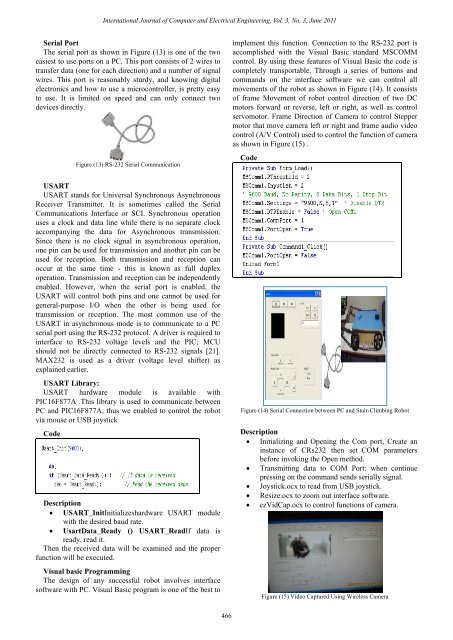
Serial Port<br />
The serial port as shown in Figure (13) is one <strong>of</strong> the two<br />
easiest to use ports on a PC. This port consists <strong>of</strong> 2 wires to<br />
transfer data (one <strong>for</strong> each direction) <strong>and</strong> a number <strong>of</strong> signal<br />
wires. This port is reasonably sturdy, <strong>and</strong> knowing digital<br />
electronics <strong>and</strong> how to use a microcontroller, is pretty easy<br />
to use. It is limited on speed <strong>and</strong> can only connect two<br />
devices directly.<br />
Figure (13) RS-232 Serial Communication<br />
USART<br />
USART st<strong>and</strong>s <strong>for</strong> Universal Synchronous Asynchronous<br />
Receiver Transmitter. It is sometimes called the Serial<br />
Communications Interface or SCI. Synchronous operation<br />
uses a clock <strong>and</strong> data line while there is no separate clock<br />
accompanying the data <strong>for</strong> Asynchronous transmission.<br />
Since there is no clock signal in asynchronous operation,<br />
one pin can be used <strong>for</strong> transmission <strong>and</strong> another pin can be<br />
used <strong>for</strong> reception. Both transmission <strong>and</strong> reception can<br />
occur at the same time - this is known as full duplex<br />
operation. Transmission <strong>and</strong> reception can be independently<br />
enabled. However, when the serial port is enabled, the<br />
USART will control both pins <strong>and</strong> one cannot be used <strong>for</strong><br />
general-purpose I/O when the other is being used <strong>for</strong><br />
transmission or reception. The most common use <strong>of</strong> the<br />
USART in asynchronous mode is to communicate to a PC<br />
serial port using the RS-232 protocol. A driver is required to<br />
interface to RS-232 voltage levels <strong>and</strong> the PIC; MCU<br />
should not be directly connected to RS-232 signals [21].<br />
MAX232 is used as a driver (voltage level shifter) as<br />
explained earlier.<br />
USART Library:<br />
USART hardware module is available with<br />
PIC16F877A .This library is used to communicate between<br />
PC <strong>and</strong> PIC16F877A, thus we enabled to control the robot<br />
via mouse or USB joystick<br />
Code<br />
Description<br />
� USART_InitInitializeshardware USART module<br />
with the desired baud rate.<br />
� UsartData_Ready () USART_ReadIf data is<br />
ready, read it.<br />
Then the received data will be examined <strong>and</strong> the proper<br />
function will be executed.<br />
Visual basic Programming<br />
The design <strong>of</strong> any successful robot involves interface<br />
s<strong>of</strong>tware with PC. Visual Basic program is one <strong>of</strong> the best to<br />
466<br />
implement this function. Connection to the RS-232 port is<br />
accomplished with the Visual Basic st<strong>and</strong>ard MSCOMM<br />
control. By using these features <strong>of</strong> Visual Basic the code is<br />
completely transportable. Through a series <strong>of</strong> buttons <strong>and</strong><br />
comm<strong>and</strong>s on the interface s<strong>of</strong>tware we can control all<br />
movements <strong>of</strong> the robot as shown in Figure (14). It consists<br />
<strong>of</strong> frame Movement <strong>of</strong> robot control direction <strong>of</strong> two DC<br />
motors <strong>for</strong>ward or reverse, left or right, as well as control<br />
servomotor. Frame Direction <strong>of</strong> Camera to control Stepper<br />
motor that move camera left or right <strong>and</strong> frame audio video<br />
control (A/V Control) used to control the function <strong>of</strong> camera<br />
as shown in Figure (15) .<br />
Code<br />
Figure (14) Serial Connection between PC <strong>and</strong> <strong>Stair</strong>-<strong>Climbing</strong> <strong>Robot</strong><br />
Description<br />
� Initializing <strong>and</strong> Opening the Com port, Create an<br />
instance <strong>of</strong> CRs232 then set0COM parameters<br />
be<strong>for</strong>e invoking the Open method.<br />
� Transmitting data to COM Port: when continue<br />
pressing on the comm<strong>and</strong> sends serially signal.<br />
� Joystick.ocx to read from USB joystick.<br />
� Resize.ocx to zoom out interface s<strong>of</strong>tware.<br />
� ezVidCap.ocx to control functions <strong>of</strong> camera.<br />
Figure (15) Video Captured Using Wireless Camera