Modeling and Calibration of a Structured-light Optical - Michigan ...
Modeling and Calibration of a Structured-light Optical - Michigan ...
Modeling and Calibration of a Structured-light Optical - Michigan ...

You also want an ePaper? Increase the reach of your titles
YUMPU automatically turns print PDFs into web optimized ePapers that Google loves.
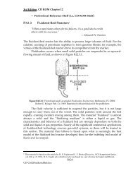
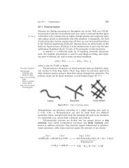
Fig. 1 Integration <strong>of</strong> a laser stripe sensor to a CMM<br />
The multiple-axis integrated system allows the sensor to be<br />
rotated to any angle for optimal view <strong>of</strong> the part surface to be<br />
measured. The same sensor can also be attached to the endeffector<br />
<strong>of</strong> a robot. The robot itself cannot be used for scanning<br />
due to its poor positioning accuracy. However, when combined<br />
with a precision X-Y motion stage, the robot integrated system<br />
has its advantages: the robot arm can easily position the sensor<br />
to reach <strong>and</strong> measure large parts from many positions <strong>and</strong> orientations.<br />
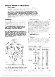
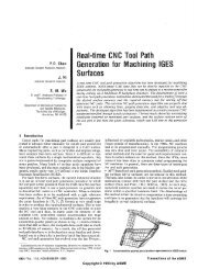
Since the laser scanner is only a two dimensional sensor, a<br />
third dimension needs to be integrated to the system to realize<br />
3-D measurements. When scanning a part, the CMM shaft<br />
moves the sensor along a certain axis, e.g., the X axis, in small<br />
increments at a fixed speed. The sensor provides Ys <strong>and</strong> Zs data<br />
while the optical (or magnetic) scale <strong>of</strong> the CMM X axis provides<br />
the Xs information (Fig. 2). If the part instead <strong>of</strong> the<br />
sensor moves, the scanning mechanism is the same.<br />
If the laser plane, on which the sensor coordinate frame Ys-<br />
Zs lies, is always perpendicular to the surface to be measured<br />
(i.e., the laser plane is placed perpendicular to the CMM Xaxis),<br />
the coordinate system thus formed is Cartesian. However,<br />
this severely limits the application <strong>of</strong> the system, practically<br />
precluding the measurement <strong>of</strong> complex parts requiring multiple-axis<br />
scanner motions <strong>and</strong> multiple orientations <strong>of</strong> the laser<br />
sensor to achieve an optimal projecting angle.<br />
During scanning, the laser scanning coordinate system usually<br />
is non-orthogonal, i.e., skewed. If data obtained from this<br />
mechanical driving<br />
direction(Xs)<br />
<strong>Structured</strong> laser<br />
line <strong>light</strong>ing<br />
/ Sensing optics<br />
>• Xs: added axis<br />
Fig. 2 2D sensor used for 3D measurement<br />
596 / Vol. 118, NOVEMBER 1996<br />
imaginary Cartesian sensor Zs(Zs')<br />
coordinate system {S'}<br />
world coordinate system {W}<br />
Xw<br />
YsCYs 1 )<br />
real skewed sensor<br />
coordinate system (S}<br />
Fig. 3 Characterization <strong>of</strong> the laser stripe scanning system<br />
skewed coordinate system are to be used for dimensional measurement,<br />
they have to be transformed to a Cartesian frame.<br />
Otherwise, the dimensions on the part will be distorted, e.g.,<br />
after non-Cartesian scanning, a sphere in real space will look<br />
like an ellipsoid <strong>and</strong> a cube will look like an inclined parallelepiped.<br />
3 System <strong>Modeling</strong><br />
3.1 Skewed Frame Representation. Three frames, the<br />
world coordinate frame {W}, an imaginary sensor coordinate<br />
system {S'} <strong>and</strong> the sensor's body frame {S}, as shown in<br />
Figs. 3 <strong>and</strong> 4, are used in the following discussions. Both {W}<br />
<strong>and</strong> {S'} are Cartesian frames, but {S} frame is not. {S} <strong>and</strong><br />
{S'} frames share the same origin. Let b aTbe the 4 X 4 matrix<br />
representation <strong>of</strong> coordinate transformation from {a} to {b},<br />
a, b e {W,S',S). Then<br />
T is a homogeneous transform <strong>of</strong> which various equivalent<br />
representations exist (e.g., Craig, 1992; Wang, 1992). This paper<br />
adopts the matrix representation using the roll-pitch-yaw<br />
angles (a, /3, y):<br />
"T =<br />
cacfi<br />
sac (3<br />
-sp<br />
0<br />
cas0sy — sacy<br />
sasfisy + cacy<br />
cfisy<br />
0<br />
caspcy + sasy<br />
sas/3cy — easy<br />
c0cy<br />
0<br />
: where sin a sa, cos a •• = COL <strong>and</strong> (qx,qy,qz, 1 )<br />
vector Neither fT nor<br />
form. Their representations are explored below<br />
T is a translation<br />
W<br />
T constitutes a homogeneous trans-<br />
Ys(Ys<br />
A x^<br />
Fig. 4 Spatial relationship between the real skewed sensor coordinate<br />
system {S} <strong>and</strong> the imaginary Cartesian coordinate system {S }<br />
(1)<br />
(2)<br />
Transactions <strong>of</strong> the ASME<br />
Downloaded 26 Sep 2011 to 141.212.97.74. Redistribution subject to ASME license or copyright; see http://www.asme.org/terms/Terms_Use.cfm