Real-time CNC Tool Path Generation for Machining IGES Surfaces
Real-time CNC Tool Path Generation for Machining IGES Surfaces
Real-time CNC Tool Path Generation for Machining IGES Surfaces

Create successful ePaper yourself
Turn your PDF publications into a flip-book with our unique Google optimized e-Paper software.
Y.D. Chen<br />
Graduate Student Research Assistant.<br />
J. Ni<br />
Assistant Research Scientist.<br />
S. M. Wu<br />
R. and P. Anderson Professor of<br />
Manufacturing Technology.<br />
Department of Mechanical Engineering<br />
and Applied Mechanics,<br />
The University of Michigan,<br />
Ann Arbor, Ml 48109<br />
1 Introduction<br />
Cutter paths <strong>for</strong> machining part surfaces are usually generated<br />
in advance either manually <strong>for</strong> simple part geometries<br />
or automatically after a part is designed in a CAD station.<br />
Many engineering parts, such as car bodies and airplane wings,<br />
have complex free-<strong>for</strong>m surfaces. Since it is difficult to represent<br />
these surfaces by a single mathematical equation, they<br />
are in general represented by composite surfaces composed of<br />
many patches. Many kinds of surface patch equations have<br />
been developed, and the most popular one is the bicubic parametric<br />
patch: entity type 114 defined in the Initial Graphics<br />
Exchange Specification (<strong>IGES</strong>).<br />
For such free-<strong>for</strong>m surfaces, the current industrial practice<br />
is to use an off-line tool path generation procedure by which<br />
the tool path is first generated from the CAD data files (surface<br />
equations) and then to use a post-processor to generate and<br />
to download NC codes to a <strong>CNC</strong> controller. When a complex<br />
free-<strong>for</strong>m surface is to be machined with a tight tolerance<br />
requirement, the off-line NC path generators have to generate<br />
the cutter locations in {X, Y, Z) <strong>for</strong>mat at very small steps<br />
in order to produce the required smooth surfaces. This in turn<br />
requires a very large memory in the <strong>CNC</strong> controller to store<br />
the NC tool path data. In many cases the memory of the<br />
available <strong>CNC</strong> controllers cannot accommodate this huge<br />
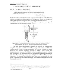
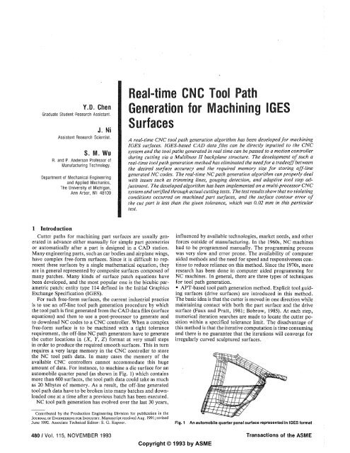
amount of data. For instance, to machine a die surface <strong>for</strong> an<br />
automobile quarter panel (as shown in Fig. 1) which contains<br />
more than 600 surfaces, the tool path data could take as much<br />
as 20 Mbytes of memory. As a result, the off-line generated<br />
tool path data have to be broken into many batches and downloaded<br />
one at a <strong>time</strong> after a previous batch has been executed.<br />
NC tool path generation has evolved over the last 30 years,<br />
<strong>Real</strong>-<strong>time</strong> <strong>CNC</strong> <strong>Tool</strong> <strong>Path</strong><br />
<strong>Generation</strong> <strong>for</strong> <strong>Machining</strong> <strong>IGES</strong><br />
<strong>Surfaces</strong><br />
A real-<strong>time</strong> <strong>CNC</strong> tool path generation algorithm has been developed <strong>for</strong> machining<br />
<strong>IGES</strong> surfaces. <strong>IGES</strong>-based CAD data files can be directly inputted to the <strong>CNC</strong><br />
system and the tool paths generated in real <strong>time</strong> can be passed to a motion controller<br />
during cutting via a Multibuss II backplane structure. The development of such a<br />
real-<strong>time</strong> tool path generation method has eliminated the need <strong>for</strong> a tradeoff between<br />
the desired surface accuracy and the required memory size <strong>for</strong> storing off-line<br />
generated NC codes. The real-<strong>time</strong> NC path generation algorithm can properly deal<br />
with issues such as trimming lines, gouging detection, and adaptive tool step adjustment.<br />
The developed algorithm has been implemented on a multi-processor <strong>CNC</strong><br />
system and verified through actual cutting tests. The test results show that no violating<br />
conditions occurred on machined part surfaces, and the surface contour error of<br />
the cut part is less than the given tolerance, which was 0.02 mm in this particular<br />
test.<br />
influenced by available technologies, market needs, and other<br />
<strong>for</strong>ces outside of manufacturing. In the 1960s, NC machines<br />
had to be programmed manually. The programming process<br />
was very slow and error prone. The availability of computer<br />
aided methods and the need <strong>for</strong> speed and responsiveness continue<br />
to reduce reliance on this method. Since the 1970s, more<br />
research has been done in computer aided programming <strong>for</strong><br />
NC machines. In general, there are three types of techniques<br />
<strong>for</strong> tool path generation.<br />
• APT-based tool path generation method. Explicit tool guiding<br />
surfaces (drive surfaces) are introduced in this method.<br />
The basic idea is that the cutter is moved in one direction while<br />
maintaining contact with both the part surface and the drive<br />
surface (Faux and Pratt, 1981; Bobrow, 1985). At each step,<br />
numerical iteration searches are made to locate the cutter position<br />
within a specified tolerance limit. The disadvantage of<br />
this method is that the iterative computation is <strong>time</strong> consuming<br />
and there is no guarantee that the iterations will converge <strong>for</strong><br />
irregularly curved sculptured surfaces.<br />
Contributed by the Production Engineering Division <strong>for</strong> publication in the<br />
JOURNAL OF ENGINEERING FOR INDUSTRY. Manuscript received Aug. 1991; revised<br />
June 1992. Associate Technical Editor: S. G. Kapoor. Fig. 1 An automobile quarter panel surface represented in <strong>IGES</strong> <strong>for</strong>mat<br />
480 / Vol. 115, NOVEMBER 1993 Transactions of the ASME<br />
Copyright © 1993 by ASME
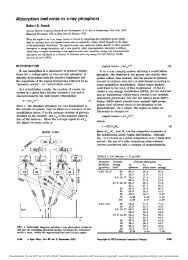
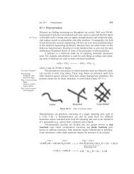
Fig. 2 Parametric Spline Surface (<strong>IGES</strong> Type 114)<br />
• Cartesian machining method. <strong>Tool</strong> paths are planned on the<br />
XY-plane of a Cartesian coordinate system. The cutter path<br />
is the intersection of the part surface and a vertical plane<br />
perpendicular to the XY-plane (Choi et al., 1988, 1989; Bobrow,<br />
1985). In this method, the cutter plane has to be a vertical<br />
plane. Because gouging points may not be on the vertical cutter<br />
plane, the search <strong>for</strong> gouging points must be per<strong>for</strong>med on<br />
the entire part surface.<br />
• Parametric machining method. <strong>Tool</strong> paths are planned on<br />
the parametric space. There are two ways to calculate the tool<br />
paths. (/) The tool is moved at equally spaced points on the<br />
w-line or y-line of the surface. Corresponding to each selected<br />
point on the u-v domain, a (x, y, z) point on the part surface<br />
can be calculated and used as tool paths. The drawback of<br />
this scheme is the difficulty of controlling the tolerance on a<br />
part surface based only on the u-v domain point interval. The<br />
equally spaced points in the parameter space may result in<br />
differently spaced points on the part surface (Bobrow, 1985).<br />
(2) The points and normal vectors on a part surface are first<br />
evaluated at predefined small intervals of both parameters u<br />
and v. The tool path is then generated by searching through<br />
this huge data array of part surface points in a given cutter<br />
plane. This method is widely used in commercial NC software.<br />
The operations of filters are per<strong>for</strong>med in order to generate<br />
the smallest tool path point and reduce the tool path data size.<br />
The filler operations are also necessary to insert points in the<br />
interval if it is not small enough. The operations of filler and<br />
filter are very <strong>time</strong> consuming.<br />
All these off-line tool path generation methods have a common<br />
drawback. There is always a tradeoff between the level<br />
of path precision, in terms of the coarseness of tool path points<br />
on a sculptured surface, and the memory requirement.<br />
This paper presents a new method <strong>for</strong> the real-<strong>time</strong> generation<br />
of NC tool paths to produce free-<strong>for</strong>m sculptured surfaces<br />
on a 3-axis milling machine. This method is intended to<br />
eliminate the need <strong>for</strong> the tradeoff between path precision and<br />
memory requirement. The unique feature of this real-<strong>time</strong> path<br />
generation method is that it can generate as many points as<br />
needed within each computational cycle <strong>time</strong>. The method is<br />
designed to generate NC tool paths directly from <strong>IGES</strong> 114<br />
data files since the <strong>IGES</strong> is the main standard electronic data<br />
translator recognized by the ANSI.<br />
A new <strong>CNC</strong> controller is being developed based on the<br />
Multibus II structure and the iRMX-III operating system. The<br />
controller is a true multi-processor and multi-tasking system.<br />
One of the processors in this controller is used as a Free-Form<br />
Surface Milling <strong>Tool</strong> <strong>Path</strong> Processor, which can read <strong>IGES</strong><br />
data directly from a CAD data file and generate the <strong>CNC</strong> tool<br />
path during machining operations. The tool path data is then<br />
passed to motion controller processors through the Multibus<br />
in real <strong>time</strong>.<br />
The definitions of <strong>IGES</strong> surfaces and the derivation of their<br />
offset surfaces are given in Section 2. The proposed tool path<br />
generation algorithms <strong>for</strong> free-<strong>for</strong>m sculptured surfaces are<br />
presented in Section 3. The issues of tool path planning, tool<br />
step calculation, gouging detection, tool path interval, and<br />
trimmed surfaces are discussed in detail. These developed algorithms<br />
are verified through actual cutting tests, and the<br />
results are presented in Section 4.<br />
Journal of Engineering <strong>for</strong> Industry<br />
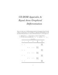
Fig. 3 <strong>Tool</strong> position definitions<br />
2 <strong>IGES</strong> <strong>Surfaces</strong> and Their Offset <strong>Surfaces</strong><br />
<strong>IGES</strong> is a widely used CAD data file structure. All major<br />
CAD software packages support the <strong>IGES</strong> input and output<br />
<strong>for</strong>mat. The <strong>IGES</strong> data <strong>for</strong>mat is used as the input data <strong>for</strong>mat<br />
of this new real-<strong>time</strong> tool path generation method.<br />
The focus of this paper is on the machining of free-<strong>for</strong>m<br />
parametric surfaces on a 3-axis milling machine. It is assumed<br />
that the surfaces can be reached by the milling cutter in the<br />
positive Z direction. The entity 114 in <strong>IGES</strong> can represent these<br />
free-<strong>for</strong>m parametric surfaces. <strong>IGES</strong> gives all in<strong>for</strong>mation used<br />
to define the free-<strong>for</strong>m parametric spline surfaces. A detailed<br />
definition of <strong>IGES</strong> surfaces can be obtained from Ref. NBS<br />
(1988). The free-<strong>for</strong>m parametric spline surface shown in Fig.<br />
2 can be expressed as:<br />
S(u,v)=x(u,v)i+y(u,v)j+z(u,v)k (1)<br />
Let S(u,v) be a part surface parameterized and oriented by<br />
N(«, v), a differentiable normal vector defined on the whole<br />
surface. An offset surface to S is a parameterized surface O<br />
(u, v) given by:<br />
0(u,v)=S(u,v)+f(d)-N(u,v), (2)<br />
where<br />
dS(u,v) dS(u,v)<br />
du dv<br />
N(u,v)=<br />
dS(u,v) dS(u,v)<br />
du dv<br />
and f(d) is an offset distance function and a constant <strong>for</strong><br />
machining with a ball-end cutter. With more general cutter<br />
geometry and 5-axis machining, further investigation is necessary<br />
to determine this offset distance function.<br />
Cutting tools are not an idealized geometrical point and have<br />
a finite radius ball tip as shown in Fig. 3, where point P is<br />
called the cutter contact (CC) position and point C is the<br />
cutter location (CL) and T stands <strong>for</strong> the tip position. The<br />
tool path is often referred to as the cutter location (CL) data,<br />
which are to be generated from designed part surface data and<br />
used by the <strong>CNC</strong> controller to drive the cutting tool.<br />
3 Proposed <strong>Tool</strong> <strong>Path</strong> <strong>Generation</strong> Algorithm <strong>for</strong> Free-<br />
Form <strong>Surfaces</strong><br />
The basic requirements <strong>for</strong> the real-<strong>time</strong> tool path generation<br />
are that (1) the tool path on a cutter plane should nave no<br />
gouging problem with points that are not in the cutter plane,<br />
(2) the length of tool steps should be adjustable based on the<br />
tolerance and condition of the surface to be machined, and<br />
(J) the algorithm should be able to handle the trimmed curves<br />
on the surfaces. The following issues should be addressed:<br />
9 <strong>Tool</strong> path planning<br />
• <strong>Tool</strong> step length calculation<br />
• Gouging problem<br />
• <strong>Tool</strong> path interval<br />
• Trimmed surface.<br />
3.1 <strong>Tool</strong> <strong>Path</strong> Planning. The Cartesian and parametric<br />
machining methods mentioned above are combined in the development<br />
of the proposed new real-<strong>time</strong> path generation al-<br />
NOVEMBER 1993, Vol. 115 / 481
Offset Surface<br />
Fig. 4 Offset surfaces of <strong>IGES</strong> parametric spline surfaces<br />
(a) Cutting direction not recommended (b) Cutting direction recommejided<br />
Fig. 5 Selection of cutting directions <strong>for</strong> simple surfaces<br />
gorithm. It is important that the offset surface shown in Fig.<br />
4, instead of a. part surface, be used and intersected by a cutter<br />
plane in the new algorithm. This feature ensures that there will<br />
be no gouging points outside of the cutter plane. It is only<br />
necessary to check the gouging with points on the cutter plane.<br />
Unlike the Cartesian method, the cutter plane in this new<br />
algorithm will not necessarily be a vertical plane. It can be any<br />
general plane defined in the XYZ space:<br />
AX+BY+CZ + D = 0. (3)<br />
This cutter plane can be oriented and positioned in the XYZ<br />
space by varying the coefficients A, B, C, and D. The advantage<br />
of this selection of cutter planes compared with the Cartesian<br />
method lies in the fact that the new method can be better suited<br />
<strong>for</strong> the application to 5-axis contour cutting, where it is desireable<br />
to keep the cutter plane always normal to the part<br />
surfaces.<br />
For simplicity in 3-axis machining, the coefficients A, B, C,<br />
and D of the cutter plane can be calculated from a predetermined<br />
cutting direction (/, j, k) and a starting point (XQ, Y0,<br />
Z0) on the part surface. This cutting direction should be chosen<br />
such that the produced surface has minimum errors. As illustrated<br />
in Fig. 5, the surface changes its surface normals drastically<br />
along axis 1 and has a relatively small change in surface<br />
normals along axis 2. There<strong>for</strong>e, the cutting direction along axis<br />
2 will be a better choice as compared to that along axis 1.<br />
The cutter path will be on the intersection line between the<br />
cutter plane and the offset surface. The equation <strong>for</strong> this curve<br />
is:<br />
AX(u,v)+BY(u,v) + CZ(u,v)+D = 0, (4)<br />
whereX(u, v), Y(u, v), andZ(w, i>) are the coordinate functions<br />
<strong>for</strong> the offset surface and are given in reference NBS<br />
(1988). Since X(u, v), Y(u, v), and Z(u, v) are nonlinear<br />
functions of parameters («, v), the above equation is a twovariable<br />
nonlinear equation.<br />
The procedure to calculate the tool position is as follows.<br />
A cutter plane is first selected in the XYZ space, and the<br />
(a) (W<br />
Fig. 6 Calculation of tool step length<br />
intersection curve between the cutter plane and the offset surface<br />
is found using Eq. (4). By mapping this intersection curve<br />
in the XYZ space into the u-v domain, a curve in the u-v<br />
domain can be obtained. For any given point in this u-v curve,<br />
a unique tool position can be determined in the intersection<br />
curve. There<strong>for</strong>e, the task of tool path generation will become<br />
a task of finding this tool path in the u-v domain.<br />
In order to solve <strong>for</strong> (u, v) in Eq. (4), i.e., mapping the<br />
intersection curve into a u-v curve, another equation or condition<br />
is required. The tool step length constraint is used to<br />
construct this equation, which can be represented as the following<br />
and will be discussed in detail in Section 3.2.<br />
F(u,v)=0 (5)<br />
The solutions of Eq. (4) and Eq. (5) (tool step length constraint)<br />
will give the (u, v) values corresponding to the intersection<br />
curve.<br />
3.2 <strong>Tool</strong> Step Calculation. The determination of the cutter<br />
step intervals depends on the tolerance specified <strong>for</strong> part<br />
surfaces and on the interpolation scheme to be employed subsequently.<br />
In real-<strong>time</strong> cutter path generation, the step size can<br />
be controlled to be small enough so that linear interpolation<br />
between different cutter positions will be sufficiently accurate.<br />
The maximum deviation, 5, between a true intersection curve<br />
and the chord connecting two successive cutter positions is<br />
measured normal to the chord, as shown in Fig. 6(a). For<br />
small steps, it is reasonable to approximate the curve by its<br />
osculating circle, and the local curvature of the intersection<br />
curve may be used to determine the step length. From geometries,<br />
it can be shown that:<br />
L 2 = 48(2r-8), (6)<br />
where L is the step length, and r is the radius of the curvature<br />
at point Pj. When the maximum allowable deviation 5 is given<br />
as an input parameter and the curvature of the surface is<br />
calculated from the equation of the surface, the step length at<br />
this position can be calculated based on the above equation.<br />
Given the condition of a surface curvature and the permissible<br />
interpolation error, 8, a recursive algorithm is proposed<br />
to calculate the tool step interval. First, the intersection points<br />
of the cutter plane and edges of the offset surface are calculated.<br />
The ending point is used as the reference point <strong>for</strong> this<br />
segment of the tool path, as shown in Fig. 6(b). At each tool<br />
position, Pit the distance from this position to the reference<br />
point is denoted as D„ and the radius of surface curvature at<br />
position P, is /•,-, which is approximated by the average of the<br />
two main components of the curvature radius at this position.<br />
Lj can be calculated using Eq. (6). Knowing Dh /-,• and Lh the<br />
total number of tool steps can be calculated as:<br />
Sln Yr-,<br />
where N, represents the total number of linear segments required<br />
to approximate the intersection curve from position P,<br />
to the ending point. This procedure is recursive in the sense<br />
that when the cutter proceeds to a new position, the parameters<br />
482 / Vol. 115, NOVEMBER 1993 Transactions of the ASME
,<br />
(ul •vl)<br />
li<br />
\<br />
Cut er path in the<br />
u-v domain<br />
\<br />
<br />
rang<br />
i<br />
Vi<br />
(u .vl)<br />
-f-<br />
S<br />
s<br />
-i \<br />
S"<br />
\<br />
(u2,v2) u range of u = u2-ul<br />
(u2,v2)<br />
Fig. 7 Segmentation of tool path in parameter u-v domain<br />
index point<br />
normal vector of<br />
cutter plane<br />
offset surface<br />
offset surface<br />
surface<br />
\<br />
index points 'n index P 01nt<br />
normal vector of<br />
cutter plane<br />
Fig. 8 Triple product of vectors <strong>for</strong> curve sorting<br />
D„ r, and L,- will be updated to their new values at the new<br />
position, and Eq. (7) will be applied to give a new total number<br />
of tool steps, Nj.<br />
After the total number of tool steps is determined, the tool<br />
path in the u-v domain will be divided into N, segments. It is<br />
best to divide the tool path in the u-v domain along an axis<br />
that has a larger parameter range. For example, as shown in<br />
Fig. 7, the tool path from (ul, v\) to («2, v2) has a relatively<br />
larger change along the v axis. There<strong>for</strong>e, the division tool<br />
path will be made along the v axis.<br />
or<br />
AVJ =<br />
AW; =<br />
(Vj-V2)<br />
N,<br />
(Ui-U2)<br />
This method is fast and easy to implement. It can adjust the<br />
parameter interval based on the curvature of the surface.<br />
3.3 Gouging Problem. After calculating the intersection<br />
between the offset surface and the cutter planes, the tool path<br />
will become a series of curves that are in the cutter planes.<br />
These curves will discontinue at the joint section of the surfaces.<br />
Algorithms must be developed to deal with these discontinuities.<br />
Curve Sorting. The order of the surfaces given in <strong>IGES</strong><br />
<strong>for</strong>mat is not arranged by the geometric structure and the<br />
in<strong>for</strong>mation about how to link these curves is not provided by<br />
<strong>IGES</strong>. A curve sorting algorithm is developed to find the connection<br />
between different intersection curves. The objective of<br />
the curve sorting algorithm is to determine which two curves<br />
ought to be connected and how the ends of these two curves<br />
are connected.<br />
Two additional orientation index points are added to each<br />
intersection curve in this sorting process. These index points<br />
are the intersection points of the cutter plane and the part<br />
surface boundary, representing the starting and ending points<br />
of a part surface boundary. The ending point of one surface<br />
will be the starting point of another surface if they are connected<br />
to each other.<br />
In order to determine whether the index points are put in<br />
the proper positions or not, the triple product of vectors nl,<br />
nl', and n is used to check the relative positions of the starting<br />
and ending points of both part surface and offset surface, as<br />
shown in Fig. 8. Vector n is the surface normal of the cutter<br />
N,<br />
Journal of Engineering <strong>for</strong> Industry<br />
t<br />
1<br />
fair<br />
(8)<br />
Fig. 9 Connection of tool paths in the cutter plane<br />
Fig. 10 Determination of filleting or trimming conditions between two<br />
tool path segments<br />
plane (which is the paper plane in the drawing), and vectors<br />
nl and nl' are the vectors connecting the starting and ending<br />
index points, respectively, to the edges of the offset surface.<br />
If n«(nl x nl') < 0, the index points on a part surface is<br />
properly connected to the starting and ending points on its<br />
offset surface. If n»(nl x nl') > 0, these points are not<br />
properly connected.<br />
After the index points associated with each tool path segment<br />
are properly labeled with a starting or ending mark, they are<br />
used to identify the connection between different tool path<br />
segments. If the ending index point of a tool path segment is<br />
determined to be equal to the starting index point of another<br />
segment, these two segments should be connected together.<br />
Another faster method to sort the order of the curves is to<br />
sort them based on the distances from their starting and ending<br />
points to a given fixed reference point. These distances are<br />
calculated using Eq. (9).<br />
DISS (i)= ^/(Xs(i)-Xr) 2 +(Ys(i)-Yr) 2 +(ZAi)-Zr) 2<br />
DISe(i) -•y[(x. (i)-Xr) 2 +(Ye(i) Yr) 2 +(Ze(i)~Zr) 2 ,<br />
(9)<br />
where subscript s stands <strong>for</strong> starting point, subscript e stands<br />
<strong>for</strong> ending point, and subscript r stands <strong>for</strong> the reference point.<br />
For instance, let us assume that the fixed reference point is<br />
on the far left side of all curves and tool path segments starting<br />
from left to right when properly oriented. Then the distance<br />
from the starting point of the tool path segment to the reference<br />
point should be smaller than that from the ending point. Otherwise,<br />
the tool path segment is placed in a wrong orientation.<br />
By checking the distances from both the starting and ending<br />
points of each tool path segment, its orientation can be determined.<br />
After sorting the curves, all calculated tool path curves can<br />
be linked from the ending index point of one curve to the<br />
starting index point of the next curve, as shown in Fig. 9.<br />
Connecting <strong>Surfaces</strong>. It can be seen from Fig. 9 that <strong>for</strong><br />
two surfaces with a convex joint there is a gap between their<br />
offset surfaces and <strong>for</strong> two surfaces with a concave joint there<br />
is'overlap between their offset surfaces. In order to connect<br />
these tool paths, corner fillets and/or edge removals are necessary.<br />
To check if the tool path segment needs to be removed<br />
or filleted, another triple product is used. If n«(nl x n2) <<br />
0, an interpolation or fillet is needed between these two tool<br />
path segments, as shown in Fig. 10(a). If n»(nl x n2) > 0,<br />
these two tool path segments are gouged, and a removal operation<br />
is needed, as shown in Fig. \Q(b).<br />
In either case, an intersection point, P0, should be determined,<br />
as shown in Fig. 11. If a removal operation is required,<br />
NOVEMBER 1993, Vol. 115/483
PI<br />
P3 "^<br />
\P0^'<br />
"° P2<br />
Pj^~<br />
Fig. 11 Corner fillet and gouging removal between two tool path segments<br />
1<br />
Fig. 12 Calculation of tool pass interval<br />
the segments between the intersection point, P0, and the two<br />
close end points will be removed. Otherwise, when a filleting<br />
operation is per<strong>for</strong>med, the segments between the P0 and the<br />
two close end points will be added to the final tool path.<br />
For a given size of tool radius, any sharp corner with a<br />
radius smaller than the tool radius cannot be machined. This<br />
is true <strong>for</strong> both on-line and off-line tool path generation methods.<br />
However, the proposed system has a nice feature. If a<br />
sharp corner is detected, some portion of the tool path will be<br />
removed, as shown in Fig. 11. The removed portion of the<br />
tool path will be stored in a separate file so that the stored<br />
in<strong>for</strong>mation can be used in a final finish cut per<strong>for</strong>med using<br />
a tool with a smaller radius.<br />
3.4 <strong>Tool</strong> Pass Interval. <strong>Tool</strong> pass interval is the interval<br />
between two subsequent passes of a cutter on the surface. It<br />
is the distance between the two cutter planes. The cutter plane<br />
is moved in parallel by a distance D, which can be calculated<br />
from a specified cusp error, as shown in Fig. 12. If E is the<br />
specified cusp error and d is the diameter of a ball-end milling<br />
cutter, the distance between the two cutter planes can be calculated<br />
from<br />
Di = 2\J2dE~E 2<br />
(10)<br />
3.5 Trimmed Surface. The above discussion on corner<br />
fillet and surface trimming is mainly <strong>for</strong> conditions resulting<br />
from offsetting a free-<strong>for</strong>m surface. In the <strong>IGES</strong> data <strong>for</strong>mat,<br />
there are specific entities, such as entities 142, 144, and 106,<br />
that are used to specify the trim curves in the given parametric<br />
surfaces.<br />
For instance, <strong>IGES</strong> entity 106 specifies a trim line by a series<br />
of (u, v) data in u-v domain. These data can be mapped to<br />
the XYZ space using Eq. (4) to <strong>for</strong>m a trim curve, as shown<br />
in Fig. 13.<br />
The mapped points on the trim curve will be used to find<br />
the trim points in the cutter plane. For each given mapped<br />
trim point, its distance to the cutter plane can be treated as<br />
an index and calculated using<br />
Distance (from trim point i to cutterplane)<br />
AX(i)+BYQ) + CZ(i) +D<br />
V A 2 + B 2 + C 2<br />
(11)<br />
<strong>for</strong> / = 1, . . . , number of trim line points.<br />
This calculated distance index has different signs <strong>for</strong> points<br />
at different sides of the cutter plane. If the points are on the<br />
positive side of the cutter plane, the distances will be a positive<br />
number, otherwise they will have a negative sign. The zerocross<br />
points are detected by checking the signs of the distances.<br />
The intersection point between a line linking two adjacent zerocross<br />
points and the cutter plane is found to be the trim point<br />
in the cutter plane.<br />
/Trim curve on the offset surface<br />
Fig. 13 A trim curve specified using entity 106<br />
The tool path calculated in Section 3.2 is first trimmed by<br />
these trim points and is then used to analyze the connection<br />
condition by the algorithms discussed in Section 3.3.<br />
4 Experimental Results<br />
The real-<strong>time</strong> tool path generation algorithms developed in<br />
this paper have been implemented in a Multibus II based <strong>CNC</strong><br />
controller. The algorithms reside on a 80386 single board computer,<br />
called the Free-Form Surface Milling <strong>Tool</strong> <strong>Path</strong> Processor,<br />
with a clock rate of 25 Mhz. CAD data files in the<br />
<strong>IGES</strong> <strong>for</strong>mat can be read by the processor, and 3D milling<br />
tool paths can be generated in real <strong>time</strong> during cutting.<br />
A procedure is sketched below to illustrate the execution of<br />
this real-<strong>time</strong> NC tool path generator:<br />
<strong>Tool</strong>_<strong>Path</strong>_<strong>Generation</strong><br />
Input Parameter:<br />
<strong>IGES</strong> File Name<br />
Cutter Size<br />
Cutter Direction (i, j, k)<br />
Tolerance <strong>for</strong> Chord Error<br />
Tolerance <strong>for</strong> Cusp Error<br />
Main {<br />
Load <strong>IGES</strong> CAD data file/* read <strong>IGES</strong> to memory V<br />
Calculate boundaries <strong>for</strong> all surfaces;<br />
Do ( Put Cutter Platter at a start position;<br />
For (Each <strong>Surfaces</strong> of <strong>IGES</strong> 114) (<br />
If (The Cutter Plane pass:<br />
—Trim Curve if surface trimmed;<br />
—Surface Boundary if surface not trimmed) (<br />
Find the start and end position of part surface;<br />
Find the start and end position of normal offset<br />
surface;<br />
Calculate cutter location data on normal offset<br />
surface;<br />
Trim the cutter location data by trim curve;<br />
not_pass_surface = = FALSE;<br />
) /* end of if V<br />
else j Cutter plane do not pass this surface<br />
not_pass_surface = = TRUE;<br />
J /* end of else */<br />
) /* end of <strong>for</strong> */<br />
For ( All surface passed by the cutter plane) [<br />
Sort the cutter location data of all surface;<br />
If (ith segment index point = = i + 1st segment index<br />
point) {<br />
If (ith segment gouged with i + 1st segment) (<br />
Find Intersect Point;<br />
Trim cutter location data by Intersect<br />
Point; j<br />
else (/* ith segment not gouged with i + 1st segment*/<br />
Find Interpolation Point between these segments<br />
)<br />
else j/*ith segment index point ^ i+lst segment<br />
index point*/<br />
484 / Vol. 115, NOVEMBER 1993 Transactions of the ASME
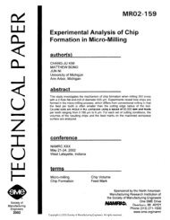
(a) A truck fender in <strong>IGES</strong> representation<br />
(b) Fender surface and its normal offset surface<br />
(c) <strong>Tool</strong> path <strong>for</strong> fender rough cutting<br />
Fig. 14 Surface of truck fender and NC tool path<br />
Move tool to safe zone between these two segments;<br />
[/* end of <strong>for</strong> *1<br />
Pass Cutter Location data to Motion Processor through<br />
Multibus;<br />
Move cutterplane to another position based on cusp error<br />
tolerance; *<br />
[ while (noLpasLalLsurface = = FALSE) 1* end of do I<br />
}/* end of main */<br />
A fender of a truck is used to generate the NC tool path<br />
based on the algorithm proposed in this paper. Figure 14 (a)<br />
shows the IOES definition data. Figure 14(b) shows the surface<br />
representation and the normal offset surface ofthis fender.<br />
The NC tool path <strong>for</strong> rough cutting is calculated, as shown in<br />
Fig. 14(c).<br />
Another part shown in Fig. 15 is used in a real cutting<br />
experiment since this part contains more gougings, which the<br />
real-<strong>time</strong> algorithm has to process correctly. When cutting a<br />
90-degree corner with a ball-end milling cutter, one would<br />
encounter the gouging problem. Using the above tool path<br />
generation algorithm, the tool paths have been generated in<br />
real <strong>time</strong> and are stored <strong>for</strong> illustration purpose. It can be seen<br />
that no overcut situations have occurred. In order to display<br />
properly, only a rough cutting tool path has been shown in<br />
Fig. 16.<br />
Actual machining has been conducted based on the following<br />
experimental conditions: (1) The radius ofthe ball-end milling<br />
Journal of Engineering <strong>for</strong> Industry<br />
Fig. 15 Computer representation of the test part<br />
Fig. 16 <strong>Tool</strong> paths <strong>for</strong> the test part generated by the developed algorithm<br />
Fig. 17 The photograph of the machined test part<br />
cutter is 3.175 mm. (2) The rough cutting is conducted with<br />
2 mm liftoff, 0.02 mm chord error, and 0.5 mm cusp error.<br />
(3) Tolerable cusp and chord errors <strong>for</strong> finishing cutting are<br />
specified to be 0.02 mm. (4) Spindle speed is 2000 rpm and<br />
feedrate is 150 ipm. (5) Workpiece material is wax. It takes<br />
less than 1 second to generate one tool path across the entire<br />
work piece surface,which contains on average more than 100<br />
cutter location points. The workpiece has a dimension of 4<br />
inches by 6 inches.<br />
Figure 17 shows the part machined using the real-<strong>time</strong> tool<br />
path generation algorithm. It can be concluded from the machined<br />
part that the developed algorithm can properly handle<br />
problems such as trimming lines, gouging detection, and control<br />
of tool step sizes in real <strong>time</strong>. The surface contouring<br />
accuracy of the machined part is also checked on a coordinate<br />
measuring machine. It is found that the surface contour error<br />
ofthe cut part is less than 0.02 mm, which is within the specified<br />
tolerance.<br />
5 Conclusion<br />
A real-<strong>time</strong> NC tool path generation algorithm has been<br />
developed. Features of this new algorithm include:<br />
(1) Three-dimensional NC tool paths can be generated in<br />
real <strong>time</strong> during cutting, which eliminates the compromise<br />
between desired surface contouring tolerances and<br />
NOVEMBER 1993, Vol. 115/485
the required memory sizes <strong>for</strong> storing off-line generated<br />
NC tool path data. This provides greatly increased surface<br />
contouring accuracy without lengthy NC code<br />
download <strong>time</strong> and huge memory storage requirements.<br />
(2) This new algorithm directly uses <strong>IGES</strong> based CAD data<br />
files as its input, which makes it compatible with a wide<br />
range of CAD software packages.<br />
(5) This new algorithm can automatically adjust its tool<br />
step size according to the change in surface curvatures,<br />
and, thus, can yield better surface smoothness and uni<strong>for</strong>mity.<br />
(4) Through computer simulation and actual machining, it<br />
has been verified that the developed real-<strong>time</strong> NC tool<br />
path generation algorithm can deal adequately with issues<br />
such as trimming lines, gouging, and adaptive tool<br />
step adjustment. Cutting results have shown that no<br />
violating conditions occurred on the machined part surfaces<br />
and the surface contour error of the cut part is<br />
less than the specified tolerance, 0.02 mm.<br />
References<br />
Anderson, R. O., 1978, "Detecting and Eliminating Collisions in NC <strong>Machining</strong>,"<br />
Computer Aided Design, Vol. 10, pp. 231-238.<br />
Armstrong, G. T., Garey, G. G., and Pennington, A. D., 1984, "Numerical<br />
Code <strong>Generation</strong> from A Geometric Modeling System," Solid Modeling By<br />
Computers, from Theory to Applications, Pickett and Boyse, eds., Plenum<br />
Press, New York, pp. 139-154.<br />
Barnhill, R. E., 1985, "Surface in Computer Aided Geometric Design; A<br />
Survey with New Results," Computer Aided Geometric Design, Vol. 2, No. 1,<br />
pp. 1-17.<br />
Bobrow, J. E., 1985, "NC Machine <strong>Tool</strong> <strong>Path</strong> <strong>Generation</strong> From CSG Part<br />
Representations," Computer-Aided Design, Vol. 17, No. 2, pp. 69-76.<br />
Boehm, W., and Farin, G., and Kallmann, J., 1984, "A Survey of Curve and<br />
Surface Methods in CAGD," Computer Aided Geometric Design, Vol. 1, No.<br />
1, pp. 1-60.<br />
Choi, B. K., Barash, M. M., and Anderson, D. C, 1984, "Automatic Recognition<br />
of Machined Surface from 3D Solid Model," Computer Aided Design,<br />
Vol. 16, No. 2, pp. 81-86.<br />
Choi, B. K., and Jun, C. S., 1989, "Ball-end Cutter Interference Avoidance<br />
in NC <strong>Machining</strong> of Sculptured <strong>Surfaces</strong>," Computer Aided Design, Vol. 21,<br />
No. 6, pp. 371-378.<br />
Choi, B. K., Lee, C. S., Hwang, J. S., and Jun, C. S., 1988, "Compound<br />
Surface Modeling and <strong>Machining</strong>," Computer Aided Design, Vol. 20, No. 3,<br />
pp. 127-136.<br />
Culbreth, D. N., 1989, "Manufacturing Model: an Integrated Approach to<br />
Planning, Design and Managing Industrial Facilities," Computer Aided Design,<br />
Vol. 21, No. 1, pp. 49-53.<br />
Drysdale, R. L. and Jerard, R. B., 1987, "Discrete Simulation of NC <strong>Machining</strong>,"<br />
Proc. ACM Symp. Computational Geometry, June.<br />
Duncan, J. P., and Mair, S. G., 1983, Sculptured <strong>Surfaces</strong> in Engineering<br />
and Medicine, Cambridge University Press.<br />
Eversheim, W., and Holz, B., 1982, "Computer Aided Programming of NC-<br />
Machine <strong>Tool</strong>s by Using the System AUTAP-NC," Annals of the CRIP, Vol.<br />
31, p. 323.<br />
Farouki, R. T., 1987, "The Approximation of Non-degenerate Offset <strong>Surfaces</strong>,"<br />
Computer Aided Design, Vol. 4, pp. 3-16.<br />
Faux, I. D., and Pratt, M. J., 1981, Computational Geometry <strong>for</strong> Design<br />
and Manufacture, John Wiley.<br />
Ferstenberg, R., Wang, K. K., and Muchstadt, J., 1986, Automatic <strong>Generation</strong><br />
of Optimized 3-Axis NC Programs Using Boundary Files, IEEE.<br />
Gregory, C. L., and Ozsoy, T. M., 1987, "NC <strong>Machining</strong> of Free Form<br />
<strong>Surfaces</strong>," Computer Aided Design, Vol. 19, No. 2, pp. 84-89.<br />
NBS, National Bureau of Standards, U.S. Department of Commerce, 1988,<br />
"Initial Graphics Exchange Specification (<strong>IGES</strong>) Version 4.0, NBSIR 88-3813.<br />
Jayaram, S., and Myklebust, A., 1990, "Automatic <strong>Generation</strong> of Geometry<br />
Interfaces Between Applications Programs and CADCAM Systems," Computer<br />
Aided Design, Vol. 22, No. 1, pp. 50-56.<br />
Jerard, R. B., Drysdale, R. L., Hauck, K., Schaudt, B., and Madgewick, J.,<br />
1989, "Methods <strong>for</strong> Detecting Errors in Numerically Controlled <strong>Machining</strong> of<br />
Sculptured <strong>Surfaces</strong>," IEEE Computer Graph. Appl., Vol. 9, No. 1.<br />
Kakazu, Y., Okino, N., and Hoshi, K., 1974, "The Penalty Method of Determining<br />
Automatically a NC Cutter <strong>Path</strong>," CIRP Conference.<br />
Mills, R. B., 1984, "Computer Graphics <strong>for</strong> NC Programming," CAE, Nov.,<br />
pp. 32-42.<br />
Oliver, J. H., and Goodman, E. D., 1990, "Direct Dimensional NC Verification,"<br />
Computer Aided Design, Vol. 22, No. 1, pp. 3-10.<br />
Persson, H., 1978, "NC <strong>Machining</strong> of Arbitrarily Shaped Pockets," CAD,<br />
Vol. 10, No. 3, May.<br />
Press, K., and Kaplansky, E., "Automated Part Programming <strong>for</strong> <strong>CNC</strong><br />
Milling By Artificial Intelligence Techniques," Journal of Manufacturing System,<br />
Vol. 4, No. 1, pp. 51-63.<br />
Suh, Y. S., and Lee, K., 1990, "NC Milling <strong>Tool</strong> <strong>Path</strong> <strong>Generation</strong> <strong>for</strong> Arbitrary<br />
Pockets Defined by Sculptured <strong>Surfaces</strong>," Computer Aided Design, Vol.<br />
22, No. 5, pp. 274-284.<br />
Thomas, S. W„ 1990, "Scanline Rendering <strong>for</strong> 3-Axis NC <strong>Tool</strong>path <strong>Generation</strong>,<br />
Simulation, and Verification," CSE-TR-43-90, The University of Michigan.<br />
Wang, K. K., and Wang, W. P., 1981, "A PADL Based Numerical Control<br />
<strong>Machining</strong> Data <strong>Generation</strong> Program," Annals of the CIRP, Vol. 30, pp. 359-<br />
362.<br />
Wang, W. P., and Wang, K. K., 1986, "<strong>Real</strong>-Time Verification of Multiaxis<br />
NC Programs with Raster Graphics," IEEE Proc. Int'l. Conf Robotics and<br />
Automation, Los Alamitos, CA, CS Press, pp. 166-171.<br />
486 / Vol. 115, NOVEMBER 1993 Transactions of the ASME