Real-time CNC Tool Path Generation for Machining IGES Surfaces
Real-time CNC Tool Path Generation for Machining IGES Surfaces
Real-time CNC Tool Path Generation for Machining IGES Surfaces

You also want an ePaper? Increase the reach of your titles
YUMPU automatically turns print PDFs into web optimized ePapers that Google loves.
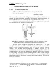
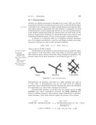
Fig. 2 Parametric Spline Surface (<strong>IGES</strong> Type 114)<br />
• Cartesian machining method. <strong>Tool</strong> paths are planned on the<br />
XY-plane of a Cartesian coordinate system. The cutter path<br />
is the intersection of the part surface and a vertical plane<br />
perpendicular to the XY-plane (Choi et al., 1988, 1989; Bobrow,<br />
1985). In this method, the cutter plane has to be a vertical<br />
plane. Because gouging points may not be on the vertical cutter<br />
plane, the search <strong>for</strong> gouging points must be per<strong>for</strong>med on<br />
the entire part surface.<br />
• Parametric machining method. <strong>Tool</strong> paths are planned on<br />
the parametric space. There are two ways to calculate the tool<br />
paths. (/) The tool is moved at equally spaced points on the<br />
w-line or y-line of the surface. Corresponding to each selected<br />
point on the u-v domain, a (x, y, z) point on the part surface<br />
can be calculated and used as tool paths. The drawback of<br />
this scheme is the difficulty of controlling the tolerance on a<br />
part surface based only on the u-v domain point interval. The<br />
equally spaced points in the parameter space may result in<br />
differently spaced points on the part surface (Bobrow, 1985).<br />
(2) The points and normal vectors on a part surface are first<br />
evaluated at predefined small intervals of both parameters u<br />
and v. The tool path is then generated by searching through<br />
this huge data array of part surface points in a given cutter<br />
plane. This method is widely used in commercial NC software.<br />
The operations of filters are per<strong>for</strong>med in order to generate<br />
the smallest tool path point and reduce the tool path data size.<br />
The filler operations are also necessary to insert points in the<br />
interval if it is not small enough. The operations of filler and<br />
filter are very <strong>time</strong> consuming.<br />
All these off-line tool path generation methods have a common<br />
drawback. There is always a tradeoff between the level<br />
of path precision, in terms of the coarseness of tool path points<br />
on a sculptured surface, and the memory requirement.<br />
This paper presents a new method <strong>for</strong> the real-<strong>time</strong> generation<br />
of NC tool paths to produce free-<strong>for</strong>m sculptured surfaces<br />
on a 3-axis milling machine. This method is intended to<br />
eliminate the need <strong>for</strong> the tradeoff between path precision and<br />
memory requirement. The unique feature of this real-<strong>time</strong> path<br />
generation method is that it can generate as many points as<br />
needed within each computational cycle <strong>time</strong>. The method is<br />
designed to generate NC tool paths directly from <strong>IGES</strong> 114<br />
data files since the <strong>IGES</strong> is the main standard electronic data<br />
translator recognized by the ANSI.<br />
A new <strong>CNC</strong> controller is being developed based on the<br />
Multibus II structure and the iRMX-III operating system. The<br />
controller is a true multi-processor and multi-tasking system.<br />
One of the processors in this controller is used as a Free-Form<br />
Surface Milling <strong>Tool</strong> <strong>Path</strong> Processor, which can read <strong>IGES</strong><br />
data directly from a CAD data file and generate the <strong>CNC</strong> tool<br />
path during machining operations. The tool path data is then<br />
passed to motion controller processors through the Multibus<br />
in real <strong>time</strong>.<br />
The definitions of <strong>IGES</strong> surfaces and the derivation of their<br />
offset surfaces are given in Section 2. The proposed tool path<br />
generation algorithms <strong>for</strong> free-<strong>for</strong>m sculptured surfaces are<br />
presented in Section 3. The issues of tool path planning, tool<br />
step calculation, gouging detection, tool path interval, and<br />
trimmed surfaces are discussed in detail. These developed algorithms<br />
are verified through actual cutting tests, and the<br />
results are presented in Section 4.<br />
Journal of Engineering <strong>for</strong> Industry<br />
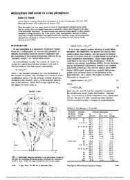
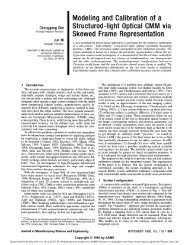
Fig. 3 <strong>Tool</strong> position definitions<br />
2 <strong>IGES</strong> <strong>Surfaces</strong> and Their Offset <strong>Surfaces</strong><br />
<strong>IGES</strong> is a widely used CAD data file structure. All major<br />
CAD software packages support the <strong>IGES</strong> input and output<br />
<strong>for</strong>mat. The <strong>IGES</strong> data <strong>for</strong>mat is used as the input data <strong>for</strong>mat<br />
of this new real-<strong>time</strong> tool path generation method.<br />
The focus of this paper is on the machining of free-<strong>for</strong>m<br />
parametric surfaces on a 3-axis milling machine. It is assumed<br />
that the surfaces can be reached by the milling cutter in the<br />
positive Z direction. The entity 114 in <strong>IGES</strong> can represent these<br />
free-<strong>for</strong>m parametric surfaces. <strong>IGES</strong> gives all in<strong>for</strong>mation used<br />
to define the free-<strong>for</strong>m parametric spline surfaces. A detailed<br />
definition of <strong>IGES</strong> surfaces can be obtained from Ref. NBS<br />
(1988). The free-<strong>for</strong>m parametric spline surface shown in Fig.<br />
2 can be expressed as:<br />
S(u,v)=x(u,v)i+y(u,v)j+z(u,v)k (1)<br />
Let S(u,v) be a part surface parameterized and oriented by<br />
N(«, v), a differentiable normal vector defined on the whole<br />
surface. An offset surface to S is a parameterized surface O<br />
(u, v) given by:<br />
0(u,v)=S(u,v)+f(d)-N(u,v), (2)<br />
where<br />
dS(u,v) dS(u,v)<br />
du dv<br />
N(u,v)=<br />
dS(u,v) dS(u,v)<br />
du dv<br />
and f(d) is an offset distance function and a constant <strong>for</strong><br />
machining with a ball-end cutter. With more general cutter<br />
geometry and 5-axis machining, further investigation is necessary<br />
to determine this offset distance function.<br />
Cutting tools are not an idealized geometrical point and have<br />
a finite radius ball tip as shown in Fig. 3, where point P is<br />
called the cutter contact (CC) position and point C is the<br />
cutter location (CL) and T stands <strong>for</strong> the tip position. The<br />
tool path is often referred to as the cutter location (CL) data,<br />
which are to be generated from designed part surface data and<br />
used by the <strong>CNC</strong> controller to drive the cutting tool.<br />
3 Proposed <strong>Tool</strong> <strong>Path</strong> <strong>Generation</strong> Algorithm <strong>for</strong> Free-<br />
Form <strong>Surfaces</strong><br />
The basic requirements <strong>for</strong> the real-<strong>time</strong> tool path generation<br />
are that (1) the tool path on a cutter plane should nave no<br />
gouging problem with points that are not in the cutter plane,<br />
(2) the length of tool steps should be adjustable based on the<br />
tolerance and condition of the surface to be machined, and<br />
(J) the algorithm should be able to handle the trimmed curves<br />
on the surfaces. The following issues should be addressed:<br />
9 <strong>Tool</strong> path planning<br />
• <strong>Tool</strong> step length calculation<br />
• Gouging problem<br />
• <strong>Tool</strong> path interval<br />
• Trimmed surface.<br />
3.1 <strong>Tool</strong> <strong>Path</strong> Planning. The Cartesian and parametric<br />
machining methods mentioned above are combined in the development<br />
of the proposed new real-<strong>time</strong> path generation al-<br />
NOVEMBER 1993, Vol. 115 / 481