Real-time CNC Tool Path Generation for Machining IGES Surfaces
Real-time CNC Tool Path Generation for Machining IGES Surfaces
Real-time CNC Tool Path Generation for Machining IGES Surfaces

You also want an ePaper? Increase the reach of your titles
YUMPU automatically turns print PDFs into web optimized ePapers that Google loves.
,<br />
(ul •vl)<br />
li<br />
\<br />
Cut er path in the<br />
u-v domain<br />
\<br />
<br />
rang<br />
i<br />
Vi<br />
(u .vl)<br />
-f-<br />
S<br />
s<br />
-i \<br />
S"<br />
\<br />
(u2,v2) u range of u = u2-ul<br />
(u2,v2)<br />
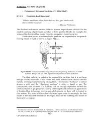
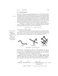
Fig. 7 Segmentation of tool path in parameter u-v domain<br />
index point<br />
normal vector of<br />
cutter plane<br />
offset surface<br />
offset surface<br />
surface<br />
\<br />
index points 'n index P 01nt<br />
normal vector of<br />
cutter plane<br />
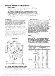
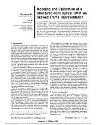
Fig. 8 Triple product of vectors <strong>for</strong> curve sorting<br />
D„ r, and L,- will be updated to their new values at the new<br />
position, and Eq. (7) will be applied to give a new total number<br />
of tool steps, Nj.<br />
After the total number of tool steps is determined, the tool<br />
path in the u-v domain will be divided into N, segments. It is<br />
best to divide the tool path in the u-v domain along an axis<br />
that has a larger parameter range. For example, as shown in<br />
Fig. 7, the tool path from (ul, v\) to («2, v2) has a relatively<br />
larger change along the v axis. There<strong>for</strong>e, the division tool<br />
path will be made along the v axis.<br />
or<br />
AVJ =<br />
AW; =<br />
(Vj-V2)<br />
N,<br />
(Ui-U2)<br />
This method is fast and easy to implement. It can adjust the<br />
parameter interval based on the curvature of the surface.<br />
3.3 Gouging Problem. After calculating the intersection<br />
between the offset surface and the cutter planes, the tool path<br />
will become a series of curves that are in the cutter planes.<br />
These curves will discontinue at the joint section of the surfaces.<br />
Algorithms must be developed to deal with these discontinuities.<br />
Curve Sorting. The order of the surfaces given in <strong>IGES</strong><br />
<strong>for</strong>mat is not arranged by the geometric structure and the<br />
in<strong>for</strong>mation about how to link these curves is not provided by<br />
<strong>IGES</strong>. A curve sorting algorithm is developed to find the connection<br />
between different intersection curves. The objective of<br />
the curve sorting algorithm is to determine which two curves<br />
ought to be connected and how the ends of these two curves<br />
are connected.<br />
Two additional orientation index points are added to each<br />
intersection curve in this sorting process. These index points<br />
are the intersection points of the cutter plane and the part<br />
surface boundary, representing the starting and ending points<br />
of a part surface boundary. The ending point of one surface<br />
will be the starting point of another surface if they are connected<br />
to each other.<br />
In order to determine whether the index points are put in<br />
the proper positions or not, the triple product of vectors nl,<br />
nl', and n is used to check the relative positions of the starting<br />
and ending points of both part surface and offset surface, as<br />
shown in Fig. 8. Vector n is the surface normal of the cutter<br />
N,<br />
Journal of Engineering <strong>for</strong> Industry<br />
t<br />
1<br />
fair<br />
(8)<br />
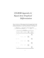
Fig. 9 Connection of tool paths in the cutter plane<br />
Fig. 10 Determination of filleting or trimming conditions between two<br />
tool path segments<br />
plane (which is the paper plane in the drawing), and vectors<br />
nl and nl' are the vectors connecting the starting and ending<br />
index points, respectively, to the edges of the offset surface.<br />
If n«(nl x nl') < 0, the index points on a part surface is<br />
properly connected to the starting and ending points on its<br />
offset surface. If n»(nl x nl') > 0, these points are not<br />
properly connected.<br />
After the index points associated with each tool path segment<br />
are properly labeled with a starting or ending mark, they are<br />
used to identify the connection between different tool path<br />
segments. If the ending index point of a tool path segment is<br />
determined to be equal to the starting index point of another<br />
segment, these two segments should be connected together.<br />
Another faster method to sort the order of the curves is to<br />
sort them based on the distances from their starting and ending<br />
points to a given fixed reference point. These distances are<br />
calculated using Eq. (9).<br />
DISS (i)= ^/(Xs(i)-Xr) 2 +(Ys(i)-Yr) 2 +(ZAi)-Zr) 2<br />
DISe(i) -•y[(x. (i)-Xr) 2 +(Ye(i) Yr) 2 +(Ze(i)~Zr) 2 ,<br />
(9)<br />
where subscript s stands <strong>for</strong> starting point, subscript e stands<br />
<strong>for</strong> ending point, and subscript r stands <strong>for</strong> the reference point.<br />
For instance, let us assume that the fixed reference point is<br />
on the far left side of all curves and tool path segments starting<br />
from left to right when properly oriented. Then the distance<br />
from the starting point of the tool path segment to the reference<br />
point should be smaller than that from the ending point. Otherwise,<br />
the tool path segment is placed in a wrong orientation.<br />
By checking the distances from both the starting and ending<br />
points of each tool path segment, its orientation can be determined.<br />
After sorting the curves, all calculated tool path curves can<br />
be linked from the ending index point of one curve to the<br />
starting index point of the next curve, as shown in Fig. 9.<br />
Connecting <strong>Surfaces</strong>. It can be seen from Fig. 9 that <strong>for</strong><br />
two surfaces with a convex joint there is a gap between their<br />
offset surfaces and <strong>for</strong> two surfaces with a concave joint there<br />
is'overlap between their offset surfaces. In order to connect<br />
these tool paths, corner fillets and/or edge removals are necessary.<br />
To check if the tool path segment needs to be removed<br />
or filleted, another triple product is used. If n«(nl x n2) <<br />
0, an interpolation or fillet is needed between these two tool<br />
path segments, as shown in Fig. 10(a). If n»(nl x n2) > 0,<br />
these two tool path segments are gouged, and a removal operation<br />
is needed, as shown in Fig. \Q(b).<br />
In either case, an intersection point, P0, should be determined,<br />
as shown in Fig. 11. If a removal operation is required,<br />
NOVEMBER 1993, Vol. 115/483