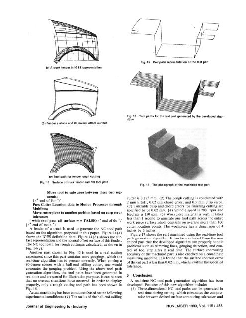
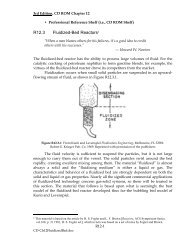
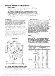
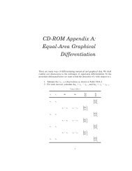
(a) A truck fender in <strong>IGES</strong> representation (b) Fender surface and its normal offset surface (c) <strong>Tool</strong> path <strong>for</strong> fender rough cutting Fig. 14 Surface of truck fender and NC tool path Move tool to safe zone between these two segments; [/* end of <strong>for</strong> *1 Pass Cutter Location data to Motion Processor through Multibus; Move cutterplane to another position based on cusp error tolerance; * [ while (noLpasLalLsurface = = FALSE) 1* end of do I }/* end of main */ A fender of a truck is used to generate the NC tool path based on the algorithm proposed in this paper. Figure 14 (a) shows the IOES definition data. Figure 14(b) shows the surface representation and the normal offset surface ofthis fender. The NC tool path <strong>for</strong> rough cutting is calculated, as shown in Fig. 14(c). Another part shown in Fig. 15 is used in a real cutting experiment since this part contains more gougings, which the real-<strong>time</strong> algorithm has to process correctly. When cutting a 90-degree corner with a ball-end milling cutter, one would encounter the gouging problem. Using the above tool path generation algorithm, the tool paths have been generated in real <strong>time</strong> and are stored <strong>for</strong> illustration purpose. It can be seen that no overcut situations have occurred. In order to display properly, only a rough cutting tool path has been shown in Fig. 16. Actual machining has been conducted based on the following experimental conditions: (1) The radius ofthe ball-end milling Journal of Engineering <strong>for</strong> Industry Fig. 15 Computer representation of the test part Fig. 16 <strong>Tool</strong> paths <strong>for</strong> the test part generated by the developed algorithm Fig. 17 The photograph of the machined test part cutter is 3.175 mm. (2) The rough cutting is conducted with 2 mm liftoff, 0.02 mm chord error, and 0.5 mm cusp error. (3) Tolerable cusp and chord errors <strong>for</strong> finishing cutting are specified to be 0.02 mm. (4) Spindle speed is 2000 rpm and feedrate is 150 ipm. (5) Workpiece material is wax. It takes less than 1 second to generate one tool path across the entire work piece surface,which contains on average more than 100 cutter location points. The workpiece has a dimension of 4 inches by 6 inches. Figure 17 shows the part machined using the real-<strong>time</strong> tool path generation algorithm. It can be concluded from the machined part that the developed algorithm can properly handle problems such as trimming lines, gouging detection, and control of tool step sizes in real <strong>time</strong>. The surface contouring accuracy of the machined part is also checked on a coordinate measuring machine. It is found that the surface contour error ofthe cut part is less than 0.02 mm, which is within the specified tolerance. 5 Conclusion A real-<strong>time</strong> NC tool path generation algorithm has been developed. Features of this new algorithm include: (1) Three-dimensional NC tool paths can be generated in real <strong>time</strong> during cutting, which eliminates the compromise between desired surface contouring tolerances and NOVEMBER 1993, Vol. 115/485
the required memory sizes <strong>for</strong> storing off-line generated NC tool path data. This provides greatly increased surface contouring accuracy without lengthy NC code download <strong>time</strong> and huge memory storage requirements. (2) This new algorithm directly uses <strong>IGES</strong> based CAD data files as its input, which makes it compatible with a wide range of CAD software packages. (5) This new algorithm can automatically adjust its tool step size according to the change in surface curvatures, and, thus, can yield better surface smoothness and uni<strong>for</strong>mity. (4) Through computer simulation and actual machining, it has been verified that the developed real-<strong>time</strong> NC tool path generation algorithm can deal adequately with issues such as trimming lines, gouging, and adaptive tool step adjustment. Cutting results have shown that no violating conditions occurred on the machined part surfaces and the surface contour error of the cut part is less than the specified tolerance, 0.02 mm. References Anderson, R. O., 1978, "Detecting and Eliminating Collisions in NC <strong>Machining</strong>," Computer Aided Design, Vol. 10, pp. 231-238. Armstrong, G. T., Garey, G. G., and Pennington, A. D., 1984, "Numerical Code <strong>Generation</strong> from A Geometric Modeling System," Solid Modeling By Computers, from Theory to Applications, Pickett and Boyse, eds., Plenum Press, New York, pp. 139-154. Barnhill, R. E., 1985, "Surface in Computer Aided Geometric Design; A Survey with New Results," Computer Aided Geometric Design, Vol. 2, No. 1, pp. 1-17. Bobrow, J. E., 1985, "NC Machine <strong>Tool</strong> <strong>Path</strong> <strong>Generation</strong> From CSG Part Representations," Computer-Aided Design, Vol. 17, No. 2, pp. 69-76. Boehm, W., and Farin, G., and Kallmann, J., 1984, "A Survey of Curve and Surface Methods in CAGD," Computer Aided Geometric Design, Vol. 1, No. 1, pp. 1-60. Choi, B. K., Barash, M. M., and Anderson, D. C, 1984, "Automatic Recognition of Machined Surface from 3D Solid Model," Computer Aided Design, Vol. 16, No. 2, pp. 81-86. Choi, B. K., and Jun, C. S., 1989, "Ball-end Cutter Interference Avoidance in NC <strong>Machining</strong> of Sculptured <strong>Surfaces</strong>," Computer Aided Design, Vol. 21, No. 6, pp. 371-378. Choi, B. K., Lee, C. S., Hwang, J. S., and Jun, C. S., 1988, "Compound Surface Modeling and <strong>Machining</strong>," Computer Aided Design, Vol. 20, No. 3, pp. 127-136. Culbreth, D. N., 1989, "Manufacturing Model: an Integrated Approach to Planning, Design and Managing Industrial Facilities," Computer Aided Design, Vol. 21, No. 1, pp. 49-53. Drysdale, R. L. and Jerard, R. B., 1987, "Discrete Simulation of NC <strong>Machining</strong>," Proc. ACM Symp. Computational Geometry, June. Duncan, J. P., and Mair, S. G., 1983, Sculptured <strong>Surfaces</strong> in Engineering and Medicine, Cambridge University Press. Eversheim, W., and Holz, B., 1982, "Computer Aided Programming of NC- Machine <strong>Tool</strong>s by Using the System AUTAP-NC," Annals of the CRIP, Vol. 31, p. 323. Farouki, R. T., 1987, "The Approximation of Non-degenerate Offset <strong>Surfaces</strong>," Computer Aided Design, Vol. 4, pp. 3-16. Faux, I. D., and Pratt, M. J., 1981, Computational Geometry <strong>for</strong> Design and Manufacture, John Wiley. Ferstenberg, R., Wang, K. K., and Muchstadt, J., 1986, Automatic <strong>Generation</strong> of Optimized 3-Axis NC Programs Using Boundary Files, IEEE. Gregory, C. L., and Ozsoy, T. M., 1987, "NC <strong>Machining</strong> of Free Form <strong>Surfaces</strong>," Computer Aided Design, Vol. 19, No. 2, pp. 84-89. NBS, National Bureau of Standards, U.S. Department of Commerce, 1988, "Initial Graphics Exchange Specification (<strong>IGES</strong>) Version 4.0, NBSIR 88-3813. Jayaram, S., and Myklebust, A., 1990, "Automatic <strong>Generation</strong> of Geometry Interfaces Between Applications Programs and CADCAM Systems," Computer Aided Design, Vol. 22, No. 1, pp. 50-56. Jerard, R. B., Drysdale, R. L., Hauck, K., Schaudt, B., and Madgewick, J., 1989, "Methods <strong>for</strong> Detecting Errors in Numerically Controlled <strong>Machining</strong> of Sculptured <strong>Surfaces</strong>," IEEE Computer Graph. Appl., Vol. 9, No. 1. Kakazu, Y., Okino, N., and Hoshi, K., 1974, "The Penalty Method of Determining Automatically a NC Cutter <strong>Path</strong>," CIRP Conference. Mills, R. B., 1984, "Computer Graphics <strong>for</strong> NC Programming," CAE, Nov., pp. 32-42. Oliver, J. H., and Goodman, E. D., 1990, "Direct Dimensional NC Verification," Computer Aided Design, Vol. 22, No. 1, pp. 3-10. Persson, H., 1978, "NC <strong>Machining</strong> of Arbitrarily Shaped Pockets," CAD, Vol. 10, No. 3, May. Press, K., and Kaplansky, E., "Automated Part Programming <strong>for</strong> <strong>CNC</strong> Milling By Artificial Intelligence Techniques," Journal of Manufacturing System, Vol. 4, No. 1, pp. 51-63. Suh, Y. S., and Lee, K., 1990, "NC Milling <strong>Tool</strong> <strong>Path</strong> <strong>Generation</strong> <strong>for</strong> Arbitrary Pockets Defined by Sculptured <strong>Surfaces</strong>," Computer Aided Design, Vol. 22, No. 5, pp. 274-284. Thomas, S. W„ 1990, "Scanline Rendering <strong>for</strong> 3-Axis NC <strong>Tool</strong>path <strong>Generation</strong>, Simulation, and Verification," CSE-TR-43-90, The University of Michigan. Wang, K. K., and Wang, W. P., 1981, "A PADL Based Numerical Control <strong>Machining</strong> Data <strong>Generation</strong> Program," Annals of the CIRP, Vol. 30, pp. 359- 362. Wang, W. P., and Wang, K. K., 1986, "<strong>Real</strong>-Time Verification of Multiaxis NC Programs with Raster Graphics," IEEE Proc. Int'l. Conf Robotics and Automation, Los Alamitos, CA, CS Press, pp. 166-171. 486 / Vol. 115, NOVEMBER 1993 Transactions of the ASME