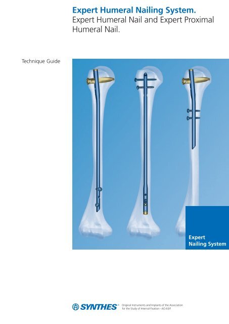
Expert Humeral Nailing System. Expert Humeral Nail and ... - Synthes
Expert Humeral Nailing System. Expert Humeral Nail and ... - Synthes
Expert Humeral Nailing System. Expert Humeral Nail and ... - Synthes

You also want an ePaper? Increase the reach of your titles
YUMPU automatically turns print PDFs into web optimized ePapers that Google loves.
Technique Guide<br />
<strong>Expert</strong> <strong>Humeral</strong> <strong><strong>Nail</strong>ing</strong> <strong>System</strong>.<br />
<strong>Expert</strong> <strong>Humeral</strong> <strong>Nail</strong> <strong>and</strong> <strong>Expert</strong> Proximal<br />
<strong>Humeral</strong> <strong>Nail</strong>.<br />
<strong>Expert</strong><br />
<strong><strong>Nail</strong>ing</strong> <strong>System</strong>
Table of Contents<br />
Introduction<br />
Technique Guide<br />
Product Information<br />
Image intensifier control<br />
Warning<br />
This description is not sufficient for immediate application of<br />
the instrumentation. Instruction by a surgeon experienced in<br />
h<strong>and</strong>ling this instrumentation is highly recommended.<br />
Cleaning of instruments<br />
For detailed information please refer to “Reprocessing,<br />
Care <strong>and</strong> Maintenance of <strong>Synthes</strong> Instruments”,<br />
Article No. 035.000.090.<br />
Features 2<br />
AO ASIF Principles of Internal Fixation 4<br />
Indications 5<br />
<strong>Expert</strong> <strong>Humeral</strong> <strong>Nail</strong> Antegrade Insertion 6<br />
Locking with Spiral Blade 16<br />
Locking with Screws (St<strong>and</strong>ard Locking) 30<br />
<strong>Expert</strong> <strong>Humeral</strong> <strong>Nail</strong> Retrograde Insertion 41<br />
<strong>Expert</strong> Proximal <strong>Humeral</strong> <strong>Nail</strong> 59<br />
Implant Removal 77<br />
Implants 80<br />
Instruments 83<br />
Bibliography 89<br />
<strong>Synthes</strong> 1
Features<br />
Advanced proximal locking<br />
Using a spiral blade or locking screws<br />
enables the optimal locking<br />
for every anatomical situation <strong>and</strong><br />
fracture type.<br />
Spiral blade<br />
– Angular stable locking in the humeral<br />
head<br />
– Increased surface area provides a<br />
better grip even in an osteopenic<br />
humeral head<br />
Locking screws<br />
– Possibility of interfragmentary<br />
compression for enhanced<br />
stabilization of transverse <strong>and</strong><br />
short oblique fractures<br />
Improved Stability<br />
End cap<br />
– Allows angular stable locking of the<br />
spiral blade<br />
– <strong>Nail</strong> can be extended up to 15 mm<br />
– Prevents ingrowth of tissues<br />
<strong>and</strong> facilitates nail extraction<br />
– Self-holding Stardrive recess that<br />
allows the end cap to be easily <strong>and</strong><br />
reliably picked up<br />
0 mm 5 mm 10 mm 15 mm<br />
Stardrive ®<br />
T25<br />
2 <strong>Synthes</strong> <strong>Expert</strong> <strong>Humeral</strong> <strong><strong>Nail</strong>ing</strong> <strong>System</strong> Technique Guide<br />
This patient has some Sy nthes® locking screws with h exalobular in ternal drive ac cording to EN ISO 10664
One system for humeral fractures<br />
– Two nails that can be used for many<br />
types of fractures<br />
– <strong>Expert</strong> Proximal <strong>Humeral</strong> <strong>Nail</strong> for<br />
proximal fractures<br />
– <strong>Expert</strong> <strong>Humeral</strong> <strong>Nail</strong> for diaphyseal<br />
<strong>and</strong> proximal-diaphyseal combined<br />
fractures<br />
– Can be used for both left <strong>and</strong> right<br />
humerus<br />
– Cannulated nails for easy guided<br />
insertion<br />
– <strong>Expert</strong> <strong>Humeral</strong> <strong>Nail</strong> is for both<br />
antegrade <strong>and</strong> retrograde access<br />
Improved Stability<br />
Locking screw<br />
– Double thread for more contact<br />
points leading to enhanced stability<br />
– Thread closer to screw head which<br />
pro vides better bone purchase <strong>and</strong><br />
improved stability<br />
– Titanium alloy TAN for improved<br />
mechanical <strong>and</strong> fatigue properties<br />
– Self-holding Stardrive recess for<br />
effortless <strong>and</strong> secure pick-up locking<br />
screw<br />
Distal locking<br />
– <strong>Expert</strong> Proximal <strong>Humeral</strong> <strong>Nail</strong>:<br />
Targeted distal locking<br />
– <strong>Expert</strong> <strong>Humeral</strong> <strong>Nail</strong>:<br />
New positions <strong>and</strong> angulations of the<br />
locking holes for optimal positioning<br />
of the locking screws in both<br />
approaches. Secure fixation of even<br />
short distal or proximal fragments.<br />
Stardrive ®<br />
T25<br />
This patient has some Sy nthes® locking screws with h exalobular in ternal drive ac cording to EN ISO 10664<br />
<strong>Synthes</strong> 3
AO ASIF Principles of<br />
Internal Fixation<br />
In 1958, the AO/ASIF (Association for the Study of Internal<br />
Fixation) formulated four basic principles which have<br />
become the guidelines for internal fixation in general, <strong>and</strong><br />
intramedullary nailing in particular:<br />
Fracture reduction to restore anatomical relationships<br />
For shaft fractures it is important to restore length, rotation<br />
<strong>and</strong> angulation. For metaphyseal fractures the restoration of<br />
exact anatomical relations is more important. Before the insertion<br />
of the nail the fracture can be reduced manually, using<br />
a reduction table, an external fixator or a distractor. A<br />
guide wire marks the prescribed path into the intramedullary<br />
canal <strong>and</strong> secures alignment of the fragments while the cannulated<br />
nail is being inserted over the wire. The nail insertion<br />
is generally monitored using x-rays. The nail is then locked<br />
proximally <strong>and</strong> distally to the bone fragments in order to<br />
hold the reduction.<br />
Stability as required by the nature <strong>and</strong> the localization<br />
of the fracture<br />
An intramedullary nail acts as an internal splint that controls<br />
but does not prevent microscopic fragment movements.<br />
It provides a relative stability that leads to an indirect healing<br />
through callus formation. The <strong>Expert</strong> <strong>Humeral</strong> <strong>Nail</strong> provides<br />
secure fixation of diaphyseal fractures using an antegrade or<br />
a retrograde approach. The spiral blade that is used with an<br />
end cap provides a locked, fixed-angle construction.<br />
Preservation of blood supply<br />
Indirect reduction <strong>and</strong> a minimal invasive fixation technique<br />
allow for soft tissue respecting surgery. The instruments <strong>and</strong><br />
implants in the <strong>Expert</strong> <strong>Humeral</strong> <strong>Nail</strong> system permit a more<br />
percutaneous technique which is less injurious tissue than<br />
other treatment methods. The intramedullary approach results<br />
in less blood loss than plate fixation.<br />
Early mobilization<br />
Intramedullary nailing, combined with AO technique, provides<br />
relatively stable fracture fixation with minimal trauma<br />
to the fragments blood supply. This helps improve the<br />
environment for bone healing, accelerating the patient’s return<br />
to previous mobility <strong>and</strong> function. The unique concept<br />
of spiral blade fixation promotes stability even in meta physeal<br />
fractures <strong>and</strong>/or osteoporotic bone.<br />
4 <strong>Synthes</strong> <strong>Expert</strong> <strong>Humeral</strong> <strong><strong>Nail</strong>ing</strong> <strong>System</strong> Technique Guide
Indications<br />
<strong>Expert</strong> <strong>Humeral</strong> <strong>Nail</strong>: locking with spiral blade<br />
or screws<br />
The range of indications for the <strong>Expert</strong> <strong>Humeral</strong> <strong>Nail</strong> in -<br />
cludes humeral shaft fractures down to approx. 5 cm<br />
proximal to the olecranon fossa with closed epiphyseal<br />
lines (AO/ASIF classification: A–C) for:<br />
– Stable or unstable fractures<br />
– Pathological fractures<br />
– Refractures, some fractures with delayed healing <strong>and</strong><br />
pseudoarthroses<br />
The <strong>Expert</strong> <strong>Humeral</strong> <strong>Nail</strong> can be inserted into the humeral<br />
shaft in both antegrade <strong>and</strong> retrograde directions. It can be<br />
used universally for either the left or right humerus.<br />
<strong>Expert</strong> Proximal <strong>Humeral</strong> <strong>Nail</strong>: st<strong>and</strong>ard locking with<br />
spiral blade<br />
The range of indications for the <strong>Expert</strong> Proximal <strong>Humeral</strong> <strong>Nail</strong><br />
includes humerus fractures in adults in the subcapital area<br />
(AO/ASIF classification: A2, A3), or with concurrent avulsion<br />
of the greater tuberosity (AO/ASIF classification: Extra-articular<br />
bifocal fractures B1, B2, B3) for:<br />
– Stable or unstable fractures<br />
– Pathological fractures<br />
– Refractures, some fractures with delayed healing <strong>and</strong><br />
pseudoarthroses<br />
In certain cases, this technique can also be suitable for proximal<br />
articular fractures (AO classification: C fractures), provided<br />
that the domed head fragment is large enough <strong>and</strong><br />
that it is not itself fractured.<br />
The <strong>Expert</strong> Proximal <strong>Humeral</strong> <strong>Nail</strong> is inserted antegrade into<br />
the proximal humeral shaft <strong>and</strong> can be used universally for<br />
either the left or right humerus.<br />
<strong>Synthes</strong> 5
<strong>Expert</strong> <strong>Humeral</strong> <strong>Nail</strong><br />
Antegrade Insertion<br />
1<br />
Position the patient<br />
Position the patient in the “Beach Chair” position on a<br />
shoulder table. Alternatively, position the patient on his/her<br />
back with the upper body elevated at an angle of 30°. Support<br />
the shoulder with pads. The operating table must be radio<br />
lucent in the shoulder area or else the corresponding<br />
table section should be removable. It must be possible to<br />
view the whole upper arm including the elbow <strong>and</strong> the<br />
humeral head in two planes in the image intensifier. Support<br />
the fractured arm on a side rest.<br />
A modified lateral position on a completely radiolucent OR<br />
table can also be used. Position the C-arm to enable visualization<br />
of the entire humerus in the AP <strong>and</strong> lateral planes.<br />
Place the C-arm opposite the surgeon, perpendicular to the<br />
longitudinal axis of the humeral shaft in the AP view.<br />
Obtain a scapular “Y” lateral view by bringing the C-arm<br />
through a 90° arc <strong>and</strong> projecting the beam directly at the<br />
glenoid.<br />
6 <strong>Synthes</strong> <strong>Expert</strong> <strong>Humeral</strong> <strong><strong>Nail</strong>ing</strong> <strong>System</strong> Technique Guide
2<br />
Confirm nail length<br />
Instrument<br />
03.010.022 Radiographic Ruler for <strong>Expert</strong> <strong>Humeral</strong> <strong>Nail</strong><br />
The approximate nail length can be determined preoperatively.<br />
Measure the length of the unfractured humerus from<br />
its head to the olecranon fossa <strong>and</strong> deduct 3–5 cm from the<br />
measured distance.<br />
Important: The length can be determined correctly on the<br />
fractured arm only if the fracture is first correctly reduced.<br />
Position the image intensifier for an AP view of the proximal<br />
humerus. Using long holding forceps, hold the Radiographic<br />
Ruler for <strong>Expert</strong> <strong>Humeral</strong> <strong>Nail</strong> parallel to the humerus so that<br />
the proximal locking slot symbolized on the ruler is located at<br />
the correct point against the proximal humerus. Mark the<br />
skin over the proximal humerus at the “top of the nail” symbolized<br />
on the ruler.<br />
<strong>Synthes</strong> 7
<strong>Expert</strong> <strong>Humeral</strong> <strong>Nail</strong><br />
Antegrade insertion<br />
Position the image intensifier over the distal humerus, place<br />
the symbolized nail end of the ruler at the marked skin site<br />
<strong>and</strong> record an AP image. Check the reduction <strong>and</strong> read off<br />
the nail length from the image of the ruler.<br />
Note: The nail tip should be positioned at least 25 mm away<br />
from the cranial boundary of the olecranon fossa.<br />
Note: Potential of compression must be taken into account<br />
when determining the nail length <strong>and</strong> a correspondingly<br />
shorter nail should be chosen. The locking screw in the compression<br />
slot can move by up to 8 mm distally.<br />
3<br />
Confirm nail diameter<br />
Instrument<br />
03.010.023 Radiographic Medullary Canal Estimator<br />
Position the image intensifier for a lateromedial view of the<br />
humerus. Hold the radiographic medullary canal estimator<br />
over the humerus with the diameter gauge centered over the<br />
medullary canal at the narrowest part that will contain the<br />
nail. Read the diameter measurement on the circular indicator<br />
that fills the canal.<br />
Important: The ruler is not at the same level as the humerus,<br />
<strong>and</strong> this will affect the accuracy of the measurement.<br />
8 <strong>Synthes</strong> <strong>Expert</strong> <strong>Humeral</strong> <strong><strong>Nail</strong>ing</strong> <strong>System</strong> Technique Guide
4<br />
Determine entry point<br />
In certain cases after a closed reduction, the humeral head<br />
may need to be fixed temporarily with a raspatory or a<br />
Kirschner wire. The correct head position is visible in the AP<br />
view by ensuring the maximum humeral head diameter.<br />
To obtain this, the arm should be positioned in approximately<br />
25° of external rotation.<br />
Make the initial incision anterolateral to the acromion<br />
process <strong>and</strong> split the deltoid muscle longitudinally. Palpate<br />
the greater tuberosity, identify – but do not expose – the<br />
supraspinatus tendon <strong>and</strong> split the mid section lengthwise.<br />
Avoid any additional injury to the rotator cuff at all costs. The<br />
arm can be adducted across the chest in order to gain better<br />
access to the proximal humerus.<br />
The antegrade insertion point for the <strong>Expert</strong> <strong>Humeral</strong> <strong>Nail</strong> is<br />
located on the extended axis of the central humeral shaft in<br />
the lateral view <strong>and</strong> at the bone-cartilage transition of the<br />
humeral head in the AP view <strong>and</strong> not on the greater tuberosity,<br />
otherwise the tendon attachment of the supraspinatus<br />
will be affected. With the humeral head correctly positioned,<br />
the point is located just in front of, or below, the tip of the<br />
acromion process. Find this position under the image intensifier<br />
using a 2.5 mm Kirschner wire.<br />
Important: In case of greater tubercle fracture (B Type) use<br />
a slightly more medial entry point in order to avoid insertion<br />
through the fracture <strong>and</strong> subsequent lateralization of the<br />
shaft to the proximal fragment.<br />
Entry<br />
Portal<br />
Incision<br />
Acromion<br />
Clavicle<br />
<strong>Synthes</strong> 9
<strong>Expert</strong> <strong>Humeral</strong> <strong>Nail</strong><br />
Antegrade insertion<br />
5<br />
Insert Kirschner wire<br />
Instruments<br />
292.260 Kirschner wire � 2.5 mm with trocar tip,<br />
length 280 mm, Stainless Steel<br />
393.105 Universal Chuck, small, with T-H<strong>and</strong>le<br />
Using the small universal chuck with T-H<strong>and</strong>le, insert a<br />
2.5 mm Kirschner wire at the appropriate insertion point in<br />
the proximal humerus <strong>and</strong> advance it in the medullary canal.<br />
Check the position of the Kirschner wire under the image<br />
intensifier in both the frontal <strong>and</strong> sagittal planes.<br />
10 <strong>Synthes</strong> <strong>Expert</strong> <strong>Humeral</strong> <strong><strong>Nail</strong>ing</strong> <strong>System</strong> Technique Guide
6a<br />
Open medullary canal – awl<br />
Instrument<br />
03.010.039 Awl, cannulated<br />
Place the cannulated awl over the Kirschner wire to the<br />
bone. Use a twisting motion to advance the awl. Remove the<br />
awl <strong>and</strong> the Kirschner wire.<br />
Note: Dispose of the K-wire. Do not reuse.<br />
Important: Take care not to plunge the awl into the fracture<br />
site since this may displace the fracture.<br />
6b<br />
Open medullary canal – drill bit<br />
Alternative instruments<br />
360.050 Drill Bit � 10.0 mm, cannulated, length<br />
190/140 mm, 3-flute, for Jacobs Chuck<br />
03.010.038 Protection Sleeve 10.0<br />
Pass the drill bit over the Kirschner wire <strong>and</strong> through the<br />
protection sleeve to the bone. Drill to the depth of the<br />
medullary canal. Remove the drill bit <strong>and</strong> the Kirschner wire.<br />
Note: Dispose of the K-wire. Do not reuse.<br />
Important: As with the awl, take care not to plunge the drill<br />
bit into the fracture site since this may displace the fracture.<br />
<strong>Synthes</strong> 11
<strong>Expert</strong> <strong>Humeral</strong> <strong>Nail</strong><br />
Antegrade insertion<br />
7<br />
Optional: Reaming guidelines<br />
Instruments<br />
189.060 SynReam Intramedullary Reaming <strong>System</strong><br />
352.032 SynReam Reaming Rod � 2.5 mm<br />
Optional Instrument<br />
03.010.093 Rod Pusher for Reaming Rod with<br />
Hexagonal Screwdriver � 8.0 mm<br />
Using image intensification, ensure that fracture reduction<br />
has been maintained. Insert the 2.5 mm Reaming Rod into<br />
the medullary canal to the desired insertion depth.<br />
Starting with the � 8.5 mm reaming head, ream to a diam eter<br />
at least 1.0 mm greater than the nail diameter (see<br />
chart below) in accordance with the surgeon’s preference.<br />
Ream in 0.5 mm increments <strong>and</strong> advance the reamer with<br />
steady, moderate pressure.<br />
Important: Do not force the reamer. Partially retract the<br />
reamer often to clear debris from the medullary canal.<br />
12 <strong>Synthes</strong> <strong>Expert</strong> <strong>Humeral</strong> <strong><strong>Nail</strong>ing</strong> <strong>System</strong> Technique Guide
Remove the reaming assembly, leaving the reaming rod in<br />
place. All <strong>Expert</strong> <strong>Humeral</strong> <strong>Nail</strong>s can be inserted over the<br />
reaming rod which does not have to be exchanged.<br />
Use the holding forceps or the rod pusher to help retain the<br />
reaming rod during reamer extraction.<br />
Note: Flush the surgical site after reaming to remove remaining<br />
debris <strong>and</strong> minimize the chance of heterotopic ossification.<br />
Important: Reaming should be avoided in case of comminution<br />
in the area where the radial nerve contacts the bone in<br />
the sulcus nervus radialis.<br />
<strong>Nail</strong> Diameter (Midshaft) <strong>Nail</strong> Diameter (Proximal end)<br />
7.0 mm, 9.0 mm 9.0 mm<br />
11 mm 11 mm<br />
Option<br />
Optional instruments<br />
105.596 Reaming Instrument Set for Humerus<br />
351.920/930/940 H<strong>and</strong> Reamer for Medullary Canal<br />
Optionally, reaming may be performed with the medullary<br />
reamers of the Reaming Instrument Set for Humerus together<br />
with a 2.5 mm reaming rod. The h<strong>and</strong> reamers can<br />
also be used. Follow the same steps <strong>and</strong> recommendations<br />
as for the SynReam reamers.<br />
<strong>Synthes</strong> 13
<strong>Expert</strong> <strong>Humeral</strong> <strong>Nail</strong><br />
Antegrade insertion<br />
8<br />
Assemble insertion instruments<br />
Instruments<br />
03.010.054 Insertion H<strong>and</strong>le for <strong>Expert</strong> <strong>Humeral</strong> <strong>Nail</strong><br />
03.010.053 Connecting Screw, cannulated, for<br />
<strong>Expert</strong> <strong>Humeral</strong> <strong>Nail</strong><br />
321.160 Combination Wrench � 11.0 mm<br />
Orient the insertion h<strong>and</strong>le laterally <strong>and</strong> match the geometry<br />
of the h<strong>and</strong>le to the nail, ensuring that the tip of the nail<br />
points towards the insertion h<strong>and</strong>le. Screw the connecting<br />
screw through the insertion h<strong>and</strong>le into the nail <strong>and</strong> tighten<br />
it using the combination wrench.<br />
14 <strong>Synthes</strong> <strong>Expert</strong> <strong>Humeral</strong> <strong><strong>Nail</strong>ing</strong> <strong>System</strong> Technique Guide
9<br />
Insert nail<br />
Insert the nail over the reaming rod (if used) with slight rotating<br />
movements of the insertion h<strong>and</strong>le. Insert the nail to<br />
the fracture site, reduce the fracture <strong>and</strong> continue beyond<br />
the fracture under image intensifier control. Proceed carefully<br />
to avoid injuring the radial nerve, particularly in fractures of<br />
the mid to distal third of the shaft.<br />
If radial nerve paresis is present preoperatively, the nerve<br />
must be explored through a short anterolateral incision at<br />
the transition of the mid <strong>and</strong> distal third of the shaft.<br />
Check the nail position under the image intensifier. Coun tersink<br />
the nail fully into the humeral head to avoid irritating<br />
the shoulder structures, including during abduction (impingement<br />
risk).<br />
If the reaming rod is used, remove it before locking.<br />
Optional instrument<br />
351.920/930/940 H<strong>and</strong> Reamer for Medullary Canal<br />
If the nail proves very difficult to advance, check whether<br />
widening the medullary canal with the h<strong>and</strong> reamers is indicated<br />
or choose a smaller nail diameter. This reduces the risk<br />
of iatrogenic fractures.<br />
Important: The nail should not be hammered in since this<br />
increases the risk of iatrogenic fissures or fractures at the insertion<br />
site.<br />
Note: Pressure against the elbow when advancing the nail<br />
prevents diastasis formation <strong>and</strong> potentialy associated healing<br />
problems.<br />
<strong>Synthes</strong> 15
<strong>Expert</strong> <strong>Humeral</strong> <strong>Nail</strong><br />
Antegrade Insertion –<br />
Locking with Spiral Blade<br />
Spiral blade locking offers greater stability in the proximal<br />
fragment compared to locking screws, particularly in the<br />
following cases: Shaft fractures extending well into the proximal<br />
metaphysis, combinations of shaft fractures with an<br />
ipsilateral, subcapital humerus fracture, <strong>and</strong> in patients with<br />
osteoporotic bone.<br />
To lock with a spiral blade, the nail must always be locked<br />
first at the proximal end so that the spiral blade can be<br />
placed in the optimal position.<br />
Important: Once reduction is performed, do not move the<br />
patient’s arm until locking is completed since it may result in<br />
a loss of reduction.<br />
16 <strong>Synthes</strong> <strong>Expert</strong> <strong>Humeral</strong> <strong><strong>Nail</strong>ing</strong> <strong>System</strong> Technique Guide
Proximal locking<br />
1<br />
Assemble aiming arm <strong>and</strong> insert trocar combination<br />
Instruments<br />
03.010.055 Aiming Arm Spiral Blade for <strong>Expert</strong><br />
<strong>Humeral</strong> <strong>Nail</strong><br />
03.010.086 Drill Sleeve 14.0/8.0, length 130 mm<br />
03.010.087 Centering Sleeve 8.0/2.0 for Kirschner<br />
wire, length 140 mm<br />
03.010.088 Trocar � 2.0 mm, length 150 mm<br />
Assemble the aiming arm for the spiral blade to the insertion<br />
h<strong>and</strong>le. Check the connection between the insertion h<strong>and</strong>le<br />
<strong>and</strong> the nail <strong>and</strong> tighten the connecting screw if necessary.<br />
Likewise, check the reduction.<br />
Important: Take into account the retroversion of the<br />
humeral head when positioning the spiral blade in the center<br />
of the head.<br />
Make a skin incision, insert the trocar combination (drill<br />
sleeve, centering sleeve <strong>and</strong> trocar) through the hole in the<br />
aiming arm marked “Spiral Blade” <strong>and</strong> insert the trocar<br />
down to the bone. Remove the trocar.<br />
Important: Only incise the skin <strong>and</strong> then perform blunt<br />
dissection to avoid injuring the axillary nerve <strong>and</strong> its<br />
branches.<br />
<strong>Synthes</strong> 17
<strong>Expert</strong> <strong>Humeral</strong> <strong>Nail</strong> Antegrade insertion –<br />
Locking with Spiral Blade<br />
2<br />
Determine length of spiral blade <strong>and</strong> drill<br />
Instruments<br />
03.010.025 Kirschner wire � 2.0 mm with trocar tip,<br />
length 240 mm, Stainless Steel<br />
03.010.090 Measuring Device for Spiral Blade for<br />
<strong>Expert</strong> <strong>Humeral</strong> <strong>Nail</strong><br />
03.010.089 Drill Bit � 4.5 mm, cannulated<br />
Insert the 2.0 mm Kirschner wire through the centering<br />
sleeve into the humeral head <strong>and</strong> use the image intensifier to<br />
check the definitive position at the height with the largest<br />
cross-section of the humeral head. The wire should extend<br />
almost to the cortex on the opposite side, but should not<br />
perforate it down to the subchondral space.<br />
Pass the measuring device over the Kirschner wire, advance it<br />
until the nose rests against the collar of the drill sleeve <strong>and</strong><br />
read the length of the spiral blade at the end of the wire off<br />
the scale. Remove the measuring device <strong>and</strong> the centering<br />
sleeve; the Kirschner wire must remain in the bone.<br />
Pass the cannulated drill bit over the Kirschner wire, <strong>and</strong> drill<br />
down to perforate the lateral cortex. Remove the drill sleeve<br />
<strong>and</strong> the drill bit.<br />
18 <strong>Synthes</strong> <strong>Expert</strong> <strong>Humeral</strong> <strong><strong>Nail</strong>ing</strong> <strong>System</strong> Technique Guide
Proximal locking<br />
3<br />
Attach <strong>and</strong> insert spiral blade<br />
Instruments<br />
358.696 Inserter for Spiral Blade, for <strong>Humeral</strong> <strong>Nail</strong>s<br />
358.697 Connecting Screw for Spiral Blades, for<br />
<strong>Humeral</strong> <strong>Nail</strong>s<br />
03.010.058 Combined Hammer 400 g<br />
Insert the connecting screw in the inserter, mount the selected<br />
spiral blade on the cams of the inserter <strong>and</strong> tighten<br />
the connecting screw. Check for a secure fit.<br />
Introduce the spiral blade <strong>and</strong> inserter over the Kirschner<br />
wire, through the aiming arm <strong>and</strong> down to the lateral cortex.<br />
The initial orientation of the T-h<strong>and</strong>le of the inserter relative<br />
to the aiming arm depends on patient anatomy. If the distance<br />
from the lateral cortex to the nail is less than 10 mm,<br />
start the T-h<strong>and</strong>le slightly clockwise from parallel. If the distance<br />
from the lateral cortex to the nail is more than 10 mm,<br />
start the T-h<strong>and</strong>le slightly counter-clockwise from parallel.<br />
Advance the spiral blade by h<strong>and</strong> or by gentle hammer<br />
blows until the desired position is reached. This will cause the<br />
T-h<strong>and</strong>le to rotate clockwise through 90°. Check the<br />
position of the spiral blade under the image intensifier.<br />
Unscrew the insertion instruments for the spiral blade <strong>and</strong> remove<br />
the Kirschner wire.<br />
Important: When locking with a spiral blade, an end cap<br />
must always be inserted into the nail; otherwise the spiral<br />
blade will not be properly secured.<br />
Note: If a 0 mm end cap has been indicated during pre operative<br />
planning leave the insertion h<strong>and</strong>le, aiming arm <strong>and</strong><br />
spiral blade insertion assembly in place since the 0 mm end<br />
cap can be inserted through the insertion h<strong>and</strong>le.<br />
<strong>Synthes</strong> 19
<strong>Expert</strong> <strong>Humeral</strong> <strong>Nail</strong> Antegrade insertion –<br />
Locking with Spiral Blade<br />
Option<br />
Optionally, a 4.0 mm Locking Screw may be used in the<br />
prox i mal locking hole. For locking this screw, see page 32.<br />
This locking screw may be bicortical or unicortical depending<br />
upon its place ment relative to the articular surface.<br />
Important: For fractures with avulsion of the greater<br />
tuberosity (B fractures), the latter must always be reduced<br />
<strong>and</strong> fixed as well. Often minor displaced fractures are ad equately<br />
fixed by the base plate of the spiral blade <strong>and</strong> the<br />
more or less intact rotator cuff. Otherwise, this can be<br />
achieved either with a covered technique or by extending the<br />
cranial incision. The tuberosity can be fixed with a 4.0 mm<br />
cannulated titanium screw or with tension-b<strong>and</strong> wiring. In<br />
the latter technique, a suture or wire loop, for ex ample, can<br />
be anchored in the specially provided holes in the spiral<br />
blade. In case of poor bone quality, the tension-b<strong>and</strong> wiring<br />
technique is preferable.<br />
20 <strong>Synthes</strong> <strong>Expert</strong> <strong>Humeral</strong> <strong><strong>Nail</strong>ing</strong> <strong>System</strong> Technique Guide
Distal locking<br />
Locking at the distal end is normally done using the radiolucent<br />
drive or the “freeh<strong>and</strong>” technique.<br />
Choose the most suitable distal holes depending on the fracture<br />
<strong>and</strong> on the anatomy. Be aware of the position of the<br />
median nerve <strong>and</strong> the brachial artery in the medial bicipital<br />
groove. Avoid using locking screws which can interfere with<br />
this position. If in doubt, use a larger skin incision to localize<br />
the structures <strong>and</strong> protect them while drilling <strong>and</strong> inserting<br />
the locking screws. For a regular fracture <strong>and</strong> a st<strong>and</strong>ard<br />
anatomy, the two most proximal holes should be used for<br />
the left humerus. For the right humerus, the most proximal<br />
hole <strong>and</strong> the most distal hole should be used.<br />
Distal locking with the Radiolucent Drive (511.300) is described<br />
below.<br />
1<br />
Position insertion h<strong>and</strong>le <strong>and</strong> adjust image<br />
Check the connection between the insertion h<strong>and</strong>le <strong>and</strong> the<br />
nail <strong>and</strong> tighten the connecting screw if necessary.<br />
Check the position of the distal fragment since a fracture<br />
gap could have resulted from nail insertion.<br />
Align the image intensifier with the distal nail holes so that<br />
the holes appear perfectly round in the image.<br />
Important: To visualize the round holes always move the<br />
image intensifier without moving the arm since this can<br />
cause severe malrotation.<br />
<strong>Synthes</strong> 21
<strong>Expert</strong> <strong>Humeral</strong> <strong>Nail</strong> Antegrade insertion –<br />
Locking with Spiral Blade<br />
2<br />
Perform incision<br />
Determine the entry point on the skin <strong>and</strong> perform a skin<br />
incision with the scalpel.<br />
Important: Only incise the skin <strong>and</strong> then perform blunt<br />
dissection down to the bone to avoid injuring the brachial artery<br />
or median nerve.<br />
3<br />
Drill<br />
Instrument<br />
03.010.100 Drill Bit � 3.2 mm, calibrated, length<br />
145 mm, 3-flute, with Coupling for RDL<br />
Insert the drill bit into the radiolucent drive <strong>and</strong> introduce it<br />
through the incision down to the bone.<br />
22 <strong>Synthes</strong> <strong>Expert</strong> <strong>Humeral</strong> <strong><strong>Nail</strong>ing</strong> <strong>System</strong> Technique Guide
Distal locking<br />
Incline the radiolucent drive so that the tip of the drill bit is<br />
centered over the locking hole. The drill bit should almost<br />
completely fill the circular locking hole. Holding the drill bit<br />
in this position, drill through both cortices until the tip just<br />
penetrates the posterior cortex.<br />
Alternative instrument<br />
03.010.103 Drill Bit � 3.2 mm, calibrated, length<br />
145 mm, 3-flute, for Quick Coupling<br />
If there is no radiolucent drive available, the st<strong>and</strong>ard freeh<strong>and</strong><br />
locking technique can be performed with the drill bit<br />
for quick coupling.<br />
4<br />
Determine length of locking screws<br />
Instrument<br />
03.010.106 Direct Measuring Device for Drill Bits<br />
of length 145 mm, for Nos. 03.010.100<br />
to 03.010.105<br />
Leaving the drill bit in place, detach the drill. Place the direct<br />
measuring device against the drill bit with the tip of the<br />
measuring device pressed against the bone. Read the graduation<br />
against the end of the drill bit to determine locking<br />
screw length.<br />
Important: To avoid measurement errors, it is important that<br />
the tip of the direct measuring device is pressed against the<br />
bone.<br />
<strong>Synthes</strong> 23
<strong>Expert</strong> <strong>Humeral</strong> <strong>Nail</strong> Antegrade insertion –<br />
Locking with Spiral Blade<br />
Alternative instrument<br />
03.010.072 Depth Gauge for Locking Screws,<br />
measuring range up to 110 mm,<br />
for No. 03.010.063<br />
Alternatively, the depth gauge can be used. Remove the drill<br />
bit <strong>and</strong> insert the scaled probe to grasp the far cortex of<br />
the bone with the hook. Read the scale at the edge of the<br />
sleeve to determine locking screw length.<br />
24 <strong>Synthes</strong> <strong>Expert</strong> <strong>Humeral</strong> <strong><strong>Nail</strong>ing</strong> <strong>System</strong> Technique Guide
Distal locking<br />
5<br />
Insert locking screws<br />
Instruments<br />
03.010.107 Screwdriver Stardrive, T25,<br />
length 330 mm<br />
03.010.112 Holding Sleeve, with Locking Device<br />
Insert the appropriate locking screw <strong>and</strong> tighten it using the<br />
Stardrive screwdriver (alone or in combination with the holding<br />
sleeve) until the screw head rests against the anterior cortex.<br />
The tip of the locking screw should project beyond the<br />
posterior cortex by 1–2 mm.<br />
Use the holding sleeve as described below:<br />
a Insert the holding sleeve onto the shaft of the screwdriver<br />
<strong>and</strong> place the tip of the screwdriver in the recess of the<br />
locking screw.<br />
b Push the holding sleeve toward the locking screw; the<br />
sleeve now holds the locking screw.<br />
c Lock the holding sleeve by tightening it counterclockwise.<br />
d After insertion of the locking screw release the holding<br />
sleeve by loosening it clockwise <strong>and</strong> pushing backwards.<br />
Insert the second locking screw in the same way.<br />
Note: Care should be taken to partially disassemble <strong>and</strong> distract<br />
the holding sleeve during cleaning before placing in the<br />
case for sterilization.<br />
a<br />
b<br />
c<br />
d<br />
<strong>Synthes</strong> 25
<strong>Expert</strong> <strong>Humeral</strong> <strong>Nail</strong> Antegrade insertion –<br />
Locking with Spiral Blade<br />
Insert end cap into nail<br />
When locking with a spiral blade, the end cap must always<br />
be inserted into the nail; otherwise the spiral blade will not<br />
be properly secured.<br />
The end cap protects the inner thread of the nail from tissue<br />
ingrowths <strong>and</strong> facilitates subsequent implant removal.<br />
During insertion, increased resistance is encountered during<br />
the final few turns as a result of the notch on the thread,<br />
which is designed to prevent the end cap from loosening.<br />
Tighten the end cap securely.<br />
The end cap is available in four lengths (extension of 0, 5, 10<br />
or 15 mm) <strong>and</strong> can, if necessary, be used to extend the nail<br />
<strong>and</strong> thus allow more flexible placement of the spiral blade in<br />
the head.<br />
Important: To minimise the possibility of cross threading,<br />
turn the end cap counterclockwise until the thread of the<br />
end cap aligns with that of the nail.<br />
Important: Ensure that the nail <strong>and</strong> the end cap are fully<br />
countersunk in the humeral head so that shoulder function<br />
remains unhindered, including during abduction.<br />
26 <strong>Synthes</strong> <strong>Expert</strong> <strong>Humeral</strong> <strong><strong>Nail</strong>ing</strong> <strong>System</strong> Technique Guide
0 mm end cap<br />
Instruments<br />
03.010.107 Screwdriver Stardrive, T25,<br />
length 330 mm<br />
03.010.054 Insertion H<strong>and</strong>le for <strong>Expert</strong> <strong>Humeral</strong> <strong>Nail</strong><br />
If the nail has not been overinserted, use an end cap with<br />
0 mm extension. After removing the connecting screw, leave<br />
the insertion h<strong>and</strong>le on the nail. Using the Stardrive screwdriver,<br />
place the end cap 0 mm in the proximal end of the<br />
nail through the insertion h<strong>and</strong>le.<br />
<strong>Synthes</strong> 27
<strong>Expert</strong> <strong>Humeral</strong> <strong>Nail</strong> Antegrade insertion –<br />
Locking with Spiral Blade<br />
5 mm, 10 mm <strong>and</strong> 15 mm end cap<br />
Instruments<br />
292.260 Kirschner wire � 2.5 mm with trocar tip<br />
03.010.055 Aiming Arm Spiral Blade for <strong>Expert</strong><br />
<strong>Humeral</strong> <strong>Nail</strong><br />
03.010.107 Screwdriver Stardrive, T25,<br />
length 330 mm<br />
If the nail has been overinserted, insert a 2.5 mm K-wire<br />
through one of the small holes in the aiming arm <strong>and</strong> estimate<br />
the extension length using an AP image of the nail<br />
end. The end cap should not protrude beyond the insertion<br />
site. Align the end cap with the nail axis to prevent crossthreading.<br />
Fully seat the end cap using the Stardrive screwdriver.<br />
Important: Moving the patient’s arm before the end cap is<br />
completely seated may shift the nail from the entry site.<br />
This displaced alignment may cause difficulty in placing the<br />
end cap.<br />
28 <strong>Synthes</strong> <strong>Expert</strong> <strong>Humeral</strong> <strong><strong>Nail</strong>ing</strong> <strong>System</strong> Technique Guide
Postoperative management<br />
Additional splinting of the arm is not required.<br />
Check radial nerve function when the anesthetic has worn off.<br />
Active <strong>and</strong> passive movements <strong>and</strong> muscle-tensing exercises<br />
in the shoulder <strong>and</strong> elbow area can begin immediately,<br />
although rotational movements against resistance should be<br />
avoided until the fracture has healed.<br />
X-ray follow-up<br />
X-rays are recorded immediately after the operation. Further<br />
X-rays controls are recommended after two, six, twelve<br />
weeks <strong>and</strong> beyond, depending on the course of the healing<br />
process.<br />
<strong>Synthes</strong> 29
<strong>Expert</strong> <strong>Humeral</strong> <strong>Nail</strong><br />
Antegrade Insertion –<br />
Locking with Screws<br />
(St<strong>and</strong>ard Locking)<br />
If the fracture gap is properly reduced, proximal locking may<br />
be done first. If applying compression is desired, see the<br />
paragraph “Compression” page 37.<br />
Important: Once reduction is performed, do not move<br />
the patient’s arm until the locking is completed since it may<br />
result in a loss of reduction.<br />
30 <strong>Synthes</strong> <strong>Expert</strong> <strong>Humeral</strong> <strong><strong>Nail</strong>ing</strong> <strong>System</strong> Technique Guide
Proximal locking<br />
Proximal locking is performed using the insertion h<strong>and</strong>le with<br />
the attached aiming arm which should be aligned precisely<br />
in the mediolateral plane.<br />
St<strong>and</strong>ard proximal locking is performed through the proximal<br />
locking hole (static hole), <strong>and</strong> optionally the superior end of<br />
the proximal slot (compression hole).<br />
1<br />
Assemble aiming arm <strong>and</strong> insert trocar combination<br />
Instruments<br />
03.010.091 Aiming Arm, St<strong>and</strong>ard,<br />
for <strong>Expert</strong> <strong>Humeral</strong> <strong>Nail</strong><br />
03.010.063 Protection Sleeve 12.0/8.0,<br />
length 188 mm<br />
03.010.064 Drill Sleeve 8.0/3.2, for No. 03.010.063<br />
03.010.069 Trocar � 3.2 mm, for No. 03.010.064<br />
Assemble the st<strong>and</strong>ard aiming arm to the insertion h<strong>and</strong>le.<br />
Check the connection between the insertion h<strong>and</strong>le <strong>and</strong> the<br />
nail <strong>and</strong> tighten it if necessary. Likewise, check the reduction.<br />
Insert the trocar combination (protection sleeve, drill sleeve<br />
<strong>and</strong> trocar) through the desired hole in the aiming arm<br />
(STATIC or COMP), make a skin incision <strong>and</strong> insert the trocar<br />
down to the bone. Remove the trocar.<br />
Important: Only incise the skin <strong>and</strong> then perform blunt dissection<br />
to avoid injuring the axillary nerve <strong>and</strong> its branches.<br />
<strong>Synthes</strong> 31
<strong>Expert</strong> <strong>Humeral</strong> <strong>Nail</strong> Antegrade insertion –<br />
Locking with screws (St<strong>and</strong>ard locking)<br />
2<br />
Drill <strong>and</strong> determine length of locking screw<br />
Instruments<br />
03.010.060 Drill Bit � 3.2 mm, calibrated,<br />
length 340 mm, 3-flute,<br />
for Quick Coupling, for No. 03.010.064<br />
03.010.072 Depth Gauge for Locking Screws<br />
Insert the calibrated drill bit, <strong>and</strong> drill through both cortices<br />
until the tip of the drill bit just breaks through the medial<br />
cortex. The required length of the locking screw can be determined<br />
either by reading it directly off the calibrated drill<br />
bit at the back of the drill sleeve, or by measuring with the<br />
depth gauge. Press the drill sleeve firmly to the cortex to<br />
avoid measurement errors.<br />
To use the depth gauge, remove the scaled probe portion<br />
from the sleeve, <strong>and</strong> remove the drill sleeve from the protection<br />
sleeve. Insert the scaled probe through the protection<br />
sleeve so that the hook of the depth gauge grasps the far<br />
cortex of the bone. Read the scale at the edge of the protection<br />
sleeve to determine the appropriate locking screw<br />
length. Press the protection sleeve firmly to the cortex to<br />
avoid measurement errors.<br />
Note: In order to pass the hook through the protection<br />
sleeve, the sleeve of the depth gauge must be removed.<br />
32 <strong>Synthes</strong> <strong>Expert</strong> <strong>Humeral</strong> <strong><strong>Nail</strong>ing</strong> <strong>System</strong> Technique Guide
Proximal locking<br />
3<br />
Insert locking screws<br />
Instrument<br />
03.010.107 Screwdriver Stardrive, T25,<br />
length 330 mm<br />
Insert the appropriate locking screw through the protection<br />
sleeve, <strong>and</strong> tighten it using the Stardrive screwdriver until the<br />
screw head rests against the lateral cortex.<br />
Insert the second locking screw in the same way, using the<br />
other hole of the aiming arm (STATIC or COMP).<br />
Important: Insert two locking screws into each main fragment,<br />
particularly into short fragments.<br />
Distal locking<br />
See Locking with Spiral Blade – distal locking, page 21.<br />
<strong>Synthes</strong> 33
<strong>Expert</strong> <strong>Humeral</strong> <strong>Nail</strong> Antegrade insertion –<br />
Locking with screws (St<strong>and</strong>ard locking)<br />
Insert end cap into nail<br />
The end cap protects the inner thread of the nail from tissue<br />
ingrowths <strong>and</strong> facilitates subsequent implant removal.<br />
During insertion, increased resistance is encountered during<br />
the final few turns as a result of the notch on the thread<br />
which prevents the end cap from loosening. Tighten the end<br />
cap securely.<br />
The end cap is available in four lengths (extensions of 0, 5,<br />
10 or 15 mm) <strong>and</strong> can, if necessary, be used to extend the<br />
nail <strong>and</strong> thus allow more flexible placement of the locking<br />
screws in regions with better bone quality.<br />
Important: To minimise the chance of cross-threading, turn<br />
the end cap counter clockwise until the thread of the end<br />
cap aligns with that of the nail.<br />
Important: Ensure that the nail <strong>and</strong> the end cap are fully<br />
countersunk in the humeral head so that shoulder function<br />
remains unhindered, including during abduction.<br />
34 <strong>Synthes</strong> <strong>Expert</strong> <strong>Humeral</strong> <strong><strong>Nail</strong>ing</strong> <strong>System</strong> Technique Guide
0 mm end cap<br />
Instruments<br />
03.010.107 Screwdriver Stardrive, T25,<br />
length 330 mm<br />
03.010.054 Insertion H<strong>and</strong>le for <strong>Expert</strong> <strong>Humeral</strong> <strong>Nail</strong><br />
If the nail has not been overinserted, use an end cap with<br />
0 mm extension. After removing the connecting screw, leave<br />
the insertion h<strong>and</strong>le on the nail. Using the Stardrive screwdriver<br />
place the end cap 0 mm in the proximal end of the nail<br />
through the insertion h<strong>and</strong>le.<br />
<strong>Synthes</strong> 35
<strong>Expert</strong> <strong>Humeral</strong> <strong>Nail</strong> Antegrade insertion –<br />
Locking with screws (St<strong>and</strong>ard locking)<br />
5 mm, 10 mm <strong>and</strong> 15 mm end cap<br />
Instruments<br />
292.260 Kirschner wire � 2.5 mm with trocar tip<br />
03.010.091 Aiming Arm, St<strong>and</strong>ard,<br />
for <strong>Expert</strong> <strong>Humeral</strong> <strong>Nail</strong><br />
03.010.107 Screwdriver Stardrive, T25,<br />
length 330 mm<br />
If the nail has been overinserted, insert a 2.5 mm K-wire<br />
through one of the small holes in the aiming arm, <strong>and</strong> estimate<br />
the extension length using an AP image of the nail<br />
end. The end cap should not protrude beyond the insertion<br />
site. Align the end cap with the nail axis to prevent crossthreading.<br />
Fully seat the end cap using the Stardrive screwdriver.<br />
Important: Moving the patient’s arm before the end cap is<br />
completely seated may shift the nail from the entry site.<br />
This displaced alignment may cause difficulty in placing the<br />
end cap.<br />
36 <strong>Synthes</strong> <strong>Expert</strong> <strong>Humeral</strong> <strong><strong>Nail</strong>ing</strong> <strong>System</strong> Technique Guide
Compression (optional)<br />
Compared to the femur <strong>and</strong> the tibia, the humerus is less<br />
exposed to compressive stress but more exposed to rotational<br />
stress. Thus, while dynamic loading will produce fragment<br />
adaptation with certain types of fractures of the femur<br />
<strong>and</strong> tibia, healing problems can occur with corresponding<br />
fractures of the humeral shaft.<br />
Applying compression facilitates the controlled joining of the<br />
fragments by closing the fracture gap or by exerting interfragmental<br />
compression.<br />
Interfragmental compression is therefore indicated in the following<br />
types of humeral shaft fractures:<br />
– Transverse fractures<br />
– Short oblique fractures<br />
In view of the associated loss of length <strong>and</strong> possible dislocations,<br />
compression is contraindicated for the following fracture<br />
types:<br />
– Spiral fractures<br />
– Long oblique fractures<br />
– Longitudinally unstable fractures<br />
<strong>Synthes</strong> 37
<strong>Expert</strong> <strong>Humeral</strong> <strong>Nail</strong> Antegrade insertion –<br />
Locking with screws (St<strong>and</strong>ard locking)<br />
Applying compression<br />
Instruments<br />
03.010.113 Compression Screw<br />
for <strong>Expert</strong> <strong>Humeral</strong> <strong>Nail</strong><br />
03.010.053 Connecting Screw, cannulated,<br />
for <strong>Expert</strong> <strong>Humeral</strong> <strong>Nail</strong><br />
312.160 Combination Wrench � 11.0 mm<br />
Open the humerus <strong>and</strong> insert the nail as described above.<br />
Over-insert the nail by the anticipated amount of interfragmentary<br />
travel. The maximum amount of travel produced by<br />
the compression device is 8 mm.<br />
38 <strong>Synthes</strong> <strong>Expert</strong> <strong>Humeral</strong> <strong><strong>Nail</strong>ing</strong> <strong>System</strong> Technique Guide
Lock the nail in the distal fragment under image intensifier<br />
control as described in Locking with Spiral Blade, distal locking<br />
(page 21). Lock the proximal fragment using the compression<br />
slot as described in Locking with screws, proximal<br />
locking (page 31).<br />
Insert the compression screw into the connecting screw.<br />
Tightening the compression screw with the combination<br />
wrench moves the screw in the compression slot <strong>and</strong> therefore<br />
the distal fragment in a proximal direction. The compression<br />
must be checked under the image intensifier since<br />
the base of the nail can move proximally (risk of impingement).<br />
To secure the reduction, insert an additional screw in the<br />
static locking hole. Then remove the compression <strong>and</strong><br />
the connecting screws <strong>and</strong> insert an end cap into the end of<br />
the nail as described above.<br />
<strong>Synthes</strong> 39
<strong>Expert</strong> <strong>Humeral</strong> <strong>Nail</strong> Antegrade insertion –<br />
Locking with screws (St<strong>and</strong>ard locking)<br />
Postoperative management<br />
Additional splinting of the arm is not required.<br />
Check radial nerve function when the anesthetic has worn off.<br />
Active <strong>and</strong> passive movements <strong>and</strong> muscle-tensing exercises<br />
in the shoulder <strong>and</strong> elbow can begin immediately, although<br />
rotational movements against resistance should be avoided<br />
until the fracture has healed.<br />
X-ray follow-up<br />
X-rays are recorded immediately after the operation. Further<br />
X-rays controls are recommended after two, six, twelve<br />
weeks <strong>and</strong> beyond, depending on the course of the healing<br />
process.<br />
40 <strong>Synthes</strong> <strong>Expert</strong> <strong>Humeral</strong> <strong><strong>Nail</strong>ing</strong> <strong>System</strong> Technique Guide
<strong>Expert</strong> <strong>Humeral</strong> <strong>Nail</strong><br />
Retrograde Insertion<br />
When inserted in the retrograde direction, the <strong>Expert</strong><br />
<strong>Humeral</strong> <strong>Nail</strong> is locked with screws.<br />
1<br />
Position patient<br />
The patient is preferably placed in the prone position, supported<br />
by pads, on the ipsilateral edge of the table. Position<br />
the fractured upper arm on an additional arm board or<br />
armrest fastened to the table. The elbow is flexed at 90°. If<br />
necessary, it should be possible to flex the elbow up to<br />
approx. 120°. In this position, the surgeon has a good view<br />
of the operating field from the dorsal side.<br />
Important: It must be possible to view the whole upper<br />
arm, including the elbow <strong>and</strong> humeral head, in two planes in<br />
the image intensifier. The hanging forearm usually adopts<br />
the correct rotation by itself.<br />
If the patient's general condition or injuries prevent the<br />
adoption of the prone position, the operation can also be<br />
performed with the patient in the lateral or supine position.<br />
If the patient is placed in the lateral position, the arm to be<br />
treated should be positioned over a foam wedge. It must<br />
be possible to bend the elbow joint up to approx. 120°. The<br />
patient must be adequately supported.<br />
If the patient is supine, a position approximating the lateral<br />
position should be achieved by using supporting pads.<br />
With the elbow flexed, the assistant holds the humerus under<br />
tension.<br />
The ability to view the entire humerus in the image intensifier<br />
should be checked preoperatively, bearing in mind<br />
that this is much more difficult with the lateral <strong>and</strong> supine<br />
positions than with the prone position.<br />
<strong>Synthes</strong> 41
<strong>Expert</strong> <strong>Humeral</strong> <strong>Nail</strong> Retrograde insertion<br />
2<br />
Confirm nail length<br />
Instrument<br />
03.010.022 Radiographic Ruler<br />
for <strong>Expert</strong> <strong>Humeral</strong> <strong>Nail</strong><br />
The approximate nail length can be determined preoperatively.<br />
Measure the length of the unfractured humerus from<br />
its head to the olecranon fossa <strong>and</strong> deduct 5–6 cm from the<br />
measured distance.<br />
Important: The length can be determined correctly on the<br />
fractured arm only if the fracture is first correctly reduced.<br />
Position the image intensifier for an AP view of the distal<br />
humerus. Using long holding forceps, hold the radiographic<br />
ruler parallel to the humerus so that the proximal locking slot<br />
symbolized on the ruler is located at the correct point against<br />
the distal humerus. Mark the skin over the distal humerus at<br />
the ”top of the nail” symbolized on the ruler.<br />
42 <strong>Synthes</strong> <strong>Expert</strong> <strong>Humeral</strong> <strong><strong>Nail</strong>ing</strong> <strong>System</strong> Technique Guide
Position the image intensifier over the proximal humerus,<br />
place the symbolized nail end of the ruler at the marked skin<br />
site <strong>and</strong> record an AP image. Check the reduction <strong>and</strong> read<br />
off the nail length from the image of the ruler.<br />
Note: The nail tip should only project a little way into the<br />
humeral head.<br />
Note: Potential compression must be taken into account<br />
when determining the nail length <strong>and</strong> a correspondingly<br />
shorter nail should be chosen. The locking screw in the compression<br />
slot can move proximally by up to 8 mm.<br />
3<br />
Confirm nail diameter<br />
Instrument<br />
03.010.023 Radiographic Medullary Canal Estimator<br />
Position the image intensifier for a lateromedial view of the<br />
humerus. Hold the radiographic medullary canal estimator<br />
over the humerus with the diameter gauge centered over the<br />
medullary canal at the narrowest part that will contain the<br />
nail. Read the diameter measurement on the circular indicator<br />
that fills the canal.<br />
Important: The ruler is not at the same level as the humerus,<br />
<strong>and</strong> this will affect the accuracy of the measurement.<br />
<strong>Synthes</strong> 43
<strong>Expert</strong> <strong>Humeral</strong> <strong>Nail</strong> Retrograde insertion<br />
4<br />
Determine entry point<br />
With the elbow flexed at 90°, the longitudinal skin incision<br />
begins slightly distal to the olecranon. Split the triceps<br />
tendon where it extends beyond the distal humeral shaft. It<br />
should be possible to view a bone area starting at the upper<br />
edge of the olecranon fossa <strong>and</strong> proceeding approx. 40 mm<br />
in the proximal direction. Do not open the elbow joint.<br />
The insertion point in the medullary canal is located in the<br />
centre of an imagined triangle between the medial <strong>and</strong> lateral<br />
supracondylar edge <strong>and</strong> the roof of the olecranon fossa.<br />
Important: Be sure to be exactly at the midline, since an eccentrically<br />
insertion point will cause excessive shearing forces<br />
during insertion, resulting in fissures or even fractures.<br />
5<br />
Open medullary canal<br />
Instruments<br />
310.440 Drill Bit � 4.5 mm<br />
332.062 Router<br />
358.682 Projectile Burr<br />
First use the drill bit to drill three holes perpendicular to the<br />
medullary canal.<br />
44 <strong>Synthes</strong> <strong>Expert</strong> <strong>Humeral</strong> <strong><strong>Nail</strong>ing</strong> <strong>System</strong> Technique Guide
Continue drilling <strong>and</strong> progressively lower the drill until the<br />
drill bit is in line with the medullary canal in the lateral view.<br />
Using the router <strong>and</strong> the burr, open up an entry portal at<br />
least 10 mm wide <strong>and</strong> 20 mm long. The router allows rapid<br />
reaming, while the cylindrical projectile burr facilitates the<br />
shaping of the insertion point.<br />
Chamfer <strong>and</strong> smooth the distal edge of the insertion hole so<br />
that the nail can be introduced unhindered.<br />
Important: The opening of the medullary canal should be<br />
opened with great care; otherwise an iatrogenic fracture may<br />
easily occur.<br />
<strong>Synthes</strong> 45
<strong>Expert</strong> <strong>Humeral</strong> <strong>Nail</strong> Retrograde insertion<br />
6<br />
Assemble insertion instruments<br />
Instruments<br />
03.010.054 Insertion H<strong>and</strong>le for <strong>Expert</strong> <strong>Humeral</strong> <strong>Nail</strong><br />
03.010.053 Connecting Screw, cannulated,<br />
for <strong>Expert</strong> <strong>Humeral</strong> <strong>Nail</strong><br />
321.160 Combination Wrench � 11.0 mm<br />
Orient the insertion h<strong>and</strong>le laterally <strong>and</strong> match the geometry<br />
of the h<strong>and</strong>le to the nail, ensuring that the tip of the nail<br />
points towards the insertion h<strong>and</strong>le. Screw the connecting<br />
screw through the insertion h<strong>and</strong>le into the nail <strong>and</strong> tighten<br />
it using the combination wrench.<br />
46 <strong>Synthes</strong> <strong>Expert</strong> <strong>Humeral</strong> <strong><strong>Nail</strong>ing</strong> <strong>System</strong> Technique Guide
7<br />
Insert nail<br />
Insert the nail with slight rotating movements of the insertion<br />
h<strong>and</strong>le. Insert the nail up to the fracture site, reduce the<br />
fracture <strong>and</strong> continue beyond the fracture under image intensifier<br />
control. Proceed carefully to avoid injuring the radial<br />
nerve, particularly in fractures of the mid to distal third of the<br />
shaft.<br />
If radial nerve paresis is present preoperatively, it is necessary<br />
to explore the nerve through a short anterolateral incision at<br />
the transition of the mid <strong>and</strong> distal third of the shaft.<br />
Continue advancing the nail until the tip projects slightly into<br />
the humeral head.<br />
Check the nail position under the image intensifier.<br />
Optional instruments<br />
351.920/930/940 H<strong>and</strong> Reamer for Medullary Canal<br />
If the nail proves very difficult to advance, check whether<br />
widening the medullary canal with the h<strong>and</strong> reamers is indicated<br />
or choose a smaller nail diameter. This reduces the risk<br />
of iatrogenic fractures.<br />
Important: The nail should not be hammered in since this<br />
increases the risk of iatrogenic fissures or fractures at the insertion<br />
site.<br />
Note: Pressure against the humeral head when advancing<br />
the nail prevents diastasis formation <strong>and</strong> potential associated<br />
healing problems.<br />
<strong>Synthes</strong> 47
<strong>Expert</strong> <strong>Humeral</strong> <strong>Nail</strong> Retrograde insertion<br />
Proximal locking<br />
If the fracture gap is properly reduced, proximal locking may<br />
be done first. If applying compression is desired, see the<br />
paragraph “Compression” page 55.<br />
Instruments<br />
03.010.103 Drill Bit � 3.2 mm, calibrated,<br />
length 145 mm, 3-flute<br />
03.010.106 Direct Measuring Device for Drill Bits<br />
of length 145 mm<br />
03.010.072 Depth Gauge for Locking Screws<br />
03.010.107 Screwdriver Stardrive, T25,<br />
length 330 mm<br />
03.010.112 Holding Sleeve, with Locking Device<br />
Optional instruments<br />
511.300 Radiolucent Drive<br />
03.010.100 Drill Bit � 3.2 mm, calibrated,<br />
length 145 mm, 3-flute,<br />
with Coupling for RDL<br />
Normally, locking with two screws is performed at the prox imal<br />
end, using the Radiolucent Drive (see <strong>Expert</strong> <strong>Humeral</strong><br />
<strong>Nail</strong> – Antegrade insertion, Locking with Spiral Blade, distal<br />
locking page 21) or the “freeh<strong>and</strong>“ technique.<br />
Important: Choose the appropriates proximal locking holes<br />
taking into consideration that the main trunk of the axillary<br />
nerve runs approximately 55 mm distal to the acromiom <strong>and</strong><br />
considering the definitive position of the nail as dictated by<br />
the fracture pattern.<br />
48 <strong>Synthes</strong> <strong>Expert</strong> <strong>Humeral</strong> <strong><strong>Nail</strong>ing</strong> <strong>System</strong> Technique Guide
Proximal locking<br />
Check the position of the proximal fragment since a fracture<br />
gap could have formed during nail insertion. If required,<br />
manipulate the distal fragment to close the fracture gap. Use<br />
the appropriate drill bit. Determine the length of the<br />
locking screw with the direct measuring device or the depth<br />
gauge. Insert the appropriate length locking screw using the<br />
Stardrive screwdriver <strong>and</strong> the holding sleeve.<br />
Important: To avoid jeopardizing the trunk or branches of<br />
the axillary nerve after the skin incision, the underlying<br />
muscle should be prepared by blunt dissection <strong>and</strong> spread<br />
apart carefully.<br />
<strong>Synthes</strong> 49
<strong>Expert</strong> <strong>Humeral</strong> <strong>Nail</strong> Retrograde insertion<br />
Distal locking is performed using the insertion h<strong>and</strong>le with<br />
the attached aiming arm. Normally, parallel double locking is<br />
performed at the distal end, i.e. both the static <strong>and</strong> the compression<br />
holes are used.<br />
1<br />
Assemble aiming arm <strong>and</strong> insert trocar combination<br />
Instruments<br />
03.010.091 Aiming Arm, St<strong>and</strong>ard,<br />
for <strong>Expert</strong> <strong>Humeral</strong> <strong>Nail</strong><br />
03.010.063 Protection Sleeve 12.0 / 8.0, length 188 mm<br />
03.010.064 Drill Sleeve 8.0 / 3.2, for No. 03.010.063<br />
03.010.069 Trocar � 3.2 mm, for No. 03.010.064<br />
Assemble the st<strong>and</strong>ard aiming arm on the insertion h<strong>and</strong>le.<br />
Check the connection between the insertion h<strong>and</strong>le <strong>and</strong> the<br />
nail <strong>and</strong> tighten if necessary. Likewise, check the reduction.<br />
Important: Do not move the patient’s arm until locking is<br />
complete since it may result in a loss of reduction.<br />
Insert the trocar combination (protection sleeve, drill sleeve<br />
<strong>and</strong> trocar) through the desired hole in the aiming arm<br />
(STATIC or COMP), make a stab incision <strong>and</strong> insert the trocar<br />
down to the bone. Remove the trocar.<br />
50 <strong>Synthes</strong> <strong>Expert</strong> <strong>Humeral</strong> <strong><strong>Nail</strong>ing</strong> <strong>System</strong> Technique Guide
Distal locking<br />
2<br />
Drill <strong>and</strong> determine length of locking screw<br />
Instruments<br />
03.010.060 Drill Bit � 3.2 mm, calibrated,<br />
length 340 mm, 3-flute,<br />
for Quick Coupling, for No. 03.010.064<br />
03.010.072 Depth Gauge for Locking Screws<br />
Insert the calibrated drill bit, <strong>and</strong> drill through both cortices<br />
until the tip of the drill bit just breaks through the anterior<br />
cortex. The required length of the locking screw can be determined<br />
either by reading it directly off the calibrated<br />
drill bit at the back of the drill sleeve or by measuring with<br />
the depth gauge. Press the drill sleeve firmly to the cortex to<br />
avoid measurement errors.<br />
To use the depth gauge, remove the scaled probe portion<br />
from the sleeve, <strong>and</strong> remove the drill sleeve from the protection<br />
sleeve. Insert the scaled probe through the protection<br />
sleeve so that the hook of the depth gauge grasps the far<br />
cortex of the bone. Read the scale at the edge of the protection<br />
sleeve to determine the appropriate locking screw<br />
length. Press the protection sleeve firmly to the cortex to<br />
avoid measurement errors.<br />
Note: In order to pass the hook through the protection<br />
sleeve, the sleeve of the depth gauge must be removed.<br />
<strong>Synthes</strong> 51
<strong>Expert</strong> <strong>Humeral</strong> <strong>Nail</strong> Retrograde insertion<br />
3<br />
Insert locking screws<br />
Instrument<br />
03.010.107 Screwdriver Stardrive, T25,<br />
length 330 mm<br />
Insert the appropriate locking screw through the protection<br />
sleeve <strong>and</strong> tighten it using the Stardrive screwdriver until the<br />
screw head rests against the posterior cortex. The tip of the<br />
locking screw should project beyond the anterior cortex by<br />
1–2 mm.<br />
Insert the second locking screw in the same way, using the<br />
other hole of the aiming arm (STATIC or COMP).<br />
Important: Insert two locking screws into each main fragment,<br />
particularly into short fragments.<br />
52 <strong>Synthes</strong> <strong>Expert</strong> <strong>Humeral</strong> <strong><strong>Nail</strong>ing</strong> <strong>System</strong> Technique Guide
Insert end cap into nail<br />
The end cap protects the inner thread of the nail from tissue<br />
ingrowths <strong>and</strong> facilitates subsequent implant removal.<br />
During insertion, increased resistance is encountered during<br />
the final few turns as a result of the notch on the thread<br />
which prevents the end cap from loosening. Tighten the end<br />
cap securely.<br />
The end cap is available in four lengths (extensions of 0, 5,<br />
10 or 15 mm) <strong>and</strong> can, if necessary, be used to extend the<br />
nail <strong>and</strong> thus allow more flexible placement of the locking<br />
screws in regions with better bone quality.<br />
Important: To minimise the chance of cross-threading, turn<br />
the end cap counterclockwise until the thread of the end cap<br />
aligns with that of the nail.<br />
Important: Ensure that the nail <strong>and</strong> the end cap are fully<br />
countersunk in the humeral shaft, so that elbow function<br />
remains unhindered.<br />
<strong>Synthes</strong> 53
<strong>Expert</strong> <strong>Humeral</strong> <strong>Nail</strong> Retrograde insertion<br />
0 mm end cap<br />
Instruments<br />
03.010.107 Screwdriver Stardrive, T25,<br />
length 330 mm<br />
03.010.054 Insertion H<strong>and</strong>le for <strong>Expert</strong> <strong>Humeral</strong> <strong>Nail</strong><br />
If the nail has not been overinserted, use an end cap with<br />
0 mm extension. After removing the connecting screw, leave<br />
the insertion h<strong>and</strong>le on the nail. Using the Stardrive screwdriver,<br />
place the end cap 0 mm in the proximal end of the<br />
nail through the insertion h<strong>and</strong>le.<br />
5 mm, 10 mm <strong>and</strong> 15 mm end cap<br />
Instruments<br />
292.260 Kirschner wire � 2.5 mm with trocar tip<br />
03.010.091 Aiming Arm, St<strong>and</strong>ard,<br />
for <strong>Expert</strong> <strong>Humeral</strong> <strong>Nail</strong><br />
03.010.107 Screwdriver Stardrive, T25,<br />
length 330 mm<br />
If the nail has been overinserted, insert a 2.5 mm K-wire<br />
through one of the small holes in the aiming arm, <strong>and</strong> estimate<br />
the extension length using an AP image of the nail<br />
end. The end cap should not protrude beyond the insertion<br />
site. Align the end cap with the nail axis to prevent crossthreading.<br />
Fully seat the end cap using the Stardrive screwdriver.<br />
54 <strong>Synthes</strong> <strong>Expert</strong> <strong>Humeral</strong> <strong><strong>Nail</strong>ing</strong> <strong>System</strong> Technique Guide
Compression (optional)<br />
Compared to the femur <strong>and</strong> the tibia, the humerus is less<br />
exposed to compressive stresses but more exposed to rotational<br />
stresses. Thus, while dynamic loading will produce<br />
fragment adaptation with certain types of fracture in the<br />
femur <strong>and</strong> the tibia, healing problems can occur with corresponding<br />
fractures of the humeral shaft.<br />
Applying compression facilitates the controlled joining of the<br />
fragments to close the fracture gap or exert interfragmental<br />
compression.<br />
Interfragmental compression is therefore indicated in the following<br />
types of humeral shaft fractures:<br />
– Transverse fractures<br />
– Short oblique fractures<br />
In view of the associated loss of length <strong>and</strong> possible dislocations,<br />
compression is contraindicated for the following fracture<br />
types:<br />
– Spiral fractures<br />
– Long oblique fractures<br />
– Longitudinally unstable fractures<br />
<strong>Synthes</strong> 55
<strong>Expert</strong> <strong>Humeral</strong> <strong>Nail</strong> Retrograde insertion<br />
Applying compression<br />
Instruments<br />
03.010.113 Compression Screw<br />
for <strong>Expert</strong> Humerus <strong>Nail</strong><br />
03.010.053 Connecting Screw, cannulated,<br />
for <strong>Expert</strong> <strong>Humeral</strong> <strong>Nail</strong><br />
312.160 Combination Wrench � 11.0 mm<br />
Open the humerus <strong>and</strong> insert the nail as described above.<br />
Over-insert the nail by the anticipated amount of interfragmentary<br />
travel. The maximum amount of travel produced by<br />
the compression device is 8 mm.<br />
56 <strong>Synthes</strong> <strong>Expert</strong> <strong>Humeral</strong> <strong><strong>Nail</strong>ing</strong> <strong>System</strong> Technique Guide
Lock the nail in the proximal fragment under image intensifier<br />
control. Lock the distal fragment using the compression<br />
slot as described above.<br />
Insert the compression screw into the connecting screw.<br />
Tightening the compression screw with the combination<br />
wrench moves the screw in the compression slot <strong>and</strong> hence<br />
moves the proximal fragment in a distal direction. The compression<br />
must be checked under the image intensifier since<br />
the base of the nail can move distally (risk of impingement).<br />
To secure the reduction, insert an additional screw in the<br />
static locking hole. Then remove the compression <strong>and</strong><br />
the connecting screws <strong>and</strong> insert an end cap into the end of<br />
the nail as described above.<br />
<strong>Synthes</strong> 57
<strong>Expert</strong> <strong>Humeral</strong> <strong>Nail</strong> Retrograde insertion<br />
Postoperative management<br />
Additional splinting of the arm is not required.<br />
Check radial nerve function when the anesthetic has worn off.<br />
Active <strong>and</strong> passive movements <strong>and</strong> muscle-tensing exercises<br />
in the shoulder <strong>and</strong> elbow can begin immediately, although<br />
rotational movements against resistance should be avoided<br />
until the fracture has healed.<br />
X-ray follow-up<br />
X-rays are recorded immediately after the operation. Further<br />
X-rays controls are recommended after two, six, twelve<br />
weeks, <strong>and</strong> beyond, depending on the course of the healing<br />
process.<br />
58 <strong>Synthes</strong> <strong>Expert</strong> <strong>Humeral</strong> <strong><strong>Nail</strong>ing</strong> <strong>System</strong> Technique Guide
<strong>Expert</strong> Proximal <strong>Humeral</strong> <strong>Nail</strong><br />
(Antegrade Insertion)<br />
For fractures of the proximal humerus, the <strong>Expert</strong> Proximal<br />
<strong>Humeral</strong> nail can be used. To obtain good stability in<br />
the humeral head, the nail is locked with the spiral blade.<br />
1<br />
Position patient<br />
Position the patient in the “Beach Chair” position on a<br />
shoulder table. Alternatively, position the patient on his/her<br />
back with the upper body elevated at an angle of 30°.<br />
Support the shoulder with pads. The operating table must be<br />
radio lucent in the shoulder area or else the corresponding<br />
table section should be removable. The humerus including<br />
the humeral head must be visible in two planes in the image<br />
intensifier. Support the fractured arm on a side rest.<br />
A modified lateral position on a complete radiolucent OR<br />
table can also be used. Position the C-arm to enable visualization<br />
of the humeral head in the AP <strong>and</strong> lateral planes.<br />
<strong>Synthes</strong> 59
<strong>Expert</strong> Proximal <strong>Humeral</strong> <strong>Nail</strong> (Antegrade Insertion)<br />
2<br />
Confirm nail diameter<br />
Instrument<br />
03.010.023 Radiographic Medullary Canal Estimator<br />
Position the image intensifier for a lateromedial view of the<br />
humerus. Hold the radiographic medullary canal estimator<br />
over the humerus with the diameter gauge centered over the<br />
medullary canal at the narrowest part that will contain the<br />
nail. Read the diameter measurement on the circular indicator<br />
that fills the canal.<br />
Important: The ruler is not at the same level as the<br />
humerus, <strong>and</strong> this will affect the accuracy of the measurement.<br />
60 <strong>Synthes</strong> <strong>Expert</strong> <strong>Humeral</strong> <strong><strong>Nail</strong>ing</strong> <strong>System</strong> Technique Guide
3<br />
Determine entry point<br />
In certain cases after a closed reduction, the humeral head<br />
may need to be fixed temporarily with a raspatory or a<br />
Kirschner wire. The correct head position is visible in the AP<br />
view by ensuring the maximum humeral head diameter.<br />
To obtain this, the arm should be positioned in approximately<br />
25° of external rotation.<br />
Make the initial incision anterolateral to the acromion<br />
process, <strong>and</strong> split the deltoid muscle longitudinally. Palpate<br />
the greater tuberosity, identify – but do not expose – the<br />
supraspinatus tendon <strong>and</strong> split the mid section lengthwise.<br />
Avoid any additional injury to the rotator cuff at all costs. The<br />
arm can be adducted across the chest in order to gain better<br />
access to the proximal humerus.<br />
The antegrade insertion point for the <strong>Expert</strong> <strong>Humeral</strong> <strong>Nail</strong> is<br />
located on the extended axis of the central humeral shaft<br />
in the lateral view <strong>and</strong> at the bone-cartilage transition of the<br />
humeral head in the AP view, <strong>and</strong> not on the greater<br />
tuberosity. Otherwise the tendon attachment of the supra -<br />
spinatus will be affected. With the humeral head correctly<br />
positioned, the point is located just in front of, or below, the<br />
tip of the acromion process. Find this position under the<br />
image intensifier using a 2.5 mm Kirschner wire.<br />
Important: If greater tubercle is fractured (B Type) use a<br />
slightly more medial entry point to avoid insertion through<br />
the fracture <strong>and</strong> subsequent lateralization of the shaft to the<br />
proximal fragments.<br />
Entry<br />
Portal<br />
Acromion<br />
Incision<br />
Clavicle<br />
<strong>Synthes</strong> 61
<strong>Expert</strong> Proximal <strong>Humeral</strong> <strong>Nail</strong> (Antegrade Insertion)<br />
4<br />
Insert Kirschner wire<br />
Instruments<br />
292.260 Kirschner wire � 2.5 mm with trocar tip,<br />
length 280 mm, Stainless Steel<br />
393.105 Universal Chuck, small, with T-H<strong>and</strong>le<br />
Using the small universal chuck with T-H<strong>and</strong>le, insert a<br />
2.5 mm Kirschner wire at the appropriate insertion point in<br />
the proximal humerus, <strong>and</strong> advance it in the medullary canal.<br />
Check the position of the Kirschner wire under the image intensifier<br />
in both the frontal <strong>and</strong> sagittal planes.<br />
5a<br />
Open medullary canal – awl<br />
Instrument<br />
03.010.039 Awl, cannulated<br />
Place the cannulated awl over the Kirschner wire to the<br />
bone. Use a twisting motion to advance the awl. Remove the<br />
awl <strong>and</strong> the Kirschner wire.<br />
Note: Dispose of the K-wire. Do not reuse.<br />
Important: Take care not to plunge the awl into the fracture<br />
site because this may displace the fracture.<br />
62 <strong>Synthes</strong> <strong>Expert</strong> <strong>Humeral</strong> <strong><strong>Nail</strong>ing</strong> <strong>System</strong> Technique Guide
5b<br />
Open medullary canal – drill bit<br />
Alternative instruments<br />
360.050 Drill Bit � 10.0 mm, cannulated, length<br />
190/140 mm, 3-flute, for Jacobs Chuck<br />
03.010.038 Protection Sleeve 10.0<br />
Pass the drill bit over the Kirschner wire <strong>and</strong> through the<br />
protection sleeve to the bone. Drill to the depth of the<br />
medullary canal. Remove the drill bit <strong>and</strong> the Kirschner wire.<br />
Note: Dispose of the K-wire. Do not reuse.<br />
Important: As with the awl, take care not to plunge the drill<br />
bit into the fracture site because this may displace the fracture.<br />
6<br />
Optional: Reaming guidelines<br />
Instruments<br />
189.060 SynReam Intramedullary Reaming <strong>System</strong><br />
352.032 SynReam Reaming Rod � 2.5 mm<br />
Optional Instrument<br />
03.010.093 Rod Pusher for Reaming Rod<br />
with Hexagonal Screwdriver � 8.0mm<br />
Using image intensification, ensure that fracture reduction<br />
has been maintained. Insert the 2.5 mm Reaming Rod into<br />
the medullary canal to the desired insertion depth.<br />
<strong>Synthes</strong> 63
<strong>Expert</strong> Proximal <strong>Humeral</strong> <strong>Nail</strong> (Antegrade Insertion)<br />
Starting with the � 8.5 mm reaming head, ream to a dia meter<br />
at least 1.0 mm greater than the nail diameter (see chart<br />
below) in accordance with the surgeon’s preference. Ream in<br />
0.5 mm increments <strong>and</strong> advance the reamer with steady,<br />
moderate pressure.<br />
Important: Do not force the reamer. Partially retract the<br />
reamer often to clear debris from the medullary canal.<br />
Remove the reaming assembly, leaving the reaming rod in<br />
place. All <strong>Expert</strong> <strong>Humeral</strong> <strong>Nail</strong>s can be inserted over the<br />
reaming rod; they do not have to be exchanged.<br />
Use the holding forceps or the rod pusher to help retain the<br />
reaming rod during reamer extraction.<br />
Note: Flush the surgical site after reaming to remove<br />
remaining debris <strong>and</strong> minimize the chance of heterotopic<br />
ossification.<br />
<strong>Nail</strong> Diameter (Midshaft) <strong>Nail</strong> Diameter (Proximal end)<br />
7.0 mm, 9.0 mm 9.0 mm<br />
11 mm 11 mm<br />
Option<br />
Optional instruments<br />
105.596 Reaming Instrument Set for Humerus<br />
351.920/930/940 H<strong>and</strong> Reamer for Medullary Canal<br />
Optionally, reaming may be performed with the medullary<br />
reamers of the Reaming Instrument Set for Humerus together<br />
with a 2.5 mm reaming rod. The h<strong>and</strong> reamers can<br />
also be used. Follow the same steps <strong>and</strong> recommendations<br />
as for the SynReam reamers.<br />
64 <strong>Synthes</strong> <strong>Expert</strong> <strong>Humeral</strong> <strong><strong>Nail</strong>ing</strong> <strong>System</strong> Technique Guide
7<br />
Assemble insertion instruments<br />
Instruments<br />
03.010.054 Insertion H<strong>and</strong>le for <strong>Expert</strong> <strong>Humeral</strong> <strong>Nail</strong><br />
03.010.053 Connecting Screw, cannulated,<br />
for <strong>Expert</strong> <strong>Humeral</strong> <strong>Nail</strong><br />
321.160 Combination Wrench � 11.0 mm<br />
Orient the insertion h<strong>and</strong>le laterally <strong>and</strong> match the geometry<br />
of the h<strong>and</strong>le to the nail, ensuring that the tip of the nail<br />
points towards the insertion h<strong>and</strong>le. Screw the connecting<br />
screw through the insertion h<strong>and</strong>le into the nail <strong>and</strong> tighten<br />
it using the combination wrench.<br />
8<br />
Insert nail<br />
Insert the nail over the reaming rod if used with slight rotating<br />
movements of the insertion h<strong>and</strong>le. Insert the nail up<br />
to the fracture site, reduce the fracture <strong>and</strong> continue beyond<br />
the fracture under image intensifier control.<br />
Check the nail position. Countersink the nail fully into the<br />
humeral head to avoid irritation of the shoulder structures,<br />
including during abduction (impingement risk).<br />
If the reaming rod is used, remove it before locking.<br />
<strong>Synthes</strong> 65
<strong>Expert</strong> Proximal <strong>Humeral</strong> <strong>Nail</strong> (Antegrade Insertion)<br />
The nail must always be locked first at the proximal end so<br />
that the spiral blade can be placed in the optimal position.<br />
Important: Once reduction is performed, don’t move the<br />
patient’s arm until locking is complete since it may result in a<br />
loss of reduction.<br />
1<br />
Assemble aiming arm <strong>and</strong> insert trocar combination<br />
Instruments<br />
03.010.055 Aiming Arm Spiral Blade<br />
for <strong>Expert</strong> <strong>Humeral</strong> <strong>Nail</strong><br />
03.010.086 Drill Sleeve 14.0/8.0, length 130 mm<br />
03.010.087 Centering Sleeve 8.0/2.0<br />
for Kirschner wire, length 140 mm<br />
03.010.088 Trocar � 2.0 mm, length 150 mm<br />
Assemble the aiming arm for spiral blade to the insertion<br />
h<strong>and</strong>le. Check the connection between the insertion h<strong>and</strong>le<br />
<strong>and</strong> the nail <strong>and</strong> tighten the connecting screw if necessary.<br />
Likewise, check the reduction.<br />
Important: Take into account the retroversion of the<br />
humeral head when positioning the spiral blade in the center<br />
of the head.<br />
Make a skin incision, insert the trocar combination (drill<br />
sleeve, centering sleeve <strong>and</strong> trocar) through the hole in the<br />
aiming arm marked “Spiral Blade” <strong>and</strong> insert the trocar<br />
down to the bone. Remove the trocar.<br />
Important: Only incise the skin <strong>and</strong> then perform blunt dissection<br />
to avoid injuring the axillary nerve <strong>and</strong> its branches.<br />
66 <strong>Synthes</strong> <strong>Expert</strong> <strong>Humeral</strong> <strong><strong>Nail</strong>ing</strong> <strong>System</strong> Technique Guide
Proximal locking with Spiral Blade<br />
2<br />
Determine length of spiral blade <strong>and</strong> drill<br />
Instruments<br />
03.010.025 Kirschner wire � 2.0 mm with trocar tip,<br />
length 240 mm, Stainless Steel<br />
03.010.090 Measuring Device for Spiral Blade<br />
for <strong>Expert</strong> <strong>Humeral</strong> <strong>Nail</strong><br />
03.010.089 Drill Bit � 4.5 mm, cannulated<br />
Insert a 2.0 mm Kirschner wire through the centering sleeve<br />
into the humeral head <strong>and</strong> use the image intensifier to check<br />
the definitive position at the transition between the medial<br />
<strong>and</strong> lower third of the humeral head. The wire should extend<br />
almost to the cortex on the opposite side, but should not<br />
perforate it down to the subchondral space.<br />
Pass the measuring device over the Kirschner wire, advance it<br />
until the nose rests against the collar of the drill sleeve <strong>and</strong><br />
read the length of the spiral blade at the end of the wire off<br />
the scale. Remove the measuring device <strong>and</strong> the centering<br />
sleeve; the Kirschner wire must remain in the bone.<br />
Pass the cannulated drill bit over the Kirschner wire, <strong>and</strong> drill<br />
down to perforate the lateral cortex. Remove the drill sleeve<br />
<strong>and</strong> the drill bit.<br />
<strong>Synthes</strong> 67
<strong>Expert</strong> Proximal <strong>Humeral</strong> <strong>Nail</strong> (Antegrade Insertion)<br />
3<br />
Attach <strong>and</strong> insert spiral blade<br />
Instruments<br />
358.696 Inserter for Spiral Blade, for <strong>Humeral</strong> <strong>Nail</strong>s<br />
358.697 Connecting Screw for Spiral Blades,<br />
for <strong>Humeral</strong> <strong>Nail</strong>s<br />
03.010.058 Combined Hammer 400 g<br />
Insert the connecting screw in the inserter, mount the selected<br />
spiral blade on the cams of the inserter, <strong>and</strong> tighten<br />
the connecting screw. Check for a secure fit.<br />
Introduce the spiral blade <strong>and</strong> inserter over the Kirschner<br />
wire, through the aiming arm <strong>and</strong> down to the lateral cortex.<br />
The initial orientation of the T-h<strong>and</strong>le of the inserter relative<br />
to the aiming arm depends on patient anatomy. If the distance<br />
from the lateral cortex to the nail is less than 10 mm,<br />
start the T-h<strong>and</strong>le slightly clockwise from parallel. If the distance<br />
from the lateral cortex to the nail is more than 10 mm,<br />
start the T-h<strong>and</strong>le slightly counter-clockwise from parallel.<br />
Advance the spiral blade by h<strong>and</strong> or by gentle hammer<br />
blows until the desired position is reached. This will cause the<br />
T-h<strong>and</strong>le to rotate clockwise through 90°. Check the position<br />
of the spiral blade under the image intensifier. Unscrew the<br />
insertion instruments for the spiral blade, <strong>and</strong> remove the<br />
Kirschner wire.<br />
Important: When locking with a spiral blade, an end cap<br />
must always be inserted into the nail; otherwise the spiral<br />
blade will not be properly secured.<br />
Note: If a 0 mm end cap has been indicated during preoperative<br />
planning leave the insertion h<strong>and</strong>le, aiming arm <strong>and</strong><br />
spiral blade insertion assembly in place since the 0 mm end<br />
cap can be inserted through the insertion h<strong>and</strong>le.<br />
68 <strong>Synthes</strong> <strong>Expert</strong> <strong>Humeral</strong> <strong><strong>Nail</strong>ing</strong> <strong>System</strong> Technique Guide
Proximal locking with Spiral Blade<br />
Option<br />
Optionally, a 4.0 mm Locking Screw may be used in the<br />
proximal transverse locking hole. To insert a transverse locking<br />
screw, remove the spiral blade insertion assembly.<br />
For locking this screw, see page 32. This locking screw may<br />
be bicortical or unicortical depending upon its placement relative<br />
to the articular surface.<br />
Important: For fractures with avulsion of the greater tuber -<br />
osity (B fractures), the latter must always be reduced <strong>and</strong><br />
fixed as well. Often minor displaced fractures are adequately<br />
fixed by the base plate of the spiral blade <strong>and</strong> the more or<br />
less in tact rotator cuff. Otherwise, this can be achieved either<br />
with a covered technique or by extending the cranial incision.<br />
The tuberosity can be fixed with a 4.0 mm cannulated<br />
titanium screw or with tension-b<strong>and</strong> wiring. In the latter<br />
technique, a suture or wire loop, for example, can be anchored<br />
in the specially provided holes on the spiral blade. In<br />
case of poor bone quality, the tension-b<strong>and</strong> wiring technique<br />
is preferable.<br />
<strong>Synthes</strong> 69
<strong>Expert</strong> Proximal <strong>Humeral</strong> <strong>Nail</strong> (Antegrade Insertion)<br />
Distal locking of the <strong>Expert</strong> Proximal <strong>Humeral</strong> <strong>Nail</strong> is targeted<br />
locking with the aiming arm for the spiral blade.<br />
1<br />
Insert trocar combination<br />
Instruments<br />
03.010.063 Protection Sleeve 12.0/8.0, length 188 mm<br />
03.010.064 Drill Sleeve 8.0/3.2, for No. 03.010.063<br />
03.010.069 Trocar � 3.2 mm, for No. 03.010.064<br />
Insert the trocar combination (protection sleeve, drill sleeve<br />
<strong>and</strong> trocar) through one of the distal holes in the aiming<br />
arm, make a skin incision, <strong>and</strong> insert the trocar down to the<br />
bone. Remove the trocar.<br />
Important: Only incise the skin <strong>and</strong> then perform blunt<br />
dissection to avoid injuring the axillary nerve <strong>and</strong> its<br />
branches.<br />
70 <strong>Synthes</strong> <strong>Expert</strong> <strong>Humeral</strong> <strong><strong>Nail</strong>ing</strong> <strong>System</strong> Technique Guide
Distal Locking<br />
2<br />
Drill <strong>and</strong> determine length of locking screws<br />
Instruments<br />
03.010.060 Drill Bit � 3.2 mm, calibrated,<br />
length 340 mm, 3-flute,<br />
for Quick Coupling, for No. 03.010.064<br />
03.010.072 Depth Gauge for Locking Screws<br />
Insert the calibrated drill bit, <strong>and</strong> drill through both cortices<br />
until the tip of the drill bit just breaks through the medial<br />
cortex. The required length of the locking screw can be<br />
determined either by reading it directly off the calibrated drill<br />
bit at the back of the drill sleeve, or by measuring with<br />
the depth gauge. Press the drill sleeve firmly to the cortex to<br />
avoid measurement errors.<br />
To use the depth gauge, remove the scaled probe portion<br />
from the sleeve, <strong>and</strong> remove the drill sleeve from the protection<br />
sleeve. Insert the scaled probe through the protection<br />
sleeve so that the hook of the depth gauge grasps the far<br />
cortex of the bone. Read the scale against the edge of the<br />
protection sleeve to determine the appropriate locking screw<br />
length.<br />
Important: Avoid deep perforation as this might cause<br />
radial nerve injury.<br />
Note: In order to pass the hook through the protection<br />
sleeve, the sleeve of the depth gauge must be removed.<br />
<strong>Synthes</strong> 71
<strong>Expert</strong> Proximal <strong>Humeral</strong> <strong>Nail</strong> (Antegrade Insertion)<br />
3<br />
Insert locking screws<br />
Instrument<br />
03.010.107 Screwdriver Stardrive, T25,<br />
length 330 mm<br />
Insert the appropriate locking screw through the protection<br />
sleeve <strong>and</strong> tighten it using the Stardrive screwdriver until<br />
the screw head rests against the lateral cortex. The tip of the<br />
locking screw should project beyond the medial cortex by 1–<br />
2 mm.<br />
Insert the second locking screw in the same way.<br />
Note: The distal locking screws can easily be inserted using<br />
only one skin incision due to the mobility of the skin in this<br />
area.<br />
72 <strong>Synthes</strong> <strong>Expert</strong> <strong>Humeral</strong> <strong><strong>Nail</strong>ing</strong> <strong>System</strong> Technique Guide
Insert end cap into nail<br />
As the <strong>Expert</strong> Proximal <strong>Humeral</strong> <strong>Nail</strong> is locked with a spiral<br />
blade, the end cap must always be inserted into the nail;<br />
otherwise the spiral blade will not be properly secured.<br />
The end cap protects the inner thread of the nail from tissue<br />
ingrowths <strong>and</strong> facilitates subsequent implant removal. During<br />
insertion, increased resistance is encountered during the<br />
final few turns as a result of the notch on the thread which<br />
prevents the end cap from loosening. Tighten the end cap<br />
securely.<br />
The end cap is available in four lengths (extensions of 0, 5,<br />
10 or 15 mm) <strong>and</strong> can, if necessary, be used to extend the<br />
nail <strong>and</strong> thus allow more flexible placement of the spiral<br />
blade in the head.<br />
Important: To minimise the chance of cross-threading, turn<br />
the end cap counterclockwise until the thread of the end cap<br />
aligns with that of the nail.<br />
Important: Ensure that the nail <strong>and</strong> the end cap are fully<br />
countersunk in the humeral head so that shoulder function<br />
remains unhindered, including during abduction.<br />
<strong>Synthes</strong> 73
<strong>Expert</strong> Proximal <strong>Humeral</strong> <strong>Nail</strong> (Antegrade Insertion)<br />
0 mm end cap<br />
Instruments<br />
03.010.107 Screwdriver Stardrive, T25,<br />
length 330 mm<br />
03.010.054 Insertion H<strong>and</strong>le for <strong>Expert</strong> <strong>Humeral</strong> <strong>Nail</strong><br />
If the nail has not been overinserted, use an end cap with<br />
0 mm extension. After removing the connecting screw, leave<br />
the insertion h<strong>and</strong>le on the nail. Using the Stardrive screwdriver,<br />
place the end cap 0 mm in the proximal end of the<br />
nail through the insertion h<strong>and</strong>le.<br />
74 <strong>Synthes</strong> <strong>Expert</strong> <strong>Humeral</strong> <strong><strong>Nail</strong>ing</strong> <strong>System</strong> Technique Guide
5 mm, 10 mm <strong>and</strong> 15 mm end cap<br />
Instruments<br />
292.260 Kirschner wire � 2.5 mm with trocar tip<br />
03.010.055 Aiming Arm Spiral Blade<br />
for <strong>Expert</strong> <strong>Humeral</strong> <strong>Nail</strong><br />
03.010.107 Screwdriver Stardrive, T25,<br />
length 330 mm<br />
If the nail has been overinserted, insert a 2.5 mm K-wire<br />
through one of the small holes in the aiming arm <strong>and</strong> estimate<br />
the extension length using an AP image of the nail<br />
end. The end cap should not protrude beyond the insertion<br />
site. Align the end cap with the nail axis to prevent crossthreading.<br />
Fully seat the end cap using the Stardrive screwdriver.<br />
Important: Moving the patient’s arm before the end cap is<br />
completely seated may shift the nail from the entry<br />
site. This displaced alignment may cause difficulty in placing<br />
the end cap.<br />
<strong>Synthes</strong> 75
<strong>Expert</strong> Proximal <strong>Humeral</strong> <strong>Nail</strong> (Antegrade Insertion)<br />
Postoperative management<br />
No immobilization is required if the situation is stable<br />
(A fractures).<br />
Physiotherapy can be started immediately. Rotational exercises<br />
should not be initiated until the end of the third week.<br />
If there is doubt about the stability of tubercule fixation, initial<br />
physiotherapy should be restricted to pendulum exercises<br />
<strong>and</strong> passive abduction <strong>and</strong> elevation. As soon as tuberosity<br />
stability is reached, active <strong>and</strong> active assisted rotational<br />
movements should be encouraged.<br />
X-ray follow-up<br />
X-rays are taken immediately after the operation. Further<br />
X-rays controls are recommended after two, six, twelve<br />
weeks, <strong>and</strong> beyond, depending on the course of the healing<br />
process.<br />
76 <strong>Synthes</strong> <strong>Expert</strong> <strong>Humeral</strong> <strong><strong>Nail</strong>ing</strong> <strong>System</strong> Technique Guide
Implant Removal<br />
1<br />
Remove end cap, spiral blade <strong>and</strong> locking screws<br />
Instruments<br />
03.010.107 Screwdriver Stardrive, T25, length 330 mm<br />
358.696 Inserter for Spiral Blade, for <strong>Humeral</strong> <strong>Nail</strong>s<br />
358.697 Connecting Screw for Spiral Blades,<br />
for <strong>Humeral</strong> <strong>Nail</strong>s<br />
03.010.058 Combined Hammer 400 g<br />
03.010.112 Holding Sleeve, with Locking Device<br />
Perform a blunt dissection to visualize the locking implants.<br />
Clear any ingrown tissue from the Stardrive socket of the<br />
end cap <strong>and</strong> the locking screws from any ingrown tissue. Remove<br />
the end cap with the Stardrive screwdriver.<br />
Connect the inserter <strong>and</strong> the spiral blade connecting screw<br />
for spiral blade to the spiral blade. Manually turn the inserter<br />
counterclockwise to remove the spiral blade. If resistance is<br />
encountered, the connecting screw may be used alone. Use<br />
light, controlled blows of the combined hammer to remove<br />
the spiral blade.<br />
<strong>Synthes</strong> 77
Implant removal<br />
Using the Stardrive screwdriver <strong>and</strong> the holding sleeve with<br />
locking device, remove all the locking screws except one.<br />
78 <strong>Synthes</strong> <strong>Expert</strong> <strong>Humeral</strong> <strong><strong>Nail</strong>ing</strong> <strong>System</strong> Technique Guide
2<br />
Attach connecting screw <strong>and</strong> remove nail<br />
Instruments<br />
03.010.053 Connecting Screw, cannulated,<br />
for <strong>Expert</strong> <strong>Humeral</strong> <strong>Nail</strong><br />
03.010.058 Combined Hammer 400 g<br />
3.010.059 Hammer Guide for Combined<br />
Hammer 400 g<br />
Connect the connecting screw to the nail. Remove the last<br />
locking screw then the nail.<br />
If resistance is encountered, thread the hammer guide onto<br />
the end of the connecting screw <strong>and</strong> use light, controlled<br />
blows of the hammer to remove the nail.<br />
Important: Connecting the connecting screw to the nail before<br />
the last locking screw is removed will prevent the nail<br />
from rotating in the medullary canal during assembly of the<br />
instruments to the nail.<br />
Note: Care should be taken to partially disassemble <strong>and</strong> distract<br />
the holding sleeve with locking device while cleaning<br />
before placing it in the graphic case for sterilization.<br />
<strong>Synthes</strong> 79
Implants<br />
<strong>Nail</strong>s<br />
<strong>Expert</strong> <strong>Humeral</strong> <strong>Nail</strong>, sterile<br />
Length 7.0 mm 9.0 mm 11.0 mm<br />
mm diameter diameter diameter<br />
190 04.001.218S 04.001.418S 04.001.618S<br />
200 04.001.220S 04.001.420S 04.001.620S<br />
210 04.001.222S 04.001.422S 04.001.622S<br />
220 04.001.224S 04.001.424S 04.001.624S<br />
230 04.001.226S 04.001.426S 04.001.626S<br />
240 04.001.228S 04.001.428S 04.001.628S<br />
250 04.001.230S 04.001.430S 04.001.630S<br />
260 04.001.232S 04.001.432S 04.001.632S<br />
270 04.001.234S 04.001.434S 04.001.634S<br />
280 04.001.236S 04.001.436S 04.001.636S<br />
290 04.001.238S 04.001.438S 04.001.638S<br />
300 04.001.240S 04.001.440S 04.001.640S<br />
310 04.001.242S 04.001.442S 04.001.642S<br />
320 04.001.244S 04.001.444S 04.001.644S<br />
<strong>Expert</strong> Proximal <strong>Humeral</strong> <strong>Nail</strong>, sterile<br />
Length 7.0 mm 9.0 mm 11.0 mm<br />
mm diameter diameter diameter<br />
150 04.001.210S 04.001.410S 04.001.610S<br />
All implants are available in TAN (Ti-6Al-7Nb)<br />
80 <strong>Synthes</strong> <strong>Expert</strong> <strong>Humeral</strong> <strong><strong>Nail</strong>ing</strong> <strong>System</strong> Technique Guide<br />
<strong>Expert</strong> <strong>Humeral</strong> <strong>Nail</strong><br />
<strong>Expert</strong> Proximal<br />
<strong>Humeral</strong> <strong>Nail</strong>
Locking implants for <strong>Expert</strong> <strong>Humeral</strong> <strong>Nail</strong>s<br />
Locking Screws Stardrive � 4.0 mm, blue<br />
Article No. Length (mm)<br />
04.005.408 18<br />
04.005.410 20<br />
04.005.412 22<br />
04.005.414 24<br />
04.005.416 26<br />
04.005.418 28<br />
04.005.420 30<br />
04.005.422 32<br />
04.005.424 34<br />
04.005.426 36<br />
04.005.428 38<br />
04.005.430 40<br />
04.005.432 42<br />
04.005.434 44<br />
04.005.436 46<br />
04.005.438 48<br />
04.005.440 50<br />
04.005.442 52<br />
04.005.444 54<br />
04.005.446 56<br />
04.005.448 58<br />
04.005.450 60<br />
<strong>Synthes</strong> 81
Implants<br />
Spiral blades, gold<br />
Article No. Length (mm)<br />
462.634 34<br />
462.636 36<br />
462.638 38<br />
462.640 40<br />
462.642 42<br />
462.644 44<br />
462.646 46<br />
462.648 48<br />
462.650 50<br />
462.652 52<br />
462.654 54<br />
End caps, gold<br />
Enable angular stable fixation of the spiral blade<br />
Article No. Extension (mm)<br />
04.001.000 0<br />
04.001.001 5<br />
04.001.002 10<br />
04.001.003 15<br />
All locking implants are also available sterile (Add S at the<br />
end of the Article No).<br />
82 <strong>Synthes</strong> <strong>Expert</strong> <strong>Humeral</strong> <strong><strong>Nail</strong>ing</strong> <strong>System</strong> Technique Guide
Instruments<br />
St<strong>and</strong>ard instrumentation<br />
292.260 Kirschner wire � 2.5 mm with trocar tip,<br />
length 280 mm, Stainless Steel<br />
310.440 Drill Bit � 4.5 mm, length 145/120 mm,<br />
2-flute, for Quick Coupling<br />
319.970 Screw Forceps, self-holding, length 85 mm<br />
321.160 Combination Wrench �11.0 mm<br />
321.170 Pin Wrench � 4.5 mm, length 120 mm<br />
332.062 Router, length 130 mm,<br />
for Quick Coupling<br />
358.682 Projectile Burr, for Quick Coupling<br />
<strong>Synthes</strong> 83
Instruments<br />
358.696 Inserter for Spiral Blade, for <strong>Humeral</strong> <strong>Nail</strong>s<br />
358.697 Connecting Screw for Spiral Blades,<br />
for <strong>Humeral</strong> <strong>Nail</strong>s<br />
360.050 Drill Bit � 10.0 mm, cannulated,<br />
length 190/140 mm, 3-flute,<br />
for Jacobs Chuck<br />
393.105 Universal Chuck, small, with T-H<strong>and</strong>le<br />
03.010.022 Radiographic Ruler for <strong>Expert</strong> <strong>Humeral</strong> <strong>Nail</strong><br />
03.010.023 Radiographic Medullary Canal Estimator,<br />
length 365 mm<br />
03.010.025 Kirschner wire � 2.0 mm with trocar tip,<br />
length 240 mm, Stainless Steel<br />
84 <strong>Synthes</strong> <strong>Expert</strong> <strong>Humeral</strong> <strong><strong>Nail</strong>ing</strong> <strong>System</strong> Technique Guide
03.010.038 Protection Sleeve 10.0<br />
03.010.039 Awl, cannulated<br />
03.010.053 Connecting Screw, cannulated,<br />
for <strong>Expert</strong> <strong>Humeral</strong> <strong>Nail</strong><br />
03.010.054 Insertion H<strong>and</strong>le for <strong>Expert</strong> <strong>Humeral</strong> <strong>Nail</strong><br />
03.010.055 Aiming Arm Spiral Blade<br />
for <strong>Expert</strong> <strong>Humeral</strong> <strong>Nail</strong><br />
03.010.058 Combined Hammer 400 g<br />
03.010.059 Hammer Guide<br />
for Combined Hammer 400 g<br />
<strong>Synthes</strong> 85
Instruments<br />
03.010.060 Drill Bit � 3.2 mm, calibrated,<br />
length 340 mm, 3-flute,<br />
for Quick Coupling, for No. 03.010.064<br />
03.010.063 Protection Sleeve 12.0/8.0, length 188 mm<br />
03.010.064 Drill Sleeve 8.0/3.2, for No. 03.010.063<br />
03.010.069 Trocar � 3.2 mm, for No. 03.010.064<br />
03.010.072 Depth Gauge for Locking Screws,<br />
measuring range up to 110 mm,<br />
for No. 03.010.063<br />
03.010.086 Drill Sleeve 14.0/8.0, length 130 mm<br />
03.010.087 Centering Sleeve 8.0/2.0<br />
for Kirschner wire, length 140 mm<br />
86 <strong>Synthes</strong> <strong>Expert</strong> <strong>Humeral</strong> <strong><strong>Nail</strong>ing</strong> <strong>System</strong> Technique Guide
03.010.088 Trocar � 2.0 mm, length 150 mm<br />
03.010.089 Drill Bit � 4.5 mm, cannulated<br />
03.010.090 Measuring Device for Spiral Blade<br />
for <strong>Expert</strong> <strong>Humeral</strong> <strong>Nail</strong><br />
03.010.091 Aiming Arm, St<strong>and</strong>ard,<br />
for <strong>Expert</strong> <strong>Humeral</strong> <strong>Nail</strong><br />
03.010.103 Drill Bit � 3.2 mm, calibrated,<br />
length 145 mm, 3-flute,<br />
for Quick Coupling<br />
03.010.106 Direct Measuring Device for Drill Bits<br />
of length 145 mm, for Nos. 03.010.100 to<br />
03.010.105<br />
03.010.107 Screwdriver Stardrive, T25, length 330 mm<br />
<strong>Synthes</strong> 87
Instruments<br />
03.010.112 Holding Sleeve, with Locking Device<br />
03.010.113 Compression Screw<br />
for <strong>Expert</strong> Humerus <strong>Nail</strong><br />
Optional instrumentation<br />
03.010.100 Drill Bit � 3.2 mm, calibrated,<br />
length 145 mm, 3-flute,<br />
with Coupling for RDL<br />
Graphic Case<br />
69.001.300 Graphic Case for <strong>Expert</strong> <strong>Humeral</strong> <strong>Nail</strong>,<br />
without Contents<br />
88 <strong>Synthes</strong> <strong>Expert</strong> <strong>Humeral</strong> <strong><strong>Nail</strong>ing</strong> <strong>System</strong> Technique Guide
Bibliography<br />
Müller ME, Allgöwer M, Schneider R <strong>and</strong> Willenegger R<br />
(1991) AO Manual of Internal Fixation. 3rd Edition. Berlin:<br />
Springer<br />
Riemer BL, D’Ambrosia R, Kellam JF, Butterfield SL <strong>and</strong> Burke<br />
SJ (1993) The anterior acromial approach for antegrade intramedullary<br />
nailing of the humeral diaphysis. Orthopaedics<br />
16 (11): 1219-1223<br />
Hessmann MH, Blum J, Hofmann A, Kuechle R <strong>and</strong> Rommens<br />
PM (2003) Internal Fixation of proximal <strong>Humeral</strong> Fractures:<br />
Currents Concepts. European Journal of Trauma 29:<br />
253-261<br />
Hessmann MH, Hansen WS, Krummenauer F, Pol TF, Rommens<br />
PM (2005) Locked Plate Fixation <strong>and</strong> Intramedullary<br />
<strong><strong>Nail</strong>ing</strong> for Proximal Humerus Fractures: A Biomechanical<br />
Evaluation. Journal of Trauma 58(6):1194-1201<br />
Bono CM, Grossmann MG, Hochwald N <strong>and</strong> Tornetta P<br />
(2000) Radial <strong>and</strong> Axillary Nerves, Anatomic Considerations<br />
for <strong>Humeral</strong> Fixation. Clinical orthopaedics <strong>and</strong> related<br />
research 273: 259-264<br />
<strong>Synthes</strong> 89
90 <strong>Synthes</strong> <strong>Expert</strong> <strong>Humeral</strong> <strong><strong>Nail</strong>ing</strong> <strong>System</strong> Technique Guide
<strong>Synthes</strong> 91
92 <strong>Synthes</strong> <strong>Expert</strong> <strong>Humeral</strong> <strong><strong>Nail</strong>ing</strong> <strong>System</strong> Technique Guide
Presented by:<br />
Ö036.000.691öAAKä<br />
SE_043185 AA 30050089 © <strong>Synthes</strong> 2006 <strong>Expert</strong>, Stardrive <strong>and</strong> Vario Case are trademarks of <strong>Synthes</strong> Subject to modifications<br />
0123 036.000.691