1321 - Office of Legacy Management - U.S. Department of Energy
1321 - Office of Legacy Management - U.S. Department of Energy
1321 - Office of Legacy Management - U.S. Department of Energy

You also want an ePaper? Increase the reach of your titles
YUMPU automatically turns print PDFs into web optimized ePapers that Google loves.
,: +-<br />
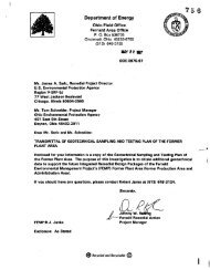
Mr. James A. Saric, Remedial Project Manager<br />
U.S. Environmental Protection Agency<br />
Region V-SRF-5J<br />
77 West Jackson Boulevard<br />
Chicago, Illinois 60604-3590<br />
Mr. Tom Schneider, Project Manager<br />
Ohio Environmental Protection Agency<br />
401 East 5th Street<br />
Dayton, Ohio 45402-291 1<br />
Dear Mr. Saric and Mr. Schneider:<br />
<strong>Department</strong> <strong>of</strong> <strong>Energy</strong><br />
Ohio Field <strong>Office</strong><br />
Fernald Area Off ice<br />
P. 0. Box 538705<br />
Cincinnati, Ohio 45253-8705<br />
(51 3) 648-31 55<br />
W R O S 898<br />
DOE-047 1-98<br />
TRANSMITTAL OF DRAFT REMEDIAL DESIGN DOCUMENTS PACKAGE FOR OPERABLE<br />
UNIT 1 ,<br />
References: 1 1<br />
21<br />
Final Remedial Action Work Plan for Remedial Actions at Operable<br />
Unit 1, January 1997.<br />
Amendment to the January 1997 Final Remedial Action Work Plan for<br />
Remedial Actions at Operable Unit 1, November 1997.<br />
In accordance with Lre approved Remedial Action Work Plan (RAWP) for Operable Unit 1<br />
(OU1) and its Amendment, this letter transmits the Remedial Design (RD) Documents<br />
Package, developed by International Technology (IT) Corporation, for review and approval.<br />
This submittal contains the following five documents identified in the approved RAWP for<br />
ou1:<br />
0 Design Package, including:<br />
0<br />
- Plant Facilities Engineering Package,<br />
Excavation Plan,<br />
- Pre-Operational Schedule;<br />
Pre-Operational Health & Safety Plan;<br />
@ RecycledandRecyckable @ 000002
e Pre-Operational Environmental Control Plan;<br />
e Site Preparation Package; and,<br />
e Operation & Maintenance Plan for Existing Facilities.<br />
Page 2<br />
A summary description <strong>of</strong> the contents <strong>of</strong> each <strong>of</strong> these elements is provided in Volume 1<br />
<strong>of</strong> the Package.<br />
The Package is being submitted approximately five weeks in advance <strong>of</strong> the April 9, 1998,<br />
regulatory milestone. This early action is being taken In order to accelerate, if possible, the<br />
date when construction can begin on the remedial facilities presented in the Design<br />
Package. We believe that we can work in concert with your agency closing out comments<br />
and securing, with sufficient confidence, an approved design. By obtaining agency<br />
commentary about five weeks early, we then will have a reasonable opportunity to advance<br />
the construction start date.<br />
Some aspects <strong>of</strong> the design are subject to ongoing consideration, but do not affect the<br />
overall scheme <strong>of</strong> the design, e.g., recent developments in fugitive dust control and<br />
stockpiling other FEMP project soils are being contractually dfscussed with IT; the water<br />
management strategy utilizes Pit 5 and the Clearwell and interaction with the bio-surge<br />
lagoon; and, the air pollution control system design is being modeled and evaluated. The<br />
DOE would like to schedule a meeting with the U.S. EPA and OEPA within about four weeks<br />
from your receipt <strong>of</strong> the subject RD Package to discuss the design and answer any<br />
questions that you may have based on your initial review <strong>of</strong> these documents.<br />
We advised your agency on February 26, 1998, (reference memorandum DOE-0404981, the<br />
OU1 remedlation may be impacted by a lawsuit filed by Waste Control Specialist and a<br />
resulting legal injunction effectively precluding the DOE from contracdng for commercial low<br />
level waste disposal. Due to this situation, it is possible that various elements <strong>of</strong> this<br />
Design Package could be affected requiring later revision. We continue to monitor<br />
developments in this ongoing case and we will maintain communications with your agency<br />
on this matter.<br />
If you have any questions or comments, or to schedule a time to discuss this package,<br />
please contact Dave Lojek at (513) 648-3127.<br />
FEMP:Lojek<br />
Enclosure: As Stated<br />
Sincerely4<br />
$.G-o-<br />
ohnny W. Reising<br />
Fernald Remedial Action<br />
Project Manager<br />
<strong>1321</strong><br />
000003
cc wlenc:<br />
S. Fauver, EM-421GTN<br />
G. Jablonowski, USEPA-V, SHRE-8J<br />
R. Beaumler, TPSSIDERR, OEPA-Columbus<br />
F. Bell, ATSDR<br />
M. Schupe, HSI GeoTrans<br />
R. Vandegrift, ODH<br />
F. Barker, Tetra Tech<br />
AR Coordinator, FDF/78<br />
cc wlo enc:<br />
D. Carr, FDF152-2<br />
R. Fellman, FDF152-1<br />
T. Hagen, FDF165-2<br />
J. Harmon, FDF190<br />
EDC, FDF152-7<br />
c<br />
c<br />
b <strong>1321</strong><br />
Page 3<br />
000004
Plant Facilities<br />
Engineering<br />
Package<br />
Waste Pit Remedial Action Project (WPW)<br />
Remedial Design Package Contents<br />
Description <strong>of</strong><br />
Operation a d Processes I<br />
Design Criteria and<br />
Assumptions<br />
Process Flow Diagrams<br />
(PFDs) w/Mass and<br />
<strong>Energy</strong> Balances<br />
Site Plans<br />
General Arrangement<br />
Plans<br />
Equipment Data Sheets<br />
/ Specifications<br />
Utility Plans for<br />
Portable Structures<br />
Point Source Emission<br />
KN/3957~RAPlEl/CO~.BN19/98(4:25 PMYfcb<br />
(Page 1 <strong>of</strong> 2)<br />
Contains facility process and control descriptions<br />
for waste preparation, drying, blending, loadout, air<br />
emissions control, water management<br />
Description <strong>of</strong> the criteria which effect the facility<br />
design including DOE orders, engineering<br />
standards and performance requirements<br />
Contains process flow diagrams for the facility.<br />
Dryer process conditions are for the average waste<br />
pr<strong>of</strong>ile.<br />
Plan view drawings <strong>of</strong> the overall facility layout<br />
Drawings <strong>of</strong> the facility equipment and building<br />
configuration with plan and elevation views<br />
Description <strong>of</strong> the process duty / pexformance<br />
requirements <strong>of</strong> the individual facility equipment<br />
items<br />
Utility routing drawings for the facility<br />
Estimate <strong>of</strong> air emissions fiom both point and<br />
Data funitive sources<br />
000005
a Waste Pit Remedial Action Project (WPRAP)<br />
Remedial Design Package Contents<br />
IO<br />
Excavation Plan<br />
Pre-Operational<br />
Description <strong>of</strong> Site<br />
Preparation Activities<br />
Site Plan<br />
Grading Plan<br />
Associated Pr<strong>of</strong>iles and<br />
Details<br />
Specifications<br />
Manufacturers '<br />
Fabrication Drawings <strong>of</strong><br />
Portable Structures<br />
Pre-Opeational<br />
Environmental Control<br />
Plan<br />
Operation and<br />
Maintenance Plan for<br />
Existing Facilities<br />
Pre-Operational Health<br />
and Safety Plan<br />
(Page 2 <strong>of</strong> 2)<br />
Description <strong>of</strong> the waste pit excavation activities<br />
Detailed schedule <strong>of</strong> activities through facility<br />
S-P<br />
~ ~~<br />
Presents the content; <strong>of</strong>the site Preparation<br />
Package and their inter-relationships.<br />
Plan view drawings <strong>of</strong> the overall facility layout<br />
Site grading plan drawing<br />
Grading pr<strong>of</strong>ile and detail drawings<br />
Civil construction specifications<br />
General floor plan, skirting, and anchoring details<br />
for trailers<br />
Description <strong>of</strong> methods and materials to be used<br />
during construction to control erosion, dust and<br />
stormwater<br />
Description <strong>of</strong> the inspection and maintenance<br />
activities to be performed prior to facility operation<br />
Project specific health and safety plan to be used<br />
during construction and mior to facility oDeration<br />
000006
DRAFT<br />
Waste Pits Remedial Action Project<br />
(WPRAP)<br />
Overview <strong>of</strong> Remedial Design Package<br />
**+<br />
PREPARED<br />
for<br />
Fluor Daniel Fernald, Inc.<br />
Fernald, Ohio<br />
FDF Subcontract No. 98SC000001<br />
***<br />
PREPARED<br />
by<br />
IT Corporation<br />
2790 Mosside Boulevard<br />
Monroeville, PA 15146-2790<br />
IT Project No. 773481<br />
***<br />
Revision B<br />
Issue Date: February 13,1998<br />
000007<br />
<strong>1321</strong>
FDF Subcontract No. 98SC000001<br />
IT Project No. 773481<br />
Record <strong>of</strong> Issue/Revisions<br />
Date<br />
1-9-98<br />
2-13-98<br />
Rev. No.<br />
A<br />
B<br />
Remedial Design Package<br />
Issue Date 2/13/98 Rev. B<br />
Description <strong>of</strong> IssudRevision<br />
Initial issue for review and comment -<br />
draft<br />
Draft Issue for EPA Review<br />
000008
FDF Subcontract No . 98SC000001<br />
IT Project No . 773481<br />
Table <strong>of</strong> Contents<br />
Remedial Design Package<br />
Issue Date: 211 3/98 Rev . B<br />
1.0 PURPOSE OF DOCUMENTS ............................................. 1<br />
2.0 PROJECT BACKGROUND ................................................ 1<br />
2.1 Site Location and Description ......................................... 1<br />
2.2 Remediationstrategy ............................................... 1<br />
3.0 GENERAL STRUCTURE OF REMEDIATION DESIGN PACKAGES ............ 2<br />
4.0 VOLUME 1 . REMEDIAL DESIGN PACKAGE CONTENTS ................... 2<br />
4.1 Plant Facilities Engineering Package .................................. -2<br />
4.1.1 Description <strong>of</strong> the Operation and Processes ....................... 2<br />
4.1.2 Design Criteria and Assumptions ............................... 2<br />
4.1.3 Process Flow Diagrams with Mass and <strong>Energy</strong> Balances ............. 3<br />
4.1.4 Site Plans .................................................. 3<br />
4.1.5 General Arrangement Plans .................................... 3<br />
4.1.6 Equipment Data Sheets and Specifications ........................ 3<br />
4.1.7 Utility Plans for Portable Structures ............................. 3<br />
4.1.8 Point Source Emissions Data ................................... 3<br />
5.0 VOLUME 2 . REMEDIAL DESIGN PACKAGE CONTENTS ................... 3<br />
5.1 Excavationplan ................................................... 3<br />
5.2 Pre-Operational Schedule ........................................... 4<br />
6.0 VOLUME 3 . REMEDIAL DESIGN PACKAGE CONTENTS ................... 5<br />
6.1 Site Preparation Package ............................................ 5<br />
6.1.1 Description <strong>of</strong> Preparation Activities ............................. 5<br />
6.1.2 SitePlan ................................................... 5<br />
6.1.3 Underground Utility Plan ...................................... 5<br />
6.1.4 Grading Plan ............................................... 5<br />
6.1.5 Associated Pr<strong>of</strong>iles and Details ................................. 5<br />
6.2<br />
6.3<br />
6.1.6 Specifications ............................................... 5<br />
6.1.7 Mandwturers Fabrication Drawings <strong>of</strong> Portable Structures ........... 5<br />
Pre-Operational Environmental Control Plan ............................ 5<br />
Operation and Maintenance Plan for Existing Facilities .................... 5<br />
6.4 Pre-Operational Hdth and Safety Plan ................................ 6<br />
7.0 REFERENCES ......................................................... 6<br />
KN/3957/WPRAelEl.Bl02-19-98(4:41 myw/NE ii<br />
000009
a<br />
e<br />
a<br />
FDF Subcontract No. 98SC000001 Remedial D&n Pac La21<br />
IT Project No. 773481<br />
Issue Date: 2/13/98 Rev. B<br />
List <strong>of</strong> AcronyrndAbbreviations<br />
AASHTO<br />
ABMA<br />
ACGIH<br />
ACI<br />
ACM<br />
ACOE<br />
AFBMA<br />
AGMA<br />
AISC<br />
ALARA<br />
ALTER<br />
AMCA<br />
ANS<br />
ANSI<br />
APC<br />
API<br />
ARAR<br />
ARI<br />
ASCE<br />
ASHRAE<br />
ASME<br />
ASNT<br />
ASTM<br />
AWS<br />
AWWA<br />
AWWT<br />
BAT<br />
BSL<br />
CAM<br />
CBR<br />
CDF<br />
CEM<br />
American Association <strong>of</strong> State Highway Transportation Officials<br />
American Bearing Manufhcturers Association<br />
American Conference <strong>of</strong> Government Industrial Hygienists<br />
American Concrete Institute<br />
Asbestos Containing Material<br />
United States Army Corps <strong>of</strong> Engineers<br />
Anti-Friction Bearing Manufacturers Assocktion<br />
American Gear Manufkcturers Association<br />
American Institute <strong>of</strong> Steel Construction<br />
As Low As Reasonably Achievable<br />
Accelerated Life Testing and Environmental Research Facility<br />
Air Movement and Control Association<br />
American Nuclear Society<br />
American National Standards Institute<br />
Air Pollution Control<br />
American Petroleum Institute<br />
Applicable or Relevant and Appropriate Requirement.<br />
American Refiigeration Institute<br />
American Society <strong>of</strong> Civil Engineers<br />
American Society <strong>of</strong> Heating, Refrigeration and Air Conditioning Engineers<br />
American Society <strong>of</strong> Mechanical Engineers<br />
American Society <strong>of</strong> Nondestructive Testing<br />
American Society for Testing and Materials<br />
American Welding Society<br />
American Water Works Association<br />
Advanced Wastewater Treatment<br />
Best Available Technology<br />
Biodenitrification Surge Lagoon<br />
Continuous Air Monitor<br />
California Bearing Ratio<br />
Commercial Disposal Facility<br />
Continuous Emissions Monitor<br />
000010
FDF Subcontract No. 98SC000001<br />
IT Project No. 773481<br />
List <strong>of</strong> Acronyms and Abbreviations (Continued)<br />
CEMA<br />
CERCLA<br />
CFR<br />
COC<br />
CPT<br />
CRSI<br />
CRU<br />
CWA<br />
D&D<br />
DAC<br />
DCD<br />
DEEP<br />
DOE<br />
DOE-NV<br />
DOT<br />
EJMA<br />
ERDA<br />
F<br />
FDF<br />
FEMP<br />
FERMCO<br />
FFCA<br />
@m<br />
FS<br />
FSAR<br />
ft2<br />
GCS<br />
GFCI<br />
GLC<br />
gPm<br />
HEPA<br />
hr<br />
WAC<br />
Remedial Design Package<br />
Issue Date: 2/13/98 Rev. B<br />
Conveyor Equipment Manufacturers Association<br />
Comprehensive, Environmental Response, Compensation, and Liability Act<br />
Code <strong>of</strong> Federal Regulations<br />
Constituent <strong>of</strong> Concern<br />
Cone Penetrometer Test<br />
Concrete Reinforcing Steel Institute<br />
CERCLARCRA Unit<br />
Clean Water Act <strong>of</strong> 1977, as amended<br />
Decontamination and Dismantlement<br />
Derived Air Concentration<br />
Design Criteria Document<br />
Dewatering Excavation Evaluation Program<br />
United States <strong>Department</strong> <strong>of</strong> <strong>Energy</strong><br />
United States <strong>Department</strong> <strong>of</strong> <strong>Energy</strong> - Nevada <strong>Office</strong> <strong>of</strong> Operations<br />
United States <strong>Department</strong> <strong>of</strong> Transportation<br />
Expansion Joint Man~dbctwers Association<br />
<strong>Energy</strong> Research and Development Administration<br />
Fahrenheit<br />
Fluor Daniel Fernald, Inc.<br />
Fernald Environmental <strong>Management</strong> Project<br />
Fernald Environmental Restoration <strong>Management</strong> Corporation<br />
Federal Facilities Compliance Agreement<br />
feet per minute<br />
Feasibility Study<br />
Final Safety Analysis Report<br />
square foot (feet)<br />
Gas Cleaning System<br />
Ground Fault Circuit Interrupter<br />
Ground Level Concentration<br />
gallons per minute<br />
High Efficiency Particulate Air (filter)<br />
hour<br />
Heating, Ventilation, and Air Conditioning<br />
Mn957NPRAPIElg/o2-19-98(441 pywINE iv<br />
000011
v-<br />
FDF Subcontract No. 98SC000001<br />
IT Project No. 773481<br />
List <strong>of</strong> Acronyms and Abbreviations (Continued)<br />
IEEE<br />
IES<br />
ID<br />
IPC<br />
ISA<br />
IT<br />
kg<br />
kV<br />
kVA<br />
kW<br />
lb<br />
LLRW<br />
m2<br />
MAGLC .<br />
MAWC<br />
MBMA<br />
MCC<br />
ME1<br />
MHB<br />
pci/cc<br />
mrem<br />
MSS<br />
NAD<br />
NEC<br />
NEMA<br />
NESW<br />
NETA<br />
NFC<br />
NFPA<br />
NP<br />
NPDES<br />
NPH<br />
NTS<br />
7<br />
Institute <strong>of</strong> Electrical and Electronics Engineers<br />
Illuminating Engineers Society<br />
Induced Draft<br />
Inclined Plate Clarifier<br />
International Society for Measurement and Control<br />
IT Corporation<br />
kilogram<br />
kilovolt<br />
kilivolt-ampere<br />
kilowatt<br />
pound<br />
Low Level Radioactive Wastes<br />
square meter<br />
Maximum Allowable Ground Level Concentration<br />
Maximum Average Waste Concentration<br />
Metal Building Manufhcturers Association<br />
Motor Control Center<br />
Maximally Exposed Individual<br />
Material Handling Building<br />
microcurie per cubic centimeter<br />
millirem<br />
Manuf'acturers Standardization Society<br />
North American Datum<br />
National Electric Code<br />
National Electrical Manufbcturers Association<br />
National Emission Standards for Hazardous Air Pollutants<br />
National Electrical Testing Association<br />
National Fuel Code<br />
National Fire Protection Association<br />
Nonplastic<br />
National Pollutant Discharge Elimination System<br />
Natural Phenomenal Hazard<br />
Nevada Test Site<br />
M3957i7/wpRAp/EI .B/O2-19-98(441 ~yDoINE V<br />
1<br />
it. *- 1-32<br />
Remedial Design Package<br />
Issue Date: 2/13/98 Rev. B<br />
000012
FDF Subcontract No. 98SCOOOOO 1<br />
IT Project No. 773481<br />
List <strong>of</strong> Acronyms and Abbreviations (Continued)<br />
OAC<br />
OBBC<br />
ODOT<br />
Ohio<br />
OSDF<br />
OSHA<br />
ou<br />
PC<br />
PCB<br />
pcf<br />
pci/L<br />
PFD<br />
PID<br />
PPE<br />
PSf<br />
psi<br />
PTI<br />
PTO<br />
PVC<br />
QAP<br />
RCRA<br />
RD<br />
RI<br />
lUB<br />
ROD<br />
SAE<br />
scs<br />
SDI<br />
sec<br />
SJI<br />
SMACNA<br />
SPT<br />
ssc<br />
Ohio Administrative Code<br />
Ohio Basic Building Code<br />
Ohio <strong>Department</strong> <strong>of</strong> Transportation<br />
EPA Ohio Environmental Protection Agency<br />
On Site Disposal Facility<br />
Occupational Safety and Health Administration<br />
Operable Unit<br />
Performance Category<br />
Polychlorinated Biphenyl<br />
pounds per cubic foot<br />
picoCuries per liter<br />
Process Flow Diagram<br />
Photoionizing Detector<br />
Personal Protective Equipment<br />
pounds per square foot<br />
pounds per square inch<br />
Permit to Install<br />
Permit to Operate<br />
Polyvinyl Chloride<br />
Quality Assurance Plan<br />
Resource Conservation 'and Recovery Act<br />
Remedial Design<br />
Remedial Investigation<br />
Railcar Loadout Building<br />
Record <strong>of</strong> Decision<br />
Society <strong>of</strong> Automotive Engineers<br />
Soil Conservation Service<br />
Steel Deck Institute<br />
second<br />
Steel Joist Institute<br />
Sheet Metal and Air Conditioning Contnrctors National Association<br />
Standard Penetration Test<br />
Structure, System and Component<br />
Remedial Design Package<br />
Issue Date: 2/13/98 Rev. B<br />
000013
FDF Subcontract No. 98SC000001<br />
IT Project No. 773481<br />
List <strong>of</strong> Acronyms and Abbreviations (Continued)<br />
STD<br />
SWM<br />
SWPPP<br />
TBC<br />
TBP<br />
TEMA<br />
TOC<br />
TSDF<br />
UBC<br />
UCRL<br />
UL<br />
USCS<br />
USEPA<br />
V<br />
WAC<br />
WESP<br />
WPM<br />
. WTS<br />
Yd3<br />
Yr<br />
Standard (DOE)<br />
Solid Waste <strong>Management</strong><br />
FERMCO Storm Water Pollution Prevention Plan<br />
To Be Considered<br />
Tributyl Phosphate<br />
Tubular Exchanger Manufhcturers Association<br />
Total Organic Carbon<br />
Waste Treatment, Storage or Disposal Facility<br />
Uniform Building Code<br />
University <strong>of</strong> California Research Laboratory<br />
Underwriters Laboratory<br />
Unified Soil Classification System<br />
United States Environmental Protection Agency @PA)<br />
Volt<br />
Waste Acceptance Criteria<br />
Wet Electrostatic Precipitator<br />
Waste Pits Remedial Action Project<br />
IT Corporation Wastewater Treatment System<br />
cubic yard<br />
Year<br />
KN/3957MfpRApIEI.B/Q2-1948(441 wywME vii<br />
Remedial Design Package<br />
Issue Date: 2/13/98 Rev. B<br />
000014
FDF Subcontract No. 98SC000001<br />
IT Project No. 773481<br />
- <strong>1321</strong><br />
Remedial Design Package<br />
Issue Date: 2/13/98 Rev. B<br />
1.0 PURPOSE OF DOCUMENTS 1<br />
The design documents contained in this Remedial Design Package are submitted for review by 2<br />
the United States Environmental Protection Agency (US EPA)/Ohio Environmental Protection 3<br />
Agency (Ohio EPA) for the Fernald Waste Pits Remedial Action Project (WPRAP) remediation 4<br />
<strong>of</strong> the Fernald Environmental <strong>Management</strong> Project (FEMP) operable Unit 1 (OU1) waste pits. 5<br />
2.0 PROJECT BACKGROUND<br />
2.1 Site Location and Description<br />
The FEMP is a 1 O50-acrey government owned facility located approximately 18 miles northwest<br />
<strong>of</strong> the city <strong>of</strong> Cincinnati, Ohio. It is situated on the boundary between Hamilton and Butler<br />
Counties. The FEMP, which operated under the name <strong>of</strong> the Feed Materials Production Center,<br />
produced high purity uranium metal products for the United States <strong>Department</strong> <strong>of</strong> <strong>Energy</strong> (DOE)<br />
and its predecessor agencies fiom 1952 to 1989. Former uranium processing operations at the<br />
FEMP were limited to a fenced, 136-acre tract, closed to public access, known as the production<br />
area. In June 199 1 , the site was <strong>of</strong>ficially closed for production by an act <strong>of</strong> Congress. The<br />
Fernald site was included on the Comprehensive Environmental Response, Compensation, and<br />
Liability Act National Priorities List in 1989. The current mission <strong>of</strong> the site is the safe<br />
environmental restoration <strong>of</strong> the site in accordance with all applicable requirements.<br />
OU1 is a well-defined, 37.7-acre area located in the northwest quadrant <strong>of</strong> the FEW site. Large<br />
quantities <strong>of</strong> liquid and solid wastes that were generated by various chemical and metallurgical<br />
processing operations were stored or disposed in the six waste pits and the Clearwell, or burned<br />
in the Burn Pit. These waste pits are located in a portion <strong>of</strong> the FEMP Waste Storage Area and<br />
are contained within the boundaries <strong>of</strong> OU1. A detailed discussion <strong>of</strong> each waste pit’s<br />
construction, contents, and volume <strong>of</strong> waste material is provided in the Remedial Investigation<br />
Report for Operable Unit 1 (DOE 1994).<br />
2.2 Remediation Strategy<br />
Remediation <strong>of</strong> OU1 is based on the final Record <strong>of</strong> Decision (ROD) for Remedial Action at<br />
Operable Unit 1 (DOE 1995a), signed by the US EPA on March 1 , 1995. The overall goal <strong>of</strong> the<br />
Waste Pits Remedial Action Project (WPRAP) (the area known as OU1) is to remediate all the<br />
OU1 components in a timely, efficient, and cost-effective manner, ensuring compliance with all<br />
Applicable or Relevant and Appropriate Requirements (ARARs), and promting human he&h<br />
and the environment. The selected remedy presented in the OU1 ROD is excavation <strong>of</strong> the waste<br />
1<br />
000015<br />
6<br />
7<br />
8<br />
9<br />
10<br />
11<br />
12<br />
13<br />
14<br />
15<br />
16<br />
17<br />
18<br />
19<br />
20<br />
21<br />
22<br />
23<br />
24<br />
25<br />
26<br />
27<br />
28<br />
29<br />
30<br />
31<br />
32<br />
33<br />
34<br />
35
FDF Subconeact No. 98SC000001<br />
IT Project No. 773481<br />
-<br />
Rantdial Design Package<br />
Issue Date: 2/13/98 Rev. B<br />
pit contents, waste processing and treatment by thermal drying (as necessary to remove flee<br />
water), and <strong>of</strong>f-site disposal at a Commercial Disposal Facility (CDF).<br />
3.0 GENERAL STRUCTURE OF REMEDIATION DESIGN PACKAGES<br />
This submittal consists <strong>of</strong> several design documents which have been compiled into three<br />
separate volumes. The information is divided as follows:<br />
0 Volume 1 addresses the equipment and facilities directly associated with the<br />
processing <strong>of</strong> waste.<br />
Volume 2 addresses the waste excavation plan and pre-operational schedule.<br />
0 Volume 3 addresses the site preparation package and the project preoperational plans<br />
to support the construction and other pre-operation activities <strong>of</strong> the waste processing<br />
facility.<br />
To the extent possible, various documents reference each other rather than repeat detailed<br />
information.<br />
4.0 VOLUME 1 - REMEDIAL DESIGN PACKAGE CONTENTS<br />
4.1 Plant Facilities Engineering Package<br />
4.1.1 Description <strong>of</strong> the Operation and Processes<br />
This document provides a description <strong>of</strong> the WRAP operation and processes including the<br />
sequence and operating parameters associated with waste preparation; material handling;<br />
wastewater and storm water treatment, control, and distribution; process surge capacity and<br />
configuration; blending; drying; air emissions controls (hitive and point source); sampling and<br />
analysis; loadout; and process control philosophy. Also discussed are the rationale for selecting<br />
the process sequence and utility requirements.<br />
4.1.2 Design Criteria and Assumptions<br />
This document provides a description <strong>of</strong> the specific criteria which &ect the WRAP design<br />
including performance requirements, applicable DOE orders, and standard industrial codes. The<br />
design criteria also covers the compliance strategy for ARARs and substantive permit<br />
requirements. A permitting crosswalk is presented including a description <strong>of</strong> where in the design<br />
package a particular requirement is addressed. The design criteria also summarizes the results <strong>of</strong><br />
KN/39S7/WPRAP/El .B/M-19-98(4:41 payDoINE 2<br />
<strong>1321</strong><br />
1<br />
2<br />
3<br />
4<br />
5<br />
6<br />
7<br />
8<br />
9<br />
10<br />
11<br />
12<br />
13<br />
14<br />
15<br />
16<br />
17<br />
18<br />
19<br />
20<br />
21<br />
22<br />
23<br />
24<br />
25<br />
26<br />
27<br />
28<br />
29<br />
30<br />
31 .<br />
32<br />
33<br />
34<br />
35<br />
36<br />
37<br />
000016
@<br />
FDF Subcontract No. 98SC000001<br />
IT Project No. 773481<br />
Remedial Design Package<br />
Issue Date: 2/13/98 Rev. B<br />
studies and evaluations made in support <strong>of</strong> the design. Assumptions are stated for any design<br />
criteria which can not be verified until field work begins.<br />
4.1.3 Process Flow Diagrams with Maas and <strong>Energy</strong> Balances<br />
Contains the Process Flow Diagrams (PFDs) for the facility processes including waste<br />
preparation, drying and <strong>of</strong>f-gas treatment, dried waste loadout and blending, wastewater<br />
treatment, and overall water balance.<br />
4.1.4 Site Plans<br />
A plan view drawing <strong>of</strong> the overall WRAP facility layout is given in this section.<br />
4.1.5 General Arrangement Plans<br />
Drawings <strong>of</strong> the equipment and building configurations are given in this section in both plan and<br />
elevation views. The waste preparation and blending area, drying and <strong>of</strong>f-gas treatment area, rail<br />
car loadout area, and wastewater treatment area are included in the views.<br />
4.1.6 Equipment Data Sheets and Specifications<br />
A description <strong>of</strong> the process duty andor general specification for major process equipment items<br />
is given in this section. This includes the material handling equipment, dryer and <strong>of</strong>f-gas<br />
treatment system, and wastewater treatment equipment.<br />
4.1.7 Utility Plans for Portable Structures<br />
Drawings <strong>of</strong> the utility routing to the facility portable structures (trailers) is given in this section.<br />
Utilities for both the process and administration area structures are included.<br />
4.1.8 Point Source Emissions Data<br />
Estimate <strong>of</strong> the air emissions from the dryer and <strong>of</strong>f-gas treatment system. Also included are<br />
fugitive emission estimates from the Material Handling Building, and Railcar Loadout Building.<br />
5.0 VOLUME 2 - REMEDIAL DESIGN PACKAGE CONTENTS<br />
5.1 Excavation Plan 32<br />
Provides a description <strong>of</strong> the processes used to transfer material fiom the waste pit area to the 33<br />
waste processing facility. The document also includes the following:<br />
KNn957/wpRAp/EI.B/oz-l9-98(441 pnyDoINE 3<br />
1<br />
2<br />
3<br />
4<br />
5<br />
6<br />
7<br />
8<br />
9<br />
10<br />
11<br />
12<br />
13<br />
14<br />
15<br />
16<br />
17<br />
18<br />
19<br />
20<br />
21<br />
22<br />
23<br />
24<br />
25<br />
26<br />
27<br />
28<br />
29<br />
30<br />
31<br />
34<br />
35
- <strong>1321</strong><br />
Rcmcdiakgn Package<br />
FDF Subcontract No. 98SC000001<br />
IT Project No. 773481 Issue Date: 213198 Rw.B<br />
\<br />
e<br />
e<br />
e<br />
e<br />
e<br />
e<br />
e<br />
e<br />
e<br />
e<br />
e<br />
e<br />
e<br />
e<br />
Overall excavation sequence and method<br />
Criteria and assumptions (including slope stability and bearing capacity <strong>of</strong> the waste<br />
material)<br />
Pr<strong>of</strong>iles, sections, and details <strong>of</strong> the pits as they currently exist<br />
Material handling considerations, including considerations specific to the handling <strong>of</strong><br />
nontypical wastes<br />
Discussion <strong>of</strong> pit dewatering<br />
Leachate and storm water run-odrun<strong>of</strong>f management and approach to minimize<br />
leachate infiltration to the aquifer<br />
Excavation sequencing and processes to be used in the excavation <strong>of</strong> individual waste<br />
pits including plans and sections<br />
Manpower requirements and equipment selection for waste excavation and transport<br />
Proposed stockpile areas for potential blending and segregation<br />
Debris management and segregation<br />
Air monitoring (specific sampling and analysis details are given in the Sampling and<br />
Analysis Plan which is not part <strong>of</strong> this package)<br />
Dust and fugitive emissions controls<br />
Equipment decontamination facilities and procedures<br />
Interim and final grading.<br />
5.2 Preoperational Schedule<br />
The schedule identifies major activity elements and milestones, fiom WRAP contract award to<br />
Initiation <strong>of</strong> Operations.<br />
KN/3957/WPRAPffil .B/Q2-19-98(441 pa~ywME 4<br />
000018<br />
1<br />
2<br />
3<br />
4<br />
5<br />
6<br />
7<br />
8<br />
9<br />
10<br />
11<br />
12<br />
13<br />
14<br />
15<br />
16<br />
17<br />
18<br />
19<br />
20<br />
21<br />
22<br />
23<br />
24<br />
25<br />
26<br />
27<br />
28<br />
29<br />
30<br />
31<br />
32<br />
33<br />
34<br />
35<br />
36<br />
37
-- L. 1381.<br />
FDF Subcontract No. 98SC000001<br />
Ramdial Design Package<br />
IT hi& No. 773481 Issue Date: 2/13/98 Rw.B<br />
~~<br />
6.0 VOLUME 3 - REMEDIAL DESIGN PACKAGE CONTENTS<br />
6.1 Site Preparation Package<br />
6.1.1 Description <strong>of</strong> Preparation Activities<br />
This section presents the contents <strong>of</strong> the site preparation package and their interrelationships.<br />
6.1.2 Site Plan<br />
Drawing depicts the overall facility layout including relative location <strong>of</strong> the WRAP facility<br />
structures and equipment in relation to the waste pits and rail spurs.<br />
6.1.3 Underground Utility Plan<br />
This section contains utility routing drawings for the facility. Utilities for both the process and<br />
administration area structures are included.<br />
6.1.4 Grading Plan<br />
This section contains the soil grading plan drawing for construction <strong>of</strong> the WRAP facility.<br />
6.1.5 Associated Pr<strong>of</strong>iles and Details<br />
Contains soil grading drawings which show the sections, pr<strong>of</strong>iles and details for construction <strong>of</strong><br />
the facility.<br />
6.1.6 Specifications<br />
Contains civil construction specifications.<br />
6.1.7 Manufacturers Fabrication Drawings <strong>of</strong> Portable Structures<br />
General floor plan, skirting , and anchoring details for trailers.<br />
6.2 Preoperational Environmental Control Plan<br />
This document contains a description <strong>of</strong> the methods and materials to be used during site<br />
preparation and construction to control erosion, dust, and storm water to minimize the impact <strong>of</strong><br />
these activities upon the environment.<br />
6.3 Operation and Maintenance Plan for Existing Facilities<br />
1<br />
2<br />
3<br />
4<br />
5<br />
6<br />
7<br />
8<br />
9<br />
10<br />
11<br />
12<br />
13<br />
14<br />
15<br />
16<br />
17<br />
18<br />
19<br />
20<br />
21<br />
22<br />
23<br />
24<br />
25<br />
26<br />
27<br />
28<br />
29<br />
30<br />
31<br />
32<br />
33<br />
34
*<br />
FDF Subcontract No. 98SC000001<br />
IT Project No. 773481 Issue Date: 2/13/98 Rev.B<br />
This document contains a description <strong>of</strong> the inspection and maintenance activities to be<br />
performed in the waste pit and site improvement area prior to facility operation.<br />
6.4 Pre-Operational Health and Safety Plan 4<br />
The Pre-Operational Hdth and Safety Plan provides the methods which will be implemented to 5<br />
comply with the FEMP health and safety requirements for the safe performance <strong>of</strong> the pre- 6<br />
operational remedial activities. 7<br />
7.0 REFERENCES<br />
Accelerated Life Testing and Environmental Research Facility (ALTER), 1994, CRUl<br />
Cooperative Reme& Screening Program, Final Report, Cincinnati: University <strong>of</strong> Cincinnati,<br />
College <strong>of</strong> Engineering, July.<br />
Accelerated Life Testing and Environmental Research Facility (ALTER), 1995, Interim Report,<br />
CRU-I-Dewatering, Excavation, Evaluation Program: Was& piis I 2, and 3. Cincinnati:<br />
University <strong>of</strong> Cincinnati, College <strong>of</strong> Engineering, September.<br />
Femald Environmental <strong>Management</strong> Progect (FEMP), Stormwater Pollution Prevention Plan,<br />
RM-0039.<br />
Fernald Environmental Restoration <strong>Management</strong> Corporation (FERMCO), '1 995, <strong>Management</strong><br />
Plan: FERMCO Policies and Requirements Manual, Rev. 7, Femald: FERMCO, RM-0016,<br />
June.<br />
Ohio <strong>Department</strong> <strong>of</strong> Natural Resources (DNR), 1996, Rainwater and Land Development,<br />
Ohio's Standards for Stormwater <strong>Management</strong> Land Development and Urban Stream<br />
Protection, Second Edition, 1996.<br />
Harmer, D., IT Corporation, 1997, Calculation Bases and Methods for Uranium Enrichmed<br />
Depletion in the Fernald Operable Unit 1 Pits, June 10,1997.<br />
Jenike and Johanston, Inc., 1994, Flow Properties Test Report, Westford, MA, Jenike and<br />
Johanston, Inc. 1994.<br />
Kirk-Othmer, 1994, "Encyclopedia <strong>of</strong> Chemical Technology," Fourth Edition, Vol. 9,<br />
Elastomers, Polyisoprene to Expert Systems, published by John Wiley & Sons, New York, New<br />
York.<br />
PARSONS ERA Project, 1994, Report on Ekecution <strong>of</strong> Surrogate Waste Drying Tests,<br />
Revision A, Fairfield: August 1994.<br />
Kw3957MrpRApIEl .B1112-19-98(441 pyw/NE 6<br />
c)00020<br />
1<br />
2<br />
3<br />
8<br />
9<br />
10<br />
11<br />
12<br />
13<br />
14<br />
15<br />
16<br />
17<br />
18<br />
19<br />
20<br />
21<br />
22<br />
23<br />
24<br />
25<br />
26<br />
27<br />
28<br />
29<br />
30<br />
31<br />
32<br />
33<br />
34<br />
35<br />
36<br />
37<br />
38<br />
39<br />
40<br />
41<br />
42
= <strong>1321</strong><br />
FDF Subcontract No. 98SC000001 Rantdial.&&iPackage<br />
IT Project No. 773481 Issue Datt: 2/13/98 Rev. B<br />
a PARSONS ERA Project, 1994, Shredding Engheering Tab Report, Fairfield: PARSONS 1<br />
1994. 2<br />
3<br />
PARSONS ERA Project, 1995, Preliminary Technical Summary <strong>of</strong> DEEP Test Data, Revision<br />
A, Fairfield: PARSONS October 1995.<br />
PARSONS ERA Project, 1995, Dryer On-Gas Conpsitions, Operable Unit I Remed-n<br />
System, Revision A, Fairfield: PARSONS, September 1995.<br />
PARSONS ERA Project, 1995, Process Description for the Remediation System Design,<br />
Revision Cy Fairfield: PARSONS, October 1995.<br />
PARSONS ERA Project, 1995, Control Philosophy for the Remediation System Design,<br />
Revision Cy Fairfield: PARSONS, October 1995.<br />
PARSONS ERA Project, 1995, Preliminary Estimate <strong>of</strong> Utility Requirements for Proposed<br />
Remedial Facili&s for OUI Remediation, Revision By Fairfield: PARSONS, October 1995.<br />
PARSONS ERA Project, 1995, Description <strong>of</strong> Site Preparation Activities, and related drawings,<br />
Fairfield: PARSONS, October 1995.<br />
PARSONS ERA Project, 1995, Waste likcavation Plan for the Operable Unit 1 Remediation<br />
System Design, Fairfield: PARSONS, October 1995.<br />
U.S. <strong>Department</strong> <strong>of</strong> Commerce, 1995, “Rainfall Frequency Atlas <strong>of</strong> the U.S.”, Technical Paper<br />
40.<br />
U.S. <strong>Department</strong> <strong>of</strong> <strong>Energy</strong> (DOE), 1994, Operable Unit I Dewatering ficavation Evaluation<br />
Program (DEEP,) Treatabila Study Work Plan, Final, Fernald: DOE Fernald Field <strong>Office</strong>,<br />
DOE 1994a.<br />
U.S. <strong>Department</strong> <strong>of</strong> <strong>Energy</strong> (DOE), 1994b, Remedial Investigation Report for Operable Unit I,<br />
Final, Fernald: DOE Fernald Field <strong>Office</strong>, DOE, August 1994.<br />
US. <strong>Department</strong> <strong>of</strong> <strong>Energy</strong> (DOE), 1994, Feasibility Stud’ Report for Operable Unit 1, Final,<br />
Fernald: DOE Fernald Field <strong>Office</strong>, DOEEA-0938, October 1994.<br />
U.S. <strong>Department</strong> <strong>of</strong> <strong>Energy</strong> (DOE), 1995, Final Record <strong>of</strong> Decision for Remedial Actions at<br />
Operable Unit I, Fernald: DOE Fernald Field <strong>Office</strong>, January 1995.<br />
U.S. <strong>Department</strong> <strong>of</strong> <strong>Energy</strong> (DOE), 1995, Final Remedial Design Work Plan for Remediul<br />
Actions at Operable Unit I, Fernald: DOE Fernald Field <strong>Office</strong>, July 1995.<br />
U.S. <strong>Department</strong> <strong>of</strong> <strong>Energy</strong> (DOE), 1997, Final Remedial Action Work Plan for Remedial<br />
Actions at Operable Unit 1, Fernald, DOE FernaldArea Ome, January, 1997.<br />
7<br />
4<br />
5<br />
6<br />
7<br />
8<br />
9<br />
10<br />
11<br />
12<br />
13<br />
14<br />
15<br />
16<br />
17<br />
18<br />
19<br />
20<br />
21<br />
22<br />
23<br />
24<br />
25<br />
26<br />
27<br />
28<br />
29<br />
30<br />
31<br />
32<br />
33<br />
34<br />
35<br />
36<br />
37<br />
38<br />
39<br />
40<br />
41<br />
42<br />
43<br />
44<br />
45<br />
000021
FDF Subcontract No. 98SC000001<br />
Remedial Design<br />
IT Project No. 773481 Issue Date: 2/13/98 Rev. B<br />
J1<br />
Package <strong>1321</strong><br />
Weston, Roy F., Inc., 1988, Characterization Investigation Study Geotechnkal Evaluation <strong>of</strong> 1<br />
Wmte Pit Material Properties and Boring Logs, Cincinnati, March 1988. 2<br />
8<br />
000022<br />
3
DRAFT<br />
Waste Pits Remedial Action Project<br />
(WPRAP)<br />
Description <strong>of</strong> the Operation and Processes<br />
***<br />
PREPARED<br />
for<br />
Fluor Daniel Fernald, Inc.<br />
Fernald, Ohio<br />
FDF Subcontract No. 98SCOOOOOl<br />
***<br />
PREPARED<br />
bY<br />
IT Corporation<br />
2790 Mosside Boulevard<br />
Monroeville, PA 15146-2790<br />
IT Project No. 773481<br />
***<br />
--<br />
Revision B<br />
Issue Date: February 13, 1998<br />
c<br />
I<br />
b <strong>1321</strong>
FDF Subcontract No. 98SCOoooO1<br />
IT Project No. 773481<br />
Record <strong>of</strong> IssudRevisions<br />
Date<br />
1-9-98<br />
2-13-98<br />
Rev. No.<br />
A<br />
B<br />
Description <strong>of</strong> opaation & Process<br />
IssueDate: 2/13/98 Rev. B<br />
Description <strong>of</strong> Revision<br />
Original Issue <strong>of</strong> Draft<br />
Draft Issue for EPA Review
m<br />
FDF Subcontract No . 98SCOOOOO1<br />
IT Project No . 773481<br />
Table <strong>of</strong> Confents<br />
Description <strong>of</strong> Operation & Process<br />
Issue Date: 2/13/98 Rev . B<br />
..................................................................<br />
.................................................<br />
.......................................................<br />
................................................<br />
...................................................<br />
.....................................................<br />
List <strong>of</strong> Tables v<br />
List <strong>of</strong> AcronymdAbbreviations vi<br />
1.0 INTRODUCTION 1<br />
2.0 PROCESS DESCRIPTION 1<br />
2.1 WasteExcavation 1<br />
2.2 Waste Blending 2<br />
2.3 Waste Preparation (PFD D-15-10-001) ................................... 4<br />
2.3.1 Initial Waste Classification 4<br />
2.4<br />
2.5<br />
2.6<br />
2.7<br />
2.8<br />
......................................<br />
...............................................<br />
....................................................<br />
2.3.2 Initial Blending 5<br />
2.3.3 Screening 5<br />
2.3.4 Shredding .................................................... 6<br />
2.3.5 Dust Control 6<br />
.................................................<br />
..............................................<br />
................................................<br />
2.3.6 Waste Processing 7<br />
2.3.7 Final Blending 7<br />
Dryer Feed System (PFD D- 10- 10-00 1) .................................. 7<br />
Thermal Dryer Operation (PFD D-20-10-001) ............................. 8<br />
Gas Cleaning System (PFD D-50-10-001) ................................ 9<br />
Railcar Loadout and Lidding (PFD D-35-10-001) ......................... 12<br />
2.7.1 Railcar Loadout and Lidding Operations .......................... 13<br />
2.7.2 Railcar Rejection at the CDF .................................... 14<br />
Water <strong>Management</strong> (PFDs M-65- 10-001 and M-90- 10-00 1) ................. 15<br />
2.8.1 Process Wastewater ...........................................<br />
2.8.1.1 Cooling Tower Blowdown Water ........................<br />
17<br />
17<br />
2.8.1.2 OiVWater Separator Discharge .......................... 17<br />
2.8.1.3 BackwashRecycle Water from the WTS .................. 17<br />
2.8.2 Nonprocess Wastewater and Contact Storm Water ................... 18<br />
2.8.2.1 Laundry Water 18<br />
KNl3957/wpruPlEuE2.W-22-98( 100 1 a~nyDl /NE<br />
.......................................<br />
2.8.2.2 Respirator Wash Water ................................ 18<br />
2.8.2.3 Changeout Facility Shower Water ........................ 19<br />
2.8.2.4 Grey Water Collection Tank ............................ 19<br />
2.8.2.5<br />
2.8.2.6<br />
Laboratory Wastewater ................................ 19<br />
Material Handling Building Collection Sumps .............. 19<br />
2.8.2.7 Railcar Loadout Building Decontamination Sumps .......... 20<br />
..<br />
11<br />
000025
w<br />
FDF Subcontract No . 98SC000001<br />
IT Project No . 77348 1<br />
Table <strong>of</strong> Contents (Continued)<br />
3.0<br />
2.9<br />
Description <strong>of</strong> operation & Process<br />
Issue Date: 2/13/98 Rev . B<br />
2.8.2.8 Dryer Enclosure Collection Sump ........................ 20<br />
2.8.2.9 Material Handling Building Collection Tank ............... 20<br />
2.8.2.10 Truck Turnaround Area Collection Sump .................. 20<br />
2.8.2.1 1 Truck Wash Collection Sump ........................... 21<br />
2.8.2.12 Decontamination Pad Wastewater ........................ 21<br />
2.8.2.13 Contact Storm Water Collected at the WTS ................ 21<br />
2.8.3 Noncontact Storm Water Outside the Pit Area ...................... 21<br />
2.8.4 Contact Storm Water and Excavation Water from the Waste Pit Area .... 22<br />
2.8.4.1 Contact Storm Water from Waste Pit 6 .................... 23<br />
2.8.4.2 Contact Storm Water fkom Waste Pit 5 .................... 24<br />
2.8.4.3 Excavation Water ..................................... 24<br />
2.8.4.4 Contact Storm Water fiom Haul Roads in the Waste Pit Area . . 25<br />
2.8.5<br />
2.8.4.5 Contact Storm Water in the Clearwell and Surrounding Areas . . 25<br />
Noncontact Storm Water Inside the Pit Area ....................... 26<br />
2.8.5.1 Noncontact Storm Water from Waste Pits 1,2, and 3 ......... 26<br />
2.8.5.2<br />
2.8.5.3<br />
Noncontact Storm Water fiom Waste Pit 4 ................. 26<br />
Noncontact Storm Water from Areas Bordering the Waste Pits . 27<br />
Water Treatment System (PFD M-65- 10-00 1) ............................ 27<br />
2.9.1 Solids Setting and Equalization .................................. 27<br />
2.9.2 Initial pH Adjustment ......................................... 28<br />
2.9.3 Clarification ................................................. 28<br />
2.9.4 Sand Filtration ............................................... 29<br />
2.9.5 Ion Exchange ................................................ 29<br />
2.9.6 Final pH Adjustment .......................................... 29<br />
2.9.7 Effluent DischargeRecycle ..................................... 29<br />
PROCESS CONTROL PHILOSOPHY ...................................... 30<br />
3.1 Waste Removal, Blending, and Preparation .............................. 30<br />
3.2 Dryer Feed System (PFD D- 10- 1 0-00 1) .................................. 31<br />
3.3<br />
3.2.1 Operations .................................................. 31<br />
3.2.2 Instrumentation and Controls ................................... 32<br />
Thermal Dryer Operation (PFD D-20-10-001) ............................ 33<br />
3.3.1 Operations .................................................. 33<br />
3.3.2 Instrumentation and Controls ................................... 34<br />
KN/3957MrpIuP/Eun.W2-22-98( 1O:O 1 atnyDIINE iii
FDF Subcontract No . 98SCOooOO 1<br />
IT Project No . 77348 1<br />
Table <strong>of</strong> Contents (Continued)<br />
. Description <strong>of</strong> Operation-& Process<br />
Issue Date: 2/13/98 Rev . B<br />
3.4 Gas Cleaning System (PFD D-50-10-001) ............................... 35<br />
3.4.1 Operations .................................................. 35<br />
3.5<br />
3.6<br />
3.4.2 Instrumentation and Controls ................................... 37<br />
Railcar Loadout and Lidding Operations (PFD D-35-10-001) ................ 38<br />
Water Treatment System ............................................. 38<br />
I 4.0 SAMPLING AND ANALYSIS ............................................ 39<br />
4.1 Sampling ......................................................... 40<br />
4.2 Analyses ......................................................... 40<br />
5.0 UTILITY REQUIREMENTS .............................................. 43<br />
5.1 Electricity ........................................................ 44<br />
5.2 Caustic ........................................................... 44<br />
5.3 NaturalGas ....................................................... 45<br />
5.4 Fuel Oil .......................................................... 45<br />
5.5 Compressed Air (Plant and Instrument) ................................. 45<br />
5.6 Water (Potable and Process) .......................................... 46<br />
5.7 Fire Water ........................................................ 46<br />
5.8 Cooling Water ..................................................... 46<br />
KNl39S7lWPRAP~.wpD/o2-22-98(1 Or01 W~DIINE iv<br />
000027
FDF Subcontract No. 98SC000001<br />
IT Project No. 773481<br />
List <strong>of</strong> Tables<br />
4-1 Preliminary Sampling and Analytical Program<br />
4-2 Parameters for Analysis for Samples fiom the M-5 Sampling Train<br />
4-3 Parameters for Analysis for Samples from the MM-5 Sampling Train<br />
4-4 Parameters for Analysis for Samples from the VOST<br />
4-5 Continuous Emissions Monitors<br />
Description <strong>of</strong> Operation & Process<br />
Issue Date: 2/13/98 Rev. B<br />
ESC <strong>1321</strong>
FDF Subcontract No. 98SC000001<br />
IT Project No. 77348 1<br />
List <strong>of</strong> Acronyms/Abbreviations<br />
AASHTO<br />
ABMA<br />
ACGIH<br />
ACI<br />
ACM<br />
ACOE<br />
AFBMA<br />
AGMA<br />
AISC<br />
ALARA<br />
ALTER<br />
AMCA<br />
ANS<br />
ANSI<br />
APC<br />
API<br />
ARAR<br />
ARI<br />
ASCE<br />
ASHR4E<br />
ASME<br />
ASNT<br />
ASTM<br />
AWS<br />
AWWA<br />
AWWT<br />
BAT<br />
BSL<br />
CAM<br />
CBR<br />
CDF<br />
CEM<br />
c<br />
7h <strong>1321</strong><br />
Description <strong>of</strong> Operation & Process<br />
Issue Date: 2/13/98 Rev. B<br />
American Association <strong>of</strong> State Highway Transportation Officials<br />
American Bearing Manufacturers Association<br />
American Conference <strong>of</strong> Government Industrial Hygienists<br />
American Concrete Institute<br />
Asbestos Containing Material<br />
United States Army Corps <strong>of</strong> Engineers<br />
Anti-Friction Bearing Manufacturers Association<br />
American Gear Manufacturers Association<br />
American Institute <strong>of</strong> Steel Construction<br />
As Low As Reasonably Achievable<br />
Accelerated Life Testing and Environmental Research Facility<br />
Air Movement and Control Association<br />
American Nuclear Society<br />
American National Standards Institute<br />
Air Pollution Control<br />
American Petroleum Institute<br />
Applicable or Relevant and Appropriate Requirement.<br />
American Refrigeration Institute<br />
American Society <strong>of</strong> Civil Engineers<br />
American Society <strong>of</strong> Heating, Refrigeration and Air Conditioning Engineers<br />
American Society <strong>of</strong> Mechanical Engineers<br />
American Society <strong>of</strong> Nondestructive Testing<br />
American Society for Testing and Materials<br />
American Welding Society<br />
American Water Works Association<br />
Advanced Wastewater Treatment<br />
Best Available Technology<br />
Biodenitrification Surge Lagoon<br />
Continuous Air Monitor<br />
California Bearing Ratio<br />
Commercial Disposal Facility<br />
Continuous Emissions Monitor<br />
OOPC)29
F<br />
0<br />
FDF Subcontract No. 98SC000001<br />
IT Project No. 773481<br />
List <strong>of</strong> Acronyms and Abbreviations (Continued)<br />
CEMA<br />
CERCLA<br />
CFR<br />
COC<br />
CPT<br />
CRSI<br />
CRU<br />
CWA<br />
D&D<br />
DAC<br />
DCD<br />
DEEP<br />
DOE<br />
DOE-NV<br />
DOT<br />
EJMA<br />
ERDA<br />
F<br />
FDF<br />
FEMP<br />
FERMCO<br />
FFCA<br />
fpm<br />
FS<br />
FSAR<br />
ft2<br />
GCS<br />
GFCI<br />
GLC<br />
am<br />
HEPA<br />
hr<br />
WAC<br />
Description <strong>of</strong> Operation & Process<br />
Issue Date: 2/13/98 Rev. B<br />
Conveyor Equipment Manufacturers Association<br />
Comprehensive, Environmental Response, Compensation, and Liability Act<br />
Code <strong>of</strong> Federal Regulations<br />
Constituent <strong>of</strong> Concern<br />
Cone Penetrometer Test<br />
Concrete Reinforcing Steel Institute<br />
CERCLAAXCRA Unit<br />
Clean Water Act <strong>of</strong> 1977, as amended<br />
Decontamination and Dismantlement<br />
Derived Air Concentration<br />
Design Criteria Document<br />
Dewatering Excavation Evaluation Program<br />
United States <strong>Department</strong> <strong>of</strong> <strong>Energy</strong><br />
United States <strong>Department</strong> <strong>of</strong> <strong>Energy</strong> - Nevada Ofice <strong>of</strong> Operations<br />
United States <strong>Department</strong> <strong>of</strong> Transportation<br />
Expansion Joint Manufacturers Association<br />
<strong>Energy</strong> Research and Development Administration<br />
Fahrenheit<br />
Fluor Daniel Fernald, Inc.<br />
Fernald Environmental <strong>Management</strong> Project<br />
Fernald Environmental Restoration <strong>Management</strong> Corporation<br />
Federal Facilities Compliance Agreement<br />
feet per minute<br />
Feasibility Study<br />
Final Safety Analysis Report<br />
square foot (feet)<br />
Gas Cleaning System<br />
Ground Fault Circuit Interrupter<br />
Ground Level Concentration<br />
gallons per minute<br />
High Efficiency Particulate Air (filter)<br />
hour<br />
Heating, Ventilation, and Air Conditioning<br />
KNI3957MIPRAP/EUEZ.W2-22-98(1001 ~III)/DIME vii<br />
000030
E <strong>1321</strong><br />
FDF Subcontract No. 98SC000001<br />
Description <strong>of</strong> Operatbn & Process<br />
IT Proiect No. 773481 -Issue D&: 2/13/98 Rev. B<br />
~<br />
List <strong>of</strong> Acronyms and Abbreviations (Continued)<br />
IEEE<br />
IES<br />
ID<br />
IPC<br />
ISA<br />
IT<br />
kg<br />
kV<br />
kVA<br />
kW<br />
Ib<br />
LLRW<br />
m2<br />
MAGLC<br />
MAWC<br />
MBMA<br />
MCC<br />
ME1<br />
MHB<br />
pCi/cc<br />
mrem<br />
MSS<br />
NAD<br />
NEC<br />
NEMA<br />
NESHAP<br />
NETA<br />
NFC<br />
NFPA<br />
NP<br />
NPDES<br />
NPH<br />
NTS<br />
Institute <strong>of</strong> Electrical and Electronics Engineers<br />
Illuminating Engineers Society<br />
Induced Draft<br />
Inclined Plate Clarifier<br />
International Society for Measurement and Control<br />
IT Corporation<br />
kilogram<br />
kilovolt<br />
kilivolt-ampere<br />
kilowatt<br />
pound<br />
Low Level Radioactive Wastes<br />
square meter<br />
Maximum Allowable Ground Level Concentration<br />
Maximum Average Waste Concentration<br />
Metal Building Manufacturers Association<br />
Motor Control Center<br />
Maximally Exposed Individual<br />
Material Handling Building<br />
microcurie per cubic centimeter<br />
millirem<br />
Manufacturers Standardization Society<br />
North American Datum<br />
National Electric Code<br />
National Electrical Manufacturers Association<br />
National Emission Standards for Hazardous Air Pollutants<br />
National Electrical Testing Association<br />
National Fuel Code<br />
National Fire Protection Association<br />
Nonplastic<br />
National Pollutant Discharge Elimination System<br />
Natural Phenomenal Hazard<br />
Nevada Test Site<br />
000031
I iit <strong>1321</strong><br />
I<br />
i I<br />
~<br />
0 OAC<br />
OBBC<br />
ODOT<br />
Ohio<br />
OSDF<br />
OSHA<br />
ou<br />
PC<br />
PCB<br />
pcf<br />
pci/L<br />
PFD<br />
PID<br />
PPE<br />
FDF Subcontract No. '98SCOOOOO 1<br />
IT Project No. 77348 1<br />
List <strong>of</strong> Acronyms and Abbreviations (Continued)<br />
PSf<br />
psi<br />
0 pTI<br />
PTO<br />
PVC<br />
QAP<br />
RCRA<br />
RD<br />
RI<br />
RLB<br />
ROD<br />
SAE<br />
SCQ<br />
scs<br />
SDI<br />
sec<br />
SJI<br />
SMACNA<br />
.Ohio Administrative Code<br />
Ohio Basic Building Code<br />
Ohio <strong>Department</strong> <strong>of</strong> Transportation<br />
EPA Ohio Environmental Protection Agency<br />
On Site Disposal Facility<br />
Occupational Safety and Health Administration<br />
Operable Unit<br />
Performance Category<br />
Polychlorinated Biphenyl<br />
pounds per cubic foot<br />
picocuries per liter<br />
Process Flow Diagram<br />
Photoionizing Detector<br />
Personal Protective Equipment<br />
pounds per square foot<br />
pounds per square inch<br />
Permit to Install<br />
Permit to Operate<br />
Polyvinyl Chloride<br />
Quality Assurance Plan<br />
Resource Conservation and Recovery Act<br />
Remedial Design<br />
Remedial Investigation<br />
Railcar Loadout Building<br />
Record <strong>of</strong> Decision<br />
Society <strong>of</strong> Automotive Engineers<br />
Sitewide CERCLA Quality Assurance Project Plan<br />
Soil Conservation Service<br />
Steel Deck Institute<br />
second<br />
Steel Joist Institute<br />
Sheet Metal and Air Conditioning Contractors National Association<br />
Standard Penetration Test<br />
KN/3957MrPRAPN/E1.W2-22-98(10:OI am)DlME ix<br />
Description <strong>of</strong> Operation & Process<br />
Issue Date: 2/13/98 Rev. B<br />
000032
v-<br />
& <strong>1321</strong><br />
FDF Subcontract No. 98SC000001<br />
Description <strong>of</strong> Operation & Process<br />
IT Project No. 773481 Issue Date: 2/13/98 Rev. B<br />
List <strong>of</strong> Acronyms and Abbreviations (Continued)<br />
ssc<br />
STD<br />
SWM<br />
SWPPP<br />
TBC<br />
TBP<br />
TEMA<br />
TOC<br />
TSDF<br />
UBC<br />
UCRL<br />
UL<br />
USCS<br />
USEPA<br />
V<br />
WAC<br />
WESP<br />
WRAP<br />
WTS<br />
Yd3<br />
Yr<br />
Structure, System and Component<br />
Standard (DOE)<br />
Solid Waste <strong>Management</strong><br />
FERMCO Storm Water Pollution Prevention Plan<br />
To Be Considered<br />
Tributyl Phosphate<br />
Tubular Exchanger Manufacturers Association<br />
Total Organic Carbon<br />
Waste Treatment, Storage or Disposal Facility<br />
Uniform Building Code<br />
University <strong>of</strong> California Research Laboratory<br />
Underwriters Laboratory<br />
Unified Soil Classification System<br />
United States Environmental Protection Agency (EPA)<br />
Volt<br />
Waste Acceptance Criteria<br />
Wet Electrostatic Precipitator<br />
Waste Pits Remedial Action Project<br />
IT Corporation Wastewater Treatment System<br />
cubic yard<br />
Year<br />
KN/39S7MrPRAP/E2iE2.W2*22-98(1OOI am)/DI/NE X<br />
000033
FDF Subcontract No. 98SC000001<br />
IT Proiect No. 773481<br />
1.0 INTRODUCTION<br />
DeJcription <strong>of</strong> operstion & process<br />
IssueDatc 2/13/98 Rev. B<br />
The waste materials in the pits are to be excavated, treated andor blended as necessary, and<br />
ultimately transported to an <strong>of</strong>f-site Commercial Disposal Facility (CDF). The general steps and<br />
activities associated with fulfilling this processing are:<br />
Waste excavation and initial segregation<br />
Preparation <strong>of</strong> the excavated waste materials @e., sorting, blending, size reduction,<br />
etc.)<br />
0 Thermally drying some or all <strong>of</strong> the waste materials<br />
Blending <strong>of</strong> the processed material (e.g., Radiological WAC blending)<br />
Storage and loadout for transport to the CDF.<br />
Rainwater and other waters associated with the excavation and processing <strong>of</strong> the materials will<br />
be controlled and treated as necessary. Dust control procedures will be followed at all project<br />
areas including the excavation, haul roads, and processing area. The thermal drying process,<br />
which will utilize an indirectly heated rotary dryer, requires that the materials be prepared and<br />
fed to the dryer, and that the emissions fiom the drying process be properly controlled with an<br />
<strong>of</strong>f-gas cleaning system. Railcars utilized for hauling the processed wastes to the CDF will be<br />
properly prepared and maintained.<br />
This document provides a description <strong>of</strong> the operations and processes involved in the excavation,<br />
preparation, and loadout <strong>of</strong> the waste materials for transport <strong>of</strong>f site. Section 2.0 provides a<br />
description <strong>of</strong> each process step fiom waste excavation through loading <strong>of</strong> the railcars, including<br />
associated activities such as the control and treatment <strong>of</strong> storm and waste waters. Section 3.0<br />
provides the process control philosophy associated with each <strong>of</strong> the process steps. Section 4.0<br />
describes the sampling and analyses. Section 5.0 describes the utilities associated with the<br />
processing activities.<br />
2.0 PROCESS DESCRIPTION<br />
2.1 Waste Excavation<br />
-_ - --<br />
Waste excavation will begin upon receipt <strong>of</strong> the Authorization to Operate fiom FDF. Two or<br />
more waste pits will be excavated concurrently to provide feed for the radiological and moisture<br />
-<br />
1<br />
2<br />
3<br />
4<br />
5<br />
6<br />
7<br />
8<br />
9<br />
10<br />
11<br />
12<br />
13<br />
14<br />
IS<br />
16<br />
17<br />
18<br />
19<br />
20<br />
21<br />
22<br />
23<br />
24<br />
25<br />
26<br />
27<br />
28<br />
29<br />
30<br />
31<br />
32<br />
33<br />
34<br />
35<br />
36<br />
37
1. -<br />
FDF Subcontract No. 98SC000001<br />
IT Project No. 77348 1<br />
Description <strong>of</strong> operation & procesS<br />
Issue Date: 2/13/98 Rev. B<br />
content-based waste blending program. After initial segregation, the excavated materials will be<br />
transferred to the Material Handling Building.<br />
The excavation <strong>of</strong> the various pits and Clearwell will be performed using conventional earth<br />
moving equipment. This equipment will include bulldozers, articulating dump trucks, track<br />
mounted excavators and long reach excavators. Access for mechanical excavation <strong>of</strong> pit<br />
materials will be from existing berms and covers, constructed access ramps or the pit bottom.<br />
Areas will be provided for moisture conditioning, nontypical waste staging, and nonprocessable<br />
waste staging.<br />
As the waste pit excavations progress, sump areas adjacent to the excavation face will be used for<br />
dewatering <strong>of</strong> pit areas. To the extent possible, water removal from the waste will be<br />
accomplished via gravity drainage into the pit area low-point sumps prior to excavation and<br />
transportation to the waste processing area. All water collected within the excavations will be<br />
transferred to the Clearwell prior to treatment through the IT Wastewater Treatment System<br />
(WS).<br />
Additional information regarding excavation sequence, health and safety, material handling and<br />
segregation, and loading and hauling is presented in the Excavation Plan.<br />
2.2 Waste Blending<br />
Waste material blending, sampling, and analysis activities are described throughout the RD<br />
docurpents. The blending described is for the purpose <strong>of</strong> producing material which meets the<br />
CDF WAC for radiological and moisture constraints and is not for the purpose <strong>of</strong> diluting<br />
characteristically hazardous waste to render it nonhazardous. Unless stated otherwise, sampling<br />
and analysis described in the RD documents will be for radiological, moisture, or other WAC<br />
compliance characteristics other than RCRA. The analysis <strong>of</strong> samples for the determination <strong>of</strong><br />
RCRA characteristic hazardousness will occur only on the material staged in the railcar storage<br />
bins prior to railcar loadout as described in Sections 2.7 and 4.2.<br />
Blending <strong>of</strong> the waste material will occur in several locations. In the excavation areas, blending<br />
<strong>of</strong> waste materials from a single waste pit will be performed to produce a consistent material<br />
coming from the pit. In the Material Handling Building, material fiom multiple sources will be<br />
combined to meet waste acceptance criteria (WAC). In the Railcar Loadout Building,<br />
2<br />
1<br />
2<br />
3<br />
4<br />
5<br />
6<br />
7<br />
8<br />
9<br />
10<br />
11<br />
12<br />
13<br />
14<br />
15<br />
16<br />
17<br />
18<br />
19<br />
20<br />
21<br />
22<br />
23<br />
24<br />
25<br />
26<br />
27<br />
28<br />
29<br />
30<br />
31<br />
32<br />
33<br />
34
0<br />
FDF Subcontract No. 98SC000001<br />
IT Project No. 77348 1<br />
cr<br />
ei <strong>1321</strong><br />
Description <strong>of</strong> operation & procesS<br />
IssueDate: 2/13/98 Rev. B<br />
nonprocessable material will be combined with dried waste in the railcars. The following<br />
sections detail the various waste handling and blending procedures.<br />
During excavation, waste materials within the pit will be segregated into three categories:<br />
Nontypical waste<br />
0 Nonprocessable waste<br />
0 Processable waste.<br />
Nontypical waste that does not meet the CDF WAC or cannot be treated to meet the CDF WAC<br />
will be stockpiled in the excavation areas and managed until the material is turned over to FDF<br />
for disposal. IT will transport the nontypical material to a designated area between Waste Pits 4<br />
and 6, along the existing roadway, where the material can be containerized, transferred to FDF,<br />
and loaded into trucks outside the radiologically controlled area.<br />
Nonprocessable waste is waste material that meets the CDF WAC but cannot be fed into the<br />
dryer. This type <strong>of</strong> waste may consist <strong>of</strong> debris that could not pass through a 4-inch screen such<br />
as rocks, wood, clumps <strong>of</strong> clay, etc. To the extent possible, nonprocessable waste will be<br />
segregated in the excavation areas and transported to the Material Handling Building separately.<br />
Processable waste from a single source will be blended in the excavation, primarily on the basis<br />
<strong>of</strong> moisture content, to achieve a manageable material.<br />
When excavated, wastes will be classified as low WAC or high WAC material, depending on the<br />
levels <strong>of</strong> radioactive constituents and other pertinent processingldisposal criteria. Historical<br />
surveys and investigations <strong>of</strong> each pit, the trend analysis from ongoing monitoring, and chemical 26<br />
analysis <strong>of</strong> waste materials as the remediation proceeds, will allow segregation <strong>of</strong> waste materials 27<br />
based on the levels <strong>of</strong> radioactive constituents. Wastes will be loaded into contained dump 28<br />
trucks (approximate 2 1 -yard capacity) and transported from the pit area over the designated haul 29<br />
road to the Material Handling Building. Three trucks are expected to be making the continuous 30<br />
route at any given time, at an average rate <strong>of</strong> three trucks per hour up to a maximum rate <strong>of</strong> six 31<br />
trucks per hour. 32<br />
-- - - 33<br />
Additional waste blqding will occur in the Material Handling Building and Railcar Loadout 34<br />
Building. The blending <strong>of</strong> material from more than one source will occur in the mixing pits, 35<br />
located along the west side <strong>of</strong> the Material Handling Building. The blend ratios will be<br />
36<br />
KN/3957IWPRAPlE2E2.WPDl02-20-98(9:09 at~~yDllNE 3<br />
1<br />
2<br />
3<br />
4<br />
5<br />
6<br />
7<br />
8<br />
9<br />
10<br />
11<br />
12<br />
13<br />
14<br />
15<br />
16<br />
17<br />
18<br />
19<br />
20<br />
21<br />
22<br />
23<br />
24<br />
25<br />
000036
FDF Subcontract No. 98SC000001<br />
IT Project No. 773481<br />
* <strong>1321</strong>'<br />
Description <strong>of</strong> Operation & Rocess<br />
Issue Date: 2/13/98 Rev. B<br />
determined in the field, and dump trucks will be directed to haul material fiom designated pits to<br />
the appropriate mixing pit to achieve a blended material that meets the WAC for railcar loadout.<br />
Front end mixing loaders will be used to blend the materials in the mixing pits. The material will<br />
be removed fiom the pits, screened to remove oversize materials, and stored in bins along the<br />
east wall <strong>of</strong> the building awaiting sampling and drying.<br />
In the event that waste delivered to the mixing pits in the Material Handling Building from the<br />
excavation is not dry enough for convenient handling, waste material from OU1 Contaminated<br />
Soil Stockpile (typically drier material) or material that has been dried can be mixed with<br />
incoming material to improve consistency.<br />
2.3 Waste Preparation (PFD D-15-10-001)<br />
Process flow diagram (PFD) D-15-10-001 depicts handling <strong>of</strong> the excavated waste. All waste<br />
preparation will take place in the Material Handling Building. Waste preparation includes the<br />
receipt <strong>of</strong> excavated waste material from the pits, followed by blending, further separation by<br />
screening, and size reduction <strong>of</strong> material. Finally, a portion <strong>of</strong> the conditioned waste material<br />
will be selected for drying while the balance <strong>of</strong> the waste material will bypass the drier to be<br />
blended later with dried material prior to being transferred to the Railcar Loadout Buil%g.<br />
Waste preptkation activities will be conducted on a 1-, 2-, or 3-shift per day schedule. Sufficient<br />
storage will be provided in the Material Handling Building to support three shifts per day<br />
operation <strong>of</strong> the dryer and final blending operations.<br />
2.3.1 Initial Waste Classification<br />
Wastes will be received at the Material Handling Building from a number <strong>of</strong> sources as follows:<br />
0 Processable waste fiom the excavations as previously described,<br />
0 Certain nonprocessable waste such as pallets, wood boards, and similar wastes that<br />
may be considered shreddable will be transferred to the Material Handling<br />
Building. The shreddable material will be segregated inside the building prior to<br />
shredding,<br />
Used personal protective equipment, consisting mainly <strong>of</strong> disposable outer<br />
garments and expended air p wing respirator cartridges, will be sent to the<br />
Material Handling Building for processing as required to meet the WAC,<br />
1<br />
2<br />
3<br />
4<br />
5<br />
6<br />
7<br />
8<br />
9<br />
10<br />
11<br />
12<br />
13<br />
14<br />
15<br />
16<br />
17<br />
18<br />
19<br />
20<br />
21<br />
22<br />
23<br />
24<br />
25<br />
26<br />
27<br />
28<br />
29<br />
30<br />
31<br />
32<br />
33<br />
34<br />
35<br />
36
0<br />
FDF Subcontract No. 98SC000001<br />
IT Project No. 773481<br />
Desciiption <strong>of</strong> opttation & Process<br />
IssueDatc 2/13/98 Rev. B<br />
0 Material from OU1 Contaminated Soil Stockpile will be conveyed across the rail<br />
spur into the Material Handling Building and will be stock piled in a designated<br />
bin.<br />
Following segregation in the waste pit area, excavated material will be transferred at a rate <strong>of</strong><br />
approximately 100 tons per hour, to one <strong>of</strong> two mixing pits in the Material Handling Building. A<br />
common sump, located to the south <strong>of</strong> the mixing pits, will collect free water run<strong>of</strong>f fiom the<br />
waste being received. The water collected in the sump will be pumped out as needed for<br />
processing through the WTS.<br />
2.3.2 Initial Blending<br />
Waste material will be removed from the mixing pits by a front end loader and moved to a<br />
blending area in the Materials Handling Building. The initial blending will serve two purposes:<br />
(1) to blend materials with high radioactive content and materials with low radioactive content in<br />
such proportions as to meet the <strong>of</strong>f-site disposal facility WAC, and (2) attempt to achieve<br />
optimum moisture content without the need for processing through the dryer. This blending is<br />
not for the purpose <strong>of</strong> diluting characteristically hazardous waste to render it nonhazardous.<br />
Should both <strong>of</strong> the objectives <strong>of</strong> the initial blending operation be achieved, the blended wastes<br />
will be transferred directly to the Railcar Loadout Building for storage and sampling prior to<br />
loading into railcars for shipment to the <strong>of</strong>f-site disposal facility without further processing.<br />
Production <strong>of</strong> WAC-compliant blends bypassing the dryer operations may be used as the<br />
principal method <strong>of</strong> production for some excavation phases. This mode <strong>of</strong> production is referred<br />
to as Alternative Waste Production.<br />
23.3 Screening<br />
Waste material will be screened with or without blending at the discretion <strong>of</strong> the IT Shift<br />
Supervisor. The primary objective <strong>of</strong> the screening operation is to properly size waste material -<br />
for processing through the dryer. Three screening systems (H- 1004A/B) are being evaluated for<br />
use in this operation. These are:<br />
0 A stationary 4-inch vibrating deck screen<br />
0 A rotating trommel-type screen<br />
0 An equipment-mounted rotating trommel-type screen.<br />
- .-<br />
Material handling equipment, such as a front end loader will be used to feed either <strong>of</strong> the<br />
screening devices. The screens will discharge both oversize and on-size materials to piles on the<br />
floor <strong>of</strong> the Materials Handling Building from which they will be moved by hnt end loaders (or<br />
KN/3957MrPRAPIEZIE1.WPD/02-20-98(909 ayDlME 5<br />
6<br />
7<br />
8<br />
9<br />
10<br />
11<br />
12<br />
13<br />
14<br />
15<br />
16<br />
17<br />
18<br />
19<br />
20<br />
21<br />
22<br />
23<br />
24<br />
25<br />
26<br />
27<br />
28<br />
29<br />
30<br />
31<br />
32<br />
33<br />
34<br />
35<br />
36<br />
37<br />
(380038
’ to<br />
0<br />
@<br />
e<br />
-<br />
FDF Subcontract No. 98SC000001 Desaiptioo<strong>of</strong>opgation&process<br />
IT Project No. 773481 IssraeDatt: 2/13/98 Rev. B<br />
other material handling equipment). Oversize material may be separated visually into shreddable<br />
and nonshreddable waste. When such a separation is made, the shreddable waste will be moved<br />
the storage area for shreddable material to await processing, while the nonshreddable waste 3<br />
will be segregated for size reduction and final blending with dryer-processed waste. Sized waste<br />
will be moved into bins on the east side <strong>of</strong> the building and held for processing through the dryer<br />
or for final blending with dryer-processed waste. Nonshmddable waste may be size-reduced in<br />
the pit area or the Material Handling Building using methods that may include cleavage <strong>of</strong> debris<br />
with equipment buckethlade; runover by equipment track; cleavage with equipment mounted<br />
ram, jaws or other device; or flame cutting.<br />
If an equipment-mounted rotating trommel-type screen is selected for this project, the waste will I I<br />
be picked up by the material handling equipment fkom the blending pile, the trommel screen 12<br />
closed, and the equipment will be moved to the selected storage bin where rotation will be<br />
13<br />
started. Oversize material will be retained inside the rotating screen, while sized material will 14<br />
discharge through the screen into the bin. After each load <strong>of</strong> waste has been screened, the 15<br />
trommel device will be moved to the oversize material area, discharged, and the oversize handled 16<br />
as previously described.<br />
17<br />
23.4 Shredding 19<br />
Waste material segregated and awaiting shredding will be processed in “campaigns” when 20<br />
sufficient material for shredding has accumulated. Shredding will be accomplished using a 21<br />
stationary, low-speed shear debris shredder (M-1001). Wastes will be moved out <strong>of</strong> the holding 22<br />
bin and into the shredder feed hopper using conventional material handling equipment. The 23<br />
shredded material will be discharged onto the floor <strong>of</strong> the Materials Handling Building. It will 24<br />
be picked up by the material handling equipment and transferred to a segregated area to await 25<br />
final blending with dryer-processed waste.<br />
26<br />
23.5 Dust Control<br />
28<br />
Water sprays will be used at stationary equipment transfer points in the waste preparation area to 29<br />
control dust. In general, the moisture content <strong>of</strong> the waste material received at the waste prepa- 30<br />
ration area is expected to be high enough to prevent dusting during processing. Water sprays 31<br />
will be available, however, to suppress dust m the event that somaterial handling systems 32<br />
require dust suppression. Sumps in the floor <strong>of</strong> the Materials Handling Building will collect any 33<br />
free moisture from the dust suppression sprays and from housekeeping activities. The collected 34<br />
water will be discharged to the Clearwell for subsequent treatment in the WTS.<br />
35<br />
KN/39S7/wpRAplEvE?.W-20-98(9:09 myDI/NE<br />
n<br />
6 ~68039<br />
I<br />
2<br />
4<br />
5<br />
6<br />
7<br />
8<br />
9<br />
10<br />
18<br />
27
FDF Subcontract No. 98SC000001<br />
IT Project No. 77348 1<br />
23.6 Waste Processing<br />
Desaiption <strong>of</strong> Operation de procesS<br />
IssueDate: 2/13/98 Rev. B<br />
The majority <strong>of</strong> the waste material is expected to require drying. However, a greater or lesser<br />
amount may be dried, depending upon actual waste condition in the pits upon excavation. Since<br />
these waste materials will ultimately be landfilled, proper moisture is critical to achieving<br />
adequate compaction when placed in the landfill. Uniformity and dryness are also necessary in<br />
handling to prevent bulking, cementing, or hold up in railroad cars during unloading.<br />
23.7 Final Blending<br />
Matkrial loaded out in railcars must meet the WAC for the disposal facility. Wastes will be<br />
blended to meet moisture and radiological criteria and to maximize efficient loading <strong>of</strong> railcars.<br />
As noted earlier, most <strong>of</strong> the waste will be processed through the thermal dryer since it contains a<br />
significant overall excess <strong>of</strong> water. Some <strong>of</strong> the wastes including the pit soil caps and certain<br />
materials stockpiled in the OU1 Contaminated Soil Stockpile area are expected to be near<br />
optimum moisture as excavated. These materials may be loaded as is or reserved for blending.<br />
The material exiting the dryer may be further mixed with material that has bypassed the drying<br />
step. Further blending before or after the dryer can be utilized to improve/ensure the blend<br />
quality <strong>of</strong> the final product.<br />
The average bulk density <strong>of</strong> waste material loaded out into the railcars is expected to be 1.23 tons<br />
per cubic yard.<br />
2.4 Dryer Feed System (PFD D-10-10-001)<br />
PFD D- 10- 10-00 1 depicts operations for waste materials fed from the waste preparation area into<br />
the dryer. The PFD depicts a stream for feeding sludge material to the dryer. A fiont end loader<br />
will be used to transfer solid waste materials from the staging bins to the feed hopper and mass<br />
flow screw feeder (H-1001). The feed screw has a variable speed control. Material is transferred<br />
from the mass flow screw feeder to the belt feed conveyor (H-1002) which includes a belt scale<br />
(2-1001). The speed <strong>of</strong> the mass flow feeder is automatically controlled to adjust the mass rate<br />
<strong>of</strong> waste material being fed as measured and indicated by the belt scale. The feed material<br />
discharges from the belt feed conveyor into the dryer feed screw (H-1003) that extends into the<br />
dryer. The screw feeder provides a positive feed mechanism to m e uniform transfer <strong>of</strong> the<br />
material into the dryer, and it also provides a positive seal that limits the amount <strong>of</strong> infiltration<br />
air into the dryer.<br />
W957/WPRAP/EUE2.W2-20-98(909 myDI/NE 7<br />
1<br />
2<br />
3<br />
4<br />
5<br />
6<br />
7<br />
8<br />
9<br />
10<br />
11<br />
12<br />
13<br />
14<br />
15<br />
16<br />
17<br />
18<br />
19<br />
20<br />
21<br />
22<br />
23<br />
24<br />
25<br />
26<br />
27<br />
28<br />
29<br />
30<br />
31<br />
32<br />
33<br />
34<br />
35<br />
000040
FDF Subcontract No. 98SC000001<br />
IT Project No. 773481<br />
2.5 Thermal Dryer Operation (PFD D-20-10-001)<br />
c<br />
c - <strong>1321</strong><br />
Drawing D-20-10-00 1 depicts operations for waste materials being received from the waste<br />
preparation area and processed through the dryer. In addition, the PFD shows utilization <strong>of</strong><br />
waste heat from the dryer and the dryer furnace combustion gas discharge system. The following<br />
is an operational description <strong>of</strong> these processes.<br />
Description <strong>of</strong> Operation & Process<br />
IssueDate: 2/13/98 Rev. B<br />
An indirectly heated rotary dryer (F-2001) receives and processes wet waste material <strong>of</strong> various<br />
moisture contents, depending on the type <strong>of</strong> waste. The design basis moisture content is 40<br />
percent (wet basis). The dryer reduces the moisture content <strong>of</strong> the waste materials to 10 percent<br />
(wet weight basis). Waste materials are fed to the dryer primarily as solids through the feed<br />
screw (Stream 201). The feed screw extends inside the dryer to deposit wet waste within the<br />
heated zone.<br />
The rotary dryer system consists <strong>of</strong> a cylindrical shell rotated with a variable speed drive. The<br />
rotating cylinder is heated externally by a fiunace with adequate length and diameter to satisfy<br />
heat transfer requirements. Using natural gas or #2 fuel oil as he1 for combustion, heat energy<br />
for the indirect drying is produced in multiple furnace zones by a set <strong>of</strong> burners located in each<br />
zone. Burners are operated with adjustable primary airlfuel ratio and secondary air addition to<br />
control the flame temperature so the rotating cylinder does not exceed its design temperature.<br />
Air to the burners is supplied by the combustion air fan (B-2002). Burners are equipped to<br />
utilize either natural gas or fuel oil.<br />
Exit gases from each h ace zone are collected into a header, and then routed through a<br />
recuperative heater (E-2001). The recuperative heater preheats clean, outside air supplied by the<br />
air supply fan (B-2001) for use as dryer sweep air (Stream 205) and h ace combustion air<br />
(Stream 204). Combustion gases from the recuperative heater are cooled in the spray quench (J-<br />
2001) using cooling water. Furnace stack gas is drawn through the recuperative heater and spray<br />
quench by the furnace induced draft fan (B-2003) and then discharged out <strong>of</strong> the furnace stack<br />
(X-200 1).<br />
Heat energy from each furnace zone is indirectly transferred to the material advancing inside the<br />
rotating shell. A means to mechanically remove wastes that stickto the sides <strong>of</strong> the drum is also<br />
provided to reduce fouling and maintain effective heat transfer.<br />
1<br />
2<br />
3<br />
4<br />
5<br />
6<br />
7<br />
8<br />
9<br />
IO<br />
11<br />
12<br />
13<br />
14<br />
15<br />
16<br />
17<br />
18<br />
19<br />
20<br />
21<br />
22<br />
23<br />
24<br />
25<br />
26<br />
27<br />
28<br />
29<br />
30<br />
31<br />
32<br />
33<br />
34<br />
000041
FDF Subcontract No. 98SC000001<br />
IT Project No. 773481<br />
E* cc <strong>1321</strong>’<br />
Description <strong>of</strong> Operation & R.ocess<br />
Issue Date: 2/13/98 Rev. B<br />
0 The indirect rotary dryer has multiple furnace zones and is provided with individual temperature<br />
control <strong>of</strong> each zone. This ability to control the temperature throughout the dryer provides<br />
-.<br />
flexibility and simplicity in drying wastes with varying levels <strong>of</strong> incoming moisture content to<br />
achieve the desired moisture content in the dried product. It is anticipated that the dryer shell<br />
temperature may vary from 1 2OONF to 1 700N F.<br />
The slope and speed <strong>of</strong> the cylinder’s rotation determine the retention time in the dryer. The<br />
slope is fixed, but the rotation speed is variable and is used to adjust the retention time as<br />
necessary, providing additional control <strong>of</strong> the drying process.<br />
The preheated sweep air is introduced to the dryer in a countercurrent fashion to aid in both<br />
heating the waste and carrying the water vapor produced during the drying process through the<br />
<strong>of</strong>f-gas treatment system. After exiting the dryer, the process <strong>of</strong>f-gas stream (Stream 2 1 1) is<br />
routed to the gas cleaning system as shown on PFD D-50-10-001.<br />
,<br />
The dryer product (Stream 212) is discharged through the product conveyor (H-3001). An 16<br />
enclosed drag flight conveyor will be used for this application. Atomized water sprays will be 17<br />
utilized at the outlet <strong>of</strong> the conveyor to control dust as required. 18<br />
2.6 Gas Cleaning System (PFD D-50-10-001)<br />
20<br />
PFD D-50-10-001 presents the process design for the cleaning <strong>of</strong> the <strong>of</strong>f-gases hm the dryer 21<br />
operation. The PFD also indicates the various solid and liquid purge streams from the gas 22<br />
cleaning process. 23<br />
The <strong>of</strong>f-gas from the dryer initially passes through the parallel high efficiency cyclone separator 25<br />
(S-5001) to remove large, entrained particulate. The solids removed from the <strong>of</strong>f-gas are - 26<br />
transferred from the cyclone via the cyclone solids transfer screw (H-5001) to the dryer feed 27<br />
system and mixed with wet incoming feed materials. This design mitigates dust generation and 28<br />
minimizes worker exposure as defined in the ALARA concept. 29<br />
The <strong>of</strong>f-gas from the cyclones is cooled in the spray quench tower (E-5001) to cool the dryer <strong>of</strong>f- 31<br />
-<br />
gas and partially condense most <strong>of</strong> the watervapor generated by -the drying process. The 32<br />
condensing spray water is recirculated to minimize the amount <strong>of</strong> cooling water required. The 33<br />
water and condensate pass from the quench tower into a settling tank (T-5003) h m which the 34<br />
KN/3957IWPRAPlE2E2.W8(909 myDIINE Y<br />
1<br />
2<br />
3<br />
4<br />
5<br />
6<br />
7<br />
8<br />
9<br />
10<br />
11<br />
12<br />
13<br />
14<br />
15<br />
19<br />
24<br />
30
FDF Subcontract No. 98SCOOOOO1<br />
IT Project No. 77348 1<br />
t <strong>1321</strong><br />
spray quench recirculating pump (P-5008) pumps the recycle water into the sprays in the quench<br />
tower.<br />
Dtsaiption <strong>of</strong> opaation & process<br />
IssueDate: 2/13/98 Rev. B<br />
The <strong>of</strong>f-gas from the spray quench flows to the contact scrubber (S-5004). Scrubber water is<br />
recirculated through the contact scrubber via the contact scrubber recirculating pump (P-5003).<br />
This recycle water is cooled in the noncontact scrubber heat exchanger (E-5002) to further cool<br />
the <strong>of</strong>f-gas. A secondary heat exchanger (E-5003) is used to provide additional cooling <strong>of</strong> the<br />
scrubber recycle water during warmer weather. Cooling the <strong>of</strong>f-gas to approhtely lOOEF<br />
reduces the moisture and residual organic contents in the <strong>of</strong>f-gas, which improves the performance<br />
<strong>of</strong> the downstream HEPA filters (S-5007 and S-5008) and carbon adsorption unit (S-<br />
5006). The scrubber recirculating chiller (Z-5001) and chiller recirculating pump (P-5010) axe<br />
used to provide the cooling media for the secondary heat exchanger. Sodium hydroxide (caustic)<br />
from the caustic tank (T-5002) is added to the scrubber recycle stream to remove and neutralize<br />
acid gases from the <strong>of</strong>f-gases. Condensate and recycle water flow from the scrubber to the<br />
settling tank.<br />
Some <strong>of</strong> the condensate, including organic condensate, is purged fkom the system by an overflow<br />
in the settling tank. Caustic is metered into the settling tank to control the pH <strong>of</strong> the recycle<br />
water to neutralize the portion <strong>of</strong> any acid gases removed in the quench. The hydroclone recircu-<br />
lating pump (P-5007) pumps a side stream <strong>of</strong> the recycle water from the settling tank through the<br />
hydroclone system (S-5009) and back into the settling tank. The hydroclones remove most <strong>of</strong><br />
the suspended solids from the recycle water, with the solids being purged with part <strong>of</strong> the<br />
condensate. The purges from the hydroclones and the settling tank flow to the oiVwater<br />
separator (2-7003) presented on PFD D-70-10-001,<br />
A cooling tower (W-5001) and second recirculating cooling water loop is used as the cooling<br />
medium for the contact scrubber heat exchanger. Cooling water is recycled by the cooling water<br />
recirculating pump (P-5001) from the cooling tower through the heat exchanger back to the<br />
tower. A small purge stream is discharged from the cooling tower to the Clearwell. This water<br />
has not contacted contaminated materials and is not expected to be contaminated. (This stream is<br />
discussed in the request to route process water to the Clearwell given in Section 2.8.1.9.)<br />
& _ -<br />
.-<br />
The <strong>of</strong>f-gas from the contact scrubber flows through the low-pressure differential venturi<br />
scrubber (S-5002) and the mist eliminator (S-5003). The venturi removes more <strong>of</strong> the particulate<br />
from the <strong>of</strong>f-gas. Scrubbing water is recirculated through the venturi by the venturi recirculating<br />
KN/3957MrpRAP~.W2-20-98(9:09 myD1INE 10<br />
1<br />
2<br />
3<br />
4<br />
5<br />
6<br />
7<br />
8<br />
9<br />
IO<br />
11<br />
12<br />
13<br />
14<br />
15<br />
16<br />
17<br />
18<br />
19<br />
20<br />
21<br />
22<br />
23<br />
24<br />
25<br />
26<br />
27<br />
28<br />
29<br />
30<br />
31<br />
32<br />
33<br />
34<br />
35<br />
000043
'<br />
I<br />
FDF Subcontract No. 98SCOoooO1<br />
IT Project No. 773481<br />
Desaiption <strong>of</strong>operatioa & process<br />
Issue Date: 2/13/98 Rev. B<br />
pump (P-5002). Entrained water from the venturi is removed from the <strong>of</strong>f-gas in the mist<br />
eliminator and drains to the venturi sump (T-5001). Excess scrubbing water is purged fiom the<br />
venturi sump and pumped to the oil/water separator.<br />
Off-gas from the mist eliminator flows into the wet electrostatic precipitator (WESP) (S-5005)<br />
for the removpl <strong>of</strong> residual particulate. A small stream <strong>of</strong> water is continuously sprayed into the<br />
<strong>of</strong>f-gas as it enters the WESP. Water and particulate collected in the WESP are drained to the<br />
venturi sump and pumped to the oiVwater separator.<br />
The <strong>of</strong>f-gas from the WESP is slightly reheated in the electrically heated <strong>of</strong>f-gas reheater<br />
(E-5004) in order to prevent any condensation in the HEPA filters or carbon hrber. The<br />
induced-draft fan (B-5001) is used to pull the <strong>of</strong>f-gases through the system from the dryer<br />
through the WESP, keeping the entire system under negative pressure so that any leakage is into<br />
the system. The HEPA filters are mounted in parallel with only one being used at a time, with<br />
the other on standby or being replaced as necessary. The HEPA filters remove particulate greater<br />
than 0.3 microns that may have passed through the WESP. The carbon adsorber (S-5006)<br />
removes organic vapors which have not been condensed and removed by the other gas cleaning<br />
system components. The clean <strong>of</strong>f-gas from the system is released to the atmosphere through the<br />
vent stack (X-5001). Point Source Emission estimates are discussed in the Point Source<br />
Emission section <strong>of</strong> this design package.<br />
An optional Thermal Oxidizer (F-5001) is shown in parallel configuration with the carbon bed<br />
and may be operated in lieu <strong>of</strong> the carbon bed in the event that volatile organic compound (VOC)<br />
concentrations cause rapid exhaustion <strong>of</strong> the carbon bed. The Thermal Oxidizer provides an<br />
effective means for the treatment <strong>of</strong> VOCs in the gas stream.<br />
The condensed and purged liquids from the GCS are directed through the oiYwater separator<br />
shown on PFD D-70- 10-00 1. The water fraction will be routed to the WTS influent tank for<br />
pretreatment prior to discharge to the BSL and the AWWT system. The oil fraction will be<br />
handled in the following manner. If the characteristics <strong>of</strong> the oil fraction do not meet CDF WAC,<br />
it will be turned over to FDF for subsequent handling and disposal. Otherwise, the oil fraction<br />
will be utilized for dust suppression at the dryer discharge conveyor, or blended directly back<br />
into the waste for disposal along with the other pit waste at the CDF.<br />
KN/39S7/WPRAP/E2E2.W-20-98(909 myDl/NE<br />
11<br />
1<br />
2<br />
3<br />
4<br />
5<br />
6<br />
7<br />
8<br />
9<br />
10<br />
11<br />
12<br />
13<br />
14<br />
15<br />
16<br />
17<br />
18<br />
19<br />
20<br />
21<br />
22<br />
23<br />
24<br />
25<br />
26<br />
27<br />
28<br />
29<br />
30<br />
31<br />
32<br />
33<br />
34<br />
000044
FDF Subcontract No. 98SC000001<br />
IT Project No. 773481<br />
d <strong>1321</strong><br />
Description <strong>of</strong> opaation & R.occss<br />
Issue Date: 2/13/98 Rev. B<br />
2.7 Railcar Loadout and Lidding (PFD D-35-10-001)<br />
1<br />
PFD D-35-10-001 depicts the transfer <strong>of</strong> blended materials from the Material Handling Building 2<br />
to the storage bins in the Railcar Loadout Building. The material is transferred using conven-<br />
tional rubber-tired front end loaders. During storage bin filling, sampling <strong>of</strong> the material is<br />
undertaken per the Sampling and Analysis Plan and a composite sample is obtained such that the<br />
filled bin is characterized to meet the CDF WAC. The filled bins have a storage capacity <strong>of</strong> 600<br />
tons approximately. The bin capacity should accommodate filling six rail road cars. Each rail<br />
road car will have a unique identification number and will correspond to the Certificate <strong>of</strong> 8<br />
Analysis from the bin in which it was loaded.<br />
9<br />
In the unlikely event that sampling and analysis indicate that a material in a storage bin does not<br />
meet the CDF WAC due to radiological or moisture content, the material will be removed fiom<br />
the bin and reblended with other materials to meet the WAC. If a material is determined to be<br />
RCRA characteristic waste, it will be turned over to FDF for subsequent handling and disposal.<br />
Railcar Loading. Railcar loading will be supervised fiom an enclosed elevated control position 16<br />
located on the east side <strong>of</strong> the Railcar Loadout Building adjacent to the rail weigh scale and 17<br />
directly in fiont <strong>of</strong> the loadout area. The Loadout Supervisor will be in radio or visible contact 18<br />
with the personnel involved in moving the railcars, lid removal, liner installation, waste loading, 19<br />
liner sealing, lid replacement, and decon and survey activities. The supervisor will also be 20<br />
monitoring for dust generation and will have the ability to activate the dust suppression system if 21<br />
required. The supervisor will be responsible for completing the necessary documentation<br />
22<br />
relating to the weight <strong>of</strong> each railcar and identiQing from which storage bin each railcar is filled. 23<br />
A conventional front-end loader will remove the material from the characterized bin certified in 24<br />
meeting the WAC and place it evenly distributed in the railcar until the maximum cargo weight 25<br />
is achieved. The maximum cargo weight is 108.17 tons. Debris meeting the WAC will be 26<br />
placed in the railcar utilizing a fiont-end loader along with the waste per the constraints <strong>of</strong> the<br />
WAC. 28<br />
Railcar Lining. Railcars will be lined with a material that will help contain waste in the event <strong>of</strong> 30<br />
an incident. The linings will be constructed to resist tearing during nomal loading operations. 3 1<br />
The liners will be stored in the lid/liner storage area and transferred to the liner installation area 32<br />
utilizing a pallet jack. The liner will be placed and secured in the railcar and will be overlapped 33<br />
over the side <strong>of</strong> the railcar adjacent to the loadout position. The overhung liner will protect the 34<br />
KN/3957NPRAP/E2/E2.W2-20-98(909 OIII~DIINE 12 000045<br />
3<br />
4<br />
5<br />
6<br />
7<br />
10<br />
11<br />
12<br />
13<br />
14<br />
15<br />
27<br />
29<br />
TI
I<br />
CI- -<br />
<strong>1321</strong><br />
FDF Subcontract No. 98SCOOOOO1 Desaiption <strong>of</strong> Operation & PnnxSs<br />
IT Project No. 77348 1 Isnre Date: 2/13/98 Rev. B<br />
railcar siding fiom contamination in the event <strong>of</strong> spillage during the loadout operation. Once the 1<br />
loadout is complete, the liner is folded over the waste and secured.<br />
2.7.1 Railcar Loadout and Lidding Operations<br />
These operations involve moving four railcars at a time utilizing a track mobile. The railcars will<br />
enter the loadout building at the northeast comer (through the rail decon area). For discussion<br />
purposes, the first car that enters the building is referred to as Car 4, with all cars that follow<br />
being referred to in a descending numerical order because the last car to enter the building will be<br />
the first car to leave the building. Each car will proceed through five operations necessary for<br />
completion <strong>of</strong> loadout. These operations include:<br />
.<br />
0 Lid removal and inspection<br />
0 Railcarlining<br />
Loadout<br />
Lidding and decontamination<br />
0 Radiological survey.<br />
The following is a step-by-step description <strong>of</strong> the operation in the Railcar Loadout Building: 18<br />
Step 1. As the railcars pass through the decontamination area, the lids will be removed and 20<br />
visually inspected to assess their condition and to identify any damages. 21<br />
If the lid is in good condition, it will be placed in a rack located within the decon 23<br />
area and stackedstored until the lid replacement step, after railcar loadout is 24<br />
completed. 25<br />
If a lid requires repair, it will be placed back on Car 1. The railcars then move to<br />
the liner and lid repair area at the southem end <strong>of</strong> the building where damaged lids<br />
will be removed as needed for repair. - 29<br />
Step 2. Once all <strong>of</strong> the lids are removed, either in the decon area or the liner and lid repair area,<br />
the cars will be moved to the liner and lid repair area. Car 1 is positioned in the lining area and<br />
lined, with Cars 2,3, and 4 awaiting lining.<br />
Step 3. The cars will advance so that Car 1 is awaiting loadout,* 2 is being lined, and Cars 3 35<br />
and 4 are awaiting lining. 36<br />
KN/39571WPRAP/EVEZ.W-20-98(909 EIII~DIINE 13<br />
000046<br />
2<br />
3<br />
4<br />
5<br />
6<br />
7<br />
8<br />
9<br />
10<br />
11<br />
12<br />
13<br />
14<br />
15<br />
16<br />
17<br />
19<br />
22<br />
26<br />
27<br />
28<br />
30<br />
31<br />
32<br />
33<br />
34<br />
37
FDF Subcontract No. 98SC000001<br />
IT Proiect No. 773481<br />
Description<strong>of</strong>Operation&Process<br />
Issue Date: 2/13/98 Rev. B<br />
~<br />
Step 4. The cars will advance so that Car 1 is positioned on the scale in front <strong>of</strong> the loadout pad<br />
and filled to the desired weight, while Car 2 is awaiting loadout. Car 3 is lined, and Car 4 is<br />
awaiting lining. Following filling, the liner on Car 1 will be folded inward and sealed as<br />
required.<br />
Step 5. The cars will advance so that Car 1 is in the decon area where a lid will be placed back<br />
on the car, and the outside <strong>of</strong> the car deconned as required. Car 2 is filled and weighed, Car 3 is<br />
awaiting loadout, and Car 4 is lined.<br />
Step 6. Car 1 will advance out <strong>of</strong> the decon area to a dedicated holding area to await<br />
radiological survey results. Car 2 is lidded and deconned, Car 3 is filled and weighed, and Car 4<br />
is awaiting loadout.<br />
Step 7. The cars will advance so that Car 2 awaits decon results in the holding area, Car 3 is<br />
covered and deconned, and Car 4 is filled and weighed.<br />
Step 8. The cars will advance so that Car 3 awaits decon results in the holding area and Car 4 is<br />
covered and deconned.<br />
Step 9. The cars will advance so that Car 4 awaits decon results in the holding area.<br />
Step 10. Once that the cars are verified for radiological release, FDF will transfer them to the<br />
on-site rail yard to await shipment <strong>of</strong>f site.<br />
2.7.2 Railcar Rejection at the CDF<br />
In the event that a railcar is rejected at the CDF, measures may be taken at the CDF to render<br />
compliance with the WAC. If unsuccessful, the railcar will be returned to the FEW because its<br />
contents do not pass the WAC, then the railcar will be unloaded in the load out area. Unloading<br />
will be done with conventional earth-moving equipment during an <strong>of</strong>f-shift. If this unloading<br />
results in the liner being uncapable <strong>of</strong> containing the waste (Le., if it is ripped or torn), it will be<br />
folded into the railcar and a new liner will be installed over it. If the material was rejected<br />
because <strong>of</strong> radiological content or moisture, it will bereblended with other pit waste until it<br />
satisfies the CDF WAC. If the material is rejected because <strong>of</strong> RCRA characteristics, it will be<br />
unloaded and turned over to FDF for handling and disposal.<br />
000047<br />
1<br />
2<br />
3<br />
4<br />
5<br />
6<br />
7<br />
8<br />
9<br />
IO<br />
11<br />
12<br />
13<br />
14<br />
15<br />
16<br />
17<br />
18<br />
19<br />
20<br />
21<br />
22<br />
23<br />
24<br />
25<br />
26<br />
27<br />
28<br />
29<br />
30<br />
31<br />
32<br />
33<br />
34<br />
35
P ’<br />
FDF Subcontract No. 98SC000001<br />
IT Project No. 773481<br />
3r<br />
5; <strong>1321</strong><br />
Description <strong>of</strong> operation & Rooess<br />
Issue Date: 2/13/98 Rev. B<br />
2.8 Water <strong>Management</strong> (PFDs M-65-10-001 and M-90-10-001) 1<br />
Water management at the W PM site consists <strong>of</strong> collecting, sampling, treating (as necessary)<br />
and discharging water from multiple sources. Proper water management is a key part <strong>of</strong> project<br />
operations and is critical to waste excavation. The following sections discuss site water based on<br />
where the water originates and how the water must be handled. The water being managed during<br />
the W PM is separated into the following categories: 6<br />
Process wastewater 8<br />
0 Nonprocess wastewater and contact storm water outside the waste pit area<br />
9<br />
0 Noncontact storm water outside the waste pit area 10<br />
0 Excavation water and contact storm water inside the waste pit area<br />
11<br />
0 Noncontact storm water inside the waste pit area. 12<br />
The following definitions are used in this document during discussion <strong>of</strong> water management:<br />
0 Perched Water. Subsdace water occurring in the glacial overburden. Perched 16<br />
water that seeps through the sidewalls <strong>of</strong> the excavations is referred to as 17<br />
“seepage.” 18<br />
0<br />
Contact Storm Water. Storm water that contacts raw waste material within an 20<br />
open excavation; storm water that lands on the water cover <strong>of</strong> the Clearwell, Waste 21<br />
Pit 5, and Waste Pit 6; and storm water that contacts potentially contaminated 22<br />
surfaces (e.g., haul roads, contaminated concrete pads, and roads).<br />
23<br />
0 Noncontact Storm Water. Storm water that does not contact any raw waste or<br />
potentially contaminated surfaces. Examples include ro<strong>of</strong> drains, storm water that<br />
lands on covered sections <strong>of</strong> the waste pits and is diverted to the K-65 Run<strong>of</strong>f<br />
Basin, and storm water that falls on the ground outside the waste pit area and is<br />
diverted to the Storm Water <strong>Management</strong> (SWM) Pond or to existing drainage<br />
swales. This water will require monitoring to veri@ that it is noncontaminated.<br />
0 Excavation Water. The combined water pumped fiom an excavation to the<br />
Clearwell. This is composed <strong>of</strong> contact storm water, drainage from excavated<br />
materials, and perched water seepage into the excavation.<br />
0 Nonprocess Wastewater. Water streams requiring pretreatment by the IT 36<br />
Wastewater Treatment System (WTS) and/or discharge to the BSL and treatment 37<br />
by the FDF Advanced Wastewater Treatment (AWWT) Facility. Examples include 38<br />
laboratory wastewater, laundry wastewater, personnel decontamination shower<br />
wastewater, respirator wash water, drainage water and excess dust suppression<br />
spray collected in the sumps in the buildings, and decontamination water.<br />
KN/3957/WPRAP/E2/E2.W2-20-98(9:09 myDl/NE 15<br />
000048<br />
2<br />
3<br />
4<br />
5<br />
7<br />
13<br />
14<br />
15<br />
19<br />
24<br />
25<br />
26<br />
27<br />
28<br />
29<br />
30<br />
31<br />
32<br />
33<br />
34<br />
35<br />
39<br />
40<br />
41<br />
42
FDF Subcontract No. 98SC000001<br />
IT Project No. 77348 1<br />
s <strong>1321</strong><br />
Desuiption <strong>of</strong> operation & Recess<br />
Issue Date. 2/13/98 Rev. B<br />
0 Process Wastewater. Wastewater resulting fiom the Air Pollution Control (APC)<br />
system and WTS. Examples include Venturi scrubber blowdown, WTS backwash<br />
water, and cooling tower blowdown.<br />
0 WTS. The IT WTS will be used to pretreat water as necessary prior to discharge to<br />
the BSL and subsequent treatment in the AWWT Facility.<br />
Portions <strong>of</strong> the water management activities described in this document refer to the placement <strong>of</strong><br />
various water and wastewater streams into Waste Pit 5, Waste Pit 6 and the Clearwell. These<br />
descriptions constitute a request to the Ohio EPA in accordance with the 1988 Consent Decree.<br />
The following possible flow patterns are included in this request:<br />
0 FEMP fire water to the water covers on Waste Pits 5 and 6<br />
0 Waste Pit 6 storm water to the Clearwell<br />
0 Excavation water to the Clearwell or Waste Pit 5<br />
0 WTS backwashhecycle water to the Clearwell<br />
0 Nonprocess wastewater to the Clearwell<br />
0 Cooling Tower blowdown water to the Clearwell<br />
0 Noncontact storm water fiom the SWM Pond to the Clearwell.<br />
The request to route these waters as described is put forth for the following reasons:<br />
All water streams being managed within OU1 (with the exception <strong>of</strong> FDF fire<br />
water, and FDF potable water supplies) originate fiom the waste pits or fiom the<br />
remediation <strong>of</strong> the waste pits.<br />
FDF fire water and FDF potable water is uncontaminated and will only be added to<br />
Waste Pits 5 and 6 as needed to manage the water covers.<br />
The only process wastewater streams that would be sent to the Clearwell are<br />
cooling tower blowdown (which is a noncontact stream and should be clean),<br />
backwash water (which is previously treated water from the WTS containing<br />
suspended solids fiom the WTS filters and resin beds), and recycle water (which is<br />
partially treated water fiom the WTS which may not or does not meet the BSL<br />
WAC).<br />
The Clearwell provides a logical surge capacity for water that must be pretreated by<br />
the WTS. Construction <strong>of</strong> an -- alternate surge - point for - these streams would be very<br />
impractical.<br />
W957/WPRAP~.W-20-98(909 EJIIYDIM 16<br />
1<br />
2<br />
3<br />
4<br />
5<br />
6<br />
7<br />
8<br />
9<br />
10<br />
11<br />
12<br />
13<br />
14<br />
15<br />
16<br />
17<br />
18<br />
19<br />
20<br />
21<br />
22<br />
23<br />
24<br />
25<br />
26<br />
27<br />
28<br />
29<br />
30<br />
31<br />
32<br />
33<br />
34<br />
35<br />
36<br />
37<br />
38<br />
39<br />
40<br />
000049<br />
- -
FDF Subcontract No. 98SC000001<br />
IT Project No. 773481<br />
I <strong>1321</strong><br />
Description <strong>of</strong> opaption & process<br />
IssueDatc 2/13/98 Rev.B<br />
The following sections discuss management <strong>of</strong> the five site water categories given above.<br />
Routing <strong>of</strong> water to the Clearwell (part <strong>of</strong> the request to the Ohio EPA explained above) is<br />
included in these sections where appropriate.<br />
2.8.1 Process Wastewater<br />
The following is a list <strong>of</strong> process wastewater sources:<br />
Cooling tower blowdown water<br />
Water purged from the APC system oivwater separator<br />
BackwasWrecycle water fiom the IT WTS.<br />
These streams will remain relatively constant throughout operations at the site and are not<br />
expected to change during the various excavation phases. The sections below describe the<br />
method by which the water will be collected and transferred to the WTS, the expected flow rate,<br />
and notes on the chemical composition <strong>of</strong> each stream.<br />
2.8.1.1 Cooling Tower Blowdown Water<br />
A blowdown stream from the cooling tower in the dryer system will be routed to the Clearwell<br />
for subsequent treatment by the WTS. This stream is expected to be approximately 40,320 gpd<br />
and is not expected to contain contaminants at levels higher than the BSL WAC.<br />
2.8.1.2 OiYWater Separator Discharge<br />
Process water generated by the APC system associated with the thermal dryer will be combined<br />
and routed through an oiywater separator for removal <strong>of</strong> any free-phase organics. The aqueous<br />
stream fiom the oiYwater separator will be pumped to the fluent tank in the WTS. This stream<br />
is not expected to exceed 47,520 gpd.<br />
2.8.1.3 Backwashhtecycle Water from the WTS<br />
Water generated during the backwashing <strong>of</strong> the sand filter and ion exchange beds in the WTS is<br />
piped to flow directly to the Clearwell. The line pressure supplied by the backwash will be<br />
sufficient to transfer the water to the Clearwell, no additional pump is necessary. The average<br />
flow <strong>of</strong> backwash water fiom the WTS to the Clearwell is approximately 15,000 gpd. This<br />
--<br />
stream will have a high suspended solids concentrati6.<br />
KN/39571WPRAPIEUEL.W2-20-98(909 m)lDl/NE 17<br />
*<br />
000050<br />
1<br />
2<br />
3<br />
4<br />
5<br />
6<br />
7<br />
8<br />
9<br />
10<br />
11<br />
12<br />
13<br />
14<br />
15<br />
16<br />
17<br />
18<br />
19<br />
20<br />
21<br />
22<br />
23<br />
24<br />
25<br />
26<br />
27<br />
28<br />
29<br />
30<br />
31<br />
32<br />
33<br />
34
l. -<br />
FDF Subcontract No. 98SC000001<br />
IT Project No. 773481<br />
0, <strong>1321</strong><br />
Desrription <strong>of</strong> operation & process<br />
IssueDate: 2/13/98 Rev. B<br />
Recycle water is partially treated water from the WTS which may not or does not meet the BSL<br />
WAC. Partially treated water may be diverted to the Clearwell during startup <strong>of</strong> the WTS or at<br />
times during which it is suspected that the WTS effluent does not meet the BSL WAC. This<br />
stream may also include water collected in the WTS containment area. Recycle water has an<br />
intermittent flow.<br />
2.8.2 Nonprocess Wastewater and Contact Storm Water<br />
The following is a list <strong>of</strong> nonprocess wastewater and contact storm water sources that originate<br />
outside the pit area:<br />
0 Laundry water<br />
0 Changeout facility decontamination shower water<br />
0 Laboratory wastewater<br />
0 Material handling building collection sumps<br />
0 Railcar loadout building decontamination sumps<br />
0 Dryer enclosure collection sump<br />
0 Truck turnaround area collection sump<br />
0 Truck wash collection sump<br />
0 Decontamination pad water<br />
0 Storm water collected at the WTS.<br />
These streams will remain relatively constant throughout operations at the site and are not<br />
expected to change during the various excavation phases. The sections below describe the<br />
method by which the water will be collected and transferred, the expected flow rate, and notes on<br />
the chemical composition <strong>of</strong> each stream.<br />
2.8.2.1 Laundry Water<br />
Wastewater from the washing machines in the laundry facility will flow by gravity from the<br />
laundry facility to the Grey Water Collection Tank as needed. The laundry facility will generate<br />
approximately 750 gpd average over a seven-day week. Because the clothes being washed are<br />
worn under PPE, the laundry water is not expected to contain con taminants at levels higher than<br />
the BSL WAC.<br />
2.8.2.2 Respirator Wash Water<br />
& _ -<br />
Wastewater from the respirator wash facility will flow by gravity from the respirator wash<br />
facility to the Grey Water Collection Tank. The respirator wash facility will generate approxi-<br />
mately 100 gpd average over a seven-day week. Because the cartridges <strong>of</strong> the respirator will be<br />
KNn957/WPRAe/EZIEZ.W2-20-98(9:09 rnyDI/NE 18<br />
1<br />
2<br />
3<br />
4<br />
5<br />
6<br />
7<br />
8<br />
9<br />
10<br />
11<br />
12<br />
13<br />
14<br />
15<br />
16<br />
17<br />
18<br />
19<br />
20<br />
21<br />
22<br />
23<br />
24<br />
25<br />
26<br />
27<br />
28<br />
29<br />
30<br />
31<br />
32<br />
33<br />
34<br />
35<br />
36<br />
37
FDF Subcontract No. 98SC000001<br />
IT Project No. 773481<br />
Description <strong>of</strong> Operation & Process<br />
IssueDate: 2/13/98 Rev. B<br />
disposed <strong>of</strong> prior to cleaning, the wash water is not expected to contain contaminants at levels<br />
higher than the BSL WAC.<br />
2.8.2.3 Changeout Facility Shower Water<br />
Wastewater from the personnel decontamination showers in the changeout facility will flow by<br />
gravity from the changeout facility to the Grey Water Collection Tank. The changeout facility<br />
will generate approximately 860 gpd average over a seven-day week. Because personnel will be<br />
wearing PPE when exposed to material from the waste pits, the decontamination shower water is<br />
not expected to contain contaminants at levels higher than the BSL WAC.<br />
2.8.2.4 Grey Water Collection Tank<br />
Wastewater from the laundry facility, the respirator wash facility, and the decontamination<br />
showers in the changeout facility will flow by gravity to the Grey Water Collection Tank. The<br />
tank will be buried between the laundry and respirator wash facilities to allow for gravity flow<br />
from the three buildings via buried lines. The tank will contain a submersible pump and a series<br />
<strong>of</strong> three level switches for pump on and <strong>of</strong>f and high-level alarm. The pump discharge line will<br />
be equipped with a flow meter/totalizer to track discharge. The tank will collect an approximate<br />
average <strong>of</strong> 1,710 gpd. The discharge pump will transfer water from the tank to the BSL. The<br />
water is not expected to contain contaminants at levels higher than the BSL WAC. A monitoring<br />
program will be established for the Grey Water Collection Tank effluent discharge to the BSL.<br />
Details <strong>of</strong> the monitoring program will be given in the Sampling and Analysis Plan.<br />
2.8.2.5 Laboratory Wastewater<br />
Wastewater generated in the on-site laboratory will be pumped directly to the BSL for<br />
subsequent treatment by the AWWT. This wastewater is generated as a result <strong>of</strong> analytical<br />
activities. The average flow rate from the laboratory is not expected to be greater than 100 gpd.<br />
The water is expected to meet the BSL WAC. The water line to the BSL will be equipped with a<br />
flow metedtotalizer to track discharge. A monitoring program for this wastewater stream will be<br />
developed. Details <strong>of</strong> this program will be defined in the Sampling and Analysis Plan.<br />
2.8.2.6 Material Handling Building Collection Sumps<br />
The Material Handling Building will contamat least three collection sumps. Water from the<br />
material being handled in the mixing pits will collect in a sump to the south <strong>of</strong> the pits. The<br />
trench from the mixing pits to the sump will include a weir to minimize the accumulation <strong>of</strong><br />
solids in the sump. Water draining from material stock piles in the bins along the east wall <strong>of</strong> the<br />
1<br />
2<br />
3<br />
4<br />
5<br />
6<br />
7<br />
8<br />
9<br />
10<br />
11<br />
12<br />
13<br />
14<br />
15<br />
16<br />
17<br />
18<br />
19<br />
20<br />
21<br />
22<br />
23<br />
24<br />
25<br />
26<br />
27<br />
28<br />
29<br />
30<br />
31<br />
32<br />
33<br />
34<br />
35
FDF Subcontract No. 98SC000001<br />
IT Project No. 773481<br />
Description <strong>of</strong> Operation & Process<br />
IssueDate: 2/13/98 Rev. B<br />
building will be collected by an open trench behind the storage bins. This trench will be sloped<br />
to a sump in the center <strong>of</strong> the trench. The connection between the trench and the sump will<br />
include a weir to minimize the accumulation <strong>of</strong> solids in the sump. A third sump will be located<br />
in the southwest portion <strong>of</strong> the building where the material discharged fiom the dryer reenters the<br />
Material Handling Building. The floor in this area will be sloped to drain free water to the<br />
collection sump. Each collection sump will contain a single sump pump and will transfer water<br />
to the Material Handling Building Collection Tank. The average flow rate fiom the three sumps<br />
in the Material Handling Building is not expected to be greater than 16,000 gpd average.<br />
2.8.2.7 Railcar Loadout Building Decontamination Sumps<br />
The Railcar Loadout Building contains two decontamination sumps. Water fiom railcar decon-<br />
tamination and excess water from dust suppression spraying will be collected by these sumps.<br />
Each sump will contain a dedicated sump pump. The sump pumps will transfer the water to the<br />
Material Handling Building Collection Tank. The average flow rate from the Railcar Loadout<br />
Building is not expected to be greater than 1,200 gpd.<br />
2.8.2.8 Dryer Enclosure Collection Sump<br />
The floor in the Dryer Enclosure is sloped to drain to a collection sump. Water draining from<br />
material in the building and excess water from dust suppression spraying will be collected by this<br />
sump. The sump pump will transfer the water to the Material Handling Building Collection<br />
Tank. The average flow rate from the sump is not expected to be greater than 1,000 gpd.<br />
2.8.2.9 Material Handling Building Collection Tank<br />
Wastewater from collection sumps in the Material Handling Building, the Railcar Loadout<br />
Building, and the Dryer Enclosure will be pumped to the Material Handling Building Collection<br />
Tank. The tank will be an above ground storage tank with an open top, located along the wall in<br />
the Material Handling Building. The tank will have a horizontal centrifugal pump mounted<br />
outside the tank, and the level in the tank will be monitored. The tank will collect an average <strong>of</strong><br />
18,200 gpd. The discharge pump will transfer water from the tank to the Clearwell.<br />
2.8.2.10 Truck Turnaround Area Collection Sump<br />
The Truck Turnaround Area is sloped to drain to twotow points:me in the center <strong>of</strong> the open<br />
eastern portion (an area <strong>of</strong> approximately 26,450 ft2) and the other at the west end <strong>of</strong> the haul<br />
road portion <strong>of</strong> the area (an area <strong>of</strong> approximately 8,450 e). Contact storm water and excess<br />
dust suppression spray landing in the Truck Turnaround Area will be collected in two catch<br />
KN/3957/WPRAPIEVEL.WPD/02-20-98(909 SmyDl/NE 20<br />
1<br />
2<br />
3<br />
4<br />
5<br />
6<br />
7<br />
8<br />
9<br />
10<br />
11<br />
12<br />
13<br />
14<br />
15<br />
16<br />
17<br />
18<br />
19<br />
20<br />
21<br />
22<br />
23<br />
24<br />
25<br />
26<br />
27<br />
28<br />
29<br />
30<br />
31<br />
32<br />
33<br />
34<br />
35
w- <strong>1321</strong><br />
basins that are tied together below grade. Water will be pumped from a sump tied to the basins<br />
to the Clearwell through a line buried along the southern edge <strong>of</strong> the Turnaround Area. The<br />
average flow rate is not expected to be greater than 1,800 gpd.<br />
Storm water and excess dust suppression spray landing in the haul road leading to the Truck<br />
Turnaround Area will drain to a collection sump adjacent to the Truck Wash and Personnel Boot<br />
Wash. The average flow from this haul road to the Truck Wash sump is approximately 600 gpd.<br />
2.8.2.11 Truck Wash Collection Sump<br />
The Truck Wash and Personnel Boot Wash area is curbed and sloped to drain to a collection<br />
sump. Decontamination water, contact storm water landing in the area, and excess water from<br />
dust suppression spraying will be collected by this sump. In addition, water from the haul road<br />
leading to the Truck Turnaround Area will flow by gravity through a buried line to this sump.<br />
The Truck Wash sump pump will transfer the water directly to the Clearwell. The average flow<br />
rate <strong>of</strong> decontamination water and contact storm water from the Truck Wash pad is not expected<br />
to be greater than 400 gpd. The average combined flow from the haul road and the Truck Wash<br />
is not expected to be greater than 1,000 gpd.<br />
2.8.2.12 Decontamination Pad Wastewater<br />
The Decontamination Pad located immediately south <strong>of</strong> the Truck Turnaround Area is sloped to<br />
drain to a collection sump. Wash water and contact storm water from this pad will be collected<br />
by the Truck Turnaround Area sump. The average flow rate from the pad is not expected to be<br />
greater than 1,500 gpd.<br />
2.8.2.13 Storm Water Collected at the WTS<br />
The area surrounding the WTS will be contained to collect storm water fiom the WTS area and<br />
to act as secondary containment for the WTS. The area (approximately 6,400 f12) will be graded<br />
to allow water to drain to a sump. Water will be transferred fiom this sump to the Clearwell or<br />
WTS influent tank. The average flow rate is not expected to be greater than 500 gpd.<br />
2.8.3 Noncontact Storm Water Outside the Pit Area<br />
Storm water collected from certain areas dtRin IT'S work area irrOU1 is not expected to contact<br />
contaminated materials. These areas include:<br />
KN/3957/WPRAF'/E2/E2.W-20-98(9:09 8myDlME 21<br />
1<br />
2<br />
3<br />
4<br />
5<br />
6<br />
7<br />
8<br />
9<br />
10<br />
11<br />
12<br />
13<br />
14<br />
15<br />
16<br />
17<br />
18<br />
19<br />
20<br />
21<br />
22<br />
23<br />
24<br />
25<br />
26<br />
27<br />
28<br />
29<br />
30<br />
31<br />
32<br />
000054<br />
33<br />
34
FDF Subcontract No. 98SC000001<br />
IT Project No. 77348 1<br />
i. <strong>1321</strong><br />
Description <strong>of</strong> operation & Process<br />
IssueDate: 2/13/98 Rev. B<br />
0 The ground west and south <strong>of</strong> the Railcar Loadout Building, including the area<br />
around the warehouse and the laboratory<br />
The access road that runs along the north and east sides <strong>of</strong> the BSL<br />
0 The ground outside the waste pit area between Waste Pit 4 and the BSL, including<br />
the area around the trailers<br />
The ro<strong>of</strong>s <strong>of</strong> the Material Handling Building, the Railcar Loadout Building, and the<br />
Dryer Enclosure<br />
Storm water from these areas is not expected to be contaminated and, themfore, should not<br />
require treatment in the WTS or the AWWT. Storm water from the area identified in the first<br />
bullet will flow directly to Paddys Run. Storm water fiom the area identified in second bullet will<br />
flow to the IC-65 Run<strong>of</strong>f Basin. Storm water from the areas identified in the third and fourth<br />
bullets will be collected by a series <strong>of</strong> collection basins and will be directed to the S WM Pond.<br />
During construction <strong>of</strong> the Truck Turnaround area and the Material Handling Building, one or<br />
more <strong>of</strong> the catch basins will be closed to keep contact storm water from this area from entering<br />
the S WM Pond during facility operation. Ro<strong>of</strong> drains from the Material Handling Building and<br />
the Railcar Loadout Building will be directed into the SWM Pond. Ro<strong>of</strong> run<strong>of</strong>f from other<br />
WPRAP buildings and structures may be directed to the collection basins or to other surface<br />
drainage features.<br />
A monitoring program will be established for the S WM pond consistent with the requirements <strong>of</strong><br />
the SWPPP to allow discharge <strong>of</strong> this water directly to Paddys Run. If suitable for discharge, the<br />
water will be pumped directly to the drainage swales that lead to Paddys Run. If not suitable for<br />
direct discharge to Paddys Run, the water will be transferred to the Clearwell, WTS, or directly<br />
to the BSL. Water collected in the S WM pond may alternatively be used for dust suppression,<br />
Waste Pit 5 or Waste Pit 6 water cap management, or makeup water to the dryer. Details <strong>of</strong> the<br />
SWM pond monitoring program will be given in the Sampling and Analysis Plan.<br />
In the event <strong>of</strong> a 25-year, 24-hour storm event, the water in the S WM Pond naturally overflows<br />
to a series <strong>of</strong> smaller ponds north <strong>of</strong> the S WM Pond and eventually to drainage swales along the<br />
- north boundary <strong>of</strong> OU1 to Paddys Run. - - - -<br />
2.8.4 Contact Storm Water and Excavation Water from the Waste Pit Area<br />
The following is a list <strong>of</strong> wastewater sources that originate inside the pit area:<br />
KN/3957NPRAP/E2/E2.W2-20-98(909 myDIINE 22<br />
000055<br />
1<br />
2<br />
3<br />
4<br />
5<br />
6<br />
7<br />
8<br />
9<br />
10<br />
11<br />
12<br />
13<br />
14<br />
15<br />
16<br />
17<br />
18<br />
19<br />
20<br />
21<br />
22<br />
23<br />
24<br />
25<br />
26<br />
27<br />
28<br />
29<br />
30<br />
31<br />
32<br />
33<br />
34<br />
35<br />
36<br />
37
I "' '-<br />
-<br />
e<br />
FDF Subcontract No. 98SC000001<br />
IT Project No. 773481<br />
0 Contact storm water from Waste Pit 6<br />
0 Contact storm water from Waste Pit 5<br />
E <strong>1321</strong><br />
Description <strong>of</strong> Operation & Pnnxss<br />
Issue Date: 2/13/98 Rev. B<br />
0 Contact storm water, drainage water, and perched water seepage in the excavation<br />
area (collectively referred to as excavation water)<br />
0 Contact storm water from haul roads in the waste pit area<br />
0 Contact storm water from the Clearwell and surrounding portions <strong>of</strong> Waste Pits 1<br />
and 3 (which drain to the Clearwell).<br />
Handling <strong>of</strong> these streams will change as the areas where the water originates are excavated and<br />
subsequently deemed clean. The sections below describe the method by which the water will be<br />
collected and transferred to the appropriate destination, the expected flow rate, and notes on the<br />
chemical composition <strong>of</strong> each wastewater stream.<br />
2.8.4.1 Contact Storm Water from Waste Pit 6<br />
During excavation Phases 1 through 7, the water cap on Waste Pit 6 will be maintained. The<br />
only source <strong>of</strong> water entering Waste Pit 6 is storm water that falls within the limits <strong>of</strong> the pit (an<br />
area <strong>of</strong> approximately 0.74 acres or 32,234 ft2). Water is drained from the pit using a portable<br />
pump. Typically, the water will be pumped from the pit to the Clearwell for subsequent<br />
treatment by the WTS. The average flow rate is not expected to be greater than 2,210 gpd. In<br />
the event the water meets the BSL WAC, the water can be transferred directly to the BSL.<br />
In the event <strong>of</strong> a 25-year/24-hour storm event, the freeboard in the pit will be used to manage the<br />
storm water (4.8 inches). Managing the water level in Waste Pit 6 may also involve adding<br />
water to the pit during especially dry periods, although this is not common. Water must be added<br />
to the pit when the level drops to a predetermined low level.<br />
Beginning in excavation Phase 8, the water cap on Waste Pit 6 will be pumped to the Clearwell<br />
for subsequent treatment in the WTS to facilitate excavation. For Phases 8 through 11 <strong>of</strong> the<br />
excavation and during the six-month period prior to certification <strong>of</strong> the pit as 'tclean," any storm<br />
water that lands in the open section <strong>of</strong> the pitand perched water seepage into the excavated<br />
portion will be handled as described in Section 2.8.4.3. Storm water from the portion <strong>of</strong> the pit<br />
covered with Poly-Shell can be handled as before and pumped to the Clearwell or BSL if dikes<br />
are in place to keep it out <strong>of</strong> the excavation areas. After the pit has been certified as "clean,"<br />
KNl3957MrPRAPIEZIU.W-20-98(909 m)/Dl/NE 23<br />
1<br />
2<br />
3<br />
4<br />
5<br />
6<br />
7<br />
8<br />
9<br />
10<br />
11<br />
12<br />
13<br />
14<br />
15<br />
16<br />
17<br />
18<br />
19<br />
20<br />
21<br />
22<br />
23<br />
24<br />
25<br />
26<br />
27<br />
28<br />
29<br />
30<br />
31<br />
32<br />
33<br />
34<br />
35<br />
36<br />
37<br />
38<br />
000056
FDF Subcontract No. 98SC000001 Description <strong>of</strong> Operation & Process<br />
IT Project No. 773481 Issue Date: 2/13/98 Rev. B<br />
storm water landing in Waste Pit 6 will be treated as noncontact storm water and will be directed<br />
to Paddys Run or the K-65 Run<strong>of</strong>f Basin.<br />
2.8.4.2 Contact Storm Water from Waste Pit 5<br />
During excavation Phases 1 though 8, the water cap on Waste Pit 5 will be maintained. The only<br />
source <strong>of</strong> water entering Waste Pit 5 is storm water that falls within the limits <strong>of</strong> the pit (an area<br />
<strong>of</strong> approximately 3.74 acres or 162,914 ftz). Water is drained from the pit through a concrete<br />
“well” structure located near the southwest corner <strong>of</strong> the pit. The “well” is equipped with several<br />
slide gate valves which act as weirs to control the water level in the pit. Water that drains into<br />
the “well” flows by gravity through a buried line to the Clearwell. The average flow rate is not<br />
expected to be greater than 1 1,170 gpd.<br />
In the event <strong>of</strong> a 25-year/24-hour storm event, the freeboard in the pit will be used to manage the<br />
storm water (4.8 inches). Managing the water level in Waste Pit 5 may also involve adding<br />
water to the pit d&g especially dry periods, although this is not common. Water must be added<br />
to the pit when the level drops to a predetermined low level.<br />
Beginning in excavation Phase 9, the water cap on Waste Pit 5 will be pumped to the concrete<br />
“well” for drainage to the Clearwell for subsequent treatment in the WTS. When the water has<br />
been removed, the surface <strong>of</strong> the material in the pit will be sprayed with Poly-Shell (or equi-<br />
valent). For Phases 9 through 18 <strong>of</strong> the excavation and during the six-month period prior to<br />
certification <strong>of</strong> the pit as “clean,” any storm water that lands in the open section <strong>of</strong> the pit and<br />
perched water seepage into the excavated portion will be handled as described in Section 2.8.4.3.<br />
Storm water from the portion <strong>of</strong> the pit covered with Poly-Shell must be pumped to the concrete<br />
“well” for drainage to the Clearwell. After the pit has been certified as “clean,” storm water<br />
landing in Waste Pit 5 will be treated as noncontact storm water and will be directed to Paddys<br />
Run or the K-65 Run<strong>of</strong>f Basin.<br />
2.8.4.3 Excavation Water<br />
During the excavation <strong>of</strong> a waste pit, several means will be employed to reduce the amount <strong>of</strong><br />
contact storm water in the excavation area. These methods include: (1) minimization <strong>of</strong> exposed<br />
material surface; (2) excavating from a high area to akw area to-a-l-low continued drainage <strong>of</strong><br />
untouched areas within the pit; and (3) where necessary, placement <strong>of</strong> berms around open areas<br />
to minimize run-on. The excavation sequence and the details <strong>of</strong> the excavation process for each<br />
phase are described in the Excavation Plan.<br />
KN/3957MrPRAPIE2IEL.W-20-98(909 UII)~D~/NE 24<br />
ir<br />
1<br />
2<br />
3<br />
4<br />
5<br />
6<br />
7<br />
8<br />
9<br />
10<br />
11<br />
12<br />
13<br />
14<br />
15<br />
16<br />
17<br />
18<br />
19<br />
20<br />
21<br />
22<br />
23<br />
24<br />
25<br />
26<br />
27<br />
28<br />
29<br />
30<br />
31<br />
32<br />
33<br />
34<br />
35<br />
000057
F<br />
FDF Subcontract No. 98SC000001<br />
IT Project No. 773481<br />
& 13zl<br />
Description <strong>of</strong> -on & proctss<br />
-Issue &: 2/13/98 Rev. B<br />
Water from the open excavations will consist <strong>of</strong> contact storm water, free drainage from exca-<br />
vated materials, and perched water seepage into the excavation. The amount <strong>of</strong> water generated<br />
will change constantly during the excavation process. The water in the excavations will be<br />
diverted to “sumps” by grading the bottom <strong>of</strong> the excavations andor digging shallow (e.g., 6-<br />
inch) trenches in the excavations to direct the water to the sumps. One or more sumps may be<br />
required in each excavation (Le., each waste pit) depending <strong>of</strong> the amount <strong>of</strong> open area. Portable<br />
pumps will be used to transfer excavation water to the Clearwell for subsequent treatment by the<br />
WTS. The excavation water average daily flow rates for each phase <strong>of</strong> the excavation are<br />
presented in the Excavation Plan.<br />
Contact storm water from excavated waste pits awaiting certification as clean will continue to be<br />
collected and treated in the WTS. Existing pumps and piping (fiom the excavation phases) will<br />
be used in these areas to transfer water to the Clearwell. The average volumetric flow <strong>of</strong> this<br />
contact storm water is included on the site water balance process flow diagram (PFD)<br />
(M-90- 1 0-00 1) as a separate stream, apart fiom excavation water.<br />
2.8.4.4 Contact Storm Water from Haul Roads in the Waste Pit Area<br />
Contact storm water from the haul roads in the waste pit area will be directed to excavation areas<br />
to be collected and transferred to the Clearwell for subsequent treatment by the WTS. The<br />
existing area that will be used as haul roads consists <strong>of</strong> the road that runs along the southern side<br />
<strong>of</strong> Waste Pit 5 and Waste Pit 6, the branch that runs from that road to the south between Waste<br />
Pit 3 and Waste Pit 4 (over the Burn Pit), and a strip that continues toward the south between<br />
Waste Pit 3 and Waste Pits 2 and 1. The average flow rate is not expected to be greater than<br />
2,060 gpd.<br />
The haul roads will be isolated from the current noncontact storm water drainage patterns by<br />
curbing the road sides, regrading the roads to change the direction <strong>of</strong> drainage, and running<br />
noncontact storm water through designated ditches and under haul roads through culverts. All <strong>of</strong><br />
these methods will be utilized to keep the noncontact storm water in the waste pit area from<br />
contacting the haul road contact storm water. This segregation allows the noncontact storm<br />
water to continue to flow to the K-65 Run<strong>of</strong>f Basin.<br />
- --<br />
2.8.4.5 Contact Storm Water in the Clearwell and Surrounding Areas<br />
Storm water that falls directly into the Clearwell or on areas that are sloped to drain into the<br />
Clearwell will be treated by the WTS. The sections <strong>of</strong> Waste Pits 1 and 3 that cmntly drain to<br />
~<br />
KNn957MrPRAP/EUEZ.W-20-98(9:09 ~III~DI/NE 25<br />
000058<br />
1<br />
2<br />
3<br />
4<br />
5<br />
6<br />
7<br />
8<br />
9<br />
10<br />
11<br />
12<br />
13<br />
14<br />
15<br />
16<br />
17<br />
18<br />
19<br />
20<br />
21<br />
22<br />
23<br />
24<br />
25<br />
26<br />
27<br />
28<br />
29<br />
30<br />
31<br />
32<br />
33<br />
34<br />
35
a<br />
a<br />
rl<br />
FDF Subcontract No. 98SC000001<br />
IT Project No. 773481<br />
ii*c <strong>1321</strong><br />
Description <strong>of</strong> Operation & Process<br />
Issue Date: U13D8 Rev. B<br />
the Clearwell will continue to drain in this way until some time during excavation Phases 4<br />
and 9, respectively. The Clearwell will remain in operation until all the waste pits have been<br />
cleaned, therefore, storm water that falls in the Clearwell must be treated until the Clearwell is<br />
excavated starting during Phase 18. The average storm water rate from the Clearwell and<br />
surrounding drainage areas (total surface area <strong>of</strong> approximately 106,000 fl?) is approximately<br />
7,220 gpd. When the drainage area in Waste Pit 1 (approximately 45,000 ftz) is removed, the<br />
average storm water flow from the remaining area is approximately 4,180 gpd. When the<br />
drainage area in Waste Pit 3 (approximately 32,620 ft2) is removed, the average storm water flow<br />
from the remaining area is approximately 1,940 gpd.<br />
While the Clearwell is being excavated during excavation Phases 18 and 19, the water that falls<br />
in the excavation will be pumped to the influent tank in the WTS.<br />
2.8.5 Noncontact Storm Water Inside the Pit Area<br />
There are locations in the pit area where storm water is not contacting raw waste. These loca-<br />
tions include the following:<br />
0 Storm water from the covered section <strong>of</strong> Waste Pits 1,2, and 3<br />
0 Storm water from the covered section <strong>of</strong> Waste Pit 4<br />
0 Storm water from other areas bordering the waste pits.<br />
Estimated daily noncontact storm water rates from the waste pit area for each excavation phase<br />
are presented in the Excavation Plan and the site water balance PFD (M-90- 10-00 1).<br />
2.8.5.1 Noncontact Storm Water from Waste Pits 1,2, and 3<br />
Storm water that falls on the portions <strong>of</strong> Waste Pits 1,2, and 3 that have not been exposed will<br />
continue to drain to the K-65 Run<strong>of</strong>f Basin (only small sections drain to the Clearwell). This<br />
water is referred to as noncontact storm water. This water drains <strong>of</strong>f the western side <strong>of</strong> Waste<br />
Pit 3 to drainage trenches along the western boundary <strong>of</strong> the waste pit area to the basin. Water<br />
from the eastern side <strong>of</strong> Waste Pit 3 and most <strong>of</strong> Waste Pits 1 and 2 drains to drainage ditches<br />
along the access road that runs along the east side <strong>of</strong> Waste Pit 2. After Waste Pits 1,2, and 3 31<br />
have been certified "clean," the storm water that is collected in the excavations will be directed to 32<br />
- --<br />
- Paddys Run or the K-65 Run<strong>of</strong>f Basin. - -<br />
33<br />
2.8.5.2 Noncontact Storm Water from Waste Pit 4<br />
KN/3957iWPRAPIEZIEL.WPD/O2-20-98(909 myDlINE 26<br />
000059<br />
1<br />
2<br />
3<br />
4<br />
5<br />
6<br />
7<br />
8<br />
9<br />
IO<br />
11<br />
12<br />
13<br />
14<br />
15<br />
16<br />
17<br />
18<br />
19<br />
20<br />
21<br />
22<br />
23<br />
24<br />
25<br />
26<br />
27<br />
28<br />
29<br />
30<br />
34<br />
35
FDF Subcontract No. 98SC000001<br />
IT Project No. 773481<br />
i <strong>1321</strong><br />
Description <strong>of</strong> -on<br />
Issue Date: 2/13/98 Rev. B<br />
Noncontact storm water from Waste Pit 4 consists <strong>of</strong> the storm water that runs <strong>of</strong>f the covered pit<br />
materials (an approximate area <strong>of</strong> 1.5 acres or 65,340 ff) and is collected in the trench around the<br />
pit. The average flow <strong>of</strong> noncontact storm water from Waste Pit 4 during Phases 1 through 4 is<br />
approximately 4,480 gpd. This water currently makes its way to the K-65 Run<strong>of</strong>f Basin through<br />
storm trenches that run along the access roads through the waste pit area. During excavation<br />
activities, care will be taken to route these streams across the waste pit area without allowing<br />
them to combine with contact storm water from the haul roads. This will be achieved by<br />
designating certain drainage trenches and culverts as “clean” and keeping them decoupled from<br />
contact storm water streams.<br />
Beginning in Phase 5, a portion <strong>of</strong> the pit will be excavated. The pit will remain open to some<br />
degree through Phase 16. During this period, measures will be taken to separate storm water that<br />
lands on the unexcavated portion <strong>of</strong> the pit from entering the excavation and continuing to drain<br />
to the K-65 Run<strong>of</strong>f Basin.<br />
2.8.5.3 Noncontact Storm Water from Areas Bordering the Waste Pits<br />
There are other areas within the waste pit area which are considered uncontaminated and h m<br />
which the storm water is allowed to drain to the IS-65 Run<strong>of</strong>f Basin, or to drainage ditches to the<br />
north <strong>of</strong> the waste pit area which drain directly to Paddys Run. These areas include some <strong>of</strong> the<br />
areas between the radiological fences and the boundaries <strong>of</strong> the waste pits. During excavation<br />
activities, all operations in the pits will be performed from the inside <strong>of</strong> the waste pit area toward<br />
the fence limits, thus these streams should not be effected.<br />
2.9 Water Treatment System (PFD M-65-10-001)<br />
Several wastewater streams are expected to meet the WAC established by FDF for discharge to<br />
the BSL and will be piped directly to the BSL. Water that does not meet the WAC must be<br />
pretreated prior to discharge to the BSL. The WTS is used to provide this pretreatment. The<br />
system will be designed for approximately 250 gpm. The WTS is located outside the waste pit<br />
area, due north <strong>of</strong> the BSL. The following sections describe the unit operations to be included in<br />
the WTS.<br />
2.9.1 Solids Settling and Equalization<br />
- - - -<br />
The Clearwell will serve as the initial collection point and “surge tank” for the WTS. Waste-<br />
water streams from within the waste pit area and material drainage in the buildings will be<br />
000060<br />
-<br />
1<br />
2<br />
3<br />
4<br />
5<br />
6<br />
7<br />
8<br />
9<br />
10<br />
11<br />
12<br />
13<br />
14<br />
15<br />
16<br />
17<br />
18<br />
19<br />
20<br />
21<br />
22<br />
23<br />
24<br />
25<br />
26<br />
27<br />
28<br />
29<br />
30<br />
31<br />
32<br />
33<br />
34
FDF Subcontract No. 98SC000001<br />
IT Project No. 773481<br />
pumped to the Clearwell for solids settling and equalization. Water will be pumped fiom the<br />
Clearwell to the influent tank in the WTS.<br />
c. <strong>1321</strong><br />
Description <strong>of</strong> Operation & procesS<br />
Issue Date: 2/13/98 Rev. B<br />
Wastewater from the oiVwater separator in the thermal dryer system will be pumped to the<br />
influent tank, where it will combine with water from the Clearwell. Water will be pumped from<br />
the influent tank to the inclined plate clarifier for solids removal.<br />
2.9.2 Initial pH Adjustment<br />
In the event that the pH <strong>of</strong> the water from the influent tank must be raised to enhance the removal<br />
<strong>of</strong> heavy metals in the clarifier, sodium hydroxide (caustic) will be added to the feed line to the<br />
flash mix tank upstream <strong>of</strong> an in-line static mixer. The feed rate <strong>of</strong> caustic will be controlled by<br />
a pH controller that receives a signal from a pH probe in the flash mix tank. Caustic addition<br />
will only be used as necessary. Lime may also be added to the Clearwell to increase pH if<br />
deemed necessary.<br />
2.9.3 Clarification<br />
Heavy metals precipitation and solids settling will take place in an inclined plate clarifier (IPC).<br />
The clarifier will be equipped with a Flash Mix Tank and a Flocculation Tank. A coagulating<br />
agent (e.g., ferric chloride) and a polymer will be added, if necessary, in these tanks to enhance<br />
the removal <strong>of</strong> suspended solids. In the event that heavy metals concentrations in the water<br />
exceed the BSL WAC, this system will be operated at the appropriate pH and sufficient<br />
coagulant and polymer will be added for the required precipitation. These parameters will be<br />
determined by performing bench-scale tests in the field. In the event that heavy metals are not<br />
present at levels higher than the BSL WAC, the IPC will be operated to remove as much<br />
suspended solids as possible while minimizing chemical usage and sludge generation.<br />
Sludge will be transferred from the bottom <strong>of</strong> the IPC to the sludge holding tank where it will be<br />
held (and decanted if necessary). Sludges will be dewatered and managed consistent with other<br />
waste materials.<br />
In the event that the effluent water from the clarifier meets the BSL WAC, the water will be<br />
transferred fiom the clarifier overflow *to the ef.Ehrent tank dthen to the BSL without<br />
further treatment. If the water fails based on suspended solids, heavy metals, or uranium, the<br />
water will be pumped through the sand filter@) for additional solids removal.<br />
1<br />
2<br />
3<br />
4<br />
5<br />
6<br />
7<br />
8<br />
9<br />
10<br />
11<br />
12<br />
13<br />
14<br />
15<br />
16<br />
17<br />
18<br />
19<br />
20<br />
21<br />
22<br />
23<br />
24<br />
25<br />
26<br />
27<br />
28<br />
29<br />
30<br />
31<br />
32<br />
33<br />
34<br />
35
FDF Subcontract No. 98SC000001<br />
IT Project No. 773481<br />
Desaiption <strong>of</strong> Operation & procesS<br />
IssueDate: 2/13/98 Rev. B<br />
2.9.4 Sand Filtration 1<br />
One or two sand filters will be used for additional solids removal to meet discharge requirements 2<br />
or prepare the water for treatment in the ion exchange unit(s). The number and size <strong>of</strong> sand<br />
filters will be determined based on final mass balance calculations. During sand filter backwash<br />
operation, the WTS will be shut down temporarily or only one filter will be operated (if two<br />
filters are used). Backwash water will be supplied from the effluent tank to minimize the amount<br />
<strong>of</strong> water discharged from the site. In the event that the effluent from the sand filter meets the<br />
BSL WAC (Le., the uranium concentration is less than 5,000 ppb), the water will bypass the ion<br />
exchange unit and be discharged in the effluent tank and then to the BSL. If the uranium<br />
concentration in the water is higher than 5,000 ppb, the water will be directed through the ion IO<br />
exchange unit. 11<br />
2.9.5 Ion Exchange 13<br />
One or two ion exchange units will be used for removal <strong>of</strong> dissolved uranium to meet discharge 14<br />
requirements. The number and size <strong>of</strong> ion exchange units will be determined based on final mass 15<br />
balance calculations. The effluent from the ion exchange unit discharges to the effluent tank. 16<br />
During backwash <strong>of</strong> an ion exchange unit, the WTS will be shut down temporarily or only one 17<br />
ion exchange unit will be operated (if two units are used). Backwash water will be supplied from 18<br />
the effluent tank to minimize the amount <strong>of</strong> water discharged from the site. Regeneration <strong>of</strong> the 19<br />
ion exchange resin is not currently expected to be needed. The ion exchange system may be<br />
bypassed if the influent water meets the BSL WAC.<br />
2.9.6 Final pH Adjustment 23<br />
In the event that the pH <strong>of</strong> the water must be adjusted above or near 10 to precipitate the heavy 24<br />
metals, a final pH adjustment step is available to lower the pH through the addition <strong>of</strong> acid. This 25<br />
will only be used as necessary. 26<br />
2.9.7 Effluent DischargeLRecycle 28<br />
Water will be discharged from the effluent tank to the BSL. Sampling <strong>of</strong> the effluent to the BSL 29<br />
and reporting to FDF will be performed to monitor operation <strong>of</strong> the system and ensure that water 30<br />
discharge to the BSL meets the WAC. At times during which the WTS effluent may not be 31<br />
meeting the BSL WAC, such as startup or during process upset conditions, partially treated water 32<br />
may be recycled back to the WTS influent tank or to the Clearwell. This flow path may be used 33<br />
intermittently to facilitate operation <strong>of</strong> the WTS. 34<br />
KNn957/wPRAe/EzN.W2-2~98(909 myDl/NE 29<br />
3<br />
4<br />
5<br />
6<br />
7<br />
8<br />
9<br />
12<br />
20<br />
21<br />
22<br />
27
FDF Subcontract No. 98SC000001<br />
IT Project No. 773481<br />
Description <strong>of</strong> Operation & procesS<br />
Issue Date: 2/13/98 Rev. B<br />
0 This section covers the overall control philosophy for the remediation activities. A program-<br />
mable logic controller (PLC) based system will be utilized to monitor the operations <strong>of</strong> the<br />
3.0 PROCESS CONTROL PHILOSOPHY 1<br />
thermal dryer and gas cleaning system and to provide certain control functions. The PLC system 4<br />
will be capable <strong>of</strong> providing the following:<br />
Collection and display <strong>of</strong> process parameters (i.e., temperature, pressure, flow rate,<br />
6<br />
7<br />
etc.).<br />
8<br />
9<br />
Orderly display and information on video monitors. The monitor display program 10<br />
includes graphic features for displaying process parameters.<br />
11<br />
12<br />
Automatic or manual operation <strong>of</strong> selected control loops through the operator 13<br />
interface station.<br />
14<br />
15<br />
Initiation <strong>of</strong> an audible andor visual alarm signal when any input parameter<br />
16<br />
exceeds a fireset limit or status.<br />
17<br />
18<br />
Data retention for data management, manipulations, trending, and report<br />
19<br />
generation.<br />
20<br />
21<br />
Automatic printing <strong>of</strong> alarms on a dedicated printer.<br />
22<br />
23<br />
The following general statements apply to all process equipment, but not necessarily heating, 24<br />
ventilation, fire protection, etc.: 25<br />
0 Pumps and other motor driven equipment will generally be started locally, not fiom 27<br />
the central PLC. The PLC will be able to stop pumps and other equipment, as 28<br />
appropriate, for safety and other interlock functions.<br />
29<br />
Local controls will be provided for major processes (Le., dryer, gas cleaning 31<br />
system, WTS). Monitoring, interlocks, and certain controls will also be provided 32<br />
by the central PLC. 33<br />
Alarms will be audibly and visually displayed on local panels as well as on the 35<br />
PLC. 36<br />
3.1 Waste Removal, Blending, and Preparation<br />
e. -<br />
Waste removal, segregation, and handling inthe excavations willbe manual operations utilizing<br />
heavy equipment. No automated controls will be required in the excavations. Operation <strong>of</strong> the<br />
water transfer pumps in the excavations will be manual. The pumps will be started and stopped,<br />
KN/3957MrpRAF'/EZ/E2.WPD/Q2-20-98(909 myDl/NE 30<br />
2<br />
3<br />
5<br />
26<br />
30<br />
34<br />
37<br />
38<br />
39<br />
40<br />
41<br />
000063
FDF Subcontract No. 98SC000001<br />
IT Project No. 773481<br />
<strong>1321</strong><br />
Desaiption <strong>of</strong> Operation t Process<br />
Issue Date: 2/13/98 Rev. B<br />
as necessary, by the personnel in the excavation. The pumps will be monitored to ensure that the<br />
suction lines remain submerged and the working areas are adequately dewatered. Pumps may be<br />
provided with instrumentation to prevent dry-running and overheating. 3<br />
Waste blending and preparation in the Material Handling Building will consist primarily <strong>of</strong> 5<br />
manual operations utilizing heavy equipment. Minimal automated controls will be used in the<br />
Material Handling Building. This automation will consist <strong>of</strong> electrical controls on the transfer 7<br />
conveyer from OUl Contaminated Soil Stockpile to the Material Handling Building. 8<br />
Sump pumps and the collection tank transfer pump will operate based on the level in the sump or IO<br />
tank. A single float switch with a 60-degree operating angle Will be used for od<strong>of</strong>f operation <strong>of</strong> I I<br />
the pumps, or separate high- and low-level switches and a pump control relay will be used. The 12<br />
following is a list <strong>of</strong> sump pumps and transfer pumps associated with waste excavation, blending 13<br />
and preparation that will operate in this fashion:<br />
0 Truck wash sump pump<br />
0 Truck turnaround area sump pump<br />
0 Decon pad sump pump<br />
0 Material handling building sump pump<br />
0 Material handling building Collection Tank transfer pump.<br />
The truck wash sump pump, the truck turnaround area sump pump, and the decon pad sump<br />
pump transfer water to the Clearwell as needed as dictated by the float switches in the sumps. 23<br />
The sump pumps in the material handling building transfer water to the material handling 24<br />
building collection tank. The level switch(es) in the tank dictate when water is transferred from 25<br />
the tank to the Clearwell. 26<br />
3.2 Dryer Feed System (PFD D-10-10-001)<br />
3.2.1 Operations 30<br />
As shown on PFD D- 10-1 0-00 1 , the solid feed will be transferred to the mass flow screw feeder 3 1<br />
(H-1001). This transfer will be by a front end loader. The mass flow screw feeder is variable 32<br />
speed driven for variable flow control. The mass flow screw feeder has an anti-jam program in 33<br />
& _<br />
the PLC that senses a jam condition, causing the affected screw toautomatically stop and reverse 34<br />
for one revolution in an attempt to free the jam before returning to forward running condition. If 35<br />
after three attempts within a specified time limit normal operation is not restored, the drive is 36<br />
000064<br />
W957MrPRAPNIEZ.W-2&98(909 myD1INE 31<br />
-<br />
I<br />
2<br />
4<br />
6<br />
9<br />
14<br />
15<br />
16<br />
17<br />
18<br />
19<br />
20<br />
21<br />
22<br />
27<br />
28<br />
29
-.<br />
FDF Subcontract No. 98SC000001<br />
IT Project No. 77348 1<br />
sii <strong>1321</strong><br />
Description <strong>of</strong> operation a process<br />
Issue Date: 2/13/98 Rev. B<br />
shut down and an alarm beacon is lit to indicate operator assistance is necessary to fiee the jam<br />
condition. Level in the mass flow screw feeder hopper is visually monitored.<br />
The screw feeder discharges onto the belt feed conveyor. The conveyor is electrically driven and<br />
runs at a constant speed. The belt conveyor is equipped with a single idler weigh belt scale. The<br />
weight <strong>of</strong> the feed material and the speed <strong>of</strong> the conveyor are measured for calculation <strong>of</strong> the<br />
feed rate by a PLC controller. The feed rate is continuously compared with a set point feed rate<br />
and a feed back loop will adjust the screw feed rate until the feed rate matches the set point. If<br />
the measured feed rate cannot meet the set point feed rate within a specified time limit, the drive<br />
is shut down and an alarm beacon is lit to indicate operator assistance is necessary. It is expected<br />
that failure to maintain controlled feed will usually be caused by a plug condition at the screw<br />
discharge.<br />
The weigh belt discharges into the dryer feed screw. The feed screw is driven for variable speed<br />
control and fixed maximum torque. The feed screw is designed such that it can be retracted for<br />
maintenance. Depending on the moisture content, the cohesive and adhesive strength <strong>of</strong> the<br />
material can cause material bridging in the feed screw hopper. Therefore, the screw speed will<br />
be manually adjusted to maintain a feed rate that will meet or exceed the feed rate <strong>of</strong> the material<br />
being delivered to it so as to prevent an accumulation <strong>of</strong> material in the feed screw hopper. A<br />
high level sensor is located in the feed screw hopper that will light an alarm beacon to notify the<br />
operator that either material plugging is occurring in the feed screw or the screw feeder is<br />
delivering material to the dryer at a rate that is slower than the rate delivered to it by the feed belt<br />
conveyor.<br />
The dryer feed screw has an anti-jam program in the PLC that will sense a jam condition. The 25<br />
screw will automatically stop and reverse for one revolution in an attempt to fiee the jam before 26<br />
returning to forward running condition. If after three attempts within a specified time limit 27<br />
normal operation is not restored, the drive is shut down and an alarm beacon is lit to indicate 28<br />
operator assistance is necessary to fiee the jam condition. All upstream equipment is shut down 29<br />
on the sensing <strong>of</strong> a jam condition. 30<br />
- --<br />
- 3.2.2 Instrumentation and Controls '- -<br />
32<br />
To support and control the operation depicted on PFD D-10-10-001, the following mjor controls 33<br />
and instrumentation are implemented: 34<br />
1<br />
2 .<br />
3<br />
4<br />
5<br />
6<br />
7<br />
8<br />
9<br />
10<br />
11<br />
12<br />
13<br />
14<br />
15<br />
16<br />
17<br />
18<br />
19<br />
20<br />
21<br />
22<br />
23<br />
24<br />
31<br />
35<br />
000065
FDF Subcontract No. 98SC000001<br />
IT Project No. 773481<br />
Description <strong>of</strong> operation & procesS<br />
Issue Date: 2/13/98 Rev. B<br />
1) The belt speed and material weight on the feed conveyor belt are automatically 1<br />
measured and converted to mass feed rate by the belt scale.<br />
2<br />
2) Level instrumentation on the dryer feed screw hopper. 4<br />
3.3 Thermal Dryer Operation (PFD D-20-10-001)<br />
3.3.1 Operations 8<br />
As shown on PFD D-20- 10-00 1, the indirectly-fired rotary dryer receives waste materials with 9<br />
various moisture contents depending on the type <strong>of</strong> waste. Waste materials are fed into the dryer 10<br />
from the storage pile. Waste materials are metered into the dryer and dried to a design basis 11<br />
product with 10 percent moisture content (wet weight basis).<br />
12<br />
The rotary dryer system consists <strong>of</strong> a cylindrical shell rotated with a variable speed drive. The 14<br />
rotating cylinder is heated externally by a fknace with adequate length to satisfy heat transfer 15<br />
requirements. Using natural gas andor #2 he1 oil as he1 for combustion, heat energy for the 16<br />
indirect drying is produced in multiple furnace zones by a set <strong>of</strong> burners located in each zone. 17<br />
Burners are operated with adjustable primary air/hel ratio, and secondary air addition to control 18<br />
the flame temperature so the rotating cylinder does not exceed its design temperature. Air to the 19<br />
burners is supplied by the combustion air fan. 20<br />
The drying operation is controlled by adjusting the temperature conditions in each zone <strong>of</strong> the<br />
dryer, the feed rate into the dryer, and the retention time in the dryer. The retention time is 23<br />
controlled by varying the speed <strong>of</strong> rotation <strong>of</strong> the dryer shell. The feed rate is controlled by a 24<br />
variable rate feeder, and the temperature conditions are manually set on the temperature control- 25<br />
lers for each zone <strong>of</strong> the multiple-zone furnace. Product moisture content and temperature are 26<br />
monitored and will be used to control drying operation. 27<br />
The product moisture content is targeted at 10 percent so that the optimum moisture content <strong>of</strong> 29<br />
the waste can be achieved in the railcar by mixing the dryer product with wet (not dried) material 30<br />
from the storage pile. Knowing the moisture content and flow rate <strong>of</strong> the dried product, and the 31<br />
moisture content <strong>of</strong> the wet material, the flow <strong>of</strong> the wet material is controlled to achieve the 32<br />
desired moisture content.<br />
& - -<br />
-<br />
The recuperative heater utilizes the heat available in the combustion gases exiting the dryer to 35<br />
preheat the sweep air and combustion air. Measurement <strong>of</strong> the heated air temperature and 36<br />
KN/3957iWPRAP/E2/E2.W-20-98(909 myDl/NE 33 000066<br />
3<br />
5<br />
6<br />
7<br />
13<br />
21<br />
22<br />
28<br />
33<br />
34
FDF Subcontract No. 98SCOOOOO1<br />
IT Project No. 773481<br />
L <strong>1321</strong><br />
Description <strong>of</strong> operation & Recess<br />
Issue Date 2/13/98 Rev. B<br />
control <strong>of</strong> the combustion gas flow through the recuperative heater are used to control the sweep<br />
air and combustion air temperatures.<br />
A more complete explanation <strong>of</strong> the operation is available in the Process Description (Section<br />
2.5).<br />
3.3.2 Instrumentation and Controls<br />
To support and control the operation depicted in PFD D-20- 10-00 1, the following major controls<br />
and instrumentation are implemented:<br />
1.<br />
2.<br />
3.<br />
4.<br />
5.<br />
6.<br />
7.<br />
A burner management system ensures safe operation <strong>of</strong> the dryer. The safety-<br />
10<br />
I 1<br />
interlock logic ensures that the required limits and conditions (as specified by 12<br />
the vendor and standard burner management/safeguard practice) are satisfied 13<br />
prior to permitting start-up, continued operation, or shutdown <strong>of</strong> the dryer. If the 14<br />
limits and conditions <strong>of</strong> the logic are not met, the management system does not IS<br />
allow start-up <strong>of</strong> the burners, or shuts them down if in operation. 16<br />
17<br />
The burners in each zone are automatically controlled to maintain the selected 18<br />
shell temperatures. The shell temperatures are selected manually by the<br />
operator. Vendors recommended shell temperatures will not be exceeded.<br />
19<br />
The fueYair ratio <strong>of</strong> each burner is controlled by a pressure-balanced regulator or 22<br />
a fully-metered electronic control integrated with a programmable<br />
microprocessor as determined by the vendor.<br />
The fuel (natural gas or No. 2 fuel oil) utilized is manually selectable by the<br />
operator. When in natural gas firing mode, the burner management system will 27<br />
utilize No. 2 fuel oil as auxiliary fuel to supplement available natural gas.<br />
28<br />
29<br />
The temperature <strong>of</strong> the sweep air and combustion air is controlled by varying the 30<br />
quantity <strong>of</strong> the combustion gases passing through the recuperative heater. The 31<br />
unused portion will bypass the recuperative heater.<br />
The heated air flow rate (sweep air and combustion air) is controlled by<br />
maintaining the pressure <strong>of</strong> heated air exiting the recuperative heater. Control is 35<br />
accomplished using a damper on the air supply fan inlet. The set point for this 36<br />
pressure is established based on the sweep air flow rate, as measured in the<br />
sweep air duct leading to the dryer. - -<br />
The pressure in the dryer furnace (combustion chamber) is maintained by<br />
adjusting the variable speed drive on the furnace induced draft fan.<br />
KN/3957MrpRApMIEL.W-2&98(9W myDl/NE<br />
34<br />
20<br />
21<br />
23<br />
24<br />
25<br />
26<br />
32<br />
33<br />
34<br />
37<br />
38<br />
39<br />
40<br />
41<br />
42<br />
000067
FDF Subcontract No. 98SC000001<br />
IT Project No. 773481<br />
Description <strong>of</strong> Operation & procesS<br />
IssueDate: 2/13/98 Rev. B<br />
8. The furnace stack gas temperature is controlled to below 600°F by adjusting the<br />
flow rate <strong>of</strong> cooling water to the spray quench.<br />
9. The pressure inside the dryer shell is maintained at a negative pressure by<br />
adjusting the speed <strong>of</strong> the induced draft fan (B-5001).<br />
10. Temperature instrumentation is provided in the following locations: primary and<br />
secondary combustion air to burners, dryer shell temperature in each zone,<br />
combustion gases in each lkrnace zone in various locations in the annular space<br />
between the furnace wall and the dryer shell, combustion gases exiting each<br />
furnace zone, air to and from the recuperative heater, combustion gases to and<br />
from the recuperative heater, sweep air to the dryer, process <strong>of</strong>f-gas fiom the<br />
dryer, dryer product temperature just before leaving the last dryer zone, and<br />
furnace stack gas.<br />
1 1. Flow instrumentation is provided on the following: natural gas to the burners,<br />
fuel oil to the burners, primary and secondary combustion air to the burners,<br />
atomizing air to the burners, total combustion gas to the stack, and sweep air to<br />
the dryer.<br />
12. Pressure instrumentation is provided on the following: natural gas to burners,<br />
fuel oil to the burners, primary and secondary combustion air to burners,<br />
atomizing air to the burners, process <strong>of</strong>f-gas fkom dryer, furnace gas exit, and<br />
heated air (sweep air and combustion air).<br />
3.4 Gas Cleaning System (PFD D-50-10-001)<br />
3.4.1 Operations<br />
As shown on PFD D-50-10-001, the <strong>of</strong>f-gas from the dryer initially passes through the high<br />
efficiency cyclone separator to remove large, entrained particulate. The solids removed fiom the<br />
<strong>of</strong>f-gas are transferred from the cyclones via the cyclone solids transfer screw to the drier feed<br />
system and mixed with the wet material and fed to the dryer. The transfer screw runs<br />
continuously.<br />
The <strong>of</strong>f-gas fiom the cyclone is cooled in the spray quench tower. The cooling spray water is<br />
recirculated at a relatively constant rate. The water and condensate pass fiom the quench tower<br />
-_ - --<br />
into a settling tank, fiom which the quench recycle water is pumped to the sprays in the quench<br />
tower. Some <strong>of</strong> the condensate, including any organic condensate, is purged from the system by<br />
an ovefflow in the settling tank. Caustic (NaOH) is added to the settling tank to control the pH<br />
<strong>of</strong> the recycle water as determined by pH measurement.<br />
KN/3957MIPRAPIEZ/E2.W-20-98(909 m)/Dl/NE 35<br />
-<br />
1<br />
2<br />
3<br />
4<br />
5<br />
6<br />
7<br />
8<br />
9<br />
10<br />
11<br />
12<br />
13<br />
14<br />
IS<br />
16<br />
17<br />
18<br />
19<br />
20<br />
21<br />
22<br />
23<br />
24<br />
25<br />
26<br />
27<br />
28<br />
29<br />
30<br />
31<br />
32<br />
33<br />
34<br />
35<br />
36<br />
37<br />
38<br />
39<br />
40<br />
000068
' the<br />
FDF Subcontract No. 98SC000001<br />
IT Project No. 773481<br />
Description <strong>of</strong> operatioa & Process<br />
IsoueDate: 2/13/98 Rev. B<br />
The hydroclone recirculating pump pumps a constant rate sidestream <strong>of</strong> the recycle water from<br />
settling tank through the hydroclones and back into the settling tank. The hydroclones<br />
remove most <strong>of</strong> the suspended solids from the recycle water, with the solids being purged with<br />
part <strong>of</strong> the condensate. The purges from the hydroclones and the settling tank flow to the<br />
oivwater separator system. 5<br />
The <strong>of</strong>f-gas from the quench flows to the contact scrubber. Scrubber water is recirculated at a 7<br />
steady rate through the contact scrubber via the scrubber recirculating pump. This recycle water 8<br />
is cooled in the noncontact scrubber heat exchanger to further cool the <strong>of</strong>f-gas. Cooling the <strong>of</strong>f- 9<br />
gas to approximately 1 OOEF reduces the moisture and residual organic contents in the <strong>of</strong>f-gas, 10<br />
which improves the performance <strong>of</strong> the downstream HEPA filter and carbon adsorption units. A 11<br />
secondary heat exchanger is used in warmer weather. The chiller and chiller recycle pump are 12<br />
used to provide the cooling media for the secondary heat exchanger. Caustic is added<br />
automatically to the scrubber recycle stream as determined by pH measurement. Scrubbing<br />
water and condensate drain to the settling tank. 15<br />
The primary heat exchanger used to remove the heat from the scrubber recycle water is a<br />
0 noncontact heat exchanger. A cooling tower and second recirculating cooling water loop is used<br />
17<br />
18<br />
as the cooling medium for the heat exchanger. Cooling water is recycled at a steady rate by the 19<br />
0<br />
-- -<br />
c<br />
cooling water recirculating pump from the cooling tower through the heat exchanger back to the 20<br />
tower. A small purge stream is discharged from the cooling tower to minimize the buildup <strong>of</strong> 21<br />
suspended and dissolved solids in the cooling tower recycle stream. 22<br />
The <strong>of</strong>f-gas from the scrubber flows through the low-pressure differential venturi scrubber and 24<br />
the mist eliminator. The venturi pressure differential can be adjusted with a manual control 25<br />
element. The rate <strong>of</strong> scrubbing water recirculated through the venturi can be manually adjusted. 26<br />
Entrained water from the venturi is removed from the <strong>of</strong>f-gas in the mist eliminator, and drains to 27<br />
the venturi sump. Excess condensate overflows from the venturi sump and is directed to the 28<br />
oivwater separator. 29<br />
Off-gas from the mist eliminator flows into the wet electrostatic precipitator (WESP) for the 31<br />
removal <strong>of</strong> residual particulate. A constant rate <strong>of</strong> water is continuously sprayed into the <strong>of</strong>f-gas 32<br />
as it enters the WESP. Water and particulate collected in the WESP are drained to the tray tower 33<br />
sump.<br />
34<br />
KN/3957/W€'RAPE2/E2.WPD/Q2-20-98(9~ myDI/NE 36<br />
1<br />
2<br />
3<br />
4<br />
6<br />
13<br />
14<br />
16<br />
23<br />
30<br />
35<br />
000069
FDF Subcontract No. 98SC000001<br />
IT Project No. 773481<br />
Desaiption <strong>of</strong> Operetion & proctss<br />
IssueDate: 2/13/98 Rev. B<br />
The <strong>of</strong>f-gas fiom the venturi is slightly reheated in the electrically heated <strong>of</strong>f-gas reheater in<br />
order to prevent any condensation in the HEPA filters or carbon adsorber. The induced-draft<br />
(ID) fan is used to pull the <strong>of</strong>f-gases through the system fiom the dryer through the WESP,<br />
keeping the entire system under negative pressure so that any leakage is into the system.<br />
Pressure measurement <strong>of</strong>f the dryer is used to control the vacuum (pressure differential) being<br />
induced by the ID fan.<br />
The HEPA filters are mounted in parallel with only one being used at a time, with the other on<br />
standby or being replaced as necessary. The pressure differentials across the HEPA filter and the<br />
carbon adsorber are continuously monitored. The switch fiom one filter to the other is done<br />
manually. The clean <strong>of</strong>f-gas fiom the system is released to the atmosphere through the vent<br />
stack.<br />
3.4.2 Instrumentation and Controls<br />
To support and control the operation depicted in PFD D-50-10-001, the following major controls<br />
and instrumentation are implemented:<br />
The <strong>of</strong>f-gas pressure differential across the cyclone is continuously monitored.<br />
Caustic addition to the settling tank is automatically adjusted by pH<br />
measurement on the quench recycle stream.<br />
Purge from the cooling tower is manually adjusted, and is based on periodic<br />
manual sampling and analysis <strong>of</strong> the cooling tower water.<br />
Pressure differential across the venturi scrubber is manually controlled by<br />
adjustment <strong>of</strong> the venturi variable throat.<br />
Caustic addition rate to the contact scrubber recycle flow is automatically<br />
adjusted based on pH measurement <strong>of</strong> the recycle stream.<br />
The rate <strong>of</strong> water sprayed into the WESP is manually adjusted.<br />
The output voltage on the WESP is continuously monitored.<br />
Electrical power to the <strong>of</strong>f-%as reheater is automat&ally controlled based on the<br />
<strong>of</strong>f-gas exit temperature.<br />
The speed <strong>of</strong> the ID fan is automatically controlled based on the pressure<br />
(vacuum) in the dryer.<br />
KNn957/WPRAP/EVIl.W8(909 myDlNE 37<br />
-, l/'i - 3 ,A. -<br />
1<br />
2<br />
3<br />
4<br />
5<br />
6<br />
7<br />
8<br />
9<br />
10<br />
11<br />
12<br />
13<br />
14<br />
15<br />
16<br />
17<br />
18<br />
19<br />
20<br />
21<br />
22<br />
23<br />
24<br />
25<br />
26<br />
27<br />
28<br />
29<br />
30<br />
31<br />
32<br />
33<br />
34<br />
35<br />
36<br />
37<br />
38<br />
39<br />
40
0<br />
*. - &_<br />
FDF Subcontract No. 98SC000001<br />
IT Project No. 773481<br />
Description <strong>of</strong> Opaation & Process<br />
Issue Date: 2/13/98 Rev. B<br />
The <strong>of</strong>f-gas in the stack is continuously monitored for radionuclides.<br />
Temperature instrumentation is provided on the following: contact scrubber <strong>of</strong>f-<br />
gas, scrubber recycle water into and out <strong>of</strong> the scrubber heat exchanger, scrubber<br />
recycle water out <strong>of</strong> the scrubber secondary heat exchanger, and <strong>of</strong>f-gas reheater<br />
inlet and outlet.<br />
Flow instrumentation is provided on the following: recycle flow to the quench,<br />
recycle flow to the venturi, recycle flow to the contact scrubber, and water flow<br />
to the WESP spray.<br />
Pressure differential instrumentation is provided across the following: cyclone,<br />
venturi scrubber, contact scrubber, ID fan, HEPA filter, and carbon adsorber.<br />
Level instrumentation is provided on the following: settling tank, and venturi<br />
sump.<br />
Makeup water addition to the cooling tower is automatically controlled based on<br />
level measurement in the cooling tower sump.<br />
3.5 Railcar Loadout and Lidding Operations (PFD D-35-10-001) 21<br />
Railcar decon and loadout activities in the Railcar Loadout Building will consist primarily <strong>of</strong> 22<br />
manual operations. Minimal automated controls will be used in the Railcar Loadout Building. 23<br />
This automation will consist <strong>of</strong> electrical controls on the lid hoist and instrumentation associated 24<br />
with the railcar scale. 25<br />
The collection sump in the Railcar Loadout Building will operate based on level in the sump. A 27<br />
single float switch will be used for od<strong>of</strong>f operation <strong>of</strong> the pump, or separate high- and low-level 28<br />
switches and a pump control relay will be used. 29<br />
3.6 Water Treatment System 31<br />
The WTS operates semiautomatically. Automated controls will be provided by conventional 32<br />
relay logic in a control panel located at the WTS. Plant operators initiate operation <strong>of</strong> the system 33<br />
by placing the hand switches for the electrical equipment in the AUTO position and starting the 34<br />
Clearwell transfer pump. 35<br />
- -<br />
The following is a summary <strong>of</strong> how each piece <strong>of</strong> electrical equipment is controlled:<br />
1<br />
2<br />
3<br />
4<br />
5<br />
6<br />
7<br />
8<br />
9<br />
10<br />
11<br />
12<br />
13<br />
14<br />
15<br />
16<br />
17<br />
18<br />
19<br />
20<br />
26<br />
30<br />
36<br />
37<br />
38
FDF Subcontract No. 98SCOoooO1<br />
IT Proiect No. 773481<br />
Description <strong>of</strong> Operation & Process<br />
Issue Dete: 2/13/98 Rev. B<br />
0 The caustic feed pump operates based on a pH probe signal when the pump is<br />
operated. The pH probe will be located in the flash mix tank. This pump will only<br />
be used if pH control is required.<br />
0 The flash and flocculation mixers are started and stopped by placing the associated<br />
handswitch in the ON or OFF position. No interlocks govern operation <strong>of</strong> these<br />
mixers.<br />
0 The polymer and flocculent tank mixers are started and stopped by placing the<br />
associated handswitch in the ON or OFF position. No interlocks govern operation<br />
<strong>of</strong> these mixers.<br />
The polymer and flocculent feed pumps are controlled based on an Muent flow<br />
rate signal. Calibration <strong>of</strong> the control loops will be based on influent water quality.<br />
0 The clarifier sludge transfer pump and the sludge holding tank transfer pump are<br />
started and stopped by placing the associated handswitch in the ON or OFF<br />
position. No interlocks govern operation <strong>of</strong> these pumps.<br />
0 The filter feed pump will operate based on level switches in the clarifier overflow<br />
tank. A high-level will start the pump and a low-level will stop the pump. The<br />
pump can transfer water to the sand filter or to the effluent tank depending on the<br />
need for filtration. The operator will manually adjust the necessary valves to direct<br />
the flow.<br />
0 The effluent pump will operate based on level switches in the effluent tank. A<br />
high-level will start the pump and a low-level will stop the pump. The operator,<br />
will manually adjust the necessary valves to direct the flow.<br />
In the event that the water level in the clarifier overflow tank reaches a high-high level (i.e., if the<br />
filter feed pump fails, etc.), flow to the clarifier must be stopped. Because it would be cumbersome<br />
to interlock control <strong>of</strong> the existing Clearwell transfer pumps to level switches in the<br />
clarifier overflow tank, an actuated valve in the influent line may be used to stop flow to the<br />
WTS. The existing discharge line from the Clearwell transfer pumps will be protected by<br />
including a pressure switch that will cause the transfer pump to shut down once the actuated<br />
valve closes at the WTS.<br />
Alarm horns and flashing lights will be usqd-to alert WTS - operat= <strong>of</strong> conditions requiring<br />
immediate attention when a process upset condition arises.<br />
4.0 SAMPLING AND ANALYSIS<br />
KN/39571WPRAPIEUEZ.WPD/02-20-98(9:09 myDlINE 39<br />
4<br />
1<br />
2<br />
3<br />
4<br />
5<br />
6<br />
7<br />
8<br />
9<br />
10<br />
11<br />
12<br />
13<br />
14<br />
15<br />
16<br />
17<br />
18<br />
19<br />
20<br />
21<br />
22<br />
23<br />
24<br />
25<br />
26<br />
27<br />
28<br />
29<br />
30<br />
31<br />
32<br />
33<br />
34<br />
35<br />
36<br />
37<br />
38<br />
39<br />
40<br />
41<br />
000072
FDF Subcontract No. 98SC000001<br />
IT Proiect No. 77348 1<br />
Description <strong>of</strong> &on & Process<br />
Issue Date: 2/13/98 Rev. B<br />
Sampling and analysis will be performed on a regular basis in support <strong>of</strong> operations. Samples<br />
taken will include solids fiom the waste pits, contaminated water derived fiom the various<br />
processes, and filters fiom the laboratory ventilation system. The preliminary sampling<br />
frequency and analysis for various sampling locations are presented in Table 4-1. Detailed<br />
sampling and analytical procedures will be presented in the Sampling and Analysis Plan. A brief<br />
overview <strong>of</strong> the sampling and analytical program is presented below.<br />
4.1 Sampling<br />
Sampling will be conducted in accordance with federal, state, and local regulations to produce<br />
valid, accurate, and defensible data. Field sampling teams will be equipped with portable<br />
organic vapor analyzers (HNu-sensors, PID detectors), or other similar devices to detect organic<br />
vapors that may be present in the sampling area. Refiigerated ice packs or ice placed into<br />
portable coolers will be used for collection <strong>of</strong> samples that require temperature control. A chain-<br />
<strong>of</strong>-custody protocol, with tamper-safe seals <strong>of</strong> all sample containers, will be established for all<br />
field-generated samples. Chain-<strong>of</strong>-custody forms will, at a minimum, include the following:<br />
Chain-<strong>of</strong>-custody number<br />
Sample number<br />
Sample location<br />
Date and time the sample was taken<br />
Name <strong>of</strong> the person that collected the sample<br />
Analyses planned for the samples<br />
Relinquishedreceived by<br />
Any pertinent comments.<br />
Field personnel will also maintain a field notebook in which their daily activities will be<br />
recorded. The notebook, along with the chain-<strong>of</strong>-custody, will contain sacient idormation to<br />
allow reconstruction <strong>of</strong> the sample collection and handling procedures at a later time.<br />
FDF WRAP Radiological Control will do radiological sampling/surveys as determined by FDF<br />
WRAP Radiological Control in accordance with FDF radiological control procedures. New<br />
methods for real-time radiological monitoring will continue to be sought.<br />
r(- 4.2 Analyses -_ - --<br />
IT will use an on-site laboratory facility to perform all the <strong>of</strong> required analysis for the BSL WAC<br />
and the CDF WAC. In addition, the on-site laboratory facility will provide the process<br />
operational data necessary to insure compliance with the CDF WAC.<br />
KN/3957MrpRApIE2/Ez.W-20-98(909 myDl /NE 40<br />
1<br />
2<br />
3<br />
4<br />
5<br />
6<br />
7<br />
8<br />
9<br />
10<br />
11<br />
12<br />
13<br />
14<br />
15<br />
16<br />
17<br />
18<br />
19<br />
20<br />
21<br />
22<br />
23<br />
24<br />
25<br />
26<br />
27<br />
28<br />
29<br />
30<br />
31<br />
32<br />
33<br />
34<br />
35<br />
36<br />
37<br />
000073
f<br />
FDF Subcontract No. 98SC000001<br />
IT Project No. 773481<br />
--<br />
-/.<br />
si <strong>1321</strong><br />
Description <strong>of</strong> operation & Process<br />
Issue Date: 2/13/98 Rev. B<br />
The on-site laboratory facility will be operated in compliance with QA practices documented in<br />
the Sampling and Analytical Plan and according to the requirements <strong>of</strong> Sections 9 and 12, and<br />
Appendices E and G <strong>of</strong> the FEMP Sitewide CERCLA Quality Assurance Project Plan (SCQ).<br />
The on-site laboratory will maintain certification with the state <strong>of</strong> Ohio, the state <strong>of</strong> Utah, or<br />
other states, as required, and will use analytical methods for waste characterization which satisfy<br />
the general requirements <strong>of</strong> the CDF and AWWT.<br />
A description <strong>of</strong> the major types <strong>of</strong> analyses is presented below.<br />
Solids. To generate data for process operations, samples will be taken fkom the following<br />
locations:<br />
Pit face<br />
The waste processing building receiving bins<br />
The blending area after emerging fkom the dryer.<br />
The pit face samples will be analyzed for radionuclides, moisture, and specific gravity to confirm<br />
that the material handling approach is appropriate for the material. Samples <strong>of</strong> the pit face will<br />
typically be taken more frequently at the beginning <strong>of</strong> the excavation <strong>of</strong> a particular pit. As the<br />
excavation proceeds, if the excavated material appears to have consistent physical and<br />
radiological characteristics, the sampling and analytical requirements for the pit face will be<br />
reduced.<br />
As an ongoing check <strong>of</strong> the physical and radiological characteristics <strong>of</strong> the excavated materials,<br />
random samples will be taken from the transfer trucks. The samples fiom the transfer trucks will<br />
be analyzed for radionuclides, moisture, and specific gravity.<br />
Grab samples for chemical and radiochemical analysis will be taken as the material is added to<br />
the railcar storage bins. These grab samples will be composited to generate a representative bin<br />
sample and will be analyzed for the waste acceptance criteria. These samples will be used to<br />
document compliance with the CDF WAC.<br />
- The analysis <strong>of</strong> samples for the determinatfon <strong>of</strong> RCW characteristic hazardousness will occur<br />
only on the material staged in the railcar storage bins prior to railcar loadout. All other sampling<br />
and analysis for WAC compliance and chemical analysis prior to placement in the railcar storage<br />
'<br />
1<br />
2<br />
3<br />
4<br />
5<br />
6<br />
7<br />
8<br />
9<br />
10<br />
11<br />
12<br />
13<br />
14<br />
15<br />
16<br />
17<br />
18<br />
19<br />
20<br />
21<br />
22<br />
23<br />
24<br />
25<br />
26<br />
27<br />
28<br />
29<br />
30<br />
31<br />
32<br />
33<br />
34<br />
35
FDF Subcontract No. 98SC000001<br />
IT Project No. 773481<br />
Description <strong>of</strong> Operation t Process<br />
IssueDate: 2/13/98 Rev. B<br />
bin will involve sampling and analysis for determination <strong>of</strong> WAC compliance characteristics<br />
other than RCRA.<br />
Water Sampling. Water will be sampled from the following streams:<br />
Grey water collection tank<br />
Laboratory wastewater<br />
Clearwell<br />
Noncontact storm water discharge to Paddys Run from the SWM Pond<br />
Water treatment system effluent to BSL.<br />
Noncontact Storm Water Discharge to Paddys Run. Noncontact storm water will be routed to<br />
Paddys Run from the SWM Pond. This water will be sampled and analyzed, as needed, to<br />
demonstrate compliance with the FEMP SWPPP and NPDES permit.<br />
OiYWater Separator Discharge. Process wastewater fiom the thermal drying operation<br />
(process water) will be routed to the WTS. Sampling and analysis <strong>of</strong> the stream will be covered<br />
by the WTS effluent sampling.<br />
Water Treatment System Effluent. WTS effluent will be sampled using an automatic<br />
composite sampling device. ,Composite samples will be analyzed for BSL WAC. This will<br />
allow the continuous treatment <strong>of</strong> wastewater through the WTS to the BSL.<br />
Clearwell. The Clearwell will be used as an influent holding pond for the WTS. All water<br />
discharge from the Clearwell will be treated through the WTS prior to discharge <strong>of</strong> the BSL.<br />
Air Emissions. Point sources will be tested by an independent performance testing firm to<br />
veri@ that BAT removal efficiency requirements are being met.<br />
A performance test will be conducted on the emissions from the two dryer stacks. The<br />
performance test will include the following test procedures on the dryer <strong>of</strong>f-gas stack<br />
Method 5 (M-5) sampling train for the parameters listed in Table 4-2<br />
Modified Method 5 (MM-5) hinpling ti%n for the @rameters listed in Table 4-3<br />
VOST for the parameters listed in Table 4-4<br />
Method 8 sampling train for sulfuric acid<br />
Method 15 semicontinuous GC for carbon disulfide<br />
Method 1 14 for radionuclides and radon<br />
1<br />
2<br />
3<br />
4<br />
5<br />
6<br />
7<br />
8<br />
9<br />
10<br />
11<br />
12<br />
13<br />
14<br />
15<br />
16<br />
17<br />
18<br />
19<br />
20<br />
21<br />
22 .<br />
23<br />
24<br />
25<br />
26<br />
27<br />
28<br />
29<br />
30<br />
31<br />
32<br />
33<br />
34<br />
35<br />
36<br />
37<br />
38
FDF Subcontract No. 98SC000001<br />
IT Project No. 773481<br />
, I, . ,<br />
Description <strong>of</strong> Operation & Wess<br />
IssueDate: 2/13/98 Rev. B<br />
Operation <strong>of</strong> the CEMs listed in Table 4-5. 1<br />
The following tests will be conducted on the emissions from the fivnace stack:<br />
An M-5 sampling train for particulate. 5<br />
CEMs for NO, and C02. 6<br />
The alpha CAM and isokinetic continuous stack monitoring for radionuclides will be verified<br />
during the performance test using Method 114. 0, and C02 emission rates will be determined 9<br />
for both stacks by analysis.<br />
Laboratory Facility. The on-site laboratory facility will consist <strong>of</strong> facilities designed with floor 12<br />
space adequate to minimize the potential <strong>of</strong> sample cross-contamination. The on-site laboratory 13<br />
will operate under existing or, if necessary, revised DOE andor NRC licenses andor permits. 14<br />
The on-site laboratory will be equipped and staffed to provide full-scope chemical and<br />
15<br />
radiochemical analysis. 16<br />
The on-site laboratory facility QAP will be carried out through the use <strong>of</strong> detailed Quality<br />
18<br />
Implementing Procedures. These will specify requirements for tracking laboratory performance 19<br />
and personnel training and will enforce compliance through a Corrective Action Response 20<br />
program. The QAP Quality Implementing Procedures will be consistent with the requirements 21<br />
<strong>of</strong> Sections 9 and 12, and Appendices E and G <strong>of</strong> the FEMP Sitewide CERCLA Quality<br />
22<br />
Assurance Project Plan (SCQ). Regularly scheduled internal surveillance and audits will assure 23<br />
the quality <strong>of</strong> the on-site laboratory facility operation. 24<br />
5.0 UTILITY REQUIREMENTS 26<br />
The utilities required to support the Fernald WRAP site remediation are listed below: - 27<br />
0 Electricity<br />
28<br />
29<br />
0 Naturalgas 30<br />
0 Fueloil 31<br />
Caustic 32<br />
0 Compressed air (plant and instrument)<br />
0 Water (potable and process) - - -<br />
0 Cooling water<br />
33<br />
34<br />
35<br />
0 Fire water 36<br />
0 Sewage. 37<br />
38<br />
800076<br />
KN/3957/WPRAp/EzIEz.W-20-98(909 MI~DI/NE 43<br />
2<br />
3<br />
4<br />
7<br />
8<br />
10<br />
11<br />
17<br />
25
FDF Subcontract No. 98SC000001<br />
IT Project No. 773481<br />
Description <strong>of</strong> Operation & Recess<br />
IssueDate: 2/13/98 Rev.B<br />
IT will tie-in to the existing FDF utility storage, supply, and/or collection systems listed below:<br />
0 Electricity<br />
0 Naturalgas<br />
0 Water (potable and process)<br />
0 Firewater.<br />
0 Sanitarysewer.<br />
IT will provide the necessary equipment for the storage, delivery, andor transfer <strong>of</strong> the utilities<br />
listed below:<br />
0 Fuel oil<br />
Caustic<br />
0 Compressed air (plant and instrument)<br />
0 Cooling water.<br />
A description <strong>of</strong> each utility system is provided in the following subsections.<br />
5.1 Electricity<br />
Electricity will be tied-in to the existing power lines. New power lines will be run aboveground<br />
from the existing FDF power lines to the IT transformer(s). Most electrical equipment will be<br />
480 volts. The power distribution system that includes the switchgear for distributing power to<br />
the electrical equipment will be located near the transformer@). Power factor compensating<br />
capacitors will be installed in the power distribution system to maintain the power factor above<br />
90 percent. An electric power meter will be installed that will provide indication and recording<br />
<strong>of</strong> the power consumption, demand and power factor.<br />
Incoming line voltage to the transformer will be 13.2 kV at 1500/1200 kva. The average<br />
electricity usage is estimated to be approximately 1.0 MW (5018 MW-hdyr). The peak usage is<br />
estimated to be approximately 1.3 MW.<br />
5.2 Caustic<br />
Caustic (sodium hydroxide) may be required in the dryer <strong>of</strong>f-gas cleaning system for<br />
neutralization <strong>of</strong> any acids that may be present in the condensed water. The caustic would be<br />
e. - received by tank truck as either a 20 percentm a 50 percent solutinn depending on actual usage<br />
rates. If a 50 percent solution is delivered to the site, then the 50 percent caustic will be diluted<br />
to approximately 20 percent and then stored in the caustic storage tank.<br />
000077<br />
1<br />
2<br />
3<br />
4<br />
5<br />
6<br />
7<br />
8<br />
9<br />
10<br />
11<br />
12<br />
13<br />
14<br />
15<br />
16<br />
17<br />
18<br />
19<br />
20<br />
21<br />
22<br />
23<br />
24<br />
25<br />
26<br />
27<br />
28<br />
29<br />
30<br />
31<br />
32<br />
33<br />
34<br />
35<br />
36<br />
37
FDF Subcontract No. 98SC000001<br />
IT Project No. 773481<br />
- . - .. .. . ,I<br />
"<br />
Description <strong>of</strong> Operation & Process<br />
IssueDate: 2/13/98 Rev. B<br />
The caustic storage tank will be located outside the contamination zone. The tank wil have<br />
secondary containment. 2<br />
The flow rate <strong>of</strong> 20 percent caustic to the gas cleaning system is estimated to be approximately<br />
474 l bh with a peak usage rate <strong>of</strong> approximately 2,200 lbh. Metering pumps are used to<br />
control the feed rate <strong>of</strong> caustic to the various users in the gas cleaning system.<br />
5.3 Natural Gas<br />
A new underground natural gas line will be installed from the existing FDF natural gas main line.<br />
The tie-in line for natural gas will have isolation valves and meters to indicate, record and<br />
totalize the natural gas flow to IT. The natural gas service will be interruptible and therefore a<br />
secondary source <strong>of</strong> fuel (fuel oil) is provided. The primary use <strong>of</strong> the natural gas is as a fuel for<br />
the dryer burners.<br />
The peak natural gas flow rate is estimated to be approximately 850 sch. The annual average<br />
natural gas flow rate is estimated to be approximately 833 sch. The pressure <strong>of</strong> the natural gas<br />
at the tie-in point will be in the range <strong>of</strong> 40 to 55 psig. The annual natural gas consumption is<br />
estimated to be approximately 242 million standard cubic feet.<br />
5.4 Fuel Oil<br />
Fuel oil will be used as supplemental fuel to the natural gas for the dryer burners. The fuel oil<br />
will be received by truck and loaded into a 20,0OO-gallon, aboveground, storage tank. This tank<br />
will be located in a bermed area outside <strong>of</strong> the contamhation zone. A fuel pump skid will be<br />
located near the fuel oil storage tank. The skid will contain the pump and valving for transfer <strong>of</strong><br />
the fuel oil to the burner control piping. All fuel oil piping will be installed above ground.<br />
The average fuel oil usage is estimated to be approximately 1 gpm or 451,000 gallons per year.<br />
The instantaneous maximum fuel oil usage is estimated to be approximately 6.6 gpm.<br />
5.5 Compressed Air (Plant and Instrument)<br />
Compressed air will be used by the dryer system. The users include both process equipment and<br />
instruments. The air used by the instrumefitts (instrument air) wiltbe dehumidified (dried) to a<br />
relatively low dew point. A desiccant dryer system will be used to dehumidifl the instrument<br />
air. The air compressor will be electrically powered. The air compressor, dehumidifier, and<br />
surge tank will all be located outside the contamination zone. All compressed air piping will be<br />
1<br />
3<br />
4<br />
5<br />
6<br />
7<br />
8<br />
9<br />
10<br />
11<br />
12<br />
13<br />
14<br />
15<br />
16<br />
17<br />
18<br />
19<br />
20<br />
21<br />
22<br />
23<br />
24<br />
25<br />
26<br />
27<br />
28<br />
29<br />
30<br />
31<br />
32<br />
33<br />
34<br />
35
FDF Subcontract No. 98SCOoooO1<br />
IT Project No. 773481<br />
Description <strong>of</strong> Operation & Process<br />
Issue Date: 2/13/98 Rev. B<br />
installed above ground. The pressure <strong>of</strong> the compressed air will be approximately 100 psig. The<br />
average compressed air usage is estimated to be approximately 150 scfin with a peak usage rate<br />
<strong>of</strong> approximately 200 scfin.<br />
5.6 Water (Potable and Process)<br />
The water used by IT to support the Femald WPM site remediation will be provided from the<br />
FDF. A new underground water line will be installed by IT that will tie-in to the FDF existing<br />
water line. Appropriate isolation valves as well as a back-flow preventer will be installed at the<br />
tie-in. A flow meter will be installed in the water line, just after the back-flow preventer, that<br />
will measure, indicate, record and totalize the water flow to the IT plant.<br />
Once within the IT plant battery limits, the water line will be split to provide both potable and<br />
process water. The branch to the process water users will include isolation valves and a back-<br />
flow preventer. The branch to the potable water users will contain isolation valves.<br />
The pressure <strong>of</strong> the water at the tie-in location is approximately 45 psig. The average water<br />
usage rate is estimated to be approximately 65 gpm with a peak usage rate <strong>of</strong> 90 gpm.<br />
5.7 Fire Water<br />
A below ground firewater branch line will be installed to the IT plant from the existing FDF fire<br />
water system. The line will be sized to provide the water flow rate to a hydrant in accordance<br />
with the appropriate NFPA codes and standards.<br />
5.8 Cooling Water<br />
Cooling water is used in the dryer <strong>of</strong>f-gas system to remove heat from the <strong>of</strong>f-gas and in the<br />
process, condense the water vapor. The cooling water will be recirculated through indirect heat<br />
exchangers (plate and frame or shell and tube type) so that the cooling water does not come into<br />
contact with the process streams (gas or water).<br />
A more complete description <strong>of</strong> the dryer <strong>of</strong>f-gas system and the cooling water system is<br />
provided in Section 2.6.<br />
lUV3957NPRAPiE2/E2.W-20-98(909 myDIINE 46<br />
*- - --<br />
000073<br />
i<br />
2<br />
3<br />
4<br />
5<br />
6<br />
7<br />
8<br />
9<br />
10<br />
11<br />
12<br />
13<br />
14<br />
15<br />
16<br />
17<br />
18<br />
19<br />
20<br />
21<br />
22<br />
23<br />
24<br />
25<br />
26<br />
27<br />
28<br />
29<br />
30<br />
31<br />
32
TABLES<br />
000080
Solids<br />
Nater<br />
Air<br />
Matrix<br />
Table 4-1<br />
Preliminary<br />
Sampling and Analytical Program<br />
Location<br />
Newly exposed pit<br />
excavation face<br />
Transfer truck loading or<br />
receiving bay in waste<br />
processing building area<br />
along side pit<br />
Blending Area<br />
Composited sample from<br />
loader bucket used to<br />
transferhad material into<br />
bin<br />
Non pit waste solids (e.g.<br />
ion exchage resin)<br />
Clearwell<br />
Laboratory Wastewater<br />
Grey Water Collection<br />
Tank effluent<br />
Noncontact storm water<br />
discharge from SWM<br />
Pond to Paddys Run<br />
Water treatment plant<br />
effluent<br />
Lab ventilation system<br />
moisture, specific<br />
I I<br />
I I<br />
Radionuclides, Ilday composite<br />
moisture, specific<br />
gravity, Proctor<br />
density<br />
PCDF WAC 8/bin composite<br />
PCDF WAC' I l/batchf I grab'<br />
BSL WAC * IMeek<br />
BSL WAC monitor<br />
BSL WAC monitor.<br />
FEMP SPPP,<br />
Section 6.3<br />
BSL WAC I monitor" I composite<br />
monitor filter<br />
*This is a preliminary estimated average number <strong>of</strong> samples. A newly encountered pit may be sampled<br />
more frequently during the initial excavation stage. Sampling may diminish as the pit material exhibits<br />
consistent characteristics.<br />
Grab and/or composites from grabs will be analyzed.<br />
Clearwell water sampling frequency will vary based on changes in waste pit excavation activities.<br />
Wastewater may be sampled and analyzed for various compounds which are part <strong>of</strong> the BSL influent<br />
criteria. Analysis may not be for a BSL influent WAC constituents.<br />
e Sampling frequency will be defined in the Sampling and Analysis Plan.<br />
' Non pit waste solids will be sampled and analyzed for disposal consistent with the requirements for pit<br />
waste materials.
. .-<br />
Table 4-2<br />
Parameters for Analysis for Samples from the M-5 Sampling Train<br />
Table 4-3<br />
Parameters for Analysis for Samples from the MM-5 Sampling Train<br />
2,4-Dinitrotoluene<br />
2,6Dinitrotoluene<br />
2-Methylnaphthalene<br />
4,4-Dinitrodiphenyltrichloroethane<br />
Diethyl Phthalate<br />
Hexachloroethane<br />
lsophorone<br />
Naphthalene<br />
Pentachlorophenol<br />
Phenol<br />
Tributyl Phosphate<br />
Table 4-4<br />
Parameters for Analysis for Samples from the VOST<br />
1,1,1 -Trichloroethane<br />
1,1,2,2-Tetrachloroethane<br />
1,l-Dchloroethane<br />
1,l-Dichloroethene<br />
1 ,2-Dichloroethane<br />
1,P-Dichloroethylene<br />
1,4-Dioxane<br />
2-Butanone<br />
2-Hexanone<br />
Acetone<br />
Benzene<br />
Carbon Tetrachloride<br />
Chlorobenzene<br />
Chlor<strong>of</strong>orm<br />
-<br />
Dichlorodifluoromethane<br />
Dichlorometherne<br />
Ethyl Benzene<br />
Isobutyl Alcohol<br />
Methylene Chloride<br />
Styrene<br />
Tetrachlomethene<br />
Toluene<br />
Total Xylene<br />
trans-l,2-Dichloroethene<br />
Trichloroethene<br />
Trichlor<strong>of</strong>ulormethane<br />
Vinyl Chloride<br />
Table 4-5<br />
Continuous Emissions Monitors<br />
+<br />
I<br />
!I
DRAFT<br />
Waste Pits Remedial Action Project<br />
(WPRAP)<br />
Design Criteria and Assumptions<br />
PREPARED<br />
for<br />
Fluor Daniel Fernald, Inc.<br />
Fernald, Ohio<br />
FDF Subcontract No. 98SC000001<br />
***<br />
PREPARED<br />
bY<br />
IT Corporation<br />
2790 Mosside Boulevard<br />
Monroeville, PA 15146-2790<br />
IT Project No. 773481<br />
***<br />
Revision B<br />
Issue Date: February 13, 1998<br />
000083
I"" c<br />
FDF Subcontract No. 98SC000001<br />
IT Roject No. 773481<br />
Record <strong>of</strong> IssueLRevisions<br />
Date<br />
1-9-98<br />
2-13-98<br />
KNB957IWPRAPIE3.W2-20-98(11: 16 P~YDO/NE<br />
Rev. No.<br />
A<br />
B<br />
ii* <strong>1321</strong><br />
Design Criteria and Assumptions<br />
Issue Date: 2/13/98 Rev. B<br />
Description <strong>of</strong> IssudRevision<br />
Original Issue <strong>of</strong> Draft<br />
Draft Issued for EPA Review<br />
7-
c c ..<br />
c<br />
ic <strong>1321</strong>'<br />
FDF Subcontract No . 98SC000001<br />
IT Project No . 773481<br />
Table <strong>of</strong> Contents<br />
Design Criteria and Assumptions<br />
Issue Date: 2/13/98 Rev . B<br />
1.0 INTRODUCTION ....................................................... 1<br />
2.0 SYSTEM PERFORMANCE. DESIGN BASIS. AND ASSUMPTIONS ............. 1.<br />
2.1 WasteExcavation .................................................. 3<br />
2.1.1 Functional Requirements ...................................... 3<br />
2.1.2 Design Criteria .............................................. 6<br />
2.2 Waste Blending ................................................... 7<br />
2.2.1 Functional Requirements ...................................... 7<br />
2.3 Waste Preparation ................................................. 7<br />
2.3.1 Functional Requirements ...................................... 7<br />
2.3.2 Design Criteria .............................................. 8<br />
2.4 Dryer Feed System ................................................. 9<br />
2.4.1 Functional Requirements ...................................... 9<br />
2.4.2 Design Criteria .............................................. 9<br />
2.5 ThermalDryer .................................................... 9<br />
2.5.1 Functional Requirements ...................................... 9<br />
2.5.2 Designcriteria ............................................. 10<br />
2.6 Gas Cleaning System .............................................. 10<br />
2.6.1 Functional Requirements ..................................... 10<br />
2.7 RailcarLoadout .................................................. 11<br />
2.8<br />
2.7.1 Functional Requirements ..................................... 11<br />
2.7.2 Designcriteria ............................................. 12<br />
Site Water <strong>Management</strong> ............................................ 14<br />
2.8.1 Functional Requirements ..................................... 14<br />
2.8.2 Design Criteria ............................................. 16<br />
3.0 APPLICABLE REGULATORY REQUIREMENTS AND COMPLIANCE<br />
DEMONSTRATIONS ................................................... 17<br />
3.1 Substantive Permitting Requirements for Air Contaminant Sources ......... 18<br />
3.2<br />
Substantive Permitting Requirements for Wastewater and Storm Water Streams<br />
............................................................... 19<br />
3.3 Substantive RCRA Permitting Requirements ........................... 21<br />
3.4 Substantive Permitting Requirements for Wetlands and Waters <strong>of</strong> the U.S. .... 21<br />
4.0 WASTE ACCEPTANCE CRITERIA ....................................... 23<br />
4.1 On-Site Disposal Facility ........................................... 23<br />
4.2 Commercial Disposal Facility ....................................... 26<br />
4.2.1 Physical Requirements ....................................... 27<br />
4.2.2 Radiological Requirements ................................... 27<br />
4.2.3 Chemical Requirements ...................................... 28<br />
5.0 APPLICABLE DOE ORDERS ............................................ 29<br />
ii
I!<br />
FDF Subcontract No . 98SCoooO01<br />
IT Project No . 773481<br />
Table <strong>of</strong> Contents (Continued)<br />
Design Criteria and Assumptions<br />
Issue Date: 2/13/98 Rev . B<br />
6.0 PRE-OPERATIONAL D&D MEASURES ................................... 30<br />
7.0 DESIGN CRITERIA .................................................... 32<br />
7.1 Process ......................................................... 32<br />
7.1.1 Codes. Standards. and Regulations ............................. 32<br />
7.1.2 Design Criteria ............................................. 32<br />
7.2 Mechanical ...................................................... 33<br />
7.2.3 Piping .................................................... 36<br />
7.2.4 Materials Handling ........................................... 37<br />
7.3 Civil Design Basis ................................................ 38<br />
7.3.1 Geotechnical .............................................. 38<br />
7.3.2 Access Roads and Fencing .................................... 39<br />
7.3.3 Laying Out <strong>of</strong> Work ......................................... 40<br />
7.3.4 Identification and Relocation <strong>of</strong> Utilities ......................... 41<br />
7.3.5 Site Clearing ............................................... 41<br />
7.3.6 Earthwork (Except Pit Excavation) ............................. 41<br />
7.3.7 Dust Suppression ........................................... 42<br />
7.4 Structural Design Basis ............................................ 42<br />
7.4.1 Codes, Standards, andRegulations ............................. 42<br />
7.4.2 Design Load ............................................... 43<br />
7.4.3 Structural Materials ......................................... 44<br />
7.5 Architectural Design Basis ......................................... 45<br />
7.5.1 Codes, Standards. and Regulations ............................. 45<br />
7.5.2 Pre-Engineered Buildings .................................... 46<br />
7.5.2.1 Material Handling Building ............................. 46<br />
7.5.2.2 Railcar Loadout Building ............................... 47<br />
7.5.2.3 Railcar Preparation and Liner Storage Building ............. 48<br />
7.5.2.4 Railcar Survey Area ................................... 48<br />
7.5.2.5 Dryer Enclosure ...................................... 48<br />
7.5.2.6 Maintenance Building ................................. 49<br />
7.5.2.7 Warehouse .......................................... 49<br />
7.5.2.8 Laboratory .......................................... 49<br />
7.5.2.9 Water Treatment System ............................... 49<br />
7.5.3 Portable Structures .......................................... 49<br />
7.6 Electrical ....................................................... 51<br />
7.6.1 Power .................................................... 51<br />
7.6.2 Instrumentation and Controls .................................. 52<br />
I ...<br />
111<br />
000086
0<br />
FDF Subcontract No. 98SC000001 Desim - Criteria ad ASsUmDtiOnS<br />
IT Project No. 773481 Issue Date: 2/13/98 Rev. B<br />
List <strong>of</strong> Tables<br />
3-1<br />
ARARs (Applicable Requirements; Relevant and Appropriate Requirements)<br />
3-2 Substantive Permitting Requirements<br />
4- 1<br />
On-Site Disposal Facility Waste Acceptance Criteria<br />
4-2 CDF Radiological Acceptance Criteria<br />
5-1 DOE Orders<br />
5-2 Engineering Standards<br />
KNl3957~lE3.wpwoZ-20-98(11:16 iv<br />
000087<br />
I i.
0<br />
FDF Subcontract No. 98SC000001<br />
IT Project No. 773481<br />
List <strong>of</strong> Figures<br />
2- 1<br />
2-2<br />
2-3<br />
Waste Pits Excavation Limit<br />
Waste Pits Cross Sections<br />
Schematic <strong>of</strong> Representative Waste Pit Excavation Phases<br />
Design Criteria and Assumptions<br />
Issue Date: 2/13/98 Rev. B
F<br />
a<br />
FDF Subcontract No. 98SC000001<br />
IT Project No. 773481<br />
List <strong>of</strong> Appendices<br />
Appendix A Waste Characterization Summary<br />
Design Criteria and Assumptions<br />
Issue Date: 2/13/98 Rev. B
FDF Subcontract No. 98SC000001<br />
IT Project No. 773481<br />
List <strong>of</strong> AcronymdAbbreviations<br />
AASHTO<br />
ABMA<br />
ACGIH<br />
ACI<br />
ACM<br />
ACOE<br />
AFBMA<br />
AGMA<br />
AISC<br />
ALARA<br />
ALTER<br />
AMCA<br />
ANS<br />
ANSI<br />
APC<br />
API<br />
AR4R<br />
ARI<br />
ASCE<br />
ASHME<br />
ASME<br />
ASNT<br />
ASTM<br />
AWS<br />
AWWA<br />
AWWT<br />
BAT<br />
BSL<br />
CAM<br />
CBR<br />
CDF<br />
CEM<br />
F<br />
c - <strong>1321</strong><br />
Design Criteria and Assumptions<br />
Issue Date: 2/13/98 Rev. B<br />
American Association <strong>of</strong> State Highway Transportation Officials<br />
American Bearing Manufacturers Association<br />
American Conference <strong>of</strong> Government Industrial Hygienists<br />
American Concrete Institute<br />
Asbestos Containing Material<br />
United States Army Corps <strong>of</strong> Engineers<br />
Anti-Friction Bearing Manufacturers Association<br />
American Gear Manufacturers Association<br />
American Institute <strong>of</strong> Steel Construction<br />
As Low As Reasonably Achievable<br />
Accelerated Life Testing and Environmental Research Facility<br />
Air Movement and Control Association<br />
American Nuclear Society<br />
American National Standards Institute<br />
Air Pollution Control<br />
American Petroleum Institute<br />
Applicable or Relevant and Appropriate Requirement.<br />
American Refrigeration Institute<br />
American Society <strong>of</strong> Civil Engineers<br />
American Society <strong>of</strong> Heating, Refrigeration and Air Conditioning Engineers<br />
American Society <strong>of</strong> Mechanical Engineers<br />
American Society <strong>of</strong> Nondestructive Testing<br />
American Society for Testing and Materials<br />
American Welding Society<br />
American Water Works Association<br />
Advanced Wastewater Treatment<br />
Best Available Technology<br />
Biodenitrification Surge Lagoon<br />
Continuous Air Monitor<br />
California Bearing Ratio<br />
Commercial Disposal Facility<br />
Continuous Emissions Monitor<br />
KN/39S7/WPRAF'/E3.W-20-98(l1:16 myDO/NE vii<br />
000090
FDF Subcontract No. 98SC000001<br />
IT Project No. 773481<br />
List <strong>of</strong> Acronyms and Abbreviations (Continued)<br />
CEMA<br />
CERCLA<br />
CFR<br />
COC<br />
CPT<br />
CRSI<br />
CRU<br />
CWA<br />
D&D<br />
DAC<br />
DCD<br />
DEEP<br />
DOE<br />
DOE-NV<br />
DOT<br />
EJMA<br />
ERDA<br />
F<br />
FDF<br />
FEW<br />
FERMCO<br />
FFCA<br />
fPm<br />
FS<br />
FSAR<br />
ft2<br />
GCS<br />
GFCI<br />
GLC<br />
gPm<br />
HEPA<br />
hr<br />
WAC<br />
- <strong>1321</strong><br />
Design Criteria and Assumptions<br />
Issue Date: 2/13/98 Rev. B<br />
Conveyor Equipment Manufmturers Association<br />
Comprehensive, Environmental Response, Compensation, and Liability Act<br />
Code <strong>of</strong> Federal Regulations<br />
Constituent <strong>of</strong> Concern<br />
Cone Penetrometer Test<br />
Concrete Reinforcing Steel Institute<br />
CERCLAKCRA Unit<br />
Clean Water Act <strong>of</strong> 1977, as amended<br />
Decontamination and Dismantlement<br />
Derived Air Concentration<br />
Design Criteria Document<br />
Dewatering Excavation Evaluation Program<br />
United States <strong>Department</strong> <strong>of</strong> <strong>Energy</strong><br />
United States <strong>Department</strong> <strong>of</strong> <strong>Energy</strong> - Nevada <strong>Office</strong> <strong>of</strong> Operations<br />
United States <strong>Department</strong> <strong>of</strong> Transportation<br />
Expansion Joint Manufacturers Association<br />
<strong>Energy</strong> Research and Development Administration<br />
Fahrenheit<br />
Fluor Daniel Fernald, Inc.<br />
Fernald Environmental <strong>Management</strong> Project<br />
Femald Environmental Restoration <strong>Management</strong> Corporation<br />
Federal Facilities Compliance Agreement<br />
feet per minute<br />
Feasibility Study<br />
Final Safety Analysis Report<br />
square foot (feet)<br />
Gas Cleaning System<br />
Ground Fault Circuit Interrupter<br />
Ground Level Concentration<br />
gallons per minute<br />
High Efficiency Particulate Air (filter)<br />
hour<br />
Heating, Ventilation, and Air Conditioning<br />
000091
FDF Subcontract No. 98SC000001<br />
IT Project No. 773481<br />
List <strong>of</strong> Acronyms and Abbreviations (Continued)<br />
IEEE<br />
IES<br />
ID<br />
IPC<br />
ISA<br />
IT<br />
kg<br />
kV<br />
kVA<br />
kW<br />
lb<br />
LLRW<br />
m2<br />
MAGLC<br />
MAWC<br />
MJ3MA<br />
MCC<br />
ME1<br />
MHB<br />
pci/cc<br />
mrem<br />
MSS<br />
NAD<br />
NEC<br />
NEMA<br />
NESHAP<br />
NETA<br />
NFC<br />
NFPA<br />
NP<br />
NPDES<br />
NPH<br />
NTS<br />
Institute <strong>of</strong> Electrical and Electronics Engineers<br />
Illuminating Engineers Society<br />
Induced Draft<br />
Inclined Plate Clarifier<br />
International Society for Measurement and Control<br />
IT Corporation<br />
kilogram<br />
kilovolt<br />
kilovolt-ampere<br />
kilowatt<br />
pound<br />
Low Level Radioactive Wastes<br />
square meter<br />
Maximum Allowable Ground Level Concentration<br />
Maximum Average Waste Concentration<br />
Metal Building Manufacturers Association<br />
Motor Control Center<br />
Maximally Exposed Individual<br />
Material Handling Building<br />
microcurie per cubic centimeter<br />
millirem<br />
Manufkturers Standardization Society<br />
North American Datum<br />
National Electric Code<br />
National Electrical Manufacturers Association<br />
National Emission Standards for Hazardous Air Pollutants<br />
National Electrical Testing Association<br />
National Fuel Code<br />
National Fire Protection Association<br />
Nonplastic<br />
National Pollutant Discharge Elimination System<br />
Natural Phenomenal Hazard<br />
Nevada Test Site<br />
KN/39S7~/E3.wpwO2-20-98(11:16 UIIYDO/NE ix<br />
--- ic<br />
1 3 2 1<br />
Design Criteria and Assumptions<br />
Issue Date: 2/13/98 Rev. B<br />
Y 000092
FDF Subcontract No. 98SC000001<br />
IT Project No. 77348 1<br />
List <strong>of</strong> Acronyms and Abbreviations (Continued)<br />
OAC<br />
OBBC<br />
ODOT<br />
OEPA<br />
OSDF<br />
OSHA<br />
ou<br />
PC<br />
PCB<br />
pcf<br />
pCi/l<br />
PFD<br />
PID<br />
PPE<br />
PSf<br />
psi<br />
PTI<br />
PTO<br />
PVC<br />
QAP<br />
RCRA<br />
RD<br />
RI<br />
RLB<br />
ROD<br />
SAE<br />
scs<br />
SDI<br />
sec<br />
SJ-I<br />
Ohio Administrative Code<br />
Ohio Basic Building Code<br />
Ohio <strong>Department</strong> <strong>of</strong> Transportation<br />
EPA Ohio Environmental Protection Agency<br />
On Site Disposal Facility<br />
Occupational Safety and Health Administration<br />
Operable Unit<br />
Performance Category<br />
Polychlorinated Biphenyl<br />
pounds per cubic foot<br />
picocuries per liter<br />
Process Flow Diagram<br />
Photoionizing Detector<br />
Personal Protective Equipment<br />
pounds per square foot<br />
pounds per square inch<br />
Permit to Install<br />
Permit to Operate<br />
Polyvinyl Chloride<br />
Quality Assurance Plan<br />
Resource Conservation and Recovery Act<br />
Remedial Design<br />
Remedial Investigation<br />
Railcar Loadout Building<br />
Record <strong>of</strong> Decision<br />
Society <strong>of</strong> Automotive Engineers<br />
Soil Conservation Service<br />
Steel Deck Institute<br />
second<br />
Steel Joist Institute<br />
SMACNA Sheet Metal and Air Conditioning Contractors National Association<br />
SPT Standard Penetration Test<br />
ssc Structure, System and Component<br />
KN/3957IWPRAF'lE3.W-20-98(l1:16 ~rnyMuNE X<br />
c<br />
Design Criteria ass&^ 2 1'<br />
Issue Date: 2/13/98 Rev. B
I<br />
a<br />
List <strong>of</strong> Acronyms and Abbreviations (Continued)<br />
STD<br />
SWM<br />
SWPPP<br />
TBC<br />
TBP<br />
TEMA<br />
TOC<br />
TSDF<br />
UBC<br />
UCRL<br />
UL<br />
USCS<br />
USEPA<br />
V<br />
WAC<br />
WESP<br />
WRAP<br />
WTS<br />
Yd3<br />
Yr<br />
Standard (DOE)<br />
Solid Waste <strong>Management</strong><br />
FERMCO Storm Water Pollution Prevention Plan<br />
To Be Considered<br />
Tributyl Phosphate<br />
Tubular Exchanger Manufacturers Association<br />
Total Organic Carbon<br />
Waste Treatment, Storage or Disposal Facility<br />
Uniform Building Code<br />
University <strong>of</strong> California Research Laboratory<br />
Underwriters Laboratory<br />
Unified Soil Classification System<br />
United States Environmental Protection Agency @PA)<br />
Volt<br />
Waste Acceptance Criteria<br />
Wet Electrostatic Precipitator<br />
Waste Pits Remedial Action Project<br />
IT Corporation Wastewater Treatment System<br />
cubic yard<br />
Year<br />
~3957MrplwIEj.W~8(11:16 mywME xi<br />
000094
-<br />
-<br />
ic 13~1<br />
Design Criteria and Assumptions<br />
FDF Subcontract No. 98SCOoooOl<br />
IT Project No. 773481 Issue Date: 2/13/98 Rev. B<br />
1.0 INTRODUCTION<br />
This document provides the design criteria and assumptions utilized for the design and<br />
specification <strong>of</strong> the waste material excavation, preparation, drying, and blending processes, as<br />
well as for associated activities such as the treatment <strong>of</strong> rain and waste waters. The<br />
characteristics <strong>of</strong> the wastes impact much <strong>of</strong> the design activities, especially the design <strong>of</strong> the<br />
indirectly heated rotary dryer and its associated gas cleaning system. A summary <strong>of</strong> waste<br />
material characterization is provided in Appendix A to this document. Deviations in the actual<br />
waste materials and other site parameters fiom these criteria, assumptions, and characteristics can<br />
significantly impact the waste pit remediation process.<br />
Section 2.0 <strong>of</strong> this document provides the performance, design basis, and assumptions utilized in<br />
the design and specification <strong>of</strong> the process fiom the excavation <strong>of</strong> waste to the loading <strong>of</strong> treated<br />
material into railcars for <strong>of</strong>f-site shipment. Section 3.0 describes the applicable regulatory<br />
requirements and compliance demonstrations that impact the site processing activities. Section<br />
4.0 describes the waste acceptance criteria that the wastes have to meet to be shipped <strong>of</strong>f site, or<br />
that processing wastes (i.e., wastewater, etc.) have to meet to be discharged fiom the processing<br />
area. Section 5.0 lists the various DOE orders that impact the excavation and processing <strong>of</strong> the<br />
waste materials. Section 6.0 describes the pre-operational decontamination and dismantlement<br />
(D&D) philosophy utilized in the system design. Section 7.0 describes the specific design<br />
criteria associated with the design <strong>of</strong> the waste processing equipment and buildings.<br />
2.0 SYSTEM PERFORMANCE, DESIGN BASIS, AND ASSUMPTIONS<br />
General Requirements<br />
Description <strong>of</strong> the Remedial Activities. In accordance with remedial requirements set forth in<br />
the ROD, the selected remedial activity for OU1 consists <strong>of</strong> waste pit excavation, waste<br />
segregation and preparation, thermal drying and <strong>of</strong>f-gas treatment to remove excess moisture,<br />
loadout and removal to an <strong>of</strong>f-site CDF. The selected remedial actions will include the following<br />
key activities:<br />
Construction <strong>of</strong> waste processing, treatment, and loadout facilities<br />
Removal <strong>of</strong> excess water fiom open waste pits to the existing on-site Advanced<br />
Wastewater Treatment (AWWT) facility.<br />
KN/39S7/WPRAP/E3.Wpw0210-98(11:16 myDoME 1<br />
1<br />
2<br />
3<br />
4<br />
5<br />
6<br />
7<br />
8<br />
9<br />
10<br />
11<br />
12<br />
13<br />
14<br />
15<br />
16<br />
17<br />
18<br />
19<br />
20<br />
21<br />
22<br />
23<br />
24<br />
25<br />
26<br />
27<br />
28<br />
29<br />
30<br />
31<br />
32<br />
33<br />
34<br />
35<br />
36
I<br />
e<br />
FDF Subcontract No. 98SCOoooO1<br />
IT Project No. 77348 1<br />
Design Citeria and Assumptions<br />
Issue Date: 2/13/98 Rev. B<br />
Removal <strong>of</strong> waste pit contents, including caps, liners and surrounding contaminated<br />
soils<br />
Confirmation sampling and analysis <strong>of</strong> waste pit excavation area (following removal<br />
<strong>of</strong> contaminated materials) to veri@ achievement <strong>of</strong> remediation levels<br />
Waste preparation, including waste segregation, screening, size reduction and blending<br />
Thermal drying <strong>of</strong> waste, as required to meet the WAC for the disposal facility<br />
Sampling and analysis <strong>of</strong> waste material prior to shipment to ensure material meets the<br />
WAC <strong>of</strong> the disposal facility<br />
Loadout and shipment <strong>of</strong> waste material to <strong>of</strong>f-site disposal facility<br />
Decontamination, decommissioning andor disposal <strong>of</strong> all process equipment and<br />
facilities<br />
OU1 site restoration.<br />
General Process Assumptions. Several design criteria cannot be verified until WPM field<br />
operations are commenced. Process assumptions have been made throughout the WPM<br />
design based on existing data and process knowledge, however, the following design<br />
issuedassumptions will require field verification.<br />
0 Material Handling - Material is capable <strong>of</strong> being conveyed with appropriate design<br />
which includes vertical hopper sidewalls, positive material movement such as screws,<br />
and minimized transfer points.<br />
0 Dryer and Off-Gas Treatment - Material is capable <strong>of</strong> being dried in an indirect-tired<br />
dryer without excessive fouling that would inhibit heat transfer rates.<br />
0 Inspection <strong>of</strong> the waste pit data during the RD process indicated measured quantities<br />
<strong>of</strong> total organic carbon (TOC) in the waste pits. The TOC may be fiom a variety <strong>of</strong><br />
sources including: graphite crucibles, charcoal, wood, asphalt, tars, solvents, oils and<br />
greases. The dryer will be operated to minimize unnecessary volatilization <strong>of</strong> organics<br />
while meeting the drying commitments for the pit waste. The Air Pollution Control<br />
(APC) system provides for condensation <strong>of</strong> organics that may be volatilized during the<br />
drying system, and for carbon scrubbing <strong>of</strong> the gases exiting the kiln to control organic<br />
emissions.<br />
The design assumes that the average TOC in the pits is 12 percent on a mass basis.<br />
Additionally 35 percent <strong>of</strong> the TOC are volatile compounds (not fixed carbon).<br />
Should this fraction differ in operation in actual conditions such that a greater<br />
KN/3957/WPRAP/E3.W-20-98(11:16 myDO/NE 2<br />
1<br />
2<br />
3<br />
4<br />
5<br />
6<br />
7<br />
8<br />
9<br />
10<br />
11<br />
12<br />
13<br />
14<br />
15<br />
16<br />
17<br />
18<br />
19<br />
20<br />
21<br />
22<br />
23<br />
24<br />
25<br />
26<br />
27<br />
28<br />
29<br />
30<br />
31<br />
32<br />
33<br />
34<br />
35<br />
36<br />
37<br />
38<br />
39<br />
40<br />
41<br />
42<br />
43<br />
44<br />
000096
FDF Subcontract No. 98SC000001<br />
IT Project No. 773481<br />
-<br />
Design Criteria aksu&ia 2 1<br />
Issue Date!: 2/13/98 Rev. B<br />
percentage <strong>of</strong> volatiles are encountered, the thermal dryer <strong>of</strong>f-gas system may not<br />
accommodate sustained operation due to organic fouling.<br />
0 Blending and Railcar Loadout - The characteristics <strong>of</strong> the excavated waste material<br />
will allow classification utilizing conventional equipment.<br />
Water Treatment - Contaminated water h m the excavation and fiom the process area<br />
can be treated using conventional precipitation, filtration, and adsorption technologies.<br />
0 Drainage performance <strong>of</strong> in-pit dewatering process such as sumps and dewatering<br />
wells.<br />
Water in flow to pits during excavation.<br />
0 Optimum proctor moisture for blended waste.<br />
0 Requested variances from optimum moisture content fiom CDF facility.<br />
0 Boundaries <strong>of</strong> the Burn Pit excavation.<br />
Depth <strong>of</strong> directed excavation below pit liners.<br />
Delivery schedule and quantities <strong>of</strong> OU1 Contaminated Soil Stockpile materials.<br />
Actual quantities and composition <strong>of</strong> non-typical waste.<br />
0 Variability <strong>of</strong> waste for blending criteria <strong>of</strong> depletdenriched uranium.<br />
Density and moisture content.<br />
0 Respiratory protection requirements for each area.<br />
0 Inhomogeneity <strong>of</strong> blended wastes for compliance with the WAC; and other areas<br />
where we may be making assumptions that are not fully defined.<br />
A summary <strong>of</strong> design requirements for the primary remediation activities is discussed in the<br />
following sections.<br />
2.1 Waste Excavation<br />
2.1.1 Functional Requirements<br />
1<br />
2<br />
3<br />
4<br />
5<br />
6<br />
7<br />
8<br />
9<br />
10<br />
11<br />
12<br />
13<br />
14<br />
15<br />
16<br />
17<br />
18<br />
19<br />
20<br />
21<br />
22<br />
23<br />
24<br />
25<br />
26<br />
27<br />
28<br />
29<br />
30<br />
31<br />
32<br />
33<br />
34<br />
35<br />
36<br />
37<br />
38<br />
39<br />
40<br />
41<br />
000097
5 <strong>1321</strong><br />
FDF Subcontract No. 98SC000001<br />
Design Criteria and Assumptions<br />
IT Project No. 773481 Issue Date: 2/13/98 Rev. B<br />
e<br />
e<br />
e<br />
e<br />
e<br />
The waste material to be excavated consists <strong>of</strong> the OU1 Waste Pits 1,2,3,4,5,6,<br />
Clearwell, and Burn Pit (including wask pit caps, contents, and liners and<br />
contaminated soil below the pits).<br />
Mechanical excavation will be the primary method <strong>of</strong> waste excavation to limit the<br />
subsequent waste dewatering that would be necessary if hydraulic excavation were<br />
used.<br />
Excavated waste will be transferred to the process area using conventional material<br />
handling equipment.<br />
Contaminated materials from other FEMP projects will be delivered periodically by<br />
FDF to a common stockpile area (OU1 Contaminated Soil Stockpile). This material<br />
will be transferred to the processing area on a periodic basis as required to manage<br />
stockpile size.<br />
Excavation sequencing will take into account the need to blend materials h m two or<br />
more pits concurrently to facilitate blending for radiological, moisture, and density<br />
constraints.<br />
Excavation will be performed so that the pit area remains classified as an “Other<br />
Industrial Facility” as defined by DOE-EM-STD-5502-94 and based upon separate<br />
segmentation <strong>of</strong> the pit area excavation facilities and activities from the waste<br />
processing and railcar loadout facilities and activities.<br />
Large debris will be segregated from waste in the pit area to avoid excessive handling.<br />
Excavation activities will be defined by two phases. Phase I will be the neat-line<br />
excavation <strong>of</strong> the waste pit caps, waste, and liners. Phase I1 will be the excavation <strong>of</strong><br />
any contaminated soil below the pit liners. The bottom <strong>of</strong> waste pit liners are defined<br />
on the waste pit construction drawings (Figures 2-1 and 2-2) and the schematic on<br />
Figure 2-3.<br />
All excavated material from Phase I will be disposed <strong>of</strong> at the CDF except certain<br />
nontypical waste.<br />
KN/39S7/WPRAP/E3.W0-98(11:38 myDoINE 4<br />
1<br />
2<br />
3<br />
4<br />
5<br />
6<br />
7<br />
8<br />
9<br />
IO<br />
11<br />
12<br />
13<br />
14<br />
15<br />
16<br />
17<br />
18<br />
19<br />
20<br />
21<br />
22<br />
23<br />
24<br />
25<br />
26<br />
27<br />
28<br />
29<br />
30<br />
31<br />
32<br />
33<br />
34
,igncri*heaa 1<br />
FDF Subcontract No. 98SC000001<br />
IT Roject No. 773481 IssueDat 13/9 Rev.B<br />
Phase I1 excavation will be directed by FDF. The depth <strong>of</strong> excavation and final<br />
disposition <strong>of</strong> the excavated soils will be based on FDF sampling and analysis.<br />
Excavation will include the removal <strong>of</strong> any pumps, utility lines, monitoring wells, and<br />
other appurtenances within the waste pit area boundary (see Figure 2-1) which are<br />
encountered during the excavation <strong>of</strong> the waste pits and surrounding soils.<br />
Specifically included in this is the Clearwell Pump House. These materials will be<br />
handled (e.g., disposed) consistent with the handling <strong>of</strong> debris from the waste pits.<br />
Run-on control measures will be implemented to reduce the volume <strong>of</strong> contaminated<br />
water sent to treatment. Existing perimeter storm water controls will be kept intact.<br />
Any freestanding water will be removed from the excavation to minimize infiltration<br />
<strong>of</strong> contaminated water to the soil and aquifer below the pits<br />
Water entering the excavation will include leachate from saturated zones within the<br />
waste and possibly water from perched water zones surrounding the waste pit area.<br />
Dewatering and excavation activities may occur simultaneously.<br />
Water collected in the pit excavation area will be discharged to the BSL. This water<br />
will require suspended solids removal and may require other water treatment prior to<br />
the BSL per the BSL WAC.<br />
Airborne dust emission will be minimizRd or eliminated during pit excavation by<br />
meeting the criteria included in Ohio Administration Code (OAC) 3745-31-05, which<br />
includes the use <strong>of</strong> Best Available Technology (BAT) to control emissions.<br />
Trucks used for transporting dry waste will utilize protective measures to control dust<br />
dispersion.<br />
Contaminated soil (soil having contamination levels above the Final Remediation<br />
Levels) will be disposed <strong>of</strong> at the CDF or OSDF.<br />
1<br />
2<br />
3<br />
4<br />
5<br />
6<br />
7<br />
8<br />
9<br />
10<br />
11<br />
12<br />
13<br />
14<br />
15<br />
16<br />
17<br />
18<br />
19<br />
20<br />
21<br />
22<br />
23<br />
24<br />
25<br />
26<br />
27<br />
28<br />
29<br />
30<br />
31<br />
32<br />
33<br />
34
FDF Subcontract No. 98SC00000 1<br />
IT Project No. 773481<br />
Design Criteria and Assumptions<br />
Issue Date: 2/13/98 Rev. B<br />
0 All pit wastes, pit caps, and pit liners will be treated as required to meet the disposal<br />
requirements <strong>of</strong> the CDF.<br />
Any nontypical waste encountered in the pit waste, which does not meet the CDF<br />
WAC and cannot be processed to meet the WAC willbe segregated for transfer to<br />
FDF.<br />
2.1.2 Design Criteria<br />
0 The as-built dimensions and features <strong>of</strong> the waste pits are defined by Figure 2-1 and<br />
Figure 2-2.<br />
0 Estimated volume <strong>of</strong> material to be excavated, processed, and disposed <strong>of</strong> (in-situ<br />
volumes). Reference Figure 2-3.<br />
- Phase I - Neat-Line Excavation Waste<br />
(including caps and liners)<br />
- Phase I1 - Directed Excavation Contaminated<br />
Soil below Pit Liners (assuming 3 feet)<br />
- Contaminated Materials fiom other FEMP<br />
Projects (processed and loaded only)<br />
Total<br />
628,200 cubic yards<br />
83,640 cubic yards<br />
00 cubic v d<br />
759,440 cubic yards<br />
The average in-situ moisture contents <strong>of</strong> pit wastes have been estimated based on existing waste<br />
pit data and are given in the Excavation Plan.<br />
0 The moisture content <strong>of</strong> waste to be processed (as delivered to the treatment<br />
system) has been estimated based on existing waste pit data and the solids recovery<br />
<strong>of</strong> the selected excavation technique. These data are given in the Excavation Plan.<br />
Excavation rates and schedule are given in the Excavation Plan.<br />
000100<br />
1<br />
2<br />
3<br />
4<br />
5<br />
6<br />
7<br />
8<br />
9<br />
10<br />
11<br />
12<br />
13<br />
14<br />
15<br />
16<br />
17<br />
18<br />
19<br />
20<br />
21<br />
22<br />
23<br />
24<br />
25<br />
26<br />
27<br />
28<br />
29<br />
30<br />
31<br />
32<br />
33<br />
34<br />
35
FDF Subcontract No. 98SC000001<br />
IT Project No. 77348 1<br />
Design Criteria and Assumptions<br />
Issue Date: 2/13/98 Rev. B<br />
2.2 Waste Blending 1<br />
2.2.1 Functional Requirements 3<br />
4<br />
5<br />
Wastes fiom two or more pits may be mixed together to improve workability or to<br />
meet the WAC for the CDF for the radiological, moisture content, or density<br />
criteria.<br />
High moisture content pits will be blended with lower moisture content pit wastes<br />
to provide a steady thermal load to the dryer.<br />
Low bulk density wastes will be blended with higher bulk density wastes to provide<br />
weight limited railcar loading.<br />
Enriched uranium waste sources will be blended with depleted uranium waste<br />
sources to provide shipped waste materials that will qualify as depleted.<br />
Low radiological WAC factor waste sources will be blended with high radiological<br />
WAC factor waste sources to provide shipped waste materials, which meet the<br />
radiological WAC.<br />
Waste processed through the dryer may be blended with wastes which have<br />
bypassed the dryer in order to meet the WAC.<br />
Blending cann<strong>of</strong> be done for the purpose <strong>of</strong> diluting characteristically hazardous<br />
waste to render it nonhazardous.<br />
2.3 Waste Preparation 28<br />
2.3.1 Functional Requirements 30<br />
Debris greater than 4 inches in size will be removed from the waste prior to<br />
processing through the dryer. 33<br />
2<br />
6<br />
7<br />
8<br />
9<br />
10<br />
11<br />
12<br />
13<br />
14<br />
15<br />
16<br />
17<br />
18<br />
19<br />
20<br />
21<br />
22<br />
23<br />
24<br />
25<br />
26<br />
27<br />
29<br />
31<br />
32<br />
34
FDF Subcontract No. 98SC000001<br />
IT Project No. 773481<br />
Design Criteria and‘&ptions<br />
Issue Date: 2/13/98 Rev. B<br />
Uranium derbies and other non-typical wastes will be removed fiom the pit waste<br />
and segregated for disposal in accordance with site procedures.<br />
Waste will be temporarily stockpiled adjacent to the thermal dryer and railcar load-<br />
out areas to provide a process surge capacity in case <strong>of</strong> temporary interruptions in<br />
waste excavation to facilitate continuous dryer operation.<br />
Stockpiled waste will be covered or otherwise managed to prevent wind dispersion<br />
and control waste run<strong>of</strong>f.<br />
Stockpile size will not exceed the limits deteImined to be necessary to maintain the<br />
“Other Industrial Facility” classification as defined by DOE-EM-STD-5502-94 and<br />
based upon separate segmentation <strong>of</strong> the pit area excavation facilities and activities<br />
fiom the waste processing and railcar loadout facilities and activities.<br />
Waste material and debris will be size reduced as required to meet the CDF WAC.<br />
Nonshreddable waste may be size reduced in the pit area or the Material Handling<br />
Building. Size reduction activities may include cleavage <strong>of</strong> debris with equipment<br />
buckethlade; run over by equipment track; cleavage with equipment mounted ram,<br />
jaws, or other device; flame cutting.<br />
2.3.2 Design Criteria<br />
Debris screening or separation rate:<br />
Debris size reduction rate:<br />
Debris separation and sizing schedule:<br />
Waste stockpile size:<br />
Material Handling Bldg:<br />
Waste stockpile size:<br />
Railcar Loadout Bldg:<br />
KNL3957/WPRAP/E3.WPD~-20-98(12:02 pnyDoINE 8<br />
100 tons per hour 24<br />
5 cubic yards per hour<br />
24 hodday, 7 daydweek max.<br />
16 hourdday, 5 daydweek n o d<br />
11,400 tons approximate 32<br />
3,600 tons approximate 35<br />
1<br />
2<br />
3<br />
4<br />
5<br />
6<br />
7<br />
8<br />
9<br />
10<br />
11<br />
12<br />
13<br />
14<br />
15<br />
16<br />
17<br />
18<br />
19<br />
20<br />
21<br />
22<br />
23<br />
25<br />
26<br />
27<br />
28<br />
29<br />
30<br />
31<br />
33<br />
34
FDF Subcontract No. 98SC000001<br />
IT Project No. 773481<br />
Non-typical waste types:<br />
2.4 Dryer Feed System<br />
2.4.1 Functional Requirements<br />
Design Criteria and Assumptions<br />
Issue Date: U13/98 Rev. B<br />
Pyrophoric materials (uranium metal)<br />
Compressed gas cylinders<br />
Transformers<br />
Unopened, intact drums<br />
PCB wastes<br />
Large debris (mechanical equipment or<br />
reinforced concrete)<br />
Thorium metdoxides<br />
Asbestos<br />
0 The dryer feed system will be used to transfer waste materials to the dryer at a<br />
controlled rate.<br />
0 The system will be capable <strong>of</strong> handling a wide range <strong>of</strong> waste moisture contents<br />
and physical properties.<br />
0 The system will minimize air infiltration to the dryer.<br />
2.4.2 Design Criteria<br />
Feed Rate to Dryer:<br />
Feed Size:<br />
Feed Moisture Range:<br />
Operating Schedule:<br />
2.5 Thermal Dryer<br />
2.5.1 Functional Requirements<br />
50tonskr Max.<br />
30tons/hr Normal<br />
4 inch minus<br />
20% to 80% wet basis<br />
Same as thermal dryer<br />
0 The thermal dryer will meet th, USEPA’s clefinition <strong>of</strong> a sludge dryer which states:<br />
“A sludge dryer means any enclosed thermal treatment device that is used to<br />
dehydrate sludge that has a maximum total thermal input, excluding the heating<br />
value <strong>of</strong> the sludge itself, <strong>of</strong> 2,500 Btu/lb <strong>of</strong> sludge treated on a wet weight basis.’’<br />
Thermal drying will not be pedormed using any device which meets USEPA’s<br />
dehition <strong>of</strong> an incinerator.<br />
0 The drying chamber will be sealed and maintained under a negative pressure to<br />
minimize the release <strong>of</strong> pollutants to the environment. Exhaust fiom the drying<br />
KNi3957/WPRAP/E3.W-2&9W2:07 pywINE 9 000103<br />
1<br />
2<br />
3<br />
4<br />
5<br />
6<br />
7<br />
8<br />
9<br />
10<br />
11<br />
12<br />
13<br />
14<br />
15<br />
16<br />
17<br />
18<br />
19<br />
20<br />
21<br />
22<br />
23<br />
24<br />
25<br />
26<br />
27<br />
28<br />
29<br />
30<br />
31<br />
32<br />
33<br />
34<br />
35<br />
36<br />
37<br />
38<br />
39<br />
40<br />
41<br />
42<br />
43<br />
44<br />
45<br />
46
FDF Subcontract No. 98SC000001<br />
IT Project No. 773481<br />
chamber and the fiunace will be treated in accordance with the applicable<br />
requirements for air emission limits.<br />
d-<br />
h i p criteria and h p & Q 4 1<br />
Issue Date: 2/13/98 Rev. B<br />
The drying system will conform to applicable fire and safety codes and standards.<br />
0 All conductive sufaces that personnel may potentially contact will be designed to<br />
stay at or below 125EF, and all nonconductive surfaces such as insulation or plastic<br />
that personnel may potentially contact will be designed to stay at or below 150EF.<br />
If this cannot be achieved, a protective guard will be supplied to keep personnel<br />
from contact with such surfaces.<br />
0<br />
The dryer will use natural gas andor fuel oil as fuel for the dryer burners.<br />
2.5.2 Design Criteria 14<br />
15<br />
Design Feed Rate: 10 to 30 tons/hr @ 40% H20 (wet basis) 16<br />
17<br />
Moisture Removal Rate: 7.65 tons/hr H,O removal Avg. 18<br />
10 tons/hr H20 removal Max. 19<br />
20<br />
Product Moisture Content: 10 to 20% H20 (wet basis) 21<br />
22<br />
Burner Fuels: No. 2 Fuel Oil 23<br />
Natural Gas 24<br />
25<br />
Natural Gas Supply: 850 sch interruptible 26<br />
@ 40 to 50 psig; 47 psig annual avg. 27<br />
28<br />
Operating Schedule: 24 Wday, 7 daydwk Max. 29<br />
24 hrdday, 5 daydwk Normal<br />
30<br />
31<br />
2.6 Gas Cleaning System 32<br />
33<br />
2.6.1 Functional Requirements 34<br />
35<br />
0 Dryer process <strong>of</strong>f-gases will be treated to control toxic, particulak, and radiological 36<br />
emissions, per applicable regulatory standards, prior to discharge to the atmosphere. 37<br />
38<br />
0 Emissions from the gas cleaning system will be via a process exhaust stack which 39<br />
will be considered a point source. 40<br />
41<br />
0 Radon emissions from the gas cleaning system stack will meet a stack discharge 42<br />
limit based on a maximum allowable <strong>of</strong>f-site impact <strong>of</strong> 0.5 pCVL annual average. 43<br />
The stack limit for radon will be determined by FDF using a site-wide model and 4.4<br />
the point source emissions estimate from the process design. 45<br />
KN/3957MIpRApIE3.W-20-98(1209 myD0INE 10<br />
1<br />
2<br />
3<br />
4<br />
5<br />
6<br />
7<br />
8<br />
9<br />
IO<br />
11<br />
12<br />
13<br />
000104
FDF Subcontract No. 98SC000001<br />
IT Project No. 77348 1<br />
Design Criteria and Assumptions<br />
Issue Date: 2/13/98 Rev. B<br />
0 Radionuclide emissions, excluding radon, will meet 40 CFR 61 , subpart H.<br />
Point source emissions that exceed the maximum allowable ground level concen-<br />
trations (MAGLC) at the site boundary must also apply BAT, as required by Ohio<br />
EPA. Using BAT at all point sources covers toxic, particulate, and radiological<br />
emissions except radon emissions fiom point sources.<br />
2.7 Railcar Loadout<br />
2.7.1 Functional Requirements<br />
Railcar Loadout<br />
0 Waste will be loaded into FDF-provided railcars at a rate that will satis@ the yearly<br />
production rates and will not exceed the physical or supply limitations <strong>of</strong> the<br />
railcars.<br />
0 Railcar transportation to the <strong>of</strong>f-site CDF will be coordinated and controlled by<br />
FDF to support the shipment <strong>of</strong> between 108,000 and 135,000 tons <strong>of</strong> waste per<br />
year. Off-site shipment <strong>of</strong> waste will be coordinated on a site-wide basis, with<br />
WPM as a lead for rail shipment to the CDF.<br />
Railcars will be moved inside the loadout area using a trackmobile (provided by<br />
FDF) <strong>of</strong> suitable size to handle at least four filled railcars.<br />
0 Railcars will be loaded by mobile earthmoving-type equipment. Emissions will be<br />
controlled to meet applicable ARARS, ddfbgitive emission control requirements,<br />
radiological and health and safety requirements. The loading concept will incor-<br />
porate the principles <strong>of</strong> ALARA.<br />
0 Debris will be placed in the railcars in accordance with the CDF WAC.<br />
The exterior, wheels, brakes, and other exposed sections <strong>of</strong> the railcars and all track<br />
sections will be protected as much as practical during all loading operations and at<br />
any other time processed waste materials have the potential to contact the railcar<br />
exterior.<br />
The railcar and cover will satis@ DOT regulations 49 CFR 173,427, and<br />
174.700(f), which speci@ that LSA material be transported in a ‘‘strong tight<br />
package” in a closed transportation vehicle, under exclusive use conditions. A<br />
strong tight package is a package that wil prevent the release <strong>of</strong> any radioactive<br />
material under normal transport conditions.<br />
Each railcar will be lined, filled with CDF WAC compliant material, sealed (liner<br />
and lid), weighed, decontaminated (as necessary), radiologically surveyed to meet<br />
KN/3957MrprupIE3.W8(12 18 p)lDo/NE 11<br />
1<br />
2<br />
3<br />
4<br />
5<br />
6<br />
7<br />
8<br />
9<br />
10<br />
11<br />
12<br />
13<br />
14<br />
15<br />
16<br />
17<br />
18<br />
19<br />
20<br />
21<br />
22<br />
23<br />
24<br />
25<br />
26<br />
27<br />
28<br />
29<br />
30<br />
31<br />
32<br />
33<br />
34<br />
35<br />
36<br />
37<br />
38<br />
39<br />
40<br />
41<br />
42<br />
43<br />
44<br />
45<br />
ooolos
FDF Subcontract No. 98SC000001<br />
IT Project No. 773481<br />
I -<br />
,-<br />
-ign Criteria and WptiJa S 2 1<br />
Issue Date: 2/13/98 Rev. B<br />
DOE and DOT requirements, and transferred to FDF for transport <strong>of</strong>f site to the<br />
CDF. I<br />
0 In the event that a railcar is rejected at the CDF and returned to the FEMP because<br />
its contents do not pass the WAC according to the CDF, the railcar will be<br />
unloaded in the loadout area using conventional earthmoving equipment.<br />
Railcar Liners and Covers<br />
0 Liners will be placed in railcars prior to the placement <strong>of</strong> waste material into the<br />
railcar. Liners will be <strong>of</strong> a construction to resist tearing during normal loading<br />
operations. Each liner will be disposed <strong>of</strong> with the waste at the CDF.<br />
0 The liner will be folded over the waste, and secured, after loading.<br />
0 Hard covers (lids) will be placed on filled railcars following liner securement.<br />
0 Hard covers (lids) will be provided (by IT) for each <strong>of</strong> the railcars. Any covers<br />
which sustain damage due to normal wear and tear during transport or handling will<br />
be repaired or replaced as required.<br />
0 Covers, installed on railcar, will meet DOT criteria 49 CFR 173.403(c).<br />
0 Covers will be used on open-top gondola cars.<br />
2.7.2 Design Criteria<br />
0 The estimated tonnage <strong>of</strong> material that will be loaded into railcars for transportation<br />
to the CDF based on estimated in-situ conditions and assuming flufling factors and<br />
final moisture contents.<br />
- Waste (including caps and liners)<br />
- Contaminated soil below pits (assuming 1.5 feet deep)<br />
- Contaminated material fiom other FEMP projects<br />
456,601 tons<br />
79,458 tons<br />
22!kwmu<br />
- TotaltoCDF 626,499 tons<br />
The estimated tonnage <strong>of</strong> material that will be loaded into containers and disposed<br />
<strong>of</strong> in the OSDF based on estimated in-situ conditions and assuming flufling factors<br />
and final moisture contents.<br />
- Contaminated soil below pits (assuming an additional 2mQJQm<br />
1.5 feet below the soil bound for the CDF)<br />
- Estimated total to CDF and OSDF 705,999 tons<br />
KNI3957IWPRAPIE3.W0-98(l223 pyMUNE 12<br />
1<br />
2<br />
3<br />
4<br />
5<br />
6<br />
7<br />
8<br />
9<br />
10<br />
11<br />
12<br />
13<br />
14<br />
15<br />
16<br />
17<br />
18<br />
19<br />
20<br />
21<br />
22<br />
23<br />
24<br />
25<br />
26<br />
27<br />
28<br />
29<br />
30<br />
31<br />
32<br />
33<br />
34<br />
35<br />
36<br />
37<br />
38<br />
39<br />
40<br />
41<br />
42<br />
43<br />
44<br />
45<br />
000106
FDF Subcontract No. 98SC000001<br />
IT Project No. 773481<br />
Design Criteria and %wnptions<br />
Issue Date: 2/13/98 Rev. B<br />
<strong>1321</strong><br />
0 Railcar loading criteria: 1<br />
- Average estimated number <strong>of</strong> railcars available for 47railcarsevery 3<br />
loading during years 1999 - 2004: 16calendardays 4<br />
- Maximum estimated number <strong>of</strong> railcars available for 58railcarsevery 6<br />
loading during years 1999 - 2004: 16calendardays 7<br />
- Maximum estimated weight <strong>of</strong> material which can 108.17tons 9<br />
be loaded into a railcar:<br />
- Maximum estimated volume <strong>of</strong> material which can 87.84 cubic yards 12<br />
be loaded into a railcar: (withaminimum 13<br />
9-in~h fieeboad) 14<br />
- Waste shipment rate to the CDF: Up to 112,149 tons/yr 16<br />
- Each railcar will be loaded to meet either maximum weight or maximum volume 18<br />
limit, whichever occurs fkst (+O% / -0.5%).<br />
19<br />
0 The cycle time for transportation and disposal to the CDF and return <strong>of</strong> empty<br />
railcars to FDF is approximately 18 calendar days.<br />
0 Estimated railcar loadout rate:<br />
. Railcar<br />
0 Operating Schedule:<br />
- Total number <strong>of</strong> railcars available:<br />
- Railcartype:<br />
- Approximate box dimensions (interior):<br />
- Coupler-tocoupler length:<br />
(This length affects the track needs for storage)<br />
0 Railcar Hard Covers (Lids)<br />
42<br />
- Covers will be <strong>of</strong> reusable, rigid, modular fiberglass construCtion, ECOFAB<br />
43<br />
44<br />
railcar cover or equal. 45<br />
2<br />
5<br />
8<br />
10<br />
11<br />
15<br />
17<br />
20<br />
21<br />
22<br />
23<br />
8carsJdayMaximum 24<br />
6carddayAverage 25<br />
26<br />
16 hdday, 5 daydwk Normal 27<br />
28<br />
29<br />
30<br />
135 cars (provided by FDF) 31<br />
32<br />
Low-side gondola 33<br />
34<br />
52feetlength 35<br />
9.5 feetwidth 36<br />
5.5 feet height 37<br />
38<br />
57feet 39<br />
40<br />
41
FDF Subcontract No. 98SC000001<br />
IT Project No. 773481<br />
Design Criteria and Assumptions<br />
Issue Date: 2/13/98 Rev. B<br />
- Covers will have manual locking mechanism, ECOFAB or equivalent.<br />
2.8 Site Water <strong>Management</strong><br />
2.8.1 Functional Requirements<br />
e<br />
e<br />
e<br />
Wastewater or contaminated storm water collected fiom the WRAP work areas<br />
shall be transferred directly either to the Biodenitrification Surge Lagoon (BSL), or<br />
for non-process wastewater and contaminated storm water, indirectly to the BSL<br />
via the Clearwell, prior to entering the Advanced Wastewater Treatment (AWWT)<br />
for final treatment.<br />
The maximum average 24-hour flow rate <strong>of</strong> all wastewater and contaminated storm<br />
water streams from the WRAP work area to the BSL should not exceed 200<br />
gallons per minute. This includes streams currently being discharged h m the<br />
Waste Pit Area such as the surface water run<strong>of</strong>f collected in the Clearwell.<br />
The peak flow rate <strong>of</strong> all wastewater and contaminated storm water streams h m<br />
the WRAP work area to the BSL should not exceed 2,650 gpm. If the level <strong>of</strong> the<br />
water in the BSL reaches the 12-hour alarm level, the AWWT Operations Manager<br />
may request the WRAP and other site projects to prepare for flow reductions or<br />
terminations within the 12-hour period following the alarm. The sequence <strong>of</strong><br />
stream flow reductions or termination will generally follow a predetermined site-<br />
wide priority list that will be based on the impact <strong>of</strong> releasing each stream untreated<br />
to the environment.<br />
Measures will be taken to provide pretreatment to remove suspended solids. The<br />
concentration <strong>of</strong> suspended solids in the water (from any source) delivered to the<br />
BSL should not be greater than 1000 ppm.<br />
Dissolved concentrations <strong>of</strong> heavy metals in any wastewater effluents to the BSL<br />
should not exceed the clean Water Act (CWA) Toxic Notification Levels as stated<br />
in 40 CFR 122.42, (1) (i) & (ii) for the CWA Section 307 Toxic Pollutants. If<br />
treatment for heavy metals is determined to be necessary, pH adjustment, such as<br />
lime addition, followed by settling and possibly flocculation, may be used as a<br />
treatment method.<br />
No wastewater shall be discharged to the BSL that exhibits the characteristics <strong>of</strong> a<br />
RCRA waste.<br />
Thorium-230 and thorium-232 concentrations in any wastewater effluents to the<br />
BSL shall not exceed 300 pCiA and 50 pCi/l, respectively.<br />
Total Dissolved Uranium should not exceed 5,000 ppb in any wastewater effluents<br />
to the BSL.<br />
KNn9S7~E3.wpwO2-20-98(12:58 mywINE 14<br />
1<br />
2<br />
3<br />
4<br />
5<br />
6<br />
7<br />
8<br />
9<br />
10<br />
11<br />
12<br />
13<br />
14<br />
15<br />
16<br />
17<br />
18<br />
19<br />
20<br />
21<br />
22<br />
23<br />
24<br />
25<br />
26<br />
27<br />
28<br />
29<br />
30<br />
31<br />
32<br />
33<br />
34<br />
35<br />
36<br />
37<br />
38<br />
39<br />
40<br />
41<br />
42<br />
43<br />
44<br />
45<br />
46<br />
000108
FDF Subcontract No. 98SC000001<br />
IT Proiect No. 773481<br />
Design Criteria and hump Jpl<br />
Issue Date: 2/13/98 Rev. B<br />
0 As a minimum, discharges to the BSL shall be monitored and reported to FDF for<br />
the following constituents:<br />
Arsenic<br />
Cadmium<br />
chromium<br />
Copper<br />
Cyanide<br />
Nickel<br />
Silver<br />
Radium-226<br />
Thorium-230<br />
Thorium-232<br />
Total dissolved Uranium<br />
Chloride<br />
Nitrates<br />
1 , 1 , 1 -trichloroethane<br />
tetrachloroethane<br />
1 , 1 -dichloroethane<br />
1 , 1 -dichloroethene<br />
Chloroethane<br />
PH<br />
Suspended solids<br />
0 The quantity <strong>of</strong> contaminated storm water fiom the 10.5-acre W PW process area<br />
shall be minimized by hydraulically segregating clean area run<strong>of</strong>f fiom potentially<br />
contaminated run<strong>of</strong>f. Clean run<strong>of</strong>f could include building ro<strong>of</strong> drainage and run<strong>of</strong>f<br />
fiom areas not in direct contact with the waste. Contaminated run<strong>of</strong>f would come<br />
fi-om areas that are in direct contact with waste or have a high potential <strong>of</strong> coming<br />
in contact with waste such as stockpile areas and roadways. "Clean" storm water<br />
shall be discharged into the ditches surrounding the process area that discharge<br />
directly to Paddys Run. Process area storm watez shall be directed into the storm<br />
water management pond in the northern portion <strong>of</strong> the subcontractor's work area.<br />
All flow streams discharged to the BSL shall be metered with a flow totalizer and<br />
flow meter.<br />
0 Water discharges to the BSL should have a pH <strong>of</strong> between 6 and 10.<br />
0 Storm water will be used for washing or dust control, where feasible, to minimize<br />
the volume <strong>of</strong> water requiring treatment.<br />
0 All wastewater discharges at the FEMP are, and will continue to be, covered by a<br />
National Pollutant Discharge Elimination System (NPDES) Permit. Wastewater<br />
and storm water discharges from the WRAP are required to be covered by the<br />
ICN/3957/WPRAPE3.W-2&98(1:03 mywME 15<br />
1<br />
2<br />
3<br />
4<br />
5<br />
6<br />
7<br />
8<br />
9<br />
10<br />
11<br />
12<br />
13<br />
14<br />
15<br />
16<br />
17<br />
18<br />
19<br />
20<br />
21<br />
22<br />
23<br />
24<br />
25<br />
26<br />
27<br />
28<br />
29<br />
30<br />
31<br />
32<br />
33<br />
34<br />
35<br />
36<br />
37<br />
38<br />
39<br />
40<br />
41<br />
42<br />
43<br />
44<br />
45<br />
000109
c<br />
FDF Subcontract No. 98SC000001<br />
Design Criteria an L J o n 9 2 1<br />
IT Project No. 773481 Issue Date: 2/13/98 Rev. B<br />
FEMP NPDES Permit. The FEMP currently discharges under Ohio EPA Permit<br />
No. 11000004*ED. The current permit expires March 31,1998.<br />
FDF will prepare the necessary permit application to successllly obtain the permit<br />
under which the WRAP will be allowed to discharge. To support the permit<br />
renewal application process, or permit modification process, IT will supply infor-<br />
mation such as process descriptions (sizing, throughput, etc.), water balances,<br />
material balances, analytical data, etc., to sufficiently characterize the effluent<br />
discharge fiom the WRAP. Pollution prevention and recycling <strong>of</strong> waste streams<br />
must be considered in all processes in anticipation <strong>of</strong> any anti-degradation review<br />
deemed necessary by Ohio EPA.<br />
0 Wastewater includes, but is not limited to, water that he-drains fiom the pit waste<br />
in the excavation or during storage (e.g., waste in stockpiles), water that enters the<br />
excavation either fiom surrounding perched water tables or from precipitation,<br />
condensed water vapor, decontamination water and <strong>of</strong>f-gas system bleed streams.<br />
Wastewater shall be pretreated as necessary to meet the WAC <strong>of</strong> the existing FEMP<br />
Advanced Wastewater Treatment (AWWT) system.<br />
0 The site water management design will have features designed to prevent the<br />
introduction <strong>of</strong> any substances or materials into any stream, lake, aquifer, or other<br />
body <strong>of</strong> water which may pollute or degrade the water or constitute substances or<br />
materials deleterious to fish and wildlife. ,>:<br />
2.8.2 Design Criteria<br />
New storm water management systems shall be designed for the 25-yearY 24-hour<br />
storm per FEMP site policy. (“Rainfall Frequency Atlas <strong>of</strong> the U.S.,” Technical<br />
Paper 40, U.S. <strong>Department</strong> <strong>of</strong> Commerce, provides levels for this storm event for<br />
the FEMP.)<br />
Open channels will use the 5-year storm for evaluating velocity. (“Rainfall<br />
Frequency Atlas <strong>of</strong> the U.S.,” Technical Paper 40, U.S. <strong>Department</strong> <strong>of</strong> Commerce,<br />
provides levels for this storm event for the FEMP.)<br />
Storm water management basins will be designed to safely pass the 100-year, 24-<br />
hour storm. (“Rainfall Frequency Atlas <strong>of</strong> the U.S.,” Technical Paper 40, U.S.<br />
<strong>Department</strong> <strong>of</strong> Commerce, provides levels for this storm event for the FEMP.)<br />
Storm drain systems not directly connected to the storm water management system,<br />
with catchments less than 160 acres, may be designed by the rational method.<br />
Those storm drain systems directly connected to an existing storm water manage-<br />
ment system shall be designed by SCS methods (e.g., TR-55, TR-20). No storm<br />
KNn957/WPRAP/E3.W-2M8(1:07 pnyw/NE 16<br />
1<br />
2<br />
3<br />
4<br />
5<br />
6<br />
7<br />
8<br />
9<br />
10<br />
11<br />
12<br />
13<br />
14<br />
15<br />
16<br />
17<br />
18<br />
19<br />
20<br />
21<br />
22<br />
23<br />
24<br />
25<br />
26<br />
27<br />
28<br />
29<br />
30<br />
31<br />
32<br />
33<br />
34<br />
35<br />
36<br />
37<br />
38<br />
39<br />
40<br />
41<br />
42<br />
43<br />
44<br />
45<br />
000110
FDF Subcontract No. 98SC000001<br />
IT Project No. 773481<br />
Design Criteria and Assumptions<br />
Issue Date: 2/13/98 Rev. B<br />
drains currently exist in the work area that drain to the existing storm water<br />
management system.<br />
0 Design details, construction methods, and materials shall be in accordance with<br />
ODOT standards.<br />
Meteorological Data:<br />
0 The average annual rainfall in the area is 40.14 inchedyear<br />
0 The 25-year/24-hour storm event consists <strong>of</strong> 4.8 inches <strong>of</strong> precipitation in a 24hour<br />
period.<br />
3.0 APPLICABLE REGULATORY REQUIREMENTS AND COMPLIANCE<br />
DEMONSTRATIONS<br />
Substantive Permitting Requirements Crosswalk<br />
The OU1 ROD established thermal drying and the subsequent <strong>of</strong>f-site disposal <strong>of</strong> OU1 wastes at<br />
a CDF as the selected remedy for the OU1 remedial action. The OU1 ROD also established the<br />
ARARs that must be followed to ensure that OU1 remedial activities are conducted in comp-<br />
liance with the substantive requirements <strong>of</strong> existing federal, state and local environmental laws<br />
and regulations.<br />
OU1 remedial activities are regulated in the CERCLA, as amended by the Superfund Amend-<br />
ments and Reauthorization Act <strong>of</strong> 1986. CERCLA, as well as the National Oil and Hazardous<br />
Substances Pollution Contingency Plan (NCP) and 40 CFR Part 300, specify that on-site reme-<br />
dial actions are exempt fiom the requirements to obtain formal permit approval, provided these<br />
actions are conducted in compliance with the substantive requirements <strong>of</strong> applicable andor<br />
relevant and appropriate federal, state and local permits and regulations.<br />
I<br />
To comply with these requirements, the DOE is required to provide the USEPA and the Ohio<br />
EPA with information demonstrating how remedial activities will comply with substantive<br />
permitting and ARAR-driven requirements associated with the selected remedy for each operable<br />
unit at the Femald site. The DOE has committed to providing this information in the form <strong>of</strong><br />
Permitting and ARAR Crosswalk Tables, in which all substantive permit and ARAR-related<br />
requirements are identified along with a description <strong>of</strong> where in the design package the particular<br />
requirement is specifically addressed.<br />
KN/3957~/E3.W-20-98(1:09 wyDo/NE 17<br />
1<br />
2<br />
3<br />
4<br />
5<br />
6<br />
7<br />
8<br />
9<br />
10<br />
11<br />
12<br />
13<br />
14<br />
15<br />
16<br />
17<br />
18<br />
19<br />
20<br />
21<br />
22<br />
23<br />
24<br />
25<br />
26<br />
27<br />
28<br />
29<br />
30<br />
31<br />
32<br />
33<br />
34<br />
35<br />
36<br />
37<br />
38<br />
WUl.1
0<br />
0<br />
FDF Subcontract No. 98SC000001 -<br />
IT Project No. 773481<br />
Issue Dke: U13f98 Rev. B<br />
This section provides an overview <strong>of</strong> specific substantive permitting and ARAR-driven require-<br />
ments associated with the OU1 remedial action. Table 3-1 shows the ARAR compliance 2<br />
strategy. Table 3-2 shows a detailed listing <strong>of</strong> all substantive permitting requirements associated<br />
with the OU1 remedial action and references the specific sections <strong>of</strong> the design submittals where<br />
additional information on these requirements are addressed.<br />
3.1 Substantive Permitting Requirements for Air Contaminant Sources<br />
Applicability <strong>of</strong> Air Permit Program. The OUl remedial action consists <strong>of</strong> the excavation and<br />
thermal drying <strong>of</strong> material contained in the waste pits. As a result <strong>of</strong> these activities, several<br />
sources <strong>of</strong> fugitive and point source emissions <strong>of</strong> regulated air contaminants will exist. These<br />
sources are subject to compliance with the provisions <strong>of</strong> existing federal and state air control<br />
regulations. 13<br />
Substantive Air Permitting Requirements Associated with OUl Remediation. Under the 15<br />
federally enforceable NESHAP (40 CFR 61 Subpart H), radiological emission fiom all sources at 16<br />
the site are limited to an annual effective dose equivalent <strong>of</strong> 10 mrem per year. Pursuant to the 17<br />
NESHAP, emission estimates must be prepared for fugitive and point-source air emissions 18<br />
associated with the OU1 remedial action to demonstrate compliance with the exposure standard. 19<br />
Each potential air emissions point source must be evaluated (using the appropriate modeling<br />
techniques) prior to placement to determine permitting and monitoring requirementi. Specifically<br />
point sources with the potential for releases that could exceed a 0.1 mrem per year dose to<br />
any member <strong>of</strong> the general public on an uncontrolled based must be continuously monitored. In<br />
addition, a notice <strong>of</strong> project completion for sources that exceed a 0.1 mredyr dose to any<br />
member <strong>of</strong> the general public on a controlled basis is required.<br />
In addition to the federal requirements described above, the substantive permitting requirements<br />
<strong>of</strong> Ohio EPA’s PTI and PTO (OAC 3745-31 and 3745-35, respectively) rules are applicable to<br />
air contaminant sources associated with the OU1 remedial action, The use <strong>of</strong> Best Available<br />
Technology (BAT) to control air pollutant emissions is included under these requirements.<br />
Compliance Strategy. Specific compliance strategies for the substantive air permitting<br />
requirements associated with the OU1 remediation are given in Table 3-2a.<br />
KNl3957IwpRApN.wpwo2-20-98(1:09 PmyMUNE 18<br />
1<br />
3<br />
4<br />
8<br />
9<br />
10<br />
I 1<br />
12<br />
14<br />
20<br />
21<br />
22<br />
23<br />
24<br />
25<br />
26<br />
27<br />
28<br />
29<br />
30<br />
31<br />
32<br />
33<br />
34<br />
000112
FDF Subcontract No. 98SC000001<br />
IT Project No. 773481<br />
Design Criteria and Assumptions<br />
Issue Date: 2/13/98 Rev. B<br />
r<br />
L <strong>1321</strong>‘<br />
Other Air Regulatory Issues 1<br />
Required documentation will be prepared to demonstrate compliance with the<br />
substantive requirements <strong>of</strong> the air permitting regulations. Emission rates and<br />
ground level concentrations (GLC) <strong>of</strong> the constituents <strong>of</strong> concern (COCs,<br />
including the air toxins, particulates, and radon) will be estimated based on the<br />
specified air pollution controls.<br />
A Performance Test Criteria for dryer emissions will be prepared and a<br />
performance test conducted by an independent contractor. The independent firm<br />
performing the stack sampling will also be qualified to prepare the Performance<br />
Test Criteria.<br />
FDF will conduct air dispersion modeling using the existing site-wide modeling<br />
program and the data from the performance test. The dispersion modeling used<br />
will determine the dispersion coefficient based upon the actual temperature, flow<br />
rate, and diameter <strong>of</strong> the two stacks (the dryer <strong>of</strong>f-gas stack and the furnace<br />
stack). The dispersion coefficient will be used to determine the GLCs <strong>of</strong> the<br />
COCs and compare these values to the ambient air criteria for each COC.<br />
3.2 Substantive Permitting Requirements for Wastewater and Storm Water Streams<br />
Applicability <strong>of</strong> NPDES Permit Program. Section 402 <strong>of</strong> the Clean Water Act (CWA)<br />
established the National Pollutant Discharge Elimination System (NPDES) permit program. The<br />
program is implemented in accordance with regulations promulgated in 40 CFR 122 through<br />
136, which regulate the point source discharge <strong>of</strong> wastewater to Navigable waters <strong>of</strong> the United<br />
States through the issuance <strong>of</strong> NPDES permits. NPDES permits are designed to qxxifj<br />
discharge limitations necessary to comply with applicable technology-based effluent standards<br />
andor water quality-based standards. NPDES permits typically include monitoring requirements<br />
and additional conditions regulating point source discharges. Discharges <strong>of</strong> storm water fiom<br />
specific types <strong>of</strong> activities have also been included under the NPDES permit program. Authority<br />
for administering the NPDES permit program within Ohio has been delegated to the Ohio EPA.<br />
NPDES Permitting Requirements. The DOE, USEPA, and Ohio EPA have agreed that <strong>of</strong>f-site<br />
discharges <strong>of</strong> process wastewater and storm water generated during the course <strong>of</strong> the CERCLA<br />
remedial action will be subject to compliance with both the substantive and administrative<br />
provision <strong>of</strong> the Ohio EPA’s NPDES permit program. OU1 discharges will be treated within the<br />
FEMP wastewater treatment system prior to discharge to the Great Miami River. Surge capacity<br />
and primary settling <strong>of</strong> OU1 wastewater will be provided at the BSL. Final treatment <strong>of</strong> OU1<br />
2<br />
3<br />
4<br />
5<br />
6<br />
7<br />
8<br />
9<br />
10<br />
11<br />
12<br />
13<br />
14<br />
15<br />
16<br />
17<br />
18<br />
19<br />
20<br />
21<br />
22<br />
23<br />
24<br />
25<br />
26<br />
27<br />
28<br />
29<br />
30<br />
31<br />
32<br />
33<br />
34<br />
35<br />
36<br />
37<br />
38<br />
39<br />
000113
FDF Subcontract No. 98SC000001<br />
IT Project No. 773481<br />
Design Criteria &Ass -* a321<br />
Issue Date: 2/13/98 Rev. B<br />
process wastewater will be provided at the AWWT. Process wastewater will be produced during<br />
initial dewatering <strong>of</strong> waste pits, waste excavation and handling operations and dryer system 2<br />
operations. Storm water run<strong>of</strong>f currently being collected in the waste pit area will also continue 3<br />
to be processed through the existing wastewater treatment system via the waste pit storm water 4<br />
collection system. 5<br />
A new industrial storm water outfall to Paddys Run was established during FDF’s Site<br />
Improvement Activities for OU1. Discharges fiom this outfall will be comprised <strong>of</strong> overflows<br />
fiom the new storm water management basin that will be used to collect storm water run<strong>of</strong>f for<br />
the waste processing area. Establishment <strong>of</strong> this outfall constitutes a new point source discharge<br />
<strong>of</strong> industrial storm water, and as such is subject to the provisions <strong>of</strong> the Ohio EPA’s NPDES<br />
permit program.<br />
Process wastewater and storm water discharges associated with the OU1 remedial action will be<br />
treated at the AWWT to ensure compliance with the terms and condition <strong>of</strong> the existing NPDES<br />
permit. By permit condition, the DOE is required to notifj. the Ohio EPA <strong>of</strong> any activities or<br />
changes at the site which have the potential to significantly alter the character <strong>of</strong> the wastewater<br />
streams being discharged under its existing NPDES permit. A NPDES permit modification is<br />
required if the discharge is deemed significant enough to cause a change in the character <strong>of</strong> the<br />
wastewater stream. The DOE has evaluated process wastewater discharges associated with the<br />
OU1 remedial action and has determined that they are <strong>of</strong> significant nature to warrant a NPDES<br />
permit modification. The existing FEMP NPDES permit will be updated to reflect the addition<br />
<strong>of</strong> the new industrial storm water outfall to Paddys Run. Construction related storm water run<strong>of</strong>f<br />
will continue to be managed in accordance with the requirements <strong>of</strong> the existing FEMP NPDES<br />
permit and Storm Water Pollution Prevention Plan.<br />
Compliance Demonstration. The DOE, USEPA and Ohio EPA have agreed that <strong>of</strong>f-site<br />
wastewater discharges associated with the AWWT and any other point-source wastewater or<br />
storm water discharges to the Great Miami River or Paddys Run will continue to be permitted<br />
through the NPDES modification and renewal process. In order to comply with the requirements<br />
<strong>of</strong> this agreement, the existing FEW NPDES permit will be renewed andor modified to reflect<br />
process wastewater and storm water discharges associated with the OU1 remedial action. Table<br />
3-2b describes NPDES-related permitting requirements associated with the OU-1 remediation.<br />
000114<br />
1<br />
6<br />
7<br />
8<br />
9<br />
10<br />
11<br />
12<br />
13<br />
14<br />
IS<br />
16<br />
17<br />
18<br />
19<br />
20<br />
21<br />
22<br />
23<br />
24<br />
25<br />
26<br />
27<br />
28<br />
29<br />
30<br />
31<br />
32<br />
33<br />
34
FDF Subcontract No. 98SC000001<br />
IT Project No. 773481<br />
Design Criteria and Assumptions<br />
Issue Date: 2/13/98 Rev. B<br />
Other Water Regulatory Issues<br />
The existing NPDES permit will be modified by FDF to incorporate future discharges from OU1.<br />
Data, such as the volume and composition <strong>of</strong> all water discharges from the WRAP OU1<br />
remediation site, will be provided by IT and used to support these permit modifications.<br />
3.3 Substantive RCRA Permitting Requirements<br />
Applicability <strong>of</strong> RCRA Permit Program. Subtitle C <strong>of</strong> the Resource Conservation and<br />
Recovery Act (RCRA) requires that all hazardous waste treatment, storage or disposal facilities<br />
(TSDF) obtain RCRA Part A and Part B permits. Part A permits include basic information about<br />
the TSDF, such as its name, location and types <strong>of</strong> activities performed at the facility. Part B<br />
permits require more detailed information about the TSDF, and include the types <strong>of</strong> wastes to be<br />
handled, groundwater monitoring plans and facility design infomation. These permit require-<br />
ments are established in 40 CFR 270 and reflect the requirements <strong>of</strong> 40 CFR 264. The adminis-<br />
tration <strong>of</strong> the RCRA permitting process has been delegated to the Ohio EPA.<br />
Substantive RCRA Permitting Requirements Associated with the OU1 Remediation. The<br />
FEW must characterize waste materials to determine whether or not they are hazardous in<br />
accordance with the requirements <strong>of</strong> 40 CFR 262.1 1 (OAC 3745-52-1 1).<br />
The June 1996 Director’s Findings and Orders between Ohio EPA and DOE spec@ that<br />
demonstration <strong>of</strong> compliance with substantive closure and post-closure requirements for<br />
hazardous waste management units will be documented in the remedial design anh remedial<br />
action deliverables.<br />
Compliance Demonstration. Excavation, size reduction, homogenization, blending and drying<br />
<strong>of</strong> OU1 pit wastes will be conducted to produce a single waste stream that will be shipped <strong>of</strong>f-<br />
site for disposal at a CDF. Prior to shipment, wastes will be analyzed to determine if they meet<br />
the CDF WAC. If, during waste acceptance criteria testing, RCRA characteristic wastes are<br />
identified, the waste will be segregated for turnover to FDF for disposal<br />
Substantive RCRA permitting requirements and hazardous waste management unit closure and<br />
post-closure requirements associated with the OU1 remedial action are addressed in Table 3-2c.<br />
34<br />
@ 3.4 Substantive Permitting Requirements for Wetlands and Waters <strong>of</strong> the U.S. 35<br />
m115<br />
KN/3957/WPIUPIW.W-20-98(1 :W pj4WNE 21<br />
1<br />
2<br />
3<br />
4<br />
5<br />
10<br />
11<br />
12<br />
13<br />
14<br />
15<br />
16<br />
17<br />
18<br />
19<br />
20<br />
21<br />
22<br />
23<br />
24<br />
25<br />
26<br />
27<br />
28<br />
29<br />
30<br />
31<br />
32<br />
33
FDF Subcontract No. 98SC000001<br />
IT Project No. 773481<br />
Design Criteria and Assumptions<br />
Issuc Date: 2/13/98 Rev. B<br />
Applicability <strong>of</strong> Clean Water Act Wetland Permit Programs. Pursuant to section 404 <strong>of</strong> the<br />
CWA, any activity that results in the discharge <strong>of</strong> dredge or fill material into waters <strong>of</strong> the U.S.,<br />
including wetlands, requires permit authorization by the United States Army Corps <strong>of</strong> Engineers<br />
(ACOE). The ACOE authorizes dredge and fill activities within wetlands and other waters <strong>of</strong> the<br />
United States through the issuance <strong>of</strong> permit under its Nationwide or Individual Permit Programs<br />
(33 CFR Parts 330 and 332, respectively). In instances where discharges <strong>of</strong> dredge and fill<br />
material are associated with CERCLA removal and remedial actions, the ACOE has delegated<br />
responsibility for ensuring discharges are conducted in accordance with Sections 401 and 404 <strong>of</strong><br />
the CWA to the USEPA.<br />
In addition to the federally enforceable permitting requirements mandated under Section 404 <strong>of</strong><br />
the CWA, individual states are delegated responsibility for ensuring discharges <strong>of</strong> dredged or fill<br />
material conducted within their border comply with the requirements <strong>of</strong> Section 401 <strong>of</strong> the<br />
CWA. In Ohio, the Section 401 State Water Quality Certification program is administered by<br />
the Ohio EPA pursuant to OAC 3745-32.<br />
Substantive Permitting Requirements Associated with the Remedial Action. Impacts to<br />
wetlands and waters <strong>of</strong> the United States were considered during selection <strong>of</strong> the OU1 selected<br />
remedy as documented in the OU1 ROD. Although the DOE has avoided and minimized wet-<br />
land impacts to the maximum extent practicable during its remedial design efforts, approximately<br />
4.96 acres <strong>of</strong> headwaters and isolated jurisdictional wetlands will be dredged andor filled as a<br />
result <strong>of</strong> the OU1 remedial action. Because the OU1 remedial action will result in the dredging<br />
and filling <strong>of</strong> these jurisdictional wetlands, the substantive permitting requirements mandated<br />
under the implementing regulation <strong>of</strong> the CWA Section 404 and 401 permit Programs are<br />
applicable to the OU1 remedial action.<br />
Based upon review <strong>of</strong> ACOE Nationwide permits promulgated in Appendix A <strong>of</strong> 33 CFR Part<br />
330, the DOE has determined that impacts associated with the OU1 remedial action meet the<br />
substantive terms and conditions <strong>of</strong> Nationwide Permit 26, and therefore would have been<br />
authorized under this Nationwide Permit in absence <strong>of</strong> the CERCLA Section 12(e) exemption.<br />
The Ohio EPA granted its corresponding Section 401 State Water Quality Certification for<br />
Nationwide Permit 26 in January 1992.<br />
The specific terms and conditions <strong>of</strong> Nationwide Permit 26 that must be followed for discharges<br />
to be authorized under the Nationwide Permit are promulgated in Appendix A <strong>of</strong> 33 CFR Part<br />
<strong>1321</strong>’<br />
KN/3957~/E3.W-20-98(1:09 pmyDO/NE 22 000116<br />
1<br />
2<br />
3<br />
4<br />
5<br />
6<br />
7<br />
8<br />
9<br />
10<br />
11<br />
12<br />
13<br />
14<br />
15<br />
16<br />
17<br />
18<br />
19<br />
20<br />
21<br />
22<br />
23<br />
24<br />
25<br />
26<br />
27<br />
28<br />
29<br />
30<br />
31<br />
32<br />
33<br />
34<br />
35
FDF Subcontract No. 98SC000001<br />
IT Project No. 773481<br />
IC <strong>1321</strong><br />
Design Criteria and Assumptions<br />
Issue Date: 2/13/98 Rev. B<br />
330. Of these, only those requirements which are deemed substantive in nature are considered<br />
applicable to the OU1 remedial action. Substantive permitting requirements mandated under the<br />
Ohio EPA’s corresponding Section 401 State Water Quality Certification are limited to restrictions<br />
on the acreage <strong>of</strong> dredge and fill activities and on discharges to special aquatic areas such as<br />
bogs and fens. The substantive permitting requirements <strong>of</strong> Nationwide Permit 26 and its<br />
corresponding Section 401 State Water Quality Certification that are applicable to the OU1<br />
remedial action are given in Table 3-2a.<br />
Compliance Demonstration. The unavoidable 4.96 acre impact that will result from OU1 9<br />
remedial action will be conducted on accordance with the substantive permitting requirements <strong>of</strong> IO<br />
Nationwide Pennit 26 and its corresponding Section 401 State Water Quality Certification,<br />
11<br />
including soil and erosion control and wetland mitigation. To avoid a piece-meal approach to 12<br />
mitigation, wetland impacts will be mitigated on a sitewide basis. Documentation addressing 13<br />
how specific mitigatory requirements will be addressed will be submitted pursuant to the 14<br />
schedule established in the OU5 Remedial Design Work Plan.<br />
15<br />
4.0 WASTE ACCEPTANCE CRITERIA<br />
Several waste streams will be generated from the remedial activiti-s that must meet various<br />
waste acceptance criteria. These waste streams will include:<br />
Solid waste (construction, D&D, pit wastes)<br />
Contaminated soil waste<br />
Wastewater<br />
Storm water.<br />
The solid, soil and liquid waste streams will be sampled to ensure that they meet all onsite waste 26<br />
acceptance criteria before onsite disposal, or all CDF waste acceptance criteria before shipment 27<br />
<strong>of</strong>f site. The waste acceptance criteria for on-site transfer <strong>of</strong> waste water is discussed in Section 28<br />
2.8.1. Storm water discharge criteria is also referenced in Section 2.8.1. 29<br />
Disposition and waste acceptance criteria for construction waste are addressed in Section 6.0 <strong>of</strong> 31<br />
the Site Preparation Package. Disposition and WAC for D&D wastes will be addressed in the 32<br />
D&D Implementation Plan. 33<br />
4.1 On-Site Disposal Facility<br />
000117<br />
I<br />
2<br />
3<br />
4<br />
5<br />
6<br />
7<br />
8<br />
16<br />
17<br />
18<br />
19<br />
20<br />
21<br />
22<br />
23<br />
24<br />
25<br />
30<br />
34<br />
35
*<br />
FDF Subcontract No. 98SC000001<br />
IT Project No. 77348 I<br />
Design Criteria and Assumptions<br />
Issue Date: 2/13/98 Rev. B<br />
All OU1 waste, liners, and caps must go to the CDF for disposal in accordance with the ROD. 1<br />
All waste pit wastes are specifically excluded fiom disposal at the OSDF regardless <strong>of</strong> contami- 2<br />
nant concentrations. Only residual contaminated soils generated fiom the OU1 remedial activi- 3<br />
ties may be amenable to disposal in the On-Site Disposal Facility (OSDF). The waste acceptance 4<br />
criteria for on-site disposal were established in the following documents: 5<br />
Final Record <strong>of</strong> Decision (ROD) for remedial actions at Operable Unit 2 (OU2<br />
ROD) - Established a radiological waste acceptance criteria <strong>of</strong> 346 picoCuriedpam<br />
(pCi/g) <strong>of</strong> uranium 238 or 1,030 milligrams per kilogram total uranium for<br />
materials destined for the OSDF.<br />
Final ROD for remedial actions at Operable Unit 3 (OU3 ROD) - Established a<br />
radiological waste acceptance criteria <strong>of</strong> 105 grams technetium-99 for Operable<br />
Unit 3 remediation debris.<br />
Final ROD for remedial ktions at Operable Unit 5 (OU5 ROD) - Established<br />
radiological and chemical waste acceptance criteria for Operable Unit 5<br />
remediation solids destined for the On-Site Disposal Facility (OSDF).<br />
These waste acceptance criteria are summarized in Table 4-1. The remediation materials sent to<br />
the OSDF from Operable Unit 3 may also include small material contributions fiom Operable<br />
units 1 and 4. Any structural debris resulting fiom the D&D <strong>of</strong> the remediation facilities fkom<br />
these latter operable units destined for the OSDF must meet the Operable Unit 3 waste 23<br />
acceptance criteria. 24<br />
The following physical criteria must be met for all materials sent to the OSDF:<br />
Materials fiom various building components (steel, concrete, masonry rubble,<br />
frnish components, etc.) shall be segregated at the staging area<br />
The maximum length <strong>of</strong> irregularly shaped materials or other components <strong>of</strong> a<br />
building superstructure or finish components shall be 10 feet<br />
The maximum thickness <strong>of</strong> irregularly shaped metals or components <strong>of</strong> a building<br />
superstructure shall be 18 inches<br />
The maximum thickness <strong>of</strong> concrete or other components <strong>of</strong> a building slab or<br />
substructure shall be 18 inches when the materials are part <strong>of</strong> a load <strong>of</strong> similar<br />
materials<br />
6<br />
7<br />
8<br />
9<br />
10<br />
11<br />
12<br />
13<br />
14<br />
15<br />
16<br />
17<br />
18<br />
19<br />
20<br />
21<br />
22<br />
25<br />
26<br />
27<br />
28<br />
29<br />
30<br />
31<br />
32<br />
33<br />
34<br />
35<br />
36<br />
37<br />
38<br />
39<br />
40<br />
000118
FDF Subcontract No. 98SC000001<br />
IT Project No. 77348 1<br />
0<br />
0<br />
0<br />
0<br />
0<br />
0<br />
0<br />
0<br />
0<br />
0<br />
<strong>1321</strong><br />
Design Criteria and Assumptions<br />
Issue Date: 2/13/98 Rev. B<br />
The maximum thickness <strong>of</strong> an individual concrete member or other component <strong>of</strong> a<br />
building or slab or substructure shall be 4 feet. When the item is handled indivi-<br />
dually and is a regular shape having no concrete protrusions greater than 18 inches<br />
Concrete reinforcement bars shall be cut within nominal 12 inches <strong>of</strong> the concrete<br />
mass<br />
The maximum thickness <strong>of</strong> uniform pallets <strong>of</strong> building cladding (e.g., transite<br />
panels) properly banded into rectangular shapes shall be 4 feet<br />
Regulated asbestos containing material (ACM) shall be double-bagged at the<br />
source and delivered unmixed with other materials<br />
ACM brick and commingled debris shall be double-contained and segregated at the<br />
source<br />
Piping having insulation <strong>of</strong> ACM shall be segregated at the source and delivered<br />
unmixed with other materials<br />
General building rubble consisting <strong>of</strong> wood, drywall, WAC systems, electrical<br />
systems, plumbing systems, and minor equipment shall be sufficiently reduced in<br />
size to be gradeable into an 18-inch (1.5 foot) lift by equipment similar to a<br />
Caterpillar D8 bulldozer<br />
Equipment shall be drained <strong>of</strong> all oils and liquids<br />
Piping with a nominal diameter <strong>of</strong> 12 inches or greater will be split in half<br />
The maximum dimension <strong>of</strong> general building rubble consisting <strong>of</strong> concrete,<br />
masonry, and other similar materials shall be 18 inches.<br />
Impacted materials brought to the OSDF should not be at such a high moisture content that<br />
impacted material placement and compaction activities are impeded. Soil should have a moisture<br />
content that allows the material to be compacted to the required relative compaction using<br />
standard soil compaction equipment and procedures. Soil should also have a moisture content<br />
that does not result in excessive "bleeding" <strong>of</strong> liquids.<br />
The following are specifically prohibited fiom disposal in the OSDF:<br />
Impacted material exceeding the Waste Acceptance Criteria (WAC) in Table 4-1<br />
25<br />
1<br />
2<br />
3<br />
4<br />
5<br />
6<br />
7<br />
8<br />
9<br />
10<br />
11<br />
12<br />
13<br />
14<br />
15<br />
16<br />
17<br />
18<br />
19<br />
20<br />
21<br />
22<br />
23<br />
24<br />
25<br />
26<br />
27<br />
28<br />
29<br />
30<br />
31<br />
32<br />
33<br />
34<br />
35<br />
36<br />
37<br />
38<br />
39<br />
40<br />
41<br />
000119
FDF Subcontract No. 98SC000001<br />
IT Project No. 773481<br />
e<br />
0<br />
e<br />
e<br />
e<br />
e<br />
e<br />
0<br />
e<br />
e<br />
e<br />
Design Criteria and Assumptions<br />
Issue Date: 2/13/98 Rev. B<br />
Impacted material that is “characteristically hazardous” (“RCRA characteristic<br />
waste”), excluding characteristic waste that has been treated so that it is no longer<br />
characteristically hazardous<br />
Material fiom any <strong>of</strong>f-site source, except for laboratory wastes generated at <strong>of</strong>f-site<br />
facilities resulting directly fiom the chemical, radiological, and engineering<br />
analysis <strong>of</strong> FEMP waste contaminated media or wastes generated at <strong>of</strong>f site<br />
facilities during the conduct <strong>of</strong> treatability or demonstration type studies on FEMP<br />
material<br />
Pressurizable gas cylinders<br />
Process-related metals (OU3 ROD Category C materials)<br />
Product, residues, and other special materials (a subset <strong>of</strong> OU3 ROD Category J<br />
materials)<br />
Materials containing free liquids<br />
Intact drums (drums must be empty and crushed)<br />
Acid Brick (OU3 ROD Category F materials)<br />
Transformers, which have not been either crushed or had their void spaces filled<br />
with grout or other material approved by the Fluor Daniel Fernald Technical<br />
Representative<br />
Whole or shredded scrap tires<br />
Used oils<br />
Materials not accompanied by the appropriate transportation “manifest”<br />
information.<br />
4.2 Commercial Disposal Facility<br />
The majority <strong>of</strong> OU1 remediation waste will be suitable for disposal at an <strong>of</strong>f-site Commercial<br />
Disposal Facility (CDF). The CDF will provide the procedures that must be followed to<br />
characterize the waste! and to veri@ acceptability <strong>of</strong> the treated and blended waste for acceptance.<br />
Before waste shipment, the disposal facility will require a waste pr<strong>of</strong>ile and waste samples to<br />
establish a baseline for future shipments. This will be accomplished using sampling and analyses<br />
<strong>of</strong> the waste streams to determine their disposition for disposal. About six months are expected<br />
to be required to gain initial acceptance <strong>of</strong> the wastes stream.<br />
1<br />
2<br />
3<br />
4<br />
5<br />
6<br />
7<br />
8<br />
9<br />
10<br />
11<br />
12<br />
13<br />
14<br />
15<br />
16<br />
17<br />
18<br />
19<br />
20<br />
21<br />
22<br />
23<br />
24<br />
25<br />
26<br />
27<br />
28<br />
29<br />
30<br />
31<br />
32<br />
33<br />
34<br />
35<br />
36<br />
37<br />
38<br />
39<br />
40<br />
41<br />
42<br />
0001zcy
FJIF Subcontract No. 98SC000001<br />
IT Project No. 773481<br />
<strong>1321</strong><br />
Design Criteria and Assumptions<br />
Issue Date: 2/13/98 Rev. B<br />
Analytical samples will be analyzed at the disposal facilities on-site laboratory. The OU1 on-site<br />
laboratory will be used to analyze treated waste samples prior to shipping to the CDF. Details <strong>of</strong><br />
the sampling and analysis procedures and methodologies will be presented in the Sampling and<br />
Analysis Plan document.<br />
The following criteria must be met for all materials sent to the CDF.<br />
4.2.1 Physical Requirements<br />
0 Free Liquids - Radioactive waste containing free liquid shall not be accepted for<br />
disposal.<br />
Moisture Content - As-received dried waste shall have a moisture content within A5<br />
percent <strong>of</strong> the optimum moisture content as determined by the Standard Proctor<br />
test. The minimum moisture content is 5 to 7 percent to minimize dust generation.<br />
During the winter (December 1 through March l), a drier product may need to be<br />
produced to prevent frozen railcars. Conversely, in the summer season, it is<br />
possible that less drying may be necessary.<br />
Amount <strong>of</strong> Debris - Debris is defined as any radioactive waste other than soils.<br />
Compactable debris:<br />
- Will pass through a 4-inch grizzly<br />
- Has a density greater than 70 pounds per cubic foot.<br />
Contaminated materials, other than soil, not meeting either <strong>of</strong> these criteria are<br />
defined as noncompactable debris. Wastes are limited to less than 10 percent by<br />
volume <strong>of</strong> compactable debris uniformly distributed throughout soil like wastes.<br />
Noncompactable debris in the form <strong>of</strong> concrete, stone, or metal may be uniformly<br />
spaced in soil-like wastes up to 25 percent by volume.<br />
The requirements for compactable and noncompactable debris apply as a whole to<br />
an entire unit train.<br />
Size <strong>of</strong> Debris - All debris shall be less than 10 inches in at least one dimension,<br />
and no longer than 8 feet in any other dimension.<br />
4.2.2 Radiological Requirements<br />
Specific Radionuclides<br />
27<br />
000121<br />
1<br />
2<br />
3<br />
4<br />
5<br />
6<br />
7<br />
8<br />
9<br />
10<br />
11<br />
12<br />
13<br />
14<br />
15<br />
16<br />
17<br />
18<br />
19<br />
20<br />
21<br />
22<br />
23<br />
24<br />
25<br />
26<br />
27<br />
28<br />
29<br />
30<br />
31<br />
32<br />
33<br />
34<br />
35<br />
36<br />
37<br />
38<br />
39<br />
40<br />
41<br />
42<br />
43
FDF Subcontract No. 98SC000001<br />
IT Project No. 773481<br />
e<br />
The following radionuclides are commonly found at the FEW:<br />
U-235<br />
U-23 8<br />
Th-230<br />
Th-232<br />
Th-234<br />
Ra-226<br />
Ra-228.<br />
Mixed Radionuclides<br />
Design Criteria and Assumptions<br />
Issue Date: 2/13/98 Rev. B<br />
For a material containing a mixture <strong>of</strong> radionuclides (e.g., A, B, and C) with<br />
respective concentrations (e.g., CA, CB, Cc), having the Maximum Average Waste<br />
Concentrations (MAWC) noted in Table 4-2, the following relationship must be<br />
met:<br />
-+-+ c* CB cc<br />
I1<br />
MCA MiB MCC<br />
Radiological analyses, to date, show that homogenized,' processed OU1 material<br />
will not exceed the maximum permitted average concentrations for all<br />
radionuclides.<br />
Waste shipments arriving at the CDF will be checked for radiological parameters<br />
vis-a-vis the established acceptance criteria. For radiological parameters, the data<br />
from the total number <strong>of</strong> checked shipping conveyances are averaged. Thus,<br />
samples from some <strong>of</strong> the conveyances may be up to 10 times higher than the<br />
acceptance criteria, provided that the average is within the limits <strong>of</strong> the Maximum<br />
Average Waste Concentration (MAWC).<br />
The CDF must not dispose <strong>of</strong> substances until it has been determined that the<br />
concentration <strong>of</strong> radionuclides is approximately d orm except for debris<br />
superficially contaminated with radionuclides. The waste shall have approximately<br />
homogeneous characteristics for each radionuclide within each batch <strong>of</strong> materials,<br />
subject to the maximum radionuclide-specific limitations in the above-noted<br />
requirements.<br />
4.23 Chemical Requirements<br />
0 Hazardous Waste Determination - Chemical analyses performed on the pit waste<br />
using the TCLP method indicates that the pits do not contain RCRA-characteristic<br />
waste. However, isolated pockets <strong>of</strong> hazardous substances may exist with concen-<br />
trations that exceed the RCRA limits. Wastes will be characterized in accordance<br />
with the USEPA's hazardous waste regulations and the CDF's waste acceptance<br />
1<br />
2<br />
3<br />
4<br />
5<br />
6<br />
7<br />
8<br />
9<br />
10<br />
11<br />
12<br />
13<br />
14<br />
15<br />
16<br />
17<br />
18<br />
19<br />
20<br />
21<br />
22<br />
23<br />
24<br />
25<br />
26<br />
27<br />
28<br />
29<br />
30<br />
31<br />
32<br />
33<br />
34<br />
35<br />
36<br />
37<br />
38<br />
39<br />
40<br />
41
I<br />
a<br />
FDF Subcontract No. 98SC000001<br />
IT Project No. 773481<br />
Design Criteria and Assumptions<br />
Issue Date: 2/13/98 Rev. B<br />
criteria. Materials determined to be mixed wastes will be loaded into boxes and<br />
managed as non-typical wastes.<br />
0 Incoming-Shipment Acceptance Parameters - In addition to all <strong>of</strong> the parameters<br />
noted in this Section, concentrations <strong>of</strong> the following parameters determined by<br />
acceptance testing <strong>of</strong> shipments must correspond to measurements taken fiom pre-<br />
shipment samples:<br />
Photoionizer "sniffer"<br />
Air reactivity<br />
Water reactivity<br />
Paint filter liquid test or visual appearance<br />
Pyrophoricity<br />
Oxidizer/reducer<br />
Shock sensitivity<br />
Solidsoil pH<br />
Cyanide test<br />
Sulfide test.<br />
Asbestos - Wastes regulated as asbestos may not be accepted. However, this<br />
requirement does not prohibit the facility hm accepting radioactive waste with<br />
some asbestos contamination. Such waste may be accepted on a case by case basis.<br />
Although a small portion <strong>of</strong> the OU1 waste may confain asbestos, the total is less<br />
than the regulatory threshold <strong>of</strong> one per cent. If readily separable asbestos-like<br />
material (e.g., double bagged material placed in Waste Pit 6) is encountered, this<br />
material should be managed as non-typical wastes.<br />
Polychlorinated Biphenyls - Polychlorinated biphenyl (PCB) contaminated wastes<br />
will not be accepted unless the PCB concentrations meet municipal solid waste<br />
disposal levels (less than 50 ppm). Wastes that exceed the 50 ppm regulatory<br />
threshold are not expected to be encountered. If PCB contaminated material is<br />
encountered, it should be managed as non-typical wastes.<br />
0 Chelating Agents - Chelating agents may be used at less than 0.1 percent by weight.<br />
Other - Wastes containing LLRW pathogens, infectious wastes, or other etiologic<br />
agents may not be sent to the CDF.<br />
5.0 APPLICABLE DOE ORDERS<br />
Components and systems will be designed, tested, and installed in accordance with the codes<br />
and standards listed in Tables 5-1 and 5-2, as applicable. Applicability will be based upon<br />
standard industrial practice or as required by applicable codes or DOE Orders. Where IT<br />
proposes using existing or pre-engineered components or systems that do not codorm to the<br />
29<br />
1<br />
2<br />
3<br />
4<br />
5<br />
6<br />
7<br />
8<br />
9<br />
10<br />
11<br />
12<br />
13<br />
14<br />
15<br />
16<br />
17<br />
18<br />
19<br />
20<br />
21<br />
22<br />
23<br />
24<br />
25<br />
26<br />
27<br />
28<br />
29<br />
30<br />
31<br />
32<br />
33<br />
34<br />
35<br />
36<br />
37<br />
38<br />
39<br />
40<br />
41<br />
42<br />
43<br />
000123
FDF Subcontract No. 98SC000001 Design Criteria and Assumptions<br />
IT Project No. 773481 -Issue Date. 2/13/98 Rev. B<br />
6 1 3z1 - -<br />
applicable codes or standards, IT will document the codes or standards that were applied along 1<br />
with a justification for differing fiom the requirements. 2<br />
Use <strong>of</strong> the latest editions or revisions <strong>of</strong> the codes and standards listed in Tables 5-1 and 5-2 shall 4<br />
be followed as applicable to the design, fabrication, assembly, and testing <strong>of</strong> all equipment<br />
5<br />
furnished. Items that are not covered by the specifications and codes shall be in accordance with 6<br />
the individual manufacturer’s standards and regulations as the manufhcturer and IT, in the<br />
7<br />
exercise <strong>of</strong> their knowledge, deems appropriate to produce a safe and reliable system.<br />
8<br />
6.0 PRE-OPERATIONAL D&D MEASURES<br />
The requirements <strong>of</strong> the D&D phase will be incorporated into the pre-operational activities,<br />
including provisions in the design to maximize fke release and recycling <strong>of</strong> materials. A listing<br />
<strong>of</strong> the pre-operational measures include:<br />
Equipment<br />
Minimize andor eliminate, to the extent feasibly possible, inaccessible areas as part<br />
<strong>of</strong> the equipment design and selection.<br />
Cover or protect, to the extent feasibly possible, inaccessible areas that remain<br />
using methods that include:<br />
- Smoothing out welds and rough surfaces<br />
- Using protective barriers to cover areas such as hydraulic and pneumatic fittings,<br />
grooved casing, and wiring bundles<br />
- Using strippable coatings on accessible porous materials and areas <strong>of</strong> high<br />
contamination potential, example - counterweights on heavy equipment.<br />
- Implementing an effective maintenance program to include the installation,<br />
fiequent monitoring and replacement <strong>of</strong> filters on all air intakes.<br />
.. .<br />
0- on-site equipment--repair and standby equipment to be kept in “clean”<br />
areas until required.<br />
Select and use <strong>of</strong> low porosity materials where feasible.<br />
Facilities<br />
Construct the main waste processing handling and railcar loadout building floors<br />
with a built-in contamination barrier imbedded under the surface to control the<br />
3<br />
9<br />
10<br />
11<br />
12<br />
13<br />
14<br />
15<br />
16<br />
17<br />
18<br />
19<br />
20<br />
21<br />
22<br />
23<br />
24<br />
25<br />
26<br />
27<br />
28<br />
29<br />
30<br />
31<br />
32<br />
33<br />
34<br />
35<br />
36<br />
37<br />
38<br />
39<br />
40<br />
41<br />
000124
FDF Subcontract No. 98SCOOOOO 1<br />
IT Project No. 773481<br />
<strong>1321</strong><br />
Design Criteria and Assumptions<br />
Issue Date: 2/13/98 Rev. B<br />
mitigation <strong>of</strong> contamination into the floor and underlying soil. Additionally, the<br />
floor will be constructed <strong>of</strong> a high-density concrete to reduce the porous nature <strong>of</strong><br />
the material.<br />
0 Apply a nonstrippable coating to the floor joints to control effluents.<br />
Select material with a smooth surf8ce for the construction <strong>of</strong> the process facilities.<br />
Include ease <strong>of</strong> decontamination as a factor in the design and selection <strong>of</strong> construc-<br />
tion materials.<br />
0 Optimize use <strong>of</strong> walls or partial walls.<br />
Utilize effective flow logic to minimize spread <strong>of</strong> contamination and efficient<br />
D&D.<br />
0 Maximize “clean” access for personnel, deliveries, and storage.<br />
0 Maintain a clean area control room.<br />
Haul Roads<br />
0 Install impermeable barriers under the dirty haul roads to prevent the migration <strong>of</strong><br />
contamination into underlying soils.<br />
0 Install roadside berms to minimize the migration <strong>of</strong> contambation.<br />
0 Use effective flow logic for waste transportation, mhimking contaminated had<br />
roads.<br />
Operational Measures. During operations, standard operating procedures will provide direction<br />
for controlling the spread <strong>of</strong> contamination. Provisions in the operational phase will include:<br />
Equipment<br />
Control <strong>of</strong> the potential for cross-contamination <strong>of</strong> excavation equipment by<br />
designating equipment for the exclusive use in specific areas and waste pits.<br />
Develop, implement, and maintain a program for routine cleaning <strong>of</strong> equipment.<br />
Use effective containment and control methods during equipment maintenance and<br />
repair.<br />
0 Implement and maintain an effective materials management system.<br />
KN/3957/WPRAP/E3.wpwO2-20-98(1~35 pyDO/NE 31<br />
1<br />
2<br />
3<br />
4<br />
5<br />
6<br />
7<br />
8<br />
9<br />
10<br />
11<br />
12<br />
13<br />
14<br />
15<br />
16<br />
17<br />
18<br />
19<br />
20<br />
21<br />
22<br />
23<br />
24<br />
25<br />
26<br />
27<br />
28<br />
29<br />
30<br />
31<br />
32<br />
33<br />
34<br />
35<br />
36<br />
37<br />
38<br />
39<br />
40<br />
41<br />
42<br />
43<br />
44<br />
000125
e<br />
FDF Subcontract No. 98SC000001<br />
IT Proiect No. 773481<br />
Ongoing decontamination <strong>of</strong> nonessential equipment.<br />
Facilities<br />
Perform routine general; housekeeping activities within the facility.<br />
,-<br />
ic <strong>1321</strong><br />
Design Criteria and Assumptions<br />
Issue Date: 2/13/98 Rev. B<br />
Provide additional training €or employees on ALARA methods, decontamination, 7<br />
and contamination control. 8<br />
Modify andor improve equipment promptly for better control <strong>of</strong> contamination.<br />
Use effective contamination control methods during maintenance and repair,<br />
including containments and localized ventilation.<br />
Haul Roads 15<br />
16<br />
0 Minimize traffic on contaminated haul roads. 17<br />
18<br />
0 Maintain a tire wash facility at the pit area exit.<br />
19<br />
20<br />
0 Utilize a paved haul road with berms to minimize the spread <strong>of</strong> contamination from 21<br />
the tire wash facility to the Material Handling Building. 22<br />
7.0 DESIGN CRITERIA<br />
7.1 Process<br />
26<br />
Process design activities include the development <strong>of</strong> the project conceptual flowsheets, heat and 27<br />
material balances, and initial process equipment sizing.<br />
28<br />
7.1.1 Codes, Standards, and Regulations<br />
30<br />
No specific codes or standards apply to the process design beyond the ARARs listed in Tables 31<br />
3-1 and 3-2, as well as those listed in the mechanical and material handling sections. 32<br />
7.1.2 Design Criteria 34<br />
The design criteria for the process includes remedial activities such as excavation, stockpiling, 35<br />
waste preparations, dryer operation, air pollution control operation, treated material discharge, 36<br />
and loadout. 37<br />
See Section 2.0 for process-related design criteria.<br />
KN/3957/WPRAP/E3.WPD/O2-20-98(1:52 pyDo/NE 32 000126<br />
4<br />
5<br />
6<br />
9<br />
10<br />
11<br />
12<br />
13<br />
14<br />
I 23<br />
24<br />
25<br />
29<br />
33<br />
38<br />
39<br />
40
FDF Subcontract No. 98SCoooOOl<br />
IT Project No. 773481<br />
Process Parameters Table<br />
Mechanical Excavation<br />
Operation I Operating Times<br />
Waste Preparation Facility Production<br />
Dryer Feed<br />
Dryer Product<br />
Water to Off-Gas System<br />
Loadout<br />
7.2 Mechanical<br />
8 hourdday, 5 daydweek<br />
24 hodday, 7 daydweek max.<br />
24 hours/day, 5-7 daydweek<br />
24 hodday, 5-7 daydweek<br />
24 hourdday, 5-7 daydweek<br />
ii <strong>1321</strong><br />
Design Criteria and Assumptions<br />
Issue Date: 2/13/98 Rev. B<br />
Design Rates<br />
100 tons/hour<br />
9-24 tons/h~~r<br />
4-1 0 tOns/ho~r<br />
864 todday<br />
Mechanical design activities include process equipment sizing, process equipment layout, and<br />
general mechanical utilities (i.e., heating, ventilation andor air conditioning).<br />
Development <strong>of</strong> specifications <strong>of</strong> the following equipment will be performed as part <strong>of</strong> the<br />
mechanical (and process) design activities:<br />
0<br />
0<br />
0<br />
0<br />
0<br />
0<br />
0<br />
0<br />
0<br />
0<br />
0<br />
0<br />
0<br />
0<br />
Dryer<br />
Conveyors<br />
Waste feeders<br />
Fdlowers<br />
Stacks<br />
Tanks (storage and capture)<br />
mPS<br />
Air compressors (plant and instnunent air)<br />
Heat exchangers<br />
Precipitator filters (wet electrostatic)<br />
Scrubbedquenchhenturi<br />
Mist eliminators<br />
HEPNCarbon filters<br />
Cooling tower.<br />
Equipment will be designed to ensure proper capacities, tie-in with utilities, weatherability and<br />
operational balance.<br />
Codes, Standards and Regulations. Components and systems will be designed, tested, and<br />
installed in accordance with the following codes and standards, as applicable. Applicability will<br />
1<br />
2<br />
3<br />
4<br />
5<br />
6<br />
7<br />
8<br />
9<br />
10<br />
11<br />
12<br />
13<br />
14<br />
15<br />
16<br />
17<br />
18<br />
19<br />
20<br />
21<br />
22<br />
23<br />
24<br />
25<br />
26<br />
27<br />
28<br />
29<br />
30<br />
31<br />
32<br />
33<br />
34<br />
35<br />
36<br />
37
FDF Subcontract No. 98SC000001<br />
IT Project No. 773481<br />
Design Criteria and Assumptions<br />
Issue Date: U13/98 Rev. B<br />
be based upon standard industrial practice or as required by applicable codes or DOE orders.<br />
Where IT proposes using existing or pre-engineered components or systems that do not conform<br />
to the applicable codes or standards, IT will document the codes or standards that were applied<br />
along with a justification for differing fiom the requirements: 4<br />
Bearings 6<br />
- American Bearing Manuf&urers Association, Inc. (ABMA) 7<br />
Gears 9<br />
- American Gear Manufacturers Association (AGMA) 10<br />
Motors 12<br />
- Institute <strong>of</strong> Electrical and Electronics Engineers (IEEE) 13<br />
14<br />
Air Handling Equipment 15<br />
- Air Movement and Control Association (AMCA) 16<br />
- American National Standards Institute (ANSI) 17<br />
- American Society <strong>of</strong> Mechanical Engineers (ASME) 18<br />
- American Society for Testing and Materials (ASTM) 19<br />
- Sheet Metal and Air Conditioning Contractors national Association (SMACNA) 20<br />
- <strong>Energy</strong> Research and Development Administration (ERDA) 21<br />
22<br />
Pipe, Fittings, Valves, and Accessories 23<br />
- ASME 24<br />
- ASTM 25<br />
- ANSI 26<br />
- Expansion Joint Manufacturer’s Association (EJMA) 27<br />
- American Society for Nondestructive Testing (ASNT) 28<br />
- Manufhcturers Standardization Society (MSS) 29<br />
30<br />
Tanks and Pressure Vessels 31<br />
- ASME 32<br />
- American Petroleum Institute (API) 33<br />
34<br />
Pumps 35<br />
- ASME 36<br />
- Hydraulic Institute Standards - 1995 37<br />
- ANSI (for water pumps with flow less than 400 gpm and discharge pressure less 38<br />
than 250 psig) 39<br />
40<br />
HeatExchangers 41<br />
- Tubular Exchanger Manufacturers Association (TEMA) 42<br />
43<br />
KN/39S7/WPRAP/E3.wpwoZ-20-98(3:29 ~~I@DO/NE 34<br />
1<br />
2<br />
3<br />
5<br />
8<br />
11<br />
000128
FDF Subcontract No. 98SC000001<br />
IT Project No. 773481<br />
<strong>1321</strong><br />
Design Criteria and Assumptions<br />
Issue Date: 2/13/98 Rev. B<br />
Design Criteria. All process equipment will be designed, constructed and installed in<br />
accordance with the appropriate codes, standards and regulations listed above. Equipment will<br />
be designed to incorporate personnel access for maintenance and a range <strong>of</strong> environmental<br />
conditions (temperature, wind, etc.).<br />
Design <strong>of</strong> mechanical systems will consider the use <strong>of</strong> secondary containment to restrict<br />
movement <strong>of</strong> radioactive liquid waste that has the potential for human contact or reducing<br />
groundwater quality. Materials will be designed for corrosion resistance and ease <strong>of</strong> decon-<br />
tamination.<br />
Mechanical design activities will also include the following facility equipment:<br />
WAC<br />
Air cleaning (filtration)<br />
Process water<br />
Naturalgas<br />
Fuel oil<br />
Plantair<br />
Instrument air<br />
Caustic<br />
Fire protection<br />
Plumbing.<br />
Codes, Standards and Regulations. Components and systems will be designed, tested, and<br />
installed in accordance with the following codes and standards, as applicable. Applicability will<br />
be based upon standard industrial practice or as required by applicable codes <strong>of</strong> DOE orders.<br />
Where IT proposes using existing or pre-engineered components or systems that do not conform<br />
to the applicable codes or standards, IT will document the codes or standards that were applied<br />
along with a justification for differing from the requirements:<br />
AMCA - Air Movement and Control Association<br />
ANSI - American National Standards Institute<br />
ASME - American Society <strong>of</strong> Mechanical Engineers<br />
ASTM - American Society for Testing and Materials<br />
SMACNA - Sheet Metal and Air Conditioning Contractors National Association<br />
ERDA - <strong>Energy</strong> Research and Development Association<br />
EJMA - Expansion Joint Manufacturer’s Association<br />
ASNT - American Society for Nondestructive Testing<br />
MSS - Mandacturers Standardization Society<br />
AWWA - American Water Works Association<br />
1<br />
2<br />
3<br />
4<br />
5<br />
6<br />
7<br />
8<br />
9<br />
10<br />
11<br />
12<br />
13<br />
14<br />
15<br />
16<br />
17<br />
18<br />
19<br />
20<br />
21<br />
22<br />
23<br />
24<br />
25<br />
26<br />
27<br />
28<br />
29<br />
30<br />
31<br />
32<br />
33<br />
34<br />
35<br />
36<br />
37<br />
38<br />
39<br />
40
FDF Subcontract No. 98SC000001<br />
IT hied No. 773481<br />
Design Criteria<br />
11) NFPA - National Fire Protection Agency<br />
12) AWS - American Welding Society<br />
13) NFC - National Fuel Code<br />
14) UL - Underwriters Laboratories<br />
15) Ohio Basic Building Code<br />
16) DOE Order 420.1 - Fire Protection for Relocatable Structures<br />
17) DOE Standard 1088-95 - Fire Protection for Relocatable Structures.<br />
Design Criteria and Assumptions<br />
Issue Date: 2/13/98 Rev. B<br />
WAC. WAC systems shall be designed, tested and installed in accordance with applicable<br />
requirements <strong>of</strong> UL 778 - Motor Operated Water Pumps, NFPA 70 - National Electrical Code,<br />
ASTM, ASME, and ANSI.<br />
Fire DetectiodSuppression Systems. Fire detectiodsuppression systems will be designed,<br />
tested and installed according to the Ohio Basic Building code (latest edition), NFC, NFPA,<br />
DOE Order 420.1, and DOE Standard 1088-95, Fire Protection for Relocatable Structures.<br />
Potable Water. Piping will be installed for locations requiring emergency eyewash stations,<br />
emergency showers or other potable water equipment.<br />
Backflow preventers will be installed on process water lines at the tie-in point to the lines and<br />
wherever a potable water branch line is connected to the process water line.<br />
Totalkrdmeters, with isolation valves, will be installed on all tie-ins to natural gas lines and<br />
process water lines.<br />
Fuel Storage/Dispensing Facilities and Fuel OiyDiesel. Fuel storage tanks and lines will be<br />
designed, tested and installed according to the ASME, API, NFC, and ASTM requirements. Fuel<br />
storage/dispensing facilities must also meet applicable USEPA and NFPA requirements. The<br />
fuel loading system will be designed such that fuel vendors do not enter a contamination zone to<br />
deliver and <strong>of</strong>f-load fuels.<br />
7.23 Piping<br />
Piping will be a mechanical design activity and will include the specification <strong>of</strong> pipes, fittings,<br />
valves, pipe supports/anchors and piping equipment and insulation.<br />
1<br />
2<br />
3<br />
4<br />
5<br />
6<br />
7<br />
8<br />
9<br />
10<br />
11<br />
12<br />
13<br />
14<br />
15<br />
16<br />
17<br />
18<br />
19<br />
20<br />
21<br />
22<br />
23<br />
24<br />
25<br />
26<br />
27<br />
28<br />
29<br />
30<br />
31<br />
32<br />
33<br />
34<br />
35<br />
36
FDF Subcontract No. 98SC000001<br />
IT Project No. 77348 1<br />
Design Criteria and Assumptions<br />
Issue Date: 2/13/98 Rev. B<br />
Codes, Standards and Regulations. Components and systems will be designed, tested, and<br />
installed in accordance with the following codes and standards, as applicable. Applicability will<br />
be based upon standard industrial practice or as required by applicable codes <strong>of</strong> DOE orders.<br />
Where IT proposes using existing or pre-engineered components or systems that do not conform<br />
to the applicable codes or standards, IT will document the codes or standards that were applied<br />
along with a justification for differing fiom the requirements:<br />
1)<br />
2)<br />
3)<br />
4)<br />
5)<br />
6)<br />
ASME - American Society <strong>of</strong> Mechanical Engineers<br />
ASTM - American Society for Testing and Materials<br />
ANSI - American National Standards Institute<br />
EJMA - Expansion Joint Manufacturer's Association<br />
ASNT - American Society for Nondestructive Testing<br />
MSS - Manufacturers Standardization Society<br />
Design Criteria. All piping will be designed to withstand dynamic conditions (wind, vibration, 15<br />
thermal extremes, flow, solids settling, corrosion) as well as static conditions (dead loads, test 16<br />
loads, etc.) in accordance with the proper codes and standards. Piping will be insulated for freeze 17<br />
protection where required. 18<br />
7.2.4 Materials Handling<br />
20<br />
The Materials Handling will be a mechanical design activity and will include the design <strong>of</strong> the 21<br />
solids handling and waste processing equipment such as hoppers, conveyors, feeders and<br />
22<br />
shredders. 23<br />
Codes, Standards and Regulations. Components and systems will be designed, tested, and 25<br />
installed in accordance with the following codes and standards, as applicable. Applicability will 26<br />
be based upon standard industrial practice or as required by applicable codes <strong>of</strong> DOE orders. 27<br />
Where IT proposes using existing or pre-engineered components or systems that do not conform 28<br />
to the applicable codes or standards, IT will document the codes or standards that were applied 29<br />
along with a justification for differing fiom the requirements:<br />
30<br />
1) CEMA - Conveyor Equipment Manufacturers Association<br />
2) OAC-3745-17-07@)<br />
3) OAC-3745-17-O8(B)<br />
4)<br />
5)<br />
6)<br />
ANSI - American National Standards Institute<br />
AGMA - American Gear Manufbcturers Association<br />
ABMA - American Bearing Manufmrs Association<br />
KN/3957/WPRAP/E3.wpwM-2o-98(1~59 PIII~WME 37<br />
1<br />
2<br />
3<br />
4<br />
5<br />
6<br />
7<br />
8<br />
9<br />
10<br />
11<br />
12<br />
13<br />
14<br />
19<br />
24<br />
31<br />
32<br />
33<br />
34<br />
35<br />
36<br />
37
FDF Subcontract No. 98SC000001<br />
IT Project No. 773481<br />
Design Criteria and Assumptions<br />
Issue Date: 2/13/98 Rev. B<br />
DOE 5480.2 - Safety Requirements for the Packaging and Transportation <strong>of</strong><br />
Hazardous Materials<br />
Design Criteria. All equipment and processes shall be designed to codorm with the applicable<br />
codes, standards and regulations listed above.<br />
7.3 Civil Design Basis<br />
73.1 Geotechnical<br />
Allowable Bearing Pressure. Based on the Geotechnical Boring and Analysis Report.<br />
Frost Penetration. 36 inches.<br />
Minimum Cover for Underground Piping. 42 inches.<br />
Foundation Preparation.<br />
Erosion Control<br />
Class I Structural Fill - Beneath equipment, slabs, foundations, tanks, roads,<br />
parking areas, turnarounds, etc. Placed in uniform layers not exceeding 9 inches<br />
loose thickness. Each layer compacted to a dry density equal to 95 percent <strong>of</strong> the<br />
dry density obtained by compaction using ASTM D698.<br />
Class I1 Structural Fill - Around foundations, dikes, embankments, etc. Placed in<br />
uniform layers not exceeding 10 inches loose thickness. Each layer compacted to a<br />
dry density equal to 90 percent <strong>of</strong> the dry density obtained by compaction using<br />
ASTM D698.<br />
Class I11 Nonstructural Fill - Operations where no equipment is planned and<br />
grading is only required to reach specific elevations. Placed in uniform layers not<br />
exceeding 14 inches loose thickness. Each layer compacted uniformly by earth<br />
moving and spreading equipment.<br />
Permanent or temporary measures will be implemented to prevent erosion (both<br />
wind and water) and control sediment during site preparation and construction.<br />
Erosiodsediment control measures willlx maintained throughout the duration <strong>of</strong><br />
the work. ODOT standards for control measures will be followed.<br />
KN/3957~/E3.W-2&98(2~18 pyMUNE 38<br />
1<br />
2<br />
3<br />
4<br />
5<br />
6<br />
7<br />
8<br />
9<br />
10<br />
11<br />
12<br />
13<br />
14<br />
15<br />
16<br />
17<br />
18<br />
19<br />
20<br />
21<br />
22<br />
23<br />
24<br />
25<br />
26<br />
27<br />
28<br />
29<br />
30<br />
31<br />
32<br />
33<br />
34<br />
35<br />
36<br />
37<br />
38<br />
39<br />
40<br />
41<br />
000132
FDF Subcontract No. 98SC000001<br />
IT Project No. 773481<br />
Design Criteria and Assumptions<br />
Issue Date: 2/13/98 Rev. B<br />
Erosion control will be consistent with the<br />
Dev-<br />
- 9<br />
Stom W 1 1 9 9 5 and<br />
the Fluor Daniel Fernald, Inc. Storm Water Pollution Prevention Plan (SWPPP).<br />
Erosion control features will be in place prior to any disturbance <strong>of</strong> the soil in the<br />
work area.<br />
7.3.2 Access Roads and Fencing<br />
Applicable Codes<br />
0 Ohio <strong>Department</strong> <strong>of</strong> Transportation (ODOT) specification and standards<br />
0 American Association <strong>of</strong> Highway and Transportation Official (AASHTO)<br />
Geometric Design <strong>of</strong> Highways and Streets.<br />
Design Vehicle. WB-50 (55-foot semitrailer) for selected areas, P for selected areas, articulating<br />
dump trucks for waste pit area and haul road.<br />
Design Speed. 15 mph.<br />
Minimum Turning Radius. To suit the requirement <strong>of</strong> the expected vehicular trafllc Le., 50<br />
feet for WB-50,25 feet for P, and 20 feet for articulating dump trucks.<br />
Width. 0 20 feet - two-way traffic<br />
0 12 feet - one-way traffic.<br />
Cross Slope. 114 inch per foot<br />
Minimum Slope. 0.5 percent<br />
Maximum Slope. 0 Plant area 8 percent<br />
0 Pit area 18 percent<br />
Surfacing<br />
0 Haul Roads - Bituminous concrete.<br />
Light Service Roads - crushed rock.<br />
Heavy Service Roads and Pit Access Roads - Bituminous or gravel.<br />
0 Sidewalks - Bituminous concrete.<br />
Overhead Clearance. 18 feet over roads and 22 feet over railroad tracks.<br />
1<br />
2<br />
3<br />
4<br />
5<br />
6<br />
7<br />
8<br />
9<br />
10<br />
11<br />
12<br />
13<br />
14<br />
15<br />
16<br />
17<br />
18<br />
19<br />
20<br />
21<br />
22<br />
23<br />
24<br />
25<br />
26<br />
27<br />
28<br />
29<br />
30<br />
31<br />
32<br />
33<br />
34<br />
35<br />
36<br />
37<br />
38<br />
39<br />
40<br />
41<br />
42<br />
43
e<br />
a<br />
C’<br />
FDF Subcontract No. ‘98SC000001<br />
IT Project No. 773481<br />
Roads<br />
Fencing<br />
r <strong>1321</strong><br />
Design Criteria and Assumptions<br />
Issue Date: 2/13/98 Rev. B<br />
Emergency vehicle access roads will be provided so the perimeter <strong>of</strong> a portable<br />
structure is not more than 150 feet fiom the nearest roadway.<br />
All vehicle access roads will be a minimum <strong>of</strong> 20 feet clear in width. Roads <strong>of</strong> less<br />
than 30 feet in width will be posted as “Fire Lane No Parking”.<br />
Structures within 10 feet <strong>of</strong> a roadway will be protected fiom impact.<br />
Security fences will not restrict emergency access or exit.<br />
Radiological Control fencing is required around the entire perimeter <strong>of</strong> the work<br />
area.<br />
0 Radiological Control fencing will be constructed similar to snow fencing.<br />
Fencing will be installed around the entire perimeter <strong>of</strong> the process system<br />
including waste stockpiles.<br />
All fencing will be installed according to manufacturer’s instructions.<br />
All fencing will be designed and manufactured in accordance with ASTM codes<br />
and standards.<br />
Snow fence will. be orange for construction fencing or yellow for radiological<br />
boundaries and 4 feet high. Fencing material shall be as follows:<br />
Material: High density polyethylene<br />
Ultraviolet: Fully stabilized.<br />
Snow fence posts will be No. 5 rebar with orange plastic protective end caps spaced<br />
no more than 8 feet apart and electric tie-wraps to secure fencing.<br />
7.3.3 Laying Out <strong>of</strong> Work<br />
The construction and the rights <strong>of</strong> way <strong>of</strong> work will be staked out and dimensions<br />
relating to the interconnection with existing features will be verified.<br />
0 Any inconsistencies in the dimensions <strong>of</strong> the existing site features or utility loca-<br />
tions will be communicated to the Fluor Daniel Femald, Inc. Technical Represen-<br />
tative for review and approval prior to commencing work.<br />
1<br />
2<br />
3<br />
4<br />
5<br />
6<br />
7<br />
8<br />
9<br />
10<br />
11<br />
12<br />
13<br />
14<br />
15<br />
16<br />
17<br />
18<br />
19<br />
20<br />
21<br />
22<br />
23<br />
24<br />
25<br />
26<br />
21<br />
28<br />
29<br />
30<br />
31<br />
32<br />
33<br />
34<br />
35<br />
36<br />
37<br />
38<br />
39<br />
40<br />
41<br />
42<br />
43<br />
44<br />
45
~ 7.3.6<br />
FDF Subcontract No. 98SC000001<br />
IT Project No. 773481<br />
Design Criteria and Assumptions<br />
Issue Date: 2/13/98 Rev. B<br />
73.4 Identification and Relocation <strong>of</strong> Utilities 1<br />
2<br />
0 IT will veri@ the location <strong>of</strong> all buried utilities, cable, pipes, and wire that may be<br />
located in the area <strong>of</strong> work and repair any underground utilities damaged by the<br />
subcontractor during execution <strong>of</strong> the work.<br />
7.3.5 Site Clearing<br />
0 Clearing includes the removal and disposal <strong>of</strong> large debris that obtrude, encroach<br />
upon, or otherwise obstruct the work. Loose rocks, boulders, or rock piles present<br />
on the surface <strong>of</strong> the areas designated to be cleared shall be distributed and<br />
incorporated into the filling operation.<br />
0 All areas to be cleared will be clearly marked prior to beginning clearing.<br />
The remediation facility will be arranged to reduce the amount <strong>of</strong> clearing required.<br />
Work will be performed in accordance with ODOT standards.<br />
Topsoil will be removed and salvaged for reuse where possible.<br />
Material that cannot be reused will be disposed <strong>of</strong> as described in the Site<br />
Preparation Package (e,g., Sections 3.2 and 6.0).<br />
Earthwork (Except Pit Excavation)<br />
Earthwork includes all grading, excavation, compaction, trenching, and filling, and<br />
will be performed to conform to ODOT standards.<br />
0 Trenching and open pit excavations will conform to Occupational Safety and<br />
Health Administration (OSHA) standards, 29 CFR Part 1926.<br />
Where feasible, permanent slopes shall be a minimum <strong>of</strong> 0.5 percent for impervious<br />
surfaces, 2 percent for vegetated surfaces, and a minimum <strong>of</strong> 3 horizontal to 1<br />
vertical (3H: 1V).<br />
0 Cut and fill will be planned to avoid, if possible, adding any new material to the<br />
work area.<br />
0 IT will minimize the creation <strong>of</strong> additional wastes and excessive earthwork.<br />
0 Backfill material may be obtained from an <strong>of</strong>f-site borrow area.<br />
0 Any excess or temporarily unused materials will be stockpiled as described in the<br />
Site Preparation Package (e.g., Section 3.2).<br />
3<br />
4<br />
5<br />
6<br />
7<br />
8<br />
9<br />
10<br />
11<br />
12<br />
13<br />
14<br />
15<br />
16<br />
17<br />
18<br />
19<br />
20<br />
21<br />
22<br />
23<br />
24<br />
25<br />
26<br />
27<br />
28<br />
29<br />
30<br />
31<br />
32<br />
33<br />
34<br />
35<br />
36<br />
37<br />
38<br />
39<br />
40<br />
41<br />
42<br />
43<br />
44<br />
45
FDF Subcontract No. 98SC000001<br />
IT Project No. 773481<br />
Design Criteria and Assumptions<br />
Issue Date: 2/13/98 Rev. B<br />
7.3.7 Dust Suppression 1<br />
2<br />
All excavation, embankments, haul roads, plant sites, waste disposal areas, borrow<br />
areas, and all other areas within the work area will be maintained so as to minimize<br />
the creation and dispersion <strong>of</strong> dust in accordance with the OAC 3745-17-01 (B) and<br />
OAC 3745-17-08 (B). 6<br />
7<br />
In general, water or other substances used for dust suppression will not increase the 8<br />
concentration <strong>of</strong> contamination in the area where the water is being applied. Storm 9<br />
water from the storm water management pond (located in the northern half <strong>of</strong> the io<br />
process area) may be used to suppress dust during site preparation and construction I 1<br />
activities. 12<br />
13<br />
0 Trucks used for transporting excavated or borrow material will be equipped with 14<br />
covers or some other means to control dust fiom the cargo. If dust levels are<br />
15<br />
significant, per applicable requirements <strong>of</strong> the OAC, the covers or other acceptable 16<br />
method shall be implemented to prevent the generation <strong>of</strong> dust.<br />
17<br />
18<br />
Dust suppressant will be applied in accordance with the procedures for dust control 19<br />
described in the Pre-Operational Environmental Control Plan. 20<br />
21<br />
7.4 Structural Design Basis 22<br />
7.4.1 Codes, Standards, and Regulations 24<br />
Components and systems will be designed, tested, and installed in accordance with the following 25<br />
codes and standards, as applicable. Applicability will be based upon standard industrial practice 26<br />
or as required by applicable codes <strong>of</strong> DOE orders. Where IT proposes using existing or pre- 27<br />
engineered components or systems that do not conform to the applicable codes or standards, IT 28<br />
will document the codes or standards that were applied along with a justification for differing 29<br />
from the requirements: 30<br />
American Institute <strong>of</strong> Steel Construction (AISC) - Specification for the Design,<br />
Fabrication, and Erection <strong>of</strong> Structural Steel for Buildings<br />
AISC - Manual <strong>of</strong> Steel Construction, Latest Edition 35<br />
36<br />
37<br />
38<br />
AISC - Specification for Structural Connections using ASTM A325 Bolts<br />
39<br />
40<br />
American Concrete Institute (ACI) 301 - Specifications for Structural Concrete for<br />
41<br />
Buildings 42<br />
000136<br />
0 AISC - Code <strong>of</strong> Standard Practice for Steel Buildings<br />
3<br />
4<br />
5<br />
23<br />
31<br />
32<br />
33<br />
34
FDF Subcontract No. 98SC000001<br />
IT Project No. 773481<br />
--<br />
Design Criteria and Assumptions<br />
Issue Date: 2l13l98 Rev. B<br />
0 ACI 3 18 - Building Code Requirements for Reinforced Concrete, latest edition<br />
ACI 347 - Recommended Practice for Concrete Formwork<br />
0 American Society <strong>of</strong> Civil Engineers (ASCE), 7-93, "Minimum Design Loads for<br />
Buildings and Other Structures"<br />
0 American Society for Testing and Materials (ASTM) - Applicable "Standards"<br />
0 Concrete Reinforcing Steel Institute (CRSI) - Applicable Codes<br />
0 ACI - Applicable "Recommended Practice"<br />
0 American Welding Society (AWS) 1.1D - Structural Welding Code<br />
0 Occupational Safety and Health Administration (OSHA), CFR29<br />
0 Ohio Basic Building Code (OBBC), latest edition<br />
Steel Deck Institute (SDI) Publications<br />
0 Steel Joist Institute (SJI) Publications<br />
0 All applicable local and state codes<br />
0 Specific codes or specifications delineated on drawings, requisitions, etc.<br />
7.4.2 Design Load<br />
0 Dead load - Actual operating weight <strong>of</strong> equipment, materials and support structures.<br />
Live loads - Largest loads produced in accordance with their intended use and not<br />
less than the minimum live loads presented below.<br />
0 Minimum DesignLoads<br />
- Groundfloor: 125 psf<br />
- Ro<strong>of</strong>: 20 psf<br />
- SnowLoads: 25 psf<br />
Exposure factor 0.7<br />
Importance factor 1.00<br />
- Platforms and walkways: 75 psf<br />
1<br />
2<br />
3<br />
4<br />
5<br />
6<br />
7<br />
8<br />
9<br />
10<br />
11<br />
12<br />
13<br />
14<br />
15<br />
16<br />
17<br />
18<br />
19<br />
20<br />
21<br />
22<br />
23<br />
24<br />
25<br />
26<br />
27<br />
28<br />
29<br />
30<br />
31<br />
32<br />
33<br />
34<br />
35<br />
36<br />
37<br />
38<br />
39<br />
40<br />
41<br />
42<br />
43<br />
44<br />
45
FDF Subcontract No. 98SC000001<br />
IT Project No. 773481<br />
- Windloads: 80 mph basic wind speed<br />
Exposure "C"<br />
Importance Factor 1 .OO<br />
Design Criteria and Assumptions<br />
Issue Date: 2/13/98 Rev. B<br />
Wind Load - The following combinations <strong>of</strong> loading conditions shall be considered<br />
in the design <strong>of</strong> enclosed or open-sided structures, wherever applicable:<br />
- Dead load + live load<br />
- Dead load + live load + windearthquake load<br />
- Dead load + windearthquake load<br />
- The design stresses for members subjected to wind (or earthquake) combined<br />
with any other loads shall be increased not more than 33-113 percent provided<br />
that the members thus required are not less than those necessary for the<br />
combination <strong>of</strong> dead load + live load + impact (if any) computed without the<br />
33-113 percent.<br />
Dynamic loads - Careful attention shall be given to any loading condition or<br />
equipment which includes vibrating or reaction loads due to movement <strong>of</strong> fluids or<br />
solids in pipe lines and equipment, reciprocating engines, agitators, etc.<br />
Piping loads - An additional live load <strong>of</strong> 15 psf, uniformly distributed, shall be<br />
added to the design load at each floor.<br />
Impact loads - An additional increase must be applied to each member which<br />
carries the load. The safe operating load must be indicated on the design drawings<br />
and on the crane, davits, or trolley beams.<br />
Seismic Design and Evaluation will be pedormed in accordance with OBBC<br />
Section 1612.0.<br />
7.4.3 Structural Materials<br />
Structural steel - ASTM designation A-36. Design shall conform to AISC<br />
specification.<br />
0 Bolts and nuts - AISC specification A325 bearing type, thread in shear plane.<br />
Floor grating - Rectangular bar type.<br />
0 Reinforced concrete - Footings - 3,000 psi (min.); Wall, Piers, and Slabs - 4,000<br />
psi.<br />
KN/3957/WPRAP/E3.wpwO2-20-98(3~00 myD0INE 44<br />
1<br />
2<br />
3<br />
4<br />
5<br />
6<br />
7<br />
8<br />
9<br />
10<br />
11<br />
12<br />
13<br />
14<br />
15<br />
16<br />
17<br />
18<br />
19<br />
20<br />
21<br />
22<br />
23<br />
24<br />
25<br />
26<br />
27<br />
28<br />
29<br />
30<br />
31<br />
32<br />
33<br />
34<br />
35<br />
36<br />
37<br />
38<br />
39<br />
40<br />
41<br />
42<br />
43<br />
44<br />
00013845
I<br />
a<br />
FDF Subcontract No. 98SC000001<br />
IT Project No. 77348 1<br />
0<br />
0<br />
0<br />
0<br />
Reinforcing steel - ASTM specification A-6 15 (Grade 60).<br />
Design Criteria and Assumptions<br />
Issue Date: 2/13/98 Rev. B<br />
Concrete finish - Interior Slabs - troweled finish three passes; Exterior Slabs -<br />
broomed finish or as noted on drawings.<br />
Grout - Nonshrink type grout to be specified suitable for the respective<br />
applications.<br />
Framing members, columns, and connections - Total load (live load and dead load)<br />
over the total surface <strong>of</strong> the pipe rack, for 8-inch pipe size or larger to be the actual<br />
weight <strong>of</strong> the pipes and 30 psf for pipes smaller than 8-inch size. Load for<br />
electrical areas will be 30 psf.<br />
7.5 Architectural Design Basis<br />
7.5.1 Codes, Standards, and Regulations<br />
Components and systems will be designed, tested, and installed in accordance with the following<br />
codes and standards, as applicable. Applicability will be based upon standard industrial practice<br />
or as required by applicable codes <strong>of</strong> DOE orders. Where IT proposes using existing or pre-<br />
engineered components or systems that do not conform to the applicable codes or standards, IT<br />
will document the codes or standards that were applied along with a justification for differing<br />
from the requirements:<br />
0 OBBC 1995<br />
0 UBC 1997<br />
0 NFPA 101, Life Safety Code<br />
0 NFPA 13, Standard for Installation <strong>of</strong> Sprinkler Systems<br />
MBMA - Recommended Design Practice Manual<br />
0 40 CFR 10 1 - 19.6, “Uniform Federal Accessibility Standards”<br />
0 Performance Criteria for Ro<strong>of</strong>ing Membranes Using Polymer Modified<br />
Bituminous Products<br />
0 Recommended Work Procedures for Resilient Floor Covering<br />
0 Architectural Painting and Wall Covering Manual.<br />
0 AISC - applicable codes<br />
ACI - applicable codes<br />
0 ASTM - applicable codes<br />
0 ANSI - applicable codes<br />
KN/3957A\rPRAPIW.W0-98(3:07 pyDoRJE 45<br />
1<br />
2<br />
3<br />
4<br />
5<br />
6<br />
7<br />
8<br />
9<br />
10<br />
11<br />
12<br />
13<br />
14<br />
15<br />
16<br />
17<br />
18<br />
19<br />
20<br />
21<br />
22<br />
23<br />
24<br />
25<br />
26<br />
27<br />
28<br />
29<br />
30<br />
31<br />
32<br />
33<br />
34<br />
35<br />
36<br />
37<br />
38<br />
000139
FDF Subcontract No. 98SC000001<br />
IT Project No. 773481<br />
Design Criteria and Assumptions<br />
Issue Date: 2/13/98 Rev. B<br />
7.5.2 Pre-Engineered Buildings 1<br />
7.5.2.1 Material Handling Building 3<br />
Structure. The Material Handling Building will consist <strong>of</strong> a pre-engineered, rigid-frame steel<br />
structure measuring 170 feet in width and 360 feet in length with an approximate eave height <strong>of</strong><br />
23 feet. The southern end <strong>of</strong> the building will abut against the northern end <strong>of</strong> the Railcar<br />
Loadout Building. This end will be fully enclosed except for the entrance into the building. The<br />
western side will have two door openings where material will enter the building. The Dryer<br />
Enclosure will abut on the western side <strong>of</strong> the building south <strong>of</strong> the door openings. The building<br />
will be designed with side wall openings and full-length ridge-ro<strong>of</strong> ventilators.<br />
Flooring. The floor will consist <strong>of</strong> sloped reinforced concrefe slabs designed to withstand the<br />
anticipated loads. A series <strong>of</strong> trench drains and sumps will be provided to collect water which<br />
may permeate from the stored material and wash water from regularly scheduled housekeeping<br />
activities. 16<br />
Mixing Pits. Trucks will turn-around in the area provided and back to the door openings, raise 18<br />
their beds, and deposit the contents into one <strong>of</strong> two mixing pits based on the CDF WAC. The 19<br />
outside area will ramp up to the facility to create a 6 foot drop into the building. The mixing pits 20<br />
will be 30 feet by 60 feet and 6 feet deep, 3 feet below and 3 feet above the floor. The two pits 21<br />
will be separated by a concrete wall and will have sumps in them for draining <strong>of</strong> moisture. The 22<br />
waste material will then be transferred to one <strong>of</strong> five different bins. 23<br />
Storage Area. The storage <strong>of</strong> material will occur along the eastern side <strong>of</strong> the building. A series 25<br />
<strong>of</strong> six storage bins will be partitioned using reinforced concrete and steel crib walls and precast 26<br />
concrete traflic (Jersey) barriers. The outer bin walls will measure fourteen feet in height and the 27<br />
lower seven feet will consist <strong>of</strong> reinforced concrete to sustain the anticipated impact loads due to 28<br />
loading and unloading. The upper seven feet will consist <strong>of</strong> steel plating stiffened with angles or 29<br />
channels. The bins will receive material based on the CDF WAC. One <strong>of</strong> the bins will occasio- 30<br />
nally be used to store material conveyed into the building fiom OU1. The material will then be 31<br />
transported to the material processing area. 32<br />
KN/3957MrPRAPIE3.W2-2&98(3:07 ~yDo/NE 46<br />
2<br />
4<br />
5<br />
6<br />
7<br />
8<br />
9<br />
io<br />
11<br />
12<br />
13<br />
14<br />
IS<br />
17<br />
24<br />
33<br />
000240
FDF Subcontract No. 98SC000001<br />
IT Project No. 773481 Issue Date: 2/13/98 Rev. B<br />
7.5.2.2 Railcar Loadout Building<br />
Structure. The Railcar Loadout Building will consist <strong>of</strong> a pre-engineered, rigid-he steel<br />
structure measuring 120 feet in width and 230 feet in length with an approximate eave height <strong>of</strong><br />
22 feet. One end <strong>of</strong> the building will abut against the southern end <strong>of</strong> the Material Handling<br />
Building. This end will be fully enclosed except for the entrance into the building (through the<br />
railcar decontamination area) located at the northeast corner. The eastern side <strong>of</strong> the building<br />
will have siding up to a level <strong>of</strong> sixteen feet. The southern end <strong>of</strong> the building will abut the<br />
northern end <strong>of</strong> the Railcar Preparation and Liner Storage Building. This end will also be filly<br />
enclosed. The western side <strong>of</strong> this building will have siding up to a level <strong>of</strong> sixteen feet. The<br />
upper seven feet <strong>of</strong> the east and west walls will remain open and a continuous ridge vent will be<br />
provided so that adequate ventilation is achieved while preventing wind dispersion <strong>of</strong> dried<br />
materials.<br />
Flooring. The floor will consist <strong>of</strong> a reinforced concrete slab designed to withstand the<br />
anticipated loads. Curbs and sumps will be provided to contain, collect, and remove wash water<br />
from regularly scheduled housekeeping activities.<br />
During the final design phase, various coatings will be evaluated for both the structure and floor<br />
slab to facilitate cleaning and decontamination activities.<br />
Storage Area. The storage <strong>of</strong> dried materials and debris will occur along the western side <strong>of</strong> the<br />
building. A series <strong>of</strong> six storage bins will be sized to provide one-day storage (approximately<br />
600 tons). These bins will be constructed <strong>of</strong> steel soldier beams with resorced concrete and<br />
steel crib walls. The bin walls will measure approximately 14-feet in height with the lower<br />
portion <strong>of</strong> reinforced concrete to sustain the anticipated impact loads due to loading and<br />
unloading. The upper section will consist <strong>of</strong> steel plating stiffened with angles or channels.<br />
Decontamination and Lid Removal Area. The railcar decontamination and lid removal area<br />
will be located in the northeast corner <strong>of</strong> this facility. This area will be partitioned <strong>of</strong>f from the<br />
remaining portions <strong>of</strong> the building and will be equipped with a 4-ton (minimum) bridge crane for<br />
lid removal and replacement, elevated walkways and piping to facilitate lid removal and<br />
decontamination procedures, and collection sumps and pump for collecting and removing wash<br />
water.<br />
KN/39571WPRAPIW.WPD/02-20-98(3:07 pyD0ME 47<br />
J<br />
000141<br />
1<br />
2<br />
3<br />
4<br />
5<br />
6<br />
7<br />
8<br />
9<br />
10<br />
11<br />
12<br />
13<br />
14<br />
15<br />
16<br />
17<br />
18<br />
19<br />
20<br />
21<br />
22<br />
23<br />
24<br />
25<br />
26<br />
27<br />
28<br />
29<br />
30<br />
31<br />
32<br />
33<br />
34<br />
35
@<br />
FDF Subcontract No. 98SC000001<br />
IT Project No. 773481<br />
Design Criteria and Assumptions<br />
Isme Date: 2/13/98 Rev. B<br />
Loadout and Weighing Area. The loadout and weighing area will be located in the central 1<br />
portion <strong>of</strong> the building and will make use <strong>of</strong> the existing loadout slab and scale installed by FDF 2<br />
in 1997. A water mist system will also be installed to provided for dust suppression. Existing 3<br />
sumps will be used to collect any over spray fiom the mister and wash water h m clean up <strong>of</strong> 4<br />
spillage during routine housekeeping activities.<br />
5<br />
7.5.2.3 Railcar Preparation and Liner Storage Building<br />
Structure. This preparation and storage building will consist <strong>of</strong> a pre-engineered, rigid-Erame<br />
steel structure 60 feet in width and 120 feet in length with an approximate eave height <strong>of</strong> 22 feet.<br />
The northern end <strong>of</strong> the building will abut against the southern end <strong>of</strong> the Railcar Loadout<br />
Building. This building will be llly enclosed with entrances into the building for railcars,<br />
delivery <strong>of</strong> materials, and personnel access.<br />
Flooring. The floor will consist <strong>of</strong> a reinforced concrete slab designed to withstand the antici-<br />
pated loads. Curbs and sumps will be provided to contain, collect, and remove wash water fiom<br />
regularly scheduled housekeeping activities. 17<br />
Liner Area. The liner installation area will be located in the northern end <strong>of</strong> this building as will 19<br />
an area to store and repair lids, if necessary. Platforms will be provided to assist with the instal- 20<br />
lation <strong>of</strong> the railcar liners and lid removal and replacement. A &on monorail crane will also be 21<br />
provided to remove and replace lids which require repair and to also act as a backup in the event 22<br />
that the crane located in the lid removal area is out <strong>of</strong> service. 23<br />
Storage Area. The storage area will be located in the southern portion <strong>of</strong> this building.<br />
7.5.2.4 Railcar Survey Area 27<br />
The Railcar Survey Area will be located north <strong>of</strong> the railcar decontamination area and will abut 28<br />
the southeast comer <strong>of</strong> the Material Handling Building. This structure will consist only <strong>of</strong> a 29<br />
canopy under which radiological surveys may be conducted prior to release for transport. 30<br />
7.5.2.5 Dryer Enclosure<br />
The Dryer Enclosure will consist <strong>of</strong> a pre-engineered, rigid-Erame steel structure measuring 150<br />
feet long and 1 10 feet wide with open sides. The eave height will be based on the final design.<br />
The east side <strong>of</strong> the dryer building will abut the Material Handling Building.<br />
KN/3957/WPRAP/E3 .wpwO2-20-98(3:07 pyDO/NE 48<br />
9<br />
IO<br />
11<br />
12<br />
13<br />
14<br />
IS<br />
16<br />
18<br />
24<br />
25<br />
26<br />
31<br />
32<br />
33<br />
34<br />
000142 35
FDF Subcontract No. 98SC000001<br />
IT Proiect No. 773481<br />
~ ~~ ~~<br />
Design Criteria and Assumptions<br />
Issue Date: 2/13/98 Rev. B<br />
7.5.2.6 Maintenance Building<br />
The Maintenance Building will consist <strong>of</strong> a pre-engineered, rigid-fiame steel structure measuring<br />
80 feet long by 40 feet wide with an approximate eave height <strong>of</strong> 20 feet. It will be located to the<br />
west <strong>of</strong> the dryer building and adjacent to the equipment decontamination pad. Both the haul<br />
roads and service roads will provide access to the building.<br />
7.5.2.7 Warehouse<br />
The warehouse facility will consist <strong>of</strong> a pre-engineered, rigid-flame steel structure measuring 60<br />
feet in length and 40 feet in width with an approximate eave height <strong>of</strong> 20 feet. This facility will<br />
have an <strong>of</strong>fice and a mezzanine storage level. It will be located to the west <strong>of</strong> the railcar liner<br />
storage building. It will be a fully enclosed building.<br />
7.5.2.8 Laboratory<br />
The laboratory building will consist <strong>of</strong> a pre-engineered, rigid-flame steel structure measuring 80<br />
feet long and 50 feet wide. The eave height will be approximately 20 feet. The laboratory will<br />
be at the south end <strong>of</strong> the project area.<br />
7.5.2.9 Water Treatment System<br />
The size <strong>of</strong> the WTS will measure 80 feet square.<br />
7.53 Portable Structures<br />
Portable structures shall consist <strong>of</strong> prefabricated trailers and will be utilized for the following<br />
facilities:<br />
Superintendent’s <strong>of</strong>fice trailer<br />
Laundryfacility<br />
Respirator wash facility<br />
Changeout facility<br />
Breakroom<br />
Administrative <strong>of</strong>fice facility.<br />
Portable structures will comply with the following requirements:<br />
0 Each portable structure will have support and anchoring systems that will resist<br />
ov- * g and lateral movement <strong>of</strong> the unit. Support and anchoring equipment<br />
shall be in accordance with mandacturer’s specifications or an anchoring system<br />
designed and stamped by a registered pr<strong>of</strong>essional engineer.<br />
KNl3957/WPRAP/E3.wpwO2-20-98(3:10 p@ilM/NE 49<br />
i<br />
2<br />
3<br />
4<br />
5<br />
6<br />
7<br />
8<br />
9<br />
10<br />
11<br />
12<br />
13<br />
14<br />
15<br />
16<br />
17<br />
18<br />
19<br />
20<br />
21<br />
22<br />
23<br />
24<br />
25<br />
26<br />
27<br />
28<br />
29<br />
30<br />
31<br />
32<br />
33<br />
34<br />
35<br />
36<br />
37
FDF Subcontract No. 98SC000001<br />
IT Project No. 773481<br />
e<br />
e<br />
e<br />
e<br />
e<br />
e<br />
e<br />
e<br />
0<br />
e<br />
e<br />
e<br />
* 13zL<br />
Design Criteria and Assumptions<br />
Issue Date: 2/13/98 Rev. B<br />
Portable structures will be identified by a unique, alphanumeric marking on each<br />
side <strong>of</strong> the unit consisting <strong>of</strong> a painted 14-inch x 14-inch orange square, bordered<br />
by a 1 -inch black border, with identification marking in black characters, %-inch or<br />
wider and at least 4-inches high within the orange square.<br />
Each portable structure will have the area under the floor enclosed to prevent the<br />
accumulation <strong>of</strong> windblown debris and to prevent the space fiom being used for<br />
storage. Semi-trailers used exclusively for storage will require orange snow fence<br />
or similar skirting to prevent accumulation <strong>of</strong> debris. The skirting will be <strong>of</strong><br />
noncombustible material and without openings.<br />
Stairs, ramps and platforms will be constructed <strong>of</strong> weathex-resistant lumber or other 12<br />
weather-resistant materials. All stairs will comply with OSHA Subparts D & E and 13<br />
NFPA 101. 14<br />
15<br />
Plumbing and sanitation facilities will meet state and local code requirements. 16<br />
All electrical conductors and equipment will be in accordance with the latest 18<br />
edition <strong>of</strong> NFPA 70, “National Electric Code”.<br />
19<br />
Heating and cooling equipment will be UL listed or labeled, and installed in<br />
accordance with its listed design and appropriate standards. Only electric or steam 22<br />
units will be installed. 23<br />
24<br />
All normally occupied portable structures will have a minimum <strong>of</strong> two exits remote 25<br />
from each other unless the maximum occupancy is ten persons or less and provided 26<br />
the travel distance to the outside shall not exceed 75 feet.<br />
27<br />
The minimum width <strong>of</strong> any corridor, or main aisle-way exit passageway, or<br />
29<br />
primary aisle-way will be 44 inches. The minimum width <strong>of</strong> any aisle serving to 30<br />
gain access to a corridor or exit passageway shall be 36 inches in the clear. No 31<br />
door opening in the means <strong>of</strong> egress shall be less than 32 inches in clear width. 32<br />
Doors will be arranged to be readily opened fiom the egress side whenever the<br />
structure is occupied. 35<br />
36<br />
Exits will be marked by an approved sign readily visible from any direction <strong>of</strong> exit 37<br />
access. An exception is the main exterior doors that are obvious and clearly 38<br />
identified as exits. 39<br />
40<br />
All complexes will be located so that fire fighting equipment is not blocked from 41<br />
access to adjacent structures. 42<br />
43<br />
Portable structures will not be located within 50 feet <strong>of</strong> a fire hydrant. All exterior 44<br />
portions <strong>of</strong> the structure will be within 300 feet <strong>of</strong> a hydrant in a hydrated area. 45<br />
000144<br />
KN/3957/WPRAP/E3.W2-20-98(3:14 &DOi?4E 50<br />
1<br />
2<br />
3<br />
4<br />
5<br />
6<br />
7<br />
8<br />
9<br />
10<br />
11<br />
17<br />
20<br />
21<br />
28<br />
33<br />
34
i <strong>1321</strong>'.<br />
FDF Subcontract No. 98SC000001<br />
Design Criteria and AssumDtions<br />
I" Project No. 773481 -Issue Date: 2/13/98 Rev. B<br />
7.6 Electrical<br />
0 Portable structures will not be located over control vdves, manholes serving under-<br />
ground utility systems, gas mains, water mains, or utility corridors or beneath vital<br />
power lineshtilities or any power lines over 600 volts.<br />
NFPA 80A will be used to determine minimum separation distances between fire<br />
areas. NFPA 80A will be used to determine the required separation distances<br />
between a portable s trum and a permanent building.<br />
0 Fire alarms, Emergency Message System, and evacuation alarms will be installed<br />
as required by 29 CFR 110.155.<br />
Portable structures will meet the requirements <strong>of</strong> the Ohio Basic Building Code<br />
(OBBC) or DOE STD 1088-95 "Fire Protection for Relocatable Structures.'y<br />
7.6.1 Power<br />
Electrical design activities will include all electrical power distribution, connections, backup<br />
power supply, grounding systems, facility lighting, and instrumentation systems.<br />
Codes, Standards and Regulations. Components and systems will be designed, tested, and<br />
installed in accordance with the following codes and standards, as applicable. Applicability will<br />
be based upon standard industrial practice or as required by applicable codes <strong>of</strong> DOE orders.<br />
Where IT proposes using existing or pre-engineered components or systems that do not conform<br />
to the applicable codes or standards, IT will document the codes or standards that were applied<br />
along with a justification for Mering from the requirements:<br />
1) NEC - National Electric Code<br />
2) UL - Underwriters Laboratories<br />
3) ANSI - American National Standards Institute<br />
4) NEMA - National Electrical Manufimturing Association<br />
5) NETA - International Electrical Testing Association<br />
6) ISA - International Society for Measurement and Control.<br />
Design Criteria. Electrical systems will be designed and installed in accordance with the<br />
appropriate codes, standards and regulations listed above.<br />
There are no specific design criteria for the electrical and instrumentation systems, other than<br />
those imposed by the manufacturers standards. Electrical power will be supplied by a tie-in to<br />
the local 13.2 kV electrical utility main. In the event <strong>of</strong> power loss from the main electrical<br />
1<br />
2<br />
3<br />
4<br />
5<br />
6<br />
7<br />
8<br />
9<br />
IO<br />
11<br />
12<br />
13<br />
14<br />
15<br />
16<br />
17<br />
18<br />
19<br />
20<br />
21<br />
22<br />
23<br />
24<br />
25<br />
26<br />
27<br />
28<br />
29<br />
30<br />
31<br />
32<br />
33<br />
34<br />
35<br />
36<br />
37<br />
38<br />
39<br />
40
FDF Subcontract No. 98SC000001<br />
IT Project No. 773481<br />
Design Criteria and Assumptions<br />
Issue Date: 2/13/98 Rev. B<br />
supply, backup power will be supplied as required through the use <strong>of</strong> diesel generators. Backup I<br />
power requirements and utilization will be evaluated during design.<br />
Adequate electrical power shall be provided for the operation <strong>of</strong> all electrical components,<br />
emissions monitoring equipment, and all items requiring electrical power.<br />
Motors over 100 Kw will have efficiency <strong>of</strong> 90 percent or higher.<br />
Power factor compensating capacitors will be installed to maintain power factor above 90<br />
percent. 10<br />
High intensity facility lighting will be installed in the process areas, outdoor areas, railcar 12<br />
loadout areas, and exhaust stacks. Fluorescent lighting will be installed in <strong>of</strong>fices, electrical 13<br />
rooms, laboratory, change out facility and control room. Emergency lighting will be supplied by 14<br />
battery backup units. 15<br />
The fire alarm and evacuation systems for the OU1 facility will be connected to the central<br />
command center via existing facilities as directed by site fire protection.<br />
Totalizedmeters will be installed to monitor power consumption demand and power factor.<br />
Power factor will be maintained above 90 percent.<br />
7.6.2 Instrumentation and Controls<br />
23<br />
Instrumentation design activities will include the process control systems and instrument 24<br />
equipment. 25<br />
26<br />
27<br />
Codes, Standards and Regulations. Components and systems will be designed, tested, and<br />
installed in accordance with the following codes and standards, as applicable. Applicability will 28<br />
be based upon standard industrial practice or as required by applicable codes <strong>of</strong> DOE orders. 29<br />
Where IT proposes using existing or pre-engineered components or systems that do not codorm 30<br />
to the applicable codes or standards, IT will document the codes or standards that were applied 31<br />
along with a justification for differing h m the requirements: 32<br />
1) NEC - National Electric Code<br />
2) UL - Underwriters Laboratories<br />
KN~~~~~M~PRAPIU.M'PDNJ~-~~-~~(~PDIM-M~~(~:<br />
17 pyD0ME 52 00014~<br />
2<br />
3<br />
4<br />
5<br />
6<br />
7<br />
8<br />
9<br />
11<br />
16<br />
17<br />
18<br />
19<br />
20<br />
21<br />
22<br />
33<br />
34<br />
35
- -a-<br />
FDF Subcontract No. 98SC000001<br />
IT Project No. 773481<br />
3) ANSI - American National Standards Institute<br />
4) NEMA - National Electrical Mandwturing Association<br />
5) NETA - International Electrical Testing Association<br />
6) ISA - International Society for Measurement and Control.<br />
--<br />
Design Criteria and Assumptions<br />
Issue Date: 2/13/98 Rev. B<br />
Design Criteria. Instrumentation will be designed in codormance with applicable standards<br />
and codes. Instrumentation specific to purchased equipment will be designed to manufacturers<br />
standards and design specifications.<br />
Design infomtion will be required fkom the vendor for all purchased equipment. A dedicated<br />
control system will be designed for interfacing with any process package systems or process<br />
operations.<br />
KNn957IWPRAPIW.W-20-98(317 pnyDoINE 53<br />
132, a<br />
1<br />
2<br />
3<br />
4<br />
5<br />
6<br />
7<br />
8<br />
9<br />
10<br />
11<br />
12<br />
13
TABLES<br />
000148
000149<br />
L <strong>1321</strong>1
000150<br />
n<br />
Y<br />
k
m w<br />
It<br />
.P f<br />
3%<br />
C<br />
.- 0<br />
c<br />
a<br />
W<br />
B<br />
v)<br />
a<br />
d a<br />
s z<br />
i<br />
z
000152
000153<br />
L<br />
8
000154<br />
a<br />
a<br />
e
OOOlSS<br />
Y<br />
k
000156
000157
ooo1sa<br />
al<br />
n k<br />
v)<br />
L<br />
d a
000159<br />
- <strong>1321</strong> 1.
000160
000161<br />
.- L<br />
a<br />
v)<br />
3 a
000162<br />
I<br />
2<br />
ti I-<br />
Q<br />
d<br />
-Bb<br />
C<br />
<strong>1321</strong>
000163<br />
K<br />
;<br />
.-<br />
C<br />
0<br />
c<br />
lu<br />
3<br />
Y<br />
<strong>1321</strong>1
c<br />
c<br />
r<br />
0<br />
F<br />
F<br />
m<br />
B n<br />
Y<br />
k<br />
132.h
000165<br />
m<br />
a<br />
sp<br />
93<br />
s z<br />
i<br />
z
000166<br />
v)<br />
v)<br />
clll c<br />
8:<br />
8:<br />
3 3<br />
x<br />
P)<br />
x 9)<br />
h<br />
Ir <strong>1321</strong>
000167<br />
a
000168<br />
B<br />
I<br />
a<br />
e<br />
CD<br />
E<br />
P<br />
d<br />
a<br />
.- m<br />
C<br />
0<br />
1<br />
z"<br />
a<br />
E<br />
U<br />
.- e<br />
u<br />
r3kL
000169<br />
...<br />
OD<br />
c<br />
0<br />
<strong>1321</strong>,
000170<br />
a<br />
0)<br />
B
000171<br />
Y<br />
k<br />
a3 2<br />
-0<br />
F<br />
0<br />
a<br />
i<br />
z<br />
Ir<br />
- <strong>1321</strong>
000174
? 000175<br />
L:<br />
Q<br />
I<br />
e<br />
a<br />
P ci<br />
0<br />
(3<br />
OD<br />
r<br />
a
000176<br />
(3<br />
E f a<br />
w<br />
P<br />
e<br />
0<br />
d<br />
r<br />
LL<br />
v)<br />
m<br />
0<br />
a<br />
g<br />
- a<br />
2<br />
8<br />
z<br />
Y<br />
0<br />
a<br />
3<br />
0<br />
v)<br />
c<br />
z<br />
a<br />
z<br />
L<br />
<strong>1321</strong>
w<br />
a<br />
v)<br />
Y<br />
0<br />
K<br />
3<br />
0<br />
v)<br />
I=<br />
2<br />
a<br />
;I<br />
z<br />
2<br />
0<br />
0<br />
3<br />
E 2<br />
8<br />
I
. .<br />
000178<br />
L<br />
e<br />
---<br />
---- --
000179<br />
E<br />
<strong>1321</strong>
000180<br />
e<br />
3<br />
v)<br />
v)<br />
m<br />
2<br />
I<br />
W<br />
c<br />
2<br />
a<br />
v)<br />
c<br />
z E<br />
Lu<br />
$<br />
W<br />
K<br />
t3<br />
E s<br />
8<br />
a<br />
9<br />
a<br />
K<br />
b
000181<br />
z<br />
v)<br />
W<br />
n<br />
a<br />
n<br />
F<br />
E L<br />
W<br />
n<br />
9)<br />
8<br />
5<br />
r<br />
W<br />
L<br />
5<br />
0<br />
W<br />
PL<br />
v)<br />
I-
000182<br />
v)<br />
c<br />
Z<br />
W<br />
r<br />
w<br />
PL<br />
5<br />
0<br />
z<br />
- <strong>1321</strong><br />
'Y
-u<br />
- <strong>1321</strong><br />
c
0<br />
c9<br />
m<br />
c<br />
<strong>1321</strong>.
000185<br />
c<br />
P
000186<br />
0<br />
N<br />
r<br />
m<br />
P<br />
P P P<br />
,321
000187<br />
0<br />
m<br />
r<br />
m<br />
i<br />
i V<br />
!
Radionuclides<br />
Inorganics<br />
Uranium-238<br />
Table 4-1<br />
On-site Disposal Facility Waste Acceptance Criteria*<br />
Boron NA" 1.04~14 mgkg NAB<br />
Mercury NAe 5.66~104 mgkg NAe<br />
11 Bromodichloromethane NAe I 9.03~10" mgkg I NAB<br />
I<br />
a Based on OU2 ROD, OU3 ROD, and OU5 ROD.<br />
Maximum concentration<br />
Maximum total mass<br />
Constituents which have established maximums which sewe as Waste Acceptance Criteria; other<br />
compounds which will not exceed designated Great Miami Aquifer action levels within 1 ,OOO-year<br />
performance period, regardless <strong>of</strong> starting concentration in the OSDF, are not listed.<br />
e Not applicable.<br />
' RCRA-based constituent <strong>of</strong> concern<br />
- <strong>1321</strong> Ir
Table 4-2<br />
CDF Radiological Acceptance Criteria<br />
Isotope I MAWC,pCiig<br />
I<br />
Cesium-137 I 560'<br />
I<br />
Neptunium-237 I 2,000b<br />
I<br />
Plutonium-238 I 1,000<br />
I<br />
Plutonium-239 I 1,000<br />
I<br />
P lu toni u m-240 I 1,000<br />
I<br />
Potassium-40 I 1,000<br />
I<br />
Radium-226 I 2,oooe<br />
I<br />
Radium-228 (5 years) I 670<br />
I<br />
Ruthenium-1 06 I 1 9,w<br />
I<br />
Strontium-90 I 20,000'<br />
Technetium-99 100,OOO<br />
Thorium-230 I 15,000<br />
I<br />
Thorium-232 I 680'<br />
I<br />
Uranium-234 I 37,000<br />
I<br />
Uranium-235 770<br />
I<br />
U ranium-236 I 36,000<br />
I<br />
Uranium-238 I 28,000b<br />
I<br />
U ranium-Depleted I 110,000b"<br />
' Decay products are assumed to be present in concentrations equal to parent.<br />
Short lived decay products <strong>of</strong> U-239 (Th-234 and Pa-234) and <strong>of</strong> Np-237 (Pa-233) are assumed to be<br />
present in concentrations equal to the parent.<br />
The PCDF has agreed that initial waste acceptance for the depleted uranium portion <strong>of</strong> the materials can<br />
be based upon the above-noted all-inclusive limit for depleted uranium instead <strong>of</strong> considering the<br />
individual contributions <strong>of</strong> all uranium isotopes.<br />
.I 1341,<br />
000189
I--- -<br />
0<br />
e<br />
--- --_I_-<br />
1 DOE 5000.3B<br />
-<br />
DOE ORDER 420.1<br />
DOE ORDER 425.1<br />
DOE ORDER 5400.5<br />
DOE ORDER 5480.19<br />
DOE ORDER 5480.19<br />
DOE ORDER 550.314<br />
DOE ORDER 5500.18<br />
DOE ORDER 5700.6C<br />
DOE ORDER 5820.2a<br />
DOE STD 1088-95<br />
DOE STD 1088-95<br />
1 DOE-5480.23<br />
DOE-EH-0256T<br />
DOE-EM-STD-5502<br />
DOE-EM-STD-5502-94<br />
DO E-EM-STD-5502-94<br />
DOE-STD-1027-92<br />
DOE-STD-3005-xx<br />
DOE-STD-3009-93<br />
DOEEH4256T<br />
1 DOE/EM-O142P<br />
~ W P.WPDVl l/gs l (441yFcB<br />
Table 5-1<br />
-<br />
DOE Orders<br />
DESCRIPTlON<br />
EMPLOYEE EDUCATION AND TRAINING<br />
HAZARDOUS MATERIAL PACKAGING FOR TRANSPORTATION<br />
ADMINISTRATIVE PROCEDURES<br />
ABNORMAL EVENT NOTIFICATION<br />
RADIATION PROTECTION OF THE PUBLIC AND THE ENVIRONMENT<br />
RADIATION PROTECTION FOR OCCUPATIONAL WORKERS<br />
SAFETY REQUIREMENTS FOR THE PACKAGING AND<br />
TRANSPORTATION OF HAZARDOUS MATERIALS<br />
OF REQUIREMENT'<br />
HAZARD CLASSIFICATIONS<br />
OCCURRENCE REPORTING AND PROCESSING OF OPERATIONS<br />
INFORMATION<br />
FIRE PROTECTION FOR RELOCATABLE STRUCTURES<br />
READINESS TO OPERATE<br />
RADIATION PROTECTION OF THE PUBLIC AND THE ENVIRONMENT<br />
CONDUCT OF OPERATIONS REQUIREMENTS (CONOPS)<br />
CONDUCT OF OPERATIONS REQUIREMENTS FOR DOE FACILITIES<br />
PLANNING AND PREPAREDNESS FOR OPERATIONAL EMERGENCIES<br />
EMERGENCY MANAGEMENT SYSTEM<br />
~ ~~<br />
REGUUTORY REQUIREMENTS<br />
WASTE SAMPLE LABORATORY MANAGEMENT<br />
FIRE PROTECTION FOR RELOCATABLE STRUCTURES<br />
FIRE PROTECTION FOR RELOCATABLE STRUCTURES<br />
SAFETY ASSESSMENT DOCUMENT<br />
RADIOLOGICAL CONTROL MANUAL<br />
REQUIREMENTS OF "OTHER INDUSTRIAL FACILITY"<br />
HAZARD BASELINE DOCUMENTATION<br />
HAZARD BASELINE DOCUMENTATION<br />
HAZARD CATEGORIZATION AND ACCIDENT ANALYSIS TECHNIQUES<br />
COMPLIANCE WITH DOE ORDER 5480.23<br />
EVALUATION GUIDELINES FOR ACCIDENT ANALYSIS OF SAFETY<br />
STRUCTURES, SYSTEMS AND COMPONENTS<br />
PREPARATION GUIDE FOR US DOE NONREACTOR NUCLEAR<br />
FACILITY SAFETY ANALYSIS REPORT<br />
RADIOLOGICAL CONTROL MANUAL APRIL 1994<br />
ENVIRONMENTAL HEALTH AND SAFETY BULLETIN<br />
SUSPECT/COUNTERFEIT PARTS<br />
DECOMMISSIONING HANDBOOK, CHAPTER 9. MARCH 1994<br />
Lr <strong>1321</strong><br />
000190
a<br />
a<br />
1)<br />
Table 5-2<br />
Engineering Standards<br />
(Page 1 <strong>of</strong> 4)<br />
1 10 CFR 830.120 I REGULATORY REQUIREMENTS<br />
10 CFR 830.1 20 WE NUCLEAR SAFETY REQUIREMENTS<br />
29 CFR 110.155 ALARM SYSTEMS<br />
29 CFR 1910 PROJECT SHALL BE PERFORMED IN ACCORDANCE OSHA<br />
LADDERS<br />
29 CFR 191 0 SUBPART D<br />
29 CFR 1910 SUBPART D SCAFFOLDING<br />
29 CFR 1910,119<br />
29 CFR 1910.120<br />
29 CFR 1910.120 (h)<br />
29 CFR 1926<br />
29 CFR 1926 SUBPART L<br />
29 CFR 1926 SUBPART P<br />
29 CFR 1926 SUBPART 2<br />
29 CFR 1926 SUBPART Z<br />
29 CFR 1926.501<br />
29 CFR PART 1926<br />
33 CFR 330<br />
40 CFR 122 THROUGH 136<br />
CHART SHOWING POTENTIALLY RELEASABLE INVENTORY<br />
HAZARDOUS WASTE OPERATIONS<br />
RADIOLOGICAL MONITORING<br />
SAFETY AND HEALTH STANDARDS FOR CONSTRUCTION<br />
SCAFFOLDING<br />
TRENCHING AND EXCAVATIONS<br />
TOXIC AND HAZARDOUS SUBSTANCES<br />
REGULATED CARCINOGENS<br />
FALL PROTECTION FOR 6 FT AND HIGHER<br />
OSHA TRENCHING AND EXCAVATION<br />
HEADWATERS AND ISOLATED WATER DISCHARGES<br />
STORM WATER DISCHARGE<br />
40 CFR 122.42, (1) (I) AND CWA TOXIC NOTIFICATION LEVELS NOT TO BE EXCEEDED<br />
(2) . r (1) .. & (ii) ..<br />
CWA SECTION 307<br />
40 CFR 192 SUBPART A STANDARDS FOR THE CONTROL OF RESIDUAL RADIOACTWE<br />
MATERIALS FROM INACTIVE URANIUM PROCESSING SITES<br />
40 CFR 264<br />
40 CFR 265<br />
40 CFR 270<br />
40 CFR 302 APPENDIX B<br />
40 CFR 302 TABLE<br />
40 CFR 302.4 LEVELS<br />
40 CFR 355<br />
40 CFR 60<br />
40 CFR 60 APPENDIX A<br />
40 CFR 61 APPENDIX B<br />
40 CFR 61 SUBPART H<br />
40 CFR 61, SUBPART H<br />
40 CFR 61.92, NESHAP H<br />
40 CFR 761<br />
RCRA PERMIT PROGRAM<br />
INTERIM STATUS STANDARDS OF HAZARDOUS WASTE<br />
TREATMENT<br />
RCRA PERMIT PROGRAM<br />
CHART SHOWING POTENTIALLY RELEASABLE INVENTORY<br />
CHART SHOWING POTENTIALLY RELEASABLE INVENTORY<br />
CHART SHOWING POTENTIALLY RELEASABLE INVENTORY<br />
CHART SHOWING POTENTIALLY RELEASABLE INVENTORY<br />
STACK SAMPLING<br />
STACK PERFORMANCE TESTING<br />
STACK PERFORMANCE TESTING<br />
RADIOLOGICAL AIR PERMllTlNG<br />
RADIONUCLIDE EMISSIONS<br />
ISOKINETIC SAMPLING AND STACK MONITORING<br />
PCBs MANUFACTURING, PROCESSING DISTRIBUTING IN<br />
COMMERCE AND USE PROHIBITIONS<br />
<strong>1321</strong>:<br />
000191
e<br />
Table 5-2<br />
Engineering Standards<br />
(Page 2 <strong>of</strong> 4)<br />
n 40 CFR PART 261 I HAZARDOUS WASTE CLASSIFICATION<br />
40 CFR PART 262<br />
HAZARDOUS WASTE CLASSIFICATION<br />
40 CFR PART 300<br />
NATIONAL OIL AND HAZARDOUS SUBSTANCES POLLUTION<br />
CONTINGENCY PLAN<br />
40 CFR PART 300.435 OPERATIONS AND MAINTENANCE PLAN<br />
41 CFR 101 -1 41<br />
TRANSPORTATION<br />
42 USC §6924(u)<br />
STATUTORY COMPLiANCURCRA CERCLA INTEGRATION<br />
42 USC 96924(v)<br />
STATUTORY COMPLIANCURCRA CERCLA INTEGRATION<br />
42 USC 99601<br />
STATUTORY COMPLIANCURCRA CERCLA INTEGRATION<br />
42 USC 89604<br />
STATUTORY COMPLIANCURCRA CERCLA INTEGRATION<br />
42 USC 99621<br />
STATUTORY COMPLIANCURCRA CERCLA INTEGRATION<br />
49 CFR 173 RAILCAR COVER<br />
49 CFR 173.403 LSA-1 FINAL WASTE PRODUCT CRITERIA<br />
49 CFR 173.44<br />
n 49 CFR i74.7oom<br />
RADIATION LEVELS FOR CLEANING<br />
I RAILCAR COVER<br />
49 CFR 427<br />
RAILCAR COVER<br />
AASHTO<br />
ROAD DESIGN<br />
ABMA .<br />
AMERICAN BEARING MANUFACTURERS ASSOC. FOR<br />
BEARINGS<br />
ACGIH<br />
CARCINOGENS LISTED PER AMERICAN CONFERENCE OF<br />
GOVERNMENTAL INDUSTRIAL HYGIENISTS<br />
ACI 301<br />
FOR STRUCTURAL CONCRETE FOR BUILDINGS<br />
ACI 302<br />
CONCRETE FLOOR AND SLABS<br />
ACI 318<br />
BUILDING CODE REQ. FOR REINFORCED CONCRETE<br />
ACI 347<br />
FOR CONCRETE FORMWORK<br />
AlSC BUILDINGS<br />
AGMA<br />
AMERICAN GEAR MANUFACTURERS ASSOC. FOR GEARS<br />
AMCA FOR AIR HANDLING EQUIPMENT<br />
ANSI FOR AIR HANDLING EQUIPMENT<br />
ANSI<br />
FOR PIPE, FITTINGS, VALVES, AND ACCESSORIES<br />
ANSI<br />
FOR PUMPS<br />
ANSI<br />
FOR ELECTRICAL<br />
ANSI A1 0.1 3-89<br />
CONSTRUCTION AND DEMOLITION OPERATIONS STEEL<br />
ERECTION<br />
ANSI A1 0.6-90<br />
DEMOLITION OPERATIONS SAFETY REQUIREMENTS<br />
ANSI A1 0.8-88<br />
CONSTRUCTION AND DEMOLITION OPERATIONS<br />
SCAFFOLDING SAFETY REQUIREMENTS<br />
~ l B \ W P R W P W l l / Q(442)FCB S<br />
- <strong>1321</strong>1<br />
000192
Table 5-2<br />
Engineering Standards<br />
(Page 3 <strong>of</strong> 4)<br />
'<br />
ANSI A1 0.9-83<br />
CONSTRUCTION AND DEMOLITION OPERATIONS CONCRETE<br />
I<br />
AND MASONRY WORK SAFETY REQUIREMENTS<br />
ANSI N13.1-1969 STACK SAMPLING<br />
I ANSI 2358<br />
SAFETY SHOWERWEYE WASHES<br />
API FOR TANKS<br />
ASME FOR AIR HANDLING EQUIPMENT<br />
ASME<br />
FOR PIPE, FITTINGS, VALVES, AND ACCESSORIES<br />
ASME FOR TANKS<br />
ASME FOR PUMPS<br />
ASMEIANSI DRAWINGS I.A.W. STANDARD Y-14 SERIES<br />
ASNT<br />
FOR PIPE, FITTINGS, VALVES, AND ACCESSORIES<br />
ASTM FOR AIR HANDLING EQUIPMENT<br />
ASTM<br />
FOR PIPE, FITTINGS, VALVES, AND ACCESSORIES<br />
ASTM CONCRETE FOUNDATIONS. FLOORS. PADS<br />
ASTM SECTION 4<br />
GEOTECHNICAL SAMPLING LAW. SPEC.<br />
CEMA<br />
FOR CONVEYORS AND MATERIAL TRANSFERRING EQUIPMEM<br />
CERCLA SECTION 104 STATUTORY COMPLIANCEACRA CERCLA INTEGRATION<br />
CERCLA SECTION 109 STATUTORY COMPLIANCEACRA CERCLA INTEGRATION<br />
CERCLA SECTION 113(h) STATUTORY COMPLIANCEACRA CERCLA INTEGRATION<br />
CERCLA SECTION 120(e) STATUTORY COMPLIANCEACRA CERCLA INTEGRATION<br />
CERCLA SECTION 121 STATUTORY COMPLIANCEACRA CERCLA INTEGRATION<br />
CERCLA SECTION 31 0 STATUTORY COMPLIANCEACRA CERCLA INTEGRATION<br />
CERCLA SECTION 31 O(c) STATUTORY COMPLIANCEACRA CERCLA INTEGRATION<br />
CRSl CONCRETE FOUNDATIONS, FLOORS, PADS<br />
CWA SECTION 401 WETLAND PERMIT PROGRAMS<br />
CWA SECTION 402 STORM WATER DISCHARGE<br />
CWA SECTION 404 WETLAND PERMIT PROGRAMS<br />
JACKS TO BE WIRED PER SPEC.<br />
EIMIA 569<br />
PATHWAYS AND SPACES PER SPEC.<br />
1 EJMA<br />
ERDA<br />
FOR PIPE, FllTINGS, VALVES, AND ACCESSORIES<br />
FOR AIR HANDLING EQUIPMENT<br />
I HYDRAULIC INST. STD FOR PUMPS<br />
1 IEEE FOR MOTORS<br />
ISA FOR ELECTRICAL<br />
MSS<br />
FOR PIPE, FllTINGS, VALVES, AND ACCESSORIES<br />
1 NEC<br />
I NEMA<br />
FOR ELECTRICAL<br />
I FOR ELECTRICAL<br />
~ l g \ W P R w P D v l 1 (442)WcB m<br />
- <strong>1321</strong><br />
000193
a<br />
e<br />
NESHAP SUBPART H<br />
NETA<br />
NFPA 10<br />
NFPA 101<br />
NFPA 101 -94<br />
NFPA 241 -93<br />
NFPA 30<br />
NFPA 30<br />
NFPA 30<br />
NFPA 70<br />
NFPA 8OA<br />
OAC 3745-1 7-07(B)<br />
OAC 3745-1 7-07(B)<br />
~-<br />
OAC 3745-1 7-08 (B)<br />
OAC 3745-1 7-08(B)<br />
OAC 3745-31<br />
OAC 374531-05<br />
OAC 3745.32<br />
OAC 3745-35<br />
OAC 3745-50<br />
OAC 3745-50-10<br />
OAC 3745-51 093<br />
OAC 374565<br />
OBBC<br />
ODOT<br />
OSHA 1910.106 SUBPART H<br />
RCRA SECTION 3004(u)<br />
Table 5-2<br />
Engineering Standards<br />
(Page 4 <strong>of</strong> 4)<br />
RADIOLOG'ICAL SUBSTANTIVE REQUIREMENTS<br />
FOR ELECTRICAL<br />
FIRE EXTINGUISHERS<br />
STAIRS, RAMPS, PLATFORMS PER OSHA & NFPA<br />
LIFE SAFETY CODE<br />
SAFEGUARDING CONSTRUCTION, ALTERATION AND<br />
DEMOLITION OPERATIONS<br />
STORAGE FACILITIES<br />
THE FLAMMABLE & COMBUSTIBLE LIQUID CODE<br />
-STACKING OF CONTAINERS<br />
WAC SYSTEMS<br />
TO DETERMINE DISTANCES FIRE AREAS AND BUILDINGS<br />
DUST SUPPRESSION REQUIREMENTS<br />
BAT IN ACCORDANCE WITH OAC<br />
BEST AVAILABLE TECH. I.A.W. OAC<br />
DUST SUPPRESSION REQUIREMENTS<br />
PERMIT TO INSTALL<br />
CONTROL EMISSIONS<br />
WATER QUALITY CERTIFICATION PROGRAM<br />
PERMIT TO OPERATE<br />
RCRA PERMITTING REQUIREMENTS<br />
HAZARDOUS WASTE MANAGEMENT UNIT<br />
HAZARDOUS WASTE CLASSIFICATION<br />
~~<br />
HAZARWUS WASTE FACILITY INTERIM STANDARDS<br />
FIRE DETECTIONBUPPRESSION<br />
EARTHWORWSITE CLEARING TO CONFORM TO<br />
1 STORAGE FACILITIES<br />
I STATUTORY COMPLIANCURCRA CERCLA INTEGRATION<br />
t STATUTORY COMPLIANCURCRA CERCLA INTEGRATION<br />
000194
FIGURES<br />
000195
!<br />
. ,..-.<br />
I<br />
I<br />
M
I<br />
I<br />
I<br />
'E<br />
I<br />
2-;$<br />
%$:<br />
.I ...... It,<br />
...... ...<br />
0 e.<br />
1.1,.<br />
......<br />
....<br />
.I+*.<br />
v,.I'-'<br />
I :..;I<br />
;4-.<br />
2<br />
*<br />
..$'<br />
.:<br />
5E.X ..<br />
E W<br />
c<br />
A v)<br />
w s<br />
2..<br />
.I. .<br />
..<br />
. ." ';I<br />
:- :I<br />
..*<br />
.... ..<br />
;<br />
.... ....<br />
.I ;: . .. ,:.<br />
... 3 ;: A,... .<br />
v:':;,<br />
.....<br />
t i n ...... ..<br />
-<br />
W<br />
&<br />
s<br />
T<br />
t<br />
a<br />
0<br />
%<br />
1
I -<br />
Q)<br />
tn<br />
<strong>1321</strong>
B<br />
I
e<br />
. ,A<br />
APPENDIXA<br />
WASTE CHARACTERIZATIONSUMMARY<br />
000199
FDF Subcontract No. 98SC000001<br />
IT Project No. 773481<br />
Contaminated asbestos materials<br />
Contaminated rags, paper, and polyethylene<br />
Dust collector bags<br />
scrap salts<br />
WASTE CHARACTERIZATIONSUMMARY<br />
Uranium and thorium tetrafluoride<br />
Contaminated soil, rocks, sand, brick, and ceramics<br />
Dust collector residues<br />
UO, and USO,<br />
Miscellaneous sludges<br />
Uranium chips and turnings<br />
Water s<strong>of</strong>tening and treatment sludges<br />
Graphite crucibles and molds<br />
Ash from burning or incineration (pallets, paper, graphite, oils)<br />
Flyash from coal-fued boiler<br />
Steel drums<br />
Wastecharacten 'zation Summary<br />
Issue Date: 2/13/98 Rev. B<br />
1.0 BACKGROUND<br />
The feed to the dryer will consist <strong>of</strong> the contents from eight separate waste pits (Pits 1 through 6,<br />
the Burn Pit, and Clearwell). These pits contain secondary processing wastes resulting fn>m a<br />
uranium processing facility. Consequently, the feed will cover a broad range <strong>of</strong> characteristics.<br />
The majority <strong>of</strong> feed material is composed <strong>of</strong> general sump sludge, neutralized raffhate, and<br />
magnesium fluoride.<br />
The general sump sludge consists <strong>of</strong> 1) filtrates from various processing plants, 2) wastewater<br />
from the laboratory, and 3) lime. Raffinate from the solvent extraction operation was neutralized<br />
and sent to the pits. The magnesium fluoride in the pits was produced by the reduction <strong>of</strong><br />
uranium tetrafluoride to uranium metal using magnesium metal. Some <strong>of</strong> the resulting<br />
magnesium fluoride slag was reprocessed to recover uranium. The insoluble materials left over<br />
after the acid digestion recovery process were filtered out, reslded, mixed with lime, and<br />
pumped to the pits.<br />
Other wastes known to have been deposited in the pits include:<br />
(Note that all dryer feed will be processed to size reduce items so they do not exceed 4 inches in<br />
any dimension.)<br />
Samples <strong>of</strong> the pit wastes have been characterized by several organizations. The data is<br />
Sumrnaflzed<br />
a in this appendix. One important characterization effort was performed by the<br />
University <strong>of</strong> Cincinnati (UC). They classified the wastes based on the Unified Soil<br />
Classification System (USCS). Subsequent test work has focused on four major classifications:<br />
nonplastic (NP-Type l), and low-plasticity silt (MLType 2), high-plasticity silt (MH-Type 3),<br />
and low-plasticity clay (&Type 4).<br />
000200
- <strong>1321</strong><br />
FDF Subcontract No. 98SC000001 waste chmmamm<br />
* 'nSummary<br />
IT Proiect No. 773481 Issue Date: 2/13/98 Rev. B<br />
Bench- and pilot-scale drying tests were performed by Parsons using surrogate materials. The<br />
surrogates were developed to cover the range <strong>of</strong> physical characteristics exhibited by the actual<br />
wastes. Four surrogates were formulated to fmt meet the Atterberg limit criteria that would<br />
place them in the appropriate USCS group, and also have particle size distributions similar to<br />
those <strong>of</strong> the actual pit wastes. . The pilot-scale drying test were performed in batch and<br />
continuous, indirect and direct rotary dryers. The surrogate wastes to be used during acceptance<br />
testing are the same as one <strong>of</strong> the surrogates used during pilot-scale testing (see Tables A and B,<br />
Article 3.6).<br />
2.0 PIT WASTE COMPOSITION<br />
In general, the waste pits contain a variety <strong>of</strong> materials that are not homogeneous, and there is a<br />
degree <strong>of</strong> uncertainty concerning the range <strong>of</strong> possible pit constituents. There are thought to exist<br />
pockets <strong>of</strong> uranium metal fines from machining operations, which may release heat through<br />
pyrophoric reaction in the dryer. Pockets <strong>of</strong> other reactive materials may, or may not be present,<br />
in containers or completely free <strong>of</strong> containment.<br />
It should also be noted that the sampling techniques used to develop the remedial investigation<br />
0 database create a certain amount <strong>of</strong> unpredictable bias. Pit materials that were resistant to<br />
hand sampling were <strong>of</strong>ten not included. Specific on-site knowledge gained from one <strong>of</strong> the IT<br />
sampling teams indicated that Pit 4 contained significant amounts <strong>of</strong> asphalt, which were avoided<br />
during the sampling. Additionally, certain areas <strong>of</strong> the pits could not be accessed safely, and<br />
were therefore omitted from the characterization.<br />
The following sections present a summary <strong>of</strong> the pertinent data collected from the RI and the<br />
ParscjnsSaesign Study. Many <strong>of</strong> the tables present maximum and minimum values, taken from<br />
the RI. Neither the maximums nor the values should be taken as the absolute<br />
maximums or minimums for the pits as a whole. The extent <strong>of</strong> the area to be remediated and the<br />
number <strong>of</strong> samples taken during the characterization do not preclude the possibility <strong>of</strong> higher<br />
concentrations <strong>of</strong> certain materials in isolated pockets within the various pits. The information is<br />
categorized by chemical class or type.<br />
By far the largest percentage <strong>of</strong> pit waste is relatively inert salts and oxides, which will pass<br />
through the dryer unchanged in form.<br />
2.1 speciatedorganics<br />
The concentrations <strong>of</strong> specific chemicals in the pits are below threshold concentrations that could<br />
impact physical operation <strong>of</strong> the dryer. Table A presents the maximum potential feed rates <strong>of</strong> the<br />
prominent specific organic compounds into the dryer. This data set does not attempt to predict<br />
mixing <strong>of</strong> pit materials or take natural dewatering into account. Of particular concern are the<br />
carcinogenic chemicals, (anthene series) and PCBs. This data set is derived from the Parsons<br />
OU1 Design Package and formed the basis for their dryer design.<br />
2<br />
ooozol,
a<br />
FDF Subcontract No. 98SC000001 waste CBmmUab - 'Ol?SUmmary<br />
IT Project No. 773481 Issue Date: Y13/98 Rev. B<br />
Table A<br />
Potential Feed Rate into Dryer<br />
83Otodhr<br />
I I I I I I<br />
*<br />
O.Oo0 0.035<br />
o.Oo0 0.m<br />
0.241 0.077<br />
o.Oo0 0.m<br />
0.304 0.07a<br />
0.157, 0.146<br />
0.501 0.324<br />
0.472 0.220<br />
0.439 0.146<br />
o.Oo0 0.m<br />
o.Oo0 0.m<br />
O.Oo0 0.794<br />
The data set in Table A is contrasted with the same target organics, plus benzo(a)pyrene from the<br />
RI study.and CIS data. Table B preknts the potential feed rates based on the average<br />
concentrations from the RI and when necessary, CIS data sets.<br />
Table B<br />
-957.APlU-l1-98(1@- 3<br />
Average Dryer Feed Rates<br />
<strong>of</strong> Selected Regulated Organic Compounds<br />
Assuming 30 todhr Waste Feed Rate<br />
I I I I I I BUIll<br />
Pit<br />
lwhr<br />
O.Oo0<br />
O.Oo0<br />
0.146<br />
O.OO0<br />
0.126<br />
0.042<br />
0.204<br />
Clear<br />
well<br />
lwhr<br />
O.OO0<br />
0.01 1<br />
0.018<br />
O.Oo0<br />
0.020<br />
-<br />
-<br />
-<br />
- 0.03 1<br />
- 0.07 1<br />
00020'f3
FDF Subcontract No. 98SC.000001<br />
IT Proiect No. 77348 1<br />
Comxynd<br />
4,4DDT<br />
AROCLOR 1248<br />
AROCLOR 1254<br />
Benzoic Acid<br />
Bis(2-Ethy hexyl)<br />
Phthalate<br />
Diethyl phthalate<br />
Average Dryer Feed Rates<br />
<strong>of</strong> Selected Regulated Organic Compounds<br />
Melting Boiling<br />
Point (F)<br />
' - 1341<br />
waste a ~ z a t i o B s u ~<br />
Issue Date: 2/13/98 Rev. B<br />
The behavior <strong>of</strong> these organic compounds in the dryer will depend on the physical and chemical<br />
properties <strong>of</strong> the individual species. Some <strong>of</strong> the relevant chemical properties <strong>of</strong> these organic<br />
compounds are presented in Table C.<br />
Table C<br />
Chemical Properties <strong>of</strong> the Prominent Organic Compounds<br />
226<br />
340-375<br />
340-375<br />
25 1 480<br />
-58 723<br />
l.9XlO" @ 68°F I<br />
-41 568 14 @ 325°F<br />
30 @ 360°F<br />
734 8 563°F<br />
Fluoranthene I225 I 482<br />
Phenanthrene<br />
212 644<br />
Pyrene<br />
300 759<br />
Tetrachlomthene -9 25 1 14 @ 68<br />
24 @ 86<br />
45 @ 104<br />
Tributyl Phosphate -1 10 554 decomposes<br />
at 554<br />
2,4,5-Trichlorophenol 143 487<br />
4<br />
000203
FDF Subcontract No. 98SC000001<br />
IT Project No. 773481<br />
.<br />
Wastecharaaen ’don Summary<br />
Issue Date: 2/13/98 Rev. B<br />
2.2 Total Organic Carbon<br />
Based on the RI, significant concentrations <strong>of</strong> organic carbon are present in every pit. Table D<br />
shows the average, maximum and minimum concentrations <strong>of</strong> TOC, taken from the RI study<br />
finalized in 1994. It should be noted that at least a portion <strong>of</strong> the graphite known to be present in<br />
the pits will be included in the TOC analysis results, due to the conditions under which TOC<br />
analysis are carried out. However, there is no data available, at present, to draw conclusions<br />
about how much <strong>of</strong> the TOC shown is actually graphite. The more conservative approach is to<br />
assume that the TOC is made up entirely <strong>of</strong> organic species and other types <strong>of</strong> organic species,<br />
such as asphalt. An exception to this conservative approach will be in the case <strong>of</strong> the burn pit,<br />
where it is logical to assume that a large portion <strong>of</strong> the TOC is indeed graphite and/or charcoal.<br />
The bulk <strong>of</strong> these species will be non-regulated volatile or semi-volatile organic materials bound<br />
to particulate matter in the waste.<br />
i I<br />
I I I<br />
I<br />
Table D<br />
I Total Organic - Carbon Concentration Summary (percent by weight, dry basis) I<br />
Clear<br />
-<br />
Pit 1 Pit 2 Pit3 Pit4 Pit5 Pit6 BurnPit well<br />
AVg<br />
Max<br />
Mi<br />
# - 3<br />
2.27 1 1.23 15.23<br />
3.36 1 1.37 17.6<br />
0.688 1 1.08 12.86<br />
2 2<br />
# - refers to the number <strong>of</strong> determinations<br />
2.987 1.828 1.41 1 15.20<br />
5.365 3.500 3.500 15.20<br />
5.15<br />
10.80<br />
0.609 I 0.261 10.251 I 15.20 I 0.300<br />
2 I10 I8 I1<br />
One <strong>of</strong> the organic compounds known to exist in the pit materials is tributyl phosphate (TBP). It<br />
is known that TBP was used in large quantities during the repmssing <strong>of</strong> uranium and other<br />
fissionable materials at Femald. Kirk and Othmer, Vol. 9 states that, “in the Purex process, the<br />
spent fuel is dissolved in nitric acid and extracted with TBP in 30 volume percent solution in an<br />
aliphatic diluent such as kerosene.” TBP would react with water in the alkaline pits to form<br />
derivative organic compounds. The derivative organic compounds would not be targeted by a<br />
standard Appendix IX scan and would only show up in a TOC analysis. While only ppm levels<br />
<strong>of</strong> TBP were found in the pits, the total phosphorus results support the hypothesis that significant<br />
quantities <strong>of</strong> TBP laden waste was disposed <strong>of</strong> in the pits.<br />
2.3 OilandGrease<br />
Oil and grease analyses were performed selectively on several <strong>of</strong> the pits. Oil and grease results<br />
should be viewed as minimum values. The analytical method involves the extraction <strong>of</strong> the<br />
sample by a organic solvent, followed by evaporation to dryness and weighing to a final weight.<br />
The extraction process is not 100 percent effective on all types <strong>of</strong> solid waste samples due to<br />
limited solubility and the inability <strong>of</strong> the solvent to strip organic components from some types <strong>of</strong><br />
waste. Secondly, lighter organics can volatilize during the drying causing a negative bias. Table<br />
E presents the summarized data from the OU1 RVFS study.<br />
000204<br />
KNu957fknineU957.AP1\2-11-98(1@~~ 5<br />
-<br />
-<br />
-<br />
-
FDF Subcontract No. 98SC000001<br />
ITProiectNo.773481<br />
A%<br />
MtU<br />
Min<br />
#<br />
I I<br />
Oil and Grease Concentration<br />
. .<br />
Pit 2 Pit 3<br />
Min I s- 10.027 10.012<br />
# I<br />
# - refers to the number <strong>of</strong> determinations<br />
Table E<br />
Summary (percent by weight, d 7 basis)<br />
0.492 I 2- I0.0030<br />
1.79 I & I 0.0083<br />
0.054 I ;- 10.0022<br />
4 18<br />
Westecharacten 'zation ~u'"rimary<br />
Issue Date: 2/13/98 Rev. B<br />
Burn Pit<br />
not<br />
#rfamd<br />
not<br />
perfamd<br />
Organic Nitrogen Concentration Summary (ppm by weight, dry basis)<br />
BUm Clear<br />
Pit 1 Pit2 Pit 3 Pit4 Pit 5 Pit6 Pit well<br />
U 5090 4179 315 266 524 552 500<br />
U 11700 8914 833 626 801 642 909<br />
U 0.1 127 3.2 0 337 461 205<br />
1 2 6 4 10 8 2 7<br />
Clear<br />
well<br />
0.014<br />
0.029<br />
0.005<br />
2.4 OrganicNitrogen<br />
Organic nitrogen is present in significant quantities in each <strong>of</strong> the pits, except Pit 1. Table F<br />
presents organic nitrogen data from the RI.<br />
I I Table F I<br />
# - refers to the number <strong>of</strong> determinations<br />
2.5 TotalPhosphorus<br />
Pits 2 and 3 contain significant levels <strong>of</strong> phosphorus. One potential source <strong>of</strong> phosphorus is TBP<br />
used in the Purex process to recover d um. In the pits, TBP should react with water mid will<br />
be incompatible with caustic materials. In contrast to the high total phosphorus results, the<br />
phosphate results are low or undetectable. It is unclear what forms the phosphorus will take in<br />
the dryer. At the pH values shown in Table G, no free phosphoric acid should be present in the<br />
pits. Calcium, potassium and metal phosphates are stable and would pass through the dryer<br />
relatively unaffected. However, the bulk <strong>of</strong> common organa-phosphorus and inorganic<br />
phosphorus compounds, (other than inorganic phosphates) have boiling points less than or equal<br />
to the planned dryer shell temperature.<br />
6<br />
7<br />
- <strong>1321</strong>
FDF Subcontract No. 98SC000001<br />
IT Proiect No. 773481<br />
Pit 1 Pit 2 Pit 3 Pit 4 Pit 5 Pit6<br />
.00067 3.80 1.1 1 .0062 .071 .199<br />
.00067 4.37 5.78 .015 .110 .385<br />
.00067 3.41 .023 .oO02 ,042 .057<br />
1 3 6 4 10 8<br />
not 8.04 7.97<br />
Paf-<br />
not mt<br />
6*74 perfamed pafamd<br />
waste- ‘zation Summary<br />
Issue Date: 2/13/98 Rev. B<br />
One possibility is that the volatile phosphorus compounds will evolve, react with the moisture<br />
and oxygen in the sweep gas to form linear polyphosphoric acids in the process. Kirk and<br />
Othmer, states that once formed these acids are “hygroscopic, viscous, oily, gummy and may also<br />
consist <strong>of</strong> a mixture <strong>of</strong> glassy and crystalline materials.” When these acids are dissolved in<br />
excess water they degrade to phosphoric acid. It is also conceivable that evolving phosphorus<br />
will form PzOs which will condense into submicron particulate. More likely, however, is that<br />
evolving phosphorus will form phosphoric acid directly on contact with water vapor.<br />
Partially hydrolyzed tributyl phosphate could form phosphate esters <strong>of</strong> various types in the pits,<br />
which would create corrosive ortho-phosphate ions in the dryer. The phosphate ion would form<br />
at the sheWmaterial interface and attack the inner surface directly during the drying process.<br />
Min<br />
#<br />
BUlll Clear<br />
Pit well<br />
.050 U<br />
.078 U<br />
-02 1 U<br />
2 7<br />
8.53<br />
not<br />
paformd<br />
2.6 Metal Salts and Oxides<br />
No true analytical data is available on specific salts in the pits. The Parsons waste composition<br />
was assembled from the data on cations and anions concentrations in each <strong>of</strong> the pits. Parsons<br />
combined anions with cations; however, <strong>of</strong> these combinations, only a few are actually known to<br />
have been discarded to the pits, or would be expected to exist in the reported forms. Magnesium<br />
fluoride is known to have been used in the Fernald processes. Calcium hydroxide is known to<br />
have been placed in the pits in quantities sufficient to neutralize acids and bring the pH up to<br />
acceptable values. It is possible that the uranium in the pits is in the forms suggested by the<br />
Parsons data, (U30, and UO,). However, the exact form that the bulk <strong>of</strong> the uranium takes in the<br />
pits is, at this time, unknown. The most prevalent salts based on the Parsons data, which were<br />
derived from the FU, are shown in Table H. Average and maximum concentrations <strong>of</strong> metals<br />
directly from the RI are shown in bold.<br />
Uranium fluoride UF4 is <strong>of</strong> particular importance because <strong>of</strong> its potential to react directly<br />
with water vapor in the dryer to form hydr<strong>of</strong>luoric acid (HF). The rate <strong>of</strong> reaction as a function<br />
<strong>of</strong> temperature <strong>of</strong> UF4 is being investigated to ascertain the potential.<br />
7 0002Qfi<br />
<strong>1321</strong>‘ ’
+<br />
Table H<br />
Prominent Salts and Oxides Concentration Summary<br />
(approximate percent by weight, dry basis)<br />
FDF Subcontract No. 98SC000001<br />
IT Proiect No. 77348 1<br />
I TotalFe Fe203 o*13/o*26<br />
TotalAl<br />
Compound<br />
MsF2<br />
I Pit 1 Pit 2 Pit 3 Pit 4 Pit 5<br />
6-04<br />
4.09<br />
024/o.34<br />
0<br />
4.72639<br />
3.1<br />
8.34/10.4<br />
19.7<br />
2al3.92<br />
7.68<br />
1.6on.31<br />
0.38<br />
3.446.17 1.6ll3.4<br />
0.63 I 3.2014.3Q<br />
17-4<br />
30.6 24.4 43.2<br />
12On9.0 1.54/3.27 17Sl25.0<br />
4.06<br />
1.62l2.58<br />
11.8<br />
i.09n.74<br />
9.89<br />
osm.74<br />
4.35<br />
os5n.07<br />
3.41<br />
i.wz07<br />
3.88<br />
o.sn.19<br />
Melting Point (F) Boiling Point (F) Specific Notations<br />
2305 4105<br />
Pit 64<br />
43.23<br />
215t4.19<br />
22.81<br />
7.8m5.7<br />
2.56<br />
0.8m.48<br />
5.83<br />
i.0sn.s<br />
waste characten 'don Summary<br />
Issue Date: 2/13/98 Rev. B<br />
Burn<br />
Pit<br />
0.004<br />
1.7W2.57<br />
43.1<br />
5.9B.89<br />
17.9<br />
20m.u<br />
4.52<br />
0.64fO.86<br />
Clear<br />
well<br />
15.9<br />
2OSf2.72<br />
49.6<br />
13.Wl7.7<br />
5.2<br />
1.76l2.03<br />
7.76<br />
1.63LO7<br />
UF, 12.24 0 0 1.77 0.189 1.58 0.03 0.14<br />
uxox 4.11<br />
1.7W4.84<br />
1058<br />
0.29m.s<br />
058<br />
0.34m.59 5.1Wl1.6<br />
30.3 I 0.2lfO.37<br />
O3I6<br />
2.85<br />
12.807.7<br />
1.27<br />
0.2WA5<br />
0.26<br />
0.1m.27<br />
MaSS<br />
ZUXOUntCd<br />
fo2. .-<br />
78.3 41.1 47.4 71.37 68.41 78.86 66.83 78.84<br />
8-04 7.97 8.53<br />
6.74 I nat<br />
pafamd<br />
wt<br />
paformed<br />
Parson's Data is shown as the top number in each cell. RI values for the average and maximum are in bold<br />
type.<br />
1 - Calcium hydroxide will likely have reacted to form calcium carbonate+ based on the pH value data.<br />
2 - Sum <strong>of</strong> U,08 and UO,, based on Parsons data.<br />
3 - The mass accounted for as listed in the table is the sum <strong>of</strong> the individual percentages listed in tbe table.<br />
4- An error as to the placement <strong>of</strong> a decimal point was discovered in the Parsons data which impacts the relative<br />
concentrations <strong>of</strong> each constituent. Comctions are reflected in the table.<br />
The balance <strong>of</strong> material in the pits is made up <strong>of</strong> combinations <strong>of</strong> metal oxides, metal salts,<br />
organic nitrogen and organic carbon. The melting points and other physical characteristics <strong>of</strong> the<br />
prevalent metallic compounds are shown in Table I.<br />
13zl
FDF Subcontract No. 98SC000001 waste Quuactenzah * 'onsummary<br />
IT Proiect No. 773481 Issue Date: 2/13/98 Rev. B<br />
Ca(OH),<br />
CaCO,<br />
F%03<br />
A1203<br />
u3°8<br />
uo3<br />
~~<br />
97 1.6<br />
1652<br />
2663<br />
3664 5396<br />
2372<br />
decomposes @ 1652<br />
decomposes<br />
decomposes<br />
decomposes<br />
2.7 Radionuclides<br />
Considerable analysis has been performed to quanti@ the levels <strong>of</strong> radioactive materials in the<br />
pits. Complex blending schemes have been completed to mix highly contaminated waste with<br />
less contaminated materials to meet acceptance criteria. Table J lists the more prevalent<br />
radioactive compounds found in the pits, and information that may impact the design <strong>of</strong> the<br />
dryer.<br />
Table J<br />
Range <strong>of</strong> Range <strong>of</strong><br />
Melting Boiling<br />
Compound Points (fl Points (F) Half Life Comments<br />
354 - 4262 737 - 7898 a 7.1 x lo8 yr<br />
U-238 354 - 4262 737 - 7898 a 4.5 x logy<br />
some forms decompose at low<br />
tempems<br />
U-234 354 - 4262 737 - 7898 2.47 x 16 yr some forms decompose at low<br />
temperatures<br />
Tc-99 122 - 1,800 140 - 591 p' 2.12x ldyr most compounds c811 volatilize<br />
CS- 137 83.8 - 1,130 up to 2372 e* p' Y 30 yr some forms decompose at low<br />
templ7UUeS.<br />
Th-230 397 - 5828 1130 - 7952 a Ye' nitratesandhalogenatedforms<br />
decompose at relatively low<br />
temperatures, oxide is very<br />
chemically stable<br />
~~ ~<br />
Ra-226 1292-2120 1652 and up a Y e' 1,620 yr<br />
Ra-228 1292-2120 1652 and up p' e' 6.7 yr<br />
Rn-222 -95.8 -79.6 aY 3.82 days inert gas<br />
Melting points and boiling points ranges are based on commonly available compounds listed in Lange's Handbook,<br />
which could conceivably exist in the pits.<br />
9 000208<br />
I(Nu95MmiasU957.AP1\11-98(10~
FDF Subcontract No. 98SC000001<br />
lT Roiect No. 77348 1<br />
Waste Characterization Summary<br />
Issue Date: 2/13/98 Rev. B<br />
3.0 SIZE DISTRIBUTION<br />
In general, the bulk <strong>of</strong> the feed is very fine (less than 200 mesh). Note that all feed must be less<br />
than 4 inches in any dimension so any debris from the pits will be size reduced prior to being fed<br />
to the dryer.<br />
4.0 MOISTURECONTENT<br />
The moisture contents <strong>of</strong> the actual pit wastes are reported to vary from 10 percent to over 600<br />
percent (aU moisture contents expressed on a dry basis = (lb waterfib dry solids) x 100 percent).<br />
However, the pit materials will be processed to provide feed with a specified moisture content<br />
ranging from 30 to 200%.<br />
5.0 BULKDENSITY<br />
The solid specific gravities <strong>of</strong> the feed range from 2.60 to 3.25. Bulk (sluny) densities calculated<br />
at the minimum and maximum moisture contents <strong>of</strong> the feed assuming an average solid specific<br />
gravity <strong>of</strong> 2.9, range from 79 to 126 lb/ft3.<br />
6.0 PLASTICITY DATA (A'ITERBERG LIMITS - ASTM D4318)<br />
The dryer feed will consist <strong>of</strong> materials ranging from non-plastic to high-plasticity silt based on<br />
the Atterberg limit data reported in Table K.<br />
Table K - Average Atterberg Limits - Four Types <strong>of</strong> Feed<br />
7.0 WASTE/sOIL CHARACTERISTICS FOR EXCAVATION AND HANDLING<br />
This section provides a general description <strong>of</strong> the waste materials found in the OU1 waste pits,<br />
primarily in terms <strong>of</strong> soil material classifications. The data were obtained from the OU1<br />
Remedial InvestigatiodFeasibility Study (RVFS) and University <strong>of</strong> Cincinnati Accelerated Life<br />
Testing and Environmental Research (ALTER) testing <strong>of</strong> materials obtained from smaU diameter<br />
samplers (split-spoon and Shelby Tube) and bulk archived sample material from auger boring<br />
and grab sampling. The pits, especially the covered pits, contain debris <strong>of</strong> various sizes. Various<br />
debris were encountered during DEEP wet trenching with a track hoe at various locations at Pits<br />
1,2, and 3. Debris encountered included large pieces <strong>of</strong> concrete rubble, coarse gravel, planks <strong>of</strong><br />
lumber, sheet metal, metal bands, and metal wire.<br />
10 000209
0<br />
0<br />
e<br />
FDF Subcontract No. 98SC000001 waste charsctenzatl * 'onStimmary<br />
IT Project No. 773481 Issue Date: 2/13/98 Rev. B<br />
Waste Pit 1. Based on ALTER and OU1 RVFS data, in general, Pit 1 waste materials behave<br />
like nonplastic silts (ML) (with nonplastic fines) with little cohesion and low dry strength. The<br />
moisture contents ranged from about 16 to 40 percent (dry weight basis).<br />
Waste Pit 2. Based on ALTER data and OU1 RVFS data, in general, Pit 2 waste materials range<br />
in behavior from nonplastic silts and sands (silt with sand, sandy silt, silty sand) to highly plastic<br />
silts (sandy elastic silt). Some lean clays are also present. Moisture contents range from about<br />
17 percent (lean clay with sand) to 320 percent (nonplastic silt with sand). Moisture content <strong>of</strong><br />
the sandy elastic silt material ranges from about 70 to 230 percent.<br />
Waste Pit 3. Based on ALTER and OU1 RIPS data, in general, Pit 3 waste materials range in<br />
behavior from low plasticity silts and sands (sandy silt and silty sand) to highly plastic silts<br />
(sandy elastic silt, elastic silt with sand). Some lean clays are also present. Moisture contents<br />
range from about 35 percent (sandy silt) to 153 percent (elastic silt with sand). Moisture content<br />
<strong>of</strong> the sandy elastic silt material ranges from about 42 to 153 percent.<br />
In-place strength <strong>of</strong> Pit 3 waste from the DEEP Cone Penetrometer Test (CPT) probes and<br />
Standard Penetration Test (SFT) tests indicates very low strengths over much <strong>of</strong> the pit area<br />
(below the cap materials). Low strengths are expected to result in waste collapse at quite low<br />
natural slopes, which may present safety concerns and excavation inefficiencies due to flat<br />
slopes. Based on the relative values from CPT data and previous data, angles <strong>of</strong> repose are<br />
estimated to range from 10 to 12 degrees prior to dewatering. Laboratory test results to confinn<br />
the shear strengths estimated from the CPT probes are not yet available. In addition, existing<br />
data also indicate that the moisture content for must <strong>of</strong> the waste (in situ conditions) is above the<br />
liquid hit, indicating the material could behave like a fluid. Dewatering may be necessary in<br />
Pit 3 to maintain an open, relatively flat, safe slope.<br />
Waste Pit 4. Based on ALTER data and RUFS data, in general, Pit 4 waste materials range in<br />
behavior from nonplastic silts (silt, silt with sand, and sandy silt) to lean and silty clays (lean clay<br />
with sand, sandy lean clay, sandy silty clay). Moisture contents range from about 10 percent<br />
(sandy lean clay) to 62 percent (sandy silty clay).<br />
Waste Pit 5. Based on ALTER data, in general, Pit 5 waste material behaves as a high-plasticity<br />
elastic silt. The pit also contains some nonplastic silt. In general, the moisture content <strong>of</strong> the<br />
waste material in Pit 5 is the highest <strong>of</strong> the OU1 waste material tested. Moisture content <strong>of</strong> the<br />
elastic silt material ranges from about 161 to 620 percent. The moisture content <strong>of</strong> the nonplastic<br />
silt material was about 109 to 115 percent.<br />
Based on prelimimy DEEP data, waste materials appear to be low density with extremely high<br />
moisture contents that do not tend to be fiee-draining.<br />
Waste Pit 6. Based on ALTER data, in general, Pit 6 waste material behaves as a nonplastic to<br />
low plasticity silt (silt, sandy silt, silt with sand, and silty sand). The pit also contains some high<br />
plasticity elastic silt. Water content <strong>of</strong> Pit 6 materials range from about 27 percent (silt with<br />
11<br />
Q00210
FDF Subcontract No. 98SC000001 waste a- . 'onsummary<br />
IT Proiect No. 773481 Issue Date: 2/13/98 Rev. B<br />
sand) to 425 percent (nonplastic silt). Based on preliminary DEEP data, waste materials appear<br />
to be free draining.<br />
Burn Pit. Based on RYFS and ALTER data, in general, Bum Pit waste material ranges in<br />
behavior from a low plasticity silt (sandy silt) to a silty sand. Some lean clay with sand is also<br />
present. Water content <strong>of</strong> Burn Pit waste materials range from about 25 percent (lean clay with<br />
sand) to 43 percent (silty sand).<br />
Clearwell. Based on ALTER data, in general, the waste in the Clearwell contains materials<br />
behaving as high-plasticity silts (sandy elastic silt, elastic silt with sand), silty sand, and sandy<br />
lean clay. The water contents <strong>of</strong> these materials range from about 35 percent (sandy lean clay) to<br />
72 percent (sandy elastic silt).<br />
. .-<br />
-L.<br />
<strong>1321</strong>
P<br />
DRAFT<br />
Waste Pits Remedial Action Project<br />
(WPRAP)<br />
Process Flow Diagram($) w/Mass & <strong>Energy</strong> Balance<br />
***<br />
PREPARED<br />
for<br />
Fluor Daniel Fernald, Inc.<br />
Fernald, Ohio<br />
FDF Subcontract No. 98SC000001<br />
***<br />
PREPARED<br />
bY<br />
IT Corporation<br />
2790 Mosside Boulevard<br />
Monroeville, PA 151 46-2790<br />
IT Project No. 773481<br />
***<br />
Revision B<br />
Issue Date: February 13,1998<br />
- <strong>1321</strong>.<br />
L.<br />
000212
FDF Subcontract No. 98SC000001<br />
IT Project No. 773481<br />
Record <strong>of</strong> Issuaevisions<br />
Date<br />
1-9-98<br />
2- 13-98<br />
Rev. No.<br />
A<br />
B<br />
-*<br />
Point Source Emissions Data<br />
Issue Date: 2/13/98 Rev. B<br />
Description <strong>of</strong> Issumevision<br />
Original Issue <strong>of</strong> Draft<br />
Draft Issue for EPA Review<br />
000213
FDF Subcontract No. 98SC000001<br />
IT Project No. 773481<br />
Drawing List<br />
Drawing No.<br />
D-10-1o-001<br />
D- 15- 10-001<br />
D-20-10-001<br />
D-35-1o-001<br />
D-50-10-01<br />
D-60-10-001<br />
D-65- 1o-001<br />
D-70-1o-001<br />
D-90-10-001<br />
Table List<br />
Table No.<br />
1<br />
Rev. No.<br />
B<br />
B<br />
B<br />
B<br />
B<br />
B<br />
B<br />
B<br />
B<br />
Rev. No.<br />
B<br />
Description<br />
Area 10 - Dryer Feed System PFD<br />
Area 15 - Material Handling PFD<br />
Area 20 - Indirect Dryer PFD<br />
- <strong>1321</strong><br />
Process Flow Diagram(s) wMass & &-dance<br />
Issue Date: 2/13/98 Rev. B<br />
Area 35 - Railcar Loading/Lidding PFD<br />
Area 50 - Air Pollution Control System PFD<br />
Area 60 - Process Blowdown Pretreatment System PFD<br />
Area 65 - Wastewater Treatment System (WTS) PFD<br />
Area 70 - Utilities PFD<br />
Area 90 - Site Water Balance FTD<br />
Description<br />
Site Water Balance for PFD D-90-1O-001
4<br />
.-. .-.<br />
+t I .<br />
I !<br />
I 1<br />
I1<br />
I 1<br />
I 1<br />
m<br />
W<br />
s<br />
f-<br />
I<br />
I<br />
I<br />
I<br />
I<br />
I<br />
I<br />
I<br />
I<br />
I<br />
I<br />
I<br />
I<br />
I<br />
(<br />
t<br />
+. -. -.<br />
I 0 +<br />
i<br />
I<br />
i<br />
1<br />
t
n ' ) . " - ( s '<br />
i<br />
I<br />
I<br />
e<br />
?<br />
C<br />
-<br />
P<br />
b<br />
I<br />
C<br />
:<br />
I<br />
!<br />
!<br />
!<br />
I<br />
C<br />
i<br />
i<br />
I<br />
c<br />
i<br />
I<br />
C<br />
c<br />
,<br />
.<br />
I
6<br />
I<br />
I<br />
I<br />
I<br />
I<br />
I<br />
I<br />
I<br />
I<br />
I<br />
I<br />
I<br />
I<br />
I<br />
I<br />
I<br />
1 -<br />
-.-.-.<br />
7<br />
t i<br />
!<br />
!i ln E<br />
: I ! !<br />
-. 5;<br />
I<br />
+<br />
I<br />
I<br />
I<br />
I<br />
I<br />
I<br />
I<br />
t I-<br />
!<br />
In in<br />
Y 8- Y<br />
In ln Y<br />
a a a 2 a<br />
I<br />
I<br />
I<br />
j;l<br />
t ...................................<br />
I<br />
7<br />
a A<br />
N<br />
Er?!<br />
e 8<br />
I<br />
I<br />
+<br />
I<br />
I<br />
I<br />
I<br />
I<br />
I<br />
I<br />
I<br />
I<br />
I
<<br />
0 A<br />
I<br />
I<br />
r--------- 1 &
+ I D -<br />
.p<br />
tl<br />
i"<br />
<<br />
a ":
L n n . c<br />
I
d<br />
d<br />
z<br />
T<br />
i<br />
!<br />
%ei<br />
><br />
w<br />
C<br />
C<br />
I 9<br />
T<br />
N<br />
N<br />
G
t r I<br />
E<br />
Ir<br />
I:[ I#<br />
<<br />
<<br />
L<br />
A d<br />
5<br />
E<br />
r<br />
<<br />
5<br />
E<br />
J<br />
i<br />
I<br />
8"<br />
C<br />
0<br />
c3<br />
N<br />
C
m<br />
2<br />
w<br />
8<br />
E<br />
w<br />
I- r<br />
z<br />
x U<br />
*I<br />
0<br />
1<br />
1 C<br />
cy C<br />
)c
w<br />
E<br />
z<br />
s<br />
z<br />
s 0<br />
xxx mmm<br />
D O 0<br />
Nt-<br />
"6<br />
f n<br />
000<br />
Nb<br />
00. s<br />
000<br />
cur- - s<br />
"E<br />
000<br />
at-<br />
- s<br />
-6<br />
S t<br />
000<br />
(VI-<br />
000<br />
at- - s<br />
000<br />
ab<br />
-_ ORe<br />
4<br />
- 4<br />
"E<br />
"E<br />
000<br />
ab<br />
- s
DRAFT<br />
Waste Pits Remedial Action Project<br />
(WPRAP)<br />
Site Plans<br />
***<br />
PREPARED<br />
for<br />
Fluor Daniel Femald, Inc.<br />
Fernald, Ohio<br />
FDF Subcontract No. 98SCoooOOl<br />
***<br />
PREPARED<br />
bY<br />
IT Corporation<br />
2790 Mosside Boulevard<br />
Monroeville, PA 151 46-2790<br />
IT Project No. 773481<br />
***<br />
Revision B<br />
Issue Date: February 13,1998<br />
000226<br />
* <strong>1321</strong><br />
.L.
FDF Subcontract No. 98SC000001 Silciplans<br />
ITPmjectNo.773481<br />
Issue Date: 2/13/98 Rev. B<br />
@ Drawing List<br />
Drawing No.<br />
M-OO-02-001<br />
M-90-02-001<br />
Rev. No.<br />
B<br />
B<br />
Description<br />
Overall Site Facilities Map<br />
Site Facilities Layout<br />
<strong>1321</strong>
a*-
DRAFT<br />
Waste Pits Remedial Action Project<br />
(WPRAP)<br />
General Arrangement Plan(s)<br />
***<br />
PREPARED<br />
for<br />
Fluor Daniel Fernald, Inc.<br />
Fernald, Ohio<br />
FDF Subcontract No. 98SCOoooOl<br />
***<br />
PREPARED<br />
bY<br />
IT Corporation<br />
2790 Mosside Boulevard<br />
Monroeville, PA 15146-2790<br />
IT Project No. 773481<br />
***<br />
Revision B<br />
Issue Date: January 13,1998<br />
000230
FDF Subcontract No. 98SC000001<br />
IT Project No. 773481<br />
Drawing List<br />
e Drawing No.<br />
M-15-02-001<br />
M- 15-02-OO2<br />
M-15-02-003<br />
M-35-02-00 1<br />
M-35-02-002<br />
@ M-65-02-001<br />
M-90-02-002<br />
M-9042-003<br />
Rev. No.<br />
B<br />
B<br />
B<br />
B<br />
B<br />
B<br />
B<br />
B<br />
Description<br />
Gard ArrallgelGit Plam<br />
IssueDate: 1/9/98 Rev. A<br />
Pre-Engineered Buildings General<br />
Arrangement Plan<br />
Material Handling and Dryer Building<br />
General Arrangement Plan<br />
Material Handling and Dryer Building<br />
General Arrangement Elevations and<br />
Sections<br />
Railcar Loadout and Railcar Rep/Liner<br />
Storage Buildings General Arrangement<br />
Plan<br />
Railcar Loadout and Railcar Prepfiner<br />
Storage Buildings General Arrangement<br />
Elevations and Sections<br />
Wastewater Treatment System Plant<br />
General Arrangement Plan<br />
Dryer Process Area Equipment General<br />
Arrangement Plan<br />
Dryer Process Area Equipment Eleva-<br />
tions and Sections<br />
<strong>1321</strong><br />
000231
I<br />
st<br />
I<br />
h<br />
1<br />
F
d b<br />
ji/<br />
I<br />
f<br />
U<br />
-7<br />
I<br />
1<br />
I
:<br />
3<br />
1<br />
1
l<br />
' 6 6 b I<br />
I<br />
1"<br />
- .-- I<br />
W /<br />
I<br />
\<br />
I<br />
'\<br />
1
I<br />
2<br />
n<br />
I
.o-,09<br />
I<br />
?<br />
P<br />
m<br />
N<br />
0<br />
0
Y3BlWN<br />
ZOO-20-06-0 3NIMvY0<br />
?
P<br />
1
a<br />
a<br />
DRAFT<br />
Waste Pits Remedial Action Project<br />
(WPRAP)<br />
Equipment Data SheetdSpecifications<br />
***<br />
PREPARED<br />
for<br />
Fluor Daniel Femald, Inc.<br />
Fernald, Ohio<br />
FDF Subcontract No. 98SC000001<br />
***<br />
PREPARED<br />
bY<br />
IT Corporation<br />
2790 Mosside Boulevard<br />
Monroeville, PA 151 46-2790<br />
IT Project No. 773481<br />
***<br />
Revision B<br />
Issue Date: February 13,1998<br />
000240
a<br />
FDF Subcontract No. 98SC000001<br />
IT Project No. 773481<br />
Record <strong>of</strong> Issud3evisions<br />
Date Rev. No.<br />
1-9-98 A<br />
2- 13-98 B<br />
. .<br />
~~E7E7.~11-98(aAO.mYMYNE<br />
Equipment Data Sheets/Spacifications<br />
Issue Date: 2/13/98 Rev. B<br />
Description <strong>of</strong> Issuall9evision<br />
Original Issue <strong>of</strong> Draft<br />
. Draft Issue for EPA Review<br />
<strong>1321</strong><br />
000241
FDF Subcontract No. 98SC000001<br />
lT Project No. 773481<br />
Quipment Data Sheets/Spacifications<br />
Issue Date: 2/13/98 Rev. B<br />
a<br />
1.0 INTRODUCTION<br />
This section presents the equipment specifications for the process equipment shown on the PFDs<br />
and discussed in the Description <strong>of</strong> the Operation and Fkcess. The specifications describe the<br />
process determined features required for the individual equipment items. This description <strong>of</strong><br />
features includes the performance requirements and the mechanical requkments as appropriate<br />
to clarify or describe desirable and necessary features <strong>of</strong> the equipment. These specifications<br />
provide the basic information for preparation <strong>of</strong> subsequent detailed designs, drawings, and<br />
purchase requisitions.<br />
This section includes an equipment list which lists the equipment item, provides the equipment<br />
number if appropriate, a brief description <strong>of</strong> the equipment duty, and the reference to the<br />
specification which describes the equipment in more detail. Summary estimated motor<br />
horsepowers are provided on the equipment list also.<br />
Specifications are not typically provided in this section for existing equipment. The equipment<br />
specifications follow the equipment list in numerical order.<br />
<strong>1321</strong>
000243<br />
<strong>1321</strong>
I E<br />
000244<br />
i<br />
# CD<br />
<strong>1321</strong>
I<br />
!<br />
1<br />
a<br />
i<br />
E I<br />
I<br />
E<br />
f<br />
B<br />
i<br />
!<br />
3<br />
3<br />
E<br />
3<br />
.I<br />
I<br />
I<br />
3<br />
I<br />
<strong>1321</strong>
000246<br />
t<br />
n. Q<br />
<strong>1321</strong>
PART1 GENERAL<br />
SECTION o9900<br />
PAINTING, GENERAL<br />
1.1 SECTIONINCLUDES<br />
This specification provides guidance for selection, surface preparation, and<br />
application <strong>of</strong> paint for the piping, equipment, structural steel, etc., associated with<br />
the equipment being supplied.<br />
The equipment will be operated in areas with ambient conditions that may be<br />
classified as "severe". Paint systems and application techniques shall be specified to<br />
meet these severe classification requirements.<br />
All surface preparation and painting <strong>of</strong> steel surfaces shall mnfom to the procedure<br />
outlined in the Steel Structum Painting Council Application Specification SSPC-PA-<br />
1 and Surface preparation Specification SSPC-SP-1 through 10, except as modified in<br />
this Specification.<br />
Safety color coding shall be applied for identifyins and marking physical hazards in<br />
accordance with the requirements <strong>of</strong> the occupational Sdety and Health Act, Subpart<br />
J, Section 1910.144.<br />
13 RELATED SECTIONS<br />
13 REFERENCES, CODES, AND STANDARDS<br />
A. SSPC-PA-1- Steel Structures Painting Council Application Specificaton<br />
B. SSPC-SP-1- Solvent Cleaning<br />
C. SSPC-SP-3 - Power Tool Cleaning<br />
D. SSPC-SP-7 - Brush-<strong>of</strong>f Blast C ldg<br />
E. SSPC-SP- 10 - Near-white Blast Cleaning<br />
F. OSHA Subpart J, Section 1910.144 - Identification and marking <strong>of</strong> physical<br />
hazards.<br />
1A SUBMITTALS<br />
A. Manufacturer's cuRicIlt printed product description, material safety data sheets<br />
(MSDS) and technical data sheets for each coating system. Detailed mixing,<br />
<strong>1321</strong>
15<br />
thinning and application instructions, minimum and maximum application<br />
temperature, and curing and drying times between coats for epoxy,<br />
moisture-curing polyurethane, and liquid glaze coatings.<br />
B. The names, quantity represented, and intended use for the proprietary brands<br />
<strong>of</strong> materials proposed to be substituted for the specified materials when the<br />
required quantity <strong>of</strong> a particular color is 50 gallons or less.<br />
C. Certificate stating that paints contain no mercurial mildewcide or insecticide.<br />
Certificate stating that paints proposed for usei contain not more than 0.06<br />
percent lead. Certificate stating that paints proposed for use meet the VOC<br />
regulations <strong>of</strong> the local Air Pollution Control Districts having jurisdiction over<br />
the geographical area in which the project is located.<br />
PACKAGING, LABELING, AND STORING<br />
Paints shall be in sealed containers that legibly show the designated name, formula or<br />
specification number, batch number, cola, quantity, date <strong>of</strong> manufacture,<br />
manufactum's formulation number, manufactum's directions including any warnings<br />
and special precautions, and namt <strong>of</strong> manufacturer. Pigmented paints shall be<br />
furnished in containers not larger than 5 gallons. Paints and thinner shall be stored in<br />
accordance with the manufacturer's written directions and as a minimum stored <strong>of</strong>f<br />
the ground, under cover, with sufficient ventilation to prevent the buildup <strong>of</strong><br />
flammable vapors and at temperatms betwezm 40 and 95 degrees F.<br />
1.6 ENVIRONMENTAL CONDITIONS<br />
Unless otherwise Tccommended by the paint manufacturer, the ambient temperature<br />
shall be between 45 and 95 degrees F when applying coatings other than<br />
water-thinned, epoxy, and moisturc-curing polyunthane coatings. Water-thinned<br />
coatings shall be applied only when ambient tcmpcratm is between 50 and 90<br />
degrees F. Epoxy, and moisture-curing polyuretharre coatings shall be applied only<br />
within the minimum and maximum temperatures recommended by the coating<br />
manufactum. Moisture-CUring polyurethane shall not be applied when the relative<br />
humidity is below 30 percent.<br />
PART2 PRODUCTS<br />
21 PAINT<br />
The term "paint" as used herein includes emulsions, enamels, paints, stains, varnishes,<br />
sealers, cement-emulsion filler, and other coatings, whether used as prime,<br />
intermediate, or finish coat.<br />
A. Paint shall conform to the respective specifications listed for use in the<br />
painting schedules at the end <strong>of</strong> this Section, except when the required amount<br />
09900-2<br />
<strong>1321</strong><br />
000248
<strong>of</strong> a material <strong>of</strong> a particular color is 50 gallons or less, an approved first-line<br />
proprietary paint material with similar intended usage and color to that<br />
specified may be used. Additional requirements are as follows:<br />
B. Colors shall be as selected from Table 1 and table 2.<br />
C. Paints containing lead in excess <strong>of</strong> 0.06 percent by weight <strong>of</strong> the total<br />
nonvolatile content (calculated as lead metal) shall not be used.<br />
D. Paints containing zinc chromate or strontium chromate pigments shall not be<br />
used.<br />
E. Paints shall comply with applicable state and local laws enacted to insure<br />
compliance with Federal Clean Air Standards. Materials shall conform to the<br />
restrictions <strong>of</strong> the local air pollution control authority. When the materials<br />
specified in the painting schedule do not meet the applicable VOC content<br />
limitations, the Contractor shall notify the Contracting <strong>of</strong>ficer prior to<br />
commencing the work.<br />
PART3 EXECUTION<br />
3.1<br />
3.2<br />
PROTECTION OF AREAS NOT TO BE PAINTED<br />
Items not to be painted which axe in contact with or adjacent to painted surfaces shall<br />
be removed or protected prior to surface prtparation and painting operations. Items<br />
removed prior to painting shall be replaced when painting is completed. Following<br />
completion <strong>of</strong> painting, workmen skilled in the trades involved shall reinstall<br />
removed items. Surfaces con t4mil)AtrAbycoatingmatcrialsShallbe~~to<br />
original condition.<br />
SURFACE PREPARATION<br />
A. Surfaces to be painted shaIl be clean aud h <strong>of</strong> foreign matter before<br />
applidon <strong>of</strong> paint or surface tmatmcnts. Oil and gmse shall be moved<br />
with clean cloths and cleaning solvents prior to mechanical cleaning.<br />
Cleaning solvents shall be <strong>of</strong> low toxicity with a flashpoint in excess <strong>of</strong> 100<br />
degrees E Cleaning shall be programmed so that dust and other contaminants<br />
will not fall on wet, newly painted surf8ccs. Exposed fezTous metals such as<br />
nail heads on or in contact with sur€aces to be painted with water-thinned<br />
paints, shall be spot-primed with a suitable comion-inhibitive primer<br />
capable <strong>of</strong> preventing flash rusting and compatible with the coating specified<br />
for the adjacent areas.<br />
Sandblasting or cleaning shall be so scheduled that all surf8cts prepared in<br />
this manner during a given day can be coated with the appropriate primeror<br />
finish coat as requid by the Paint Application Schedule (Table 1)<br />
09900-3<br />
<strong>1321</strong><br />
000249<br />
.
e<br />
33<br />
3A<br />
B. Ferrous surfaces including those that have been s h o w shall be<br />
solvent-cleaned. Surfaces that contain loose rust, loose mill scale, and other<br />
foreign substances shall be cleaned mechanically with power tools according<br />
to SSFC SP 3 or by sandblasting according to SSFC SP 7. Shopcoated<br />
ferrous surfaces shall be protected from corrosion by treating and touching up<br />
corroded areas immediately upon detection.<br />
C. Galvanized, aluminum and aluminum-alloy, lead, copper, and other<br />
nonferrous metal surfaces shall be solvent-cleaned in accordance with SSFC<br />
SP 1.<br />
D. Previously painted surfaces damaged during construction and specified to be<br />
repainted shall be thoroughly cleaned <strong>of</strong> all grease, dirt, dust or other foreign<br />
matter. CI'dChlg, flak@ and peChg or other dCt&Orated COathgS<br />
shall be removed. Slick surfaces shall be roughened. Damaged areas shall be<br />
repaired with suitable material to match adjacent undamaged 81wIs: Edges <strong>of</strong><br />
chipped paint shall be feather edged and sanded smooth. Rusty metal surfaces<br />
shall be cleaned as per SSPC requirements. Solvent, mechanical, or chemical<br />
cleaning methods shall be used to provide surfaces suitable for painting. New,<br />
proposed coatings shall be compatible with existing coatings. If existing<br />
surfaces arc glossy, the gloss shall be redwed.<br />
HANDANDSOLVENTCLEANING<br />
A. Loose millscale, loose rust, weld flux and splatter, loose paint spalled and<br />
loose masonry, etc., shall be moved by brushing, scrapping, chipping, or a<br />
combination <strong>of</strong> these methods.<br />
B. Stratified rust or scale shall be removed by chipping or I g. Oiland<br />
grease shall be removed by solvent, which shall be applied by brushes or rags.<br />
After solvent cleaning surfaces shall be wiped with clean rags or brushes and<br />
followed by a fresh water rinse.<br />
powERTOOLCLEANING<br />
A. Power wire brushes, power impact tools, power grinders and sanders, and<br />
rotary scalers can be used to remove loom millscale, rust, paint, and weld flux<br />
and splatter.<br />
B. Oil, grcase, and dirt shall first be moved by solvent cleaning.<br />
C. All power equipment shall be used in such a manner that no buns or sharp<br />
edges and cuts are left on the surface. Smudges left by power brushes or other<br />
surface contamination shall be rtmoved by solvent and then rinsed.<br />
KFU391-1498(&43- o9900-4<br />
<strong>1321</strong><br />
000250<br />
-
35 SANDBLASTING<br />
3.6<br />
A. Before sandblasting, oil or grease shall be removed by solvent cleaning and<br />
excessive rust shall preferably be removed by chipping tools or scrapping.<br />
B. Gray metal sandblasting shall be done whenever possible for all general<br />
purpose cleaning preparatoxy to painting new steel structures and equipment.<br />
C. Commercial or gray metal sandblasting shall result in a surface having a gray<br />
color and which may be somewhat s e e d or mottled in appeatance. The<br />
sandblasted surface shall be free <strong>of</strong> rust, millscale, oil, paint, or other surface<br />
contaminants.<br />
D. Brush-<strong>of</strong>f sandblasting shall be done whenever possible, preparatory to<br />
repainting or spot patching steel structures or equipment. Brush-<strong>of</strong>f<br />
sandblasting shall result in a surface free from loose millscale, loose paint, and<br />
rust. Tight millscale or tightly adhering paint need not be mnoved.<br />
E. Sandblasting shall be done with clean, dry silica sand <strong>of</strong> a maximum particle<br />
size no larger than that passing through 16-mesh screen. Adequate separators<br />
and moistw traps shall be provided to insure the blast air which is h e <strong>of</strong><br />
detrimental amounts <strong>of</strong> condensed watcr or oil. Dust or residue from blasting<br />
shall be removed by blowing, brushing, or vaaming.<br />
F. Under no circumstances shall a sandblasted surfwe be allowed to remain<br />
exposed overnight without primer application.<br />
MIZEINGANDTHINNING<br />
A. When thhhg is approved as necssary to suit surface, kmpaatm, weather<br />
conditions, or application methods, paints may be thinned in accordance with<br />
themanuf~sdinctions. Whenthinuingisallowed,paintsshaube<br />
thinned immediately prior to application witb not more than 1 pint <strong>of</strong> suitable<br />
thinner per gallon. The use <strong>of</strong> thinner shall not relieve the Contractor from<br />
obtaining complete hiding, full film thickness, or mquircd gloss. Thinning<br />
shall not cause the paint to exceed local limits on volatile organic compounds.<br />
Paints <strong>of</strong> dif't manufactmm shall not be mixed.<br />
B. Two-mmponent systems shall be mixed in 8ccoTd8I1ct with manufacturer's<br />
instructions. Any thinning <strong>of</strong> the first coat to ensure proper penetration and<br />
sealing shall be as recommended by the mauuhcturer for each type <strong>of</strong><br />
substrate.<br />
000251
3.7 APPLICATION<br />
A.<br />
B.<br />
C.<br />
D.<br />
E.<br />
F.<br />
G.<br />
H.<br />
L<br />
J.<br />
-<br />
Painting practices shall comply with applicable state and local laws enacted to<br />
insure compliance with Federal Clean Air Standards. At the time <strong>of</strong><br />
application, paint shall show no signs <strong>of</strong> deterioration. Uniform suspension <strong>of</strong><br />
pigments shall be maintained during application.<br />
Each coat <strong>of</strong> paint shall be applied so dry film shall be <strong>of</strong> uniform thickness<br />
and free from runs, drops, ridges, waves, pinholes or other voids, laps, brush<br />
marks, and variations in color, texture, and finish. Hiding shall be complete.<br />
Rollers for applying paints and enamels shall be <strong>of</strong> a type designed for the<br />
coating to be applied and the surface to be cod. Spacial attention shall be<br />
given to insure that all edges, comers, crevices, welds, and rivets nceive a<br />
film thickness equal to that <strong>of</strong> adjacent painted surf-.<br />
Paint shall be applied in a uniform layer with overlapping at the edge <strong>of</strong> the<br />
SPY Pattern.<br />
The painter shall take the neassary pncautions to prevent fly spray from<br />
settling on other equipment, walks, piping, etc. Drop cloths or other<br />
protective covering or shields shall be used as necessary.<br />
when painting non-sandblasted surfaces, or when =painting, each prime coat<br />
and each s d g coat Of paint shall be at least 1 mil thick when dry. Total .<br />
minimum dry film thickness (MDFI') shall be 5 mils.<br />
when required, dry film thickness shall be measured by use <strong>of</strong> an Elcomcter<br />
film thickness gauge as manufactured by Gardner Labomtow, Inc.<br />
Wet film thickness shall be measured by use <strong>of</strong> Nordsen wet film thickness<br />
gauge as manufactured by Nordsen Corporation.<br />
Paint shall be allowed to dry for a time specified by the paint manufactum<br />
before additional coats are applied.<br />
Paints shall not be applied on surfaces when the smding atmospheric<br />
tapratm is below 40°F or above 1009;, is wet or damp fiom water or<br />
condensation, the relative humidity is above 85 percent, or when the wind<br />
velocity is such that dust and dirt may be deposited in the wet paint film or<br />
when the wind will intdere with painting.<br />
Various surfaces shall be primed and painted in 8ccoTd811ce with the Paint<br />
Application Schedule (Table 1). Paint vendors shall be selected in IIccoTd8Ice<br />
with the Paint Materials Table (Table 2).<br />
-.<br />
<strong>1321</strong><br />
000252
38 VENTILATION<br />
3.9 TIMING<br />
Adequate ventilation shall be provided during paint application. Respiratom shall be<br />
worn by all persons engaged in spray painting. Adjacent inhibited arcas shall be<br />
protected by approved precautionary measures.<br />
Surfaces that have been cleaned, pretreated, and otherwise preparad for painting shall<br />
be given a coat <strong>of</strong> the specified first coat as soon as practical after such ptreatment<br />
has been completed, but prior to any deterioration <strong>of</strong> the prepared surface. Sufficient<br />
time shall elapse between successive coats to permit proper drying. This period shall<br />
be modified as necessary to suit weathcf conditions. Oil-based or oleonsinous<br />
solvent-type paints shall be considered dry for remating when the paint feels firm,<br />
does not deform or feel sticky under moderate pressure <strong>of</strong> the thumb, and the<br />
application <strong>of</strong> another coat <strong>of</strong> paint does not cause the umhtoat to lift or lose<br />
adhesion. Manufactureis instructions for application, curing a d dxying time between<br />
coats <strong>of</strong> twocomponent systems shall be followed.<br />
1 .O Safety Colors<br />
2.0<br />
Tpbie 1 - Paint Ap~li~ati~n schedule<br />
a FireEquipment Hand clean 101 2.5 201 5<br />
b. Caution Hand clean 101 2.5 202 5<br />
c. SdetyFirstAid Hand clean 101 2.5 203 5<br />
d. Automaticstart Hand clean 101 2.5 204 5<br />
Pressure Vessels, Heat Exchanger, pipe and Hand Valves<br />
a Non-insulated Sandblast 101 2.5 205 5<br />
b. Insulated Sandblast 101 2.5 -<br />
3.0 Ducting<br />
a Non-insulated Sandblast 101 2.5 205 5<br />
I b. Insulated Sandblast 101 2.5 -<br />
c. Over 1809; Sandblast 101 205 2<br />
4.0 StorageTanks<br />
a Non-insulated Sandblast 101 2.5 205 5<br />
b. Insulated Sandblast 101 2.5 -<br />
09900-7<br />
000253
l<br />
e<br />
5.0 Fired Heaters, Boilers, Stacks, Mufflers, SCCs<br />
a. Under18OOF Sandblast 101 2.5 205 5<br />
b. Over 180OF Sandblast - u 206 2<br />
e. Electricalstarter<br />
7.0 Instrumentation<br />
a. ControlValves Manufacturers Standard/No Finish Paint Required<br />
b. ProcessControls Manufacturers StandarcUNo Finish Paint Required<br />
c. Tubing<br />
Manufactums StandadNo Finish Paint Required<br />
09900-8<br />
000254<br />
<strong>1321</strong>
101<br />
201<br />
202<br />
203<br />
205<br />
206<br />
Table 2- Paint Materials<br />
Pittsburgh, EP-91-168/169, Inorganic Zinc Primer<br />
Sherman Williams, Zinc Clad I, Inorganic Zinc Primer<br />
Pittsburgh, 97-13, Safety Yell0<br />
Pittsburgh97-8, Safety<br />
*Color shade to match Ameron GR-3, Pearl Gray.<br />
- End <strong>of</strong> Section -<br />
000255
<strong>1321</strong><br />
000256
PART1 GENERAL<br />
SECTION 11110<br />
DRYER FEED SYSTEM<br />
1.1 SECTION INCLUDES<br />
The following equipment shall be included as part <strong>of</strong> the scope <strong>of</strong> suppb<br />
A.<br />
B.<br />
C.<br />
D.<br />
E.<br />
Belt Feed Conveyor (H-1002)<br />
Belt Scale (2-1001) 1<br />
Dryer Feed Screw (H-1003)<br />
Equipmnt supports, platforms, ladders, handrails, and guards as specified m<br />
Section<br />
Hydraulic system, drives, and motors. All other equiprmnt including, but not<br />
limited to, shaft scals and gasketing, piping, local instrumntation, and controls<br />
within the equipment boundaries.<br />
1.2 RELATED SECTIONS<br />
The following IT specifications are attached as appendices and are considemi a part <strong>of</strong><br />
, thisspecification:<br />
A.<br />
B.<br />
C.<br />
D.<br />
E.<br />
. E<br />
G.<br />
H.<br />
Section O9900 - Painting General<br />
Section 133 10 - Noh Level Specification<br />
Section 13200 - General Tanks and Vessels<br />
Section 15050 - Piping and Accessories<br />
Section 15080 - Piping Specialties<br />
Section 15170 - Motors<br />
Section 15250 - Insulation<br />
Section 16900 - Instrumentation and Control.<br />
13 m C E S , CODES, AND STANDARDS<br />
The following industry, association, and govenunent codes and standards shall be<br />
followed as applicable to the desii fabrication, assembly, and testing <strong>of</strong> all equipmnt<br />
furnished under this specification:<br />
A. American National Standards Institute (ANSI)<br />
B. hrican Society <strong>of</strong> Mechanical Engineers (ASME)<br />
C. hrican Society <strong>of</strong> Testing Materials (ASTM)<br />
D. American Welding Society (AWS)<br />
E.<br />
F.<br />
Conveyor Equipxmnt Manufacturers Association (CEMA)<br />
Ohio <strong>Department</strong> <strong>of</strong> Transportation (ODOT)<br />
<strong>1321</strong>
1.4<br />
G.<br />
H.<br />
I.<br />
J.<br />
K.<br />
Instrument Society <strong>of</strong> America (ISA)<br />
Natio~ial Electric Code (NEC)<br />
National Ekctric Manufacturers' Association (NEMA)<br />
National Fire Protection Association (NFPA)<br />
Resource Conservation and Recovery Act (RCRA) <strong>of</strong> 1976 and all<br />
amendments and regulations<br />
L. Occupational Safety and Health Administration (OSHA) <strong>of</strong> 1970 and all<br />
amendments and regulations.<br />
SYSTEM DESCRIPTION<br />
This specification discusses the minimum design criteria, equipment specifications,<br />
instrument specifications, and process control requiremnts necessary to obtain firm<br />
quotes for the proposed solid feed system equipment, as well as to identify any<br />
limitations imposed by the equipmnt.<br />
- <strong>1321</strong><br />
A. The solid feed system will be an operating unit <strong>of</strong> an indirect fired rotary dryer<br />
for radioactive waste. The system will be instaUed at the U.S. Departmnt <strong>of</strong><br />
<strong>Energy</strong>'s WE) Femald Environmental Managemnt Project (FEMP). The<br />
FEMP is a DOE-owned contractor-operated fxility, located about 18 miles<br />
northwest <strong>of</strong> Cincinnati Ohio. Complete containmnt, spill prevention,<br />
equipment decontamination, and maintenance conveniem are very important<br />
criteria to incorporate in the design <strong>of</strong> the system. Typical FEMP wastes<br />
inch& contaminated soils, filter cake, salts, sludges, lime, and general debris<br />
in the form <strong>of</strong> shrcdded metal, wood, rock, etc.<br />
Waste solids will be pretreated (e.g., classified, shredded, blended, and<br />
stockpiled by IT Corporation [rr]) in the feed preparation area to the extent<br />
*<br />
required by the<br />
. ' A<br />
solid feed equipmnt. Pretreatment costs would be<br />
by selecting a solid feed system capable <strong>of</strong> handling a wide range <strong>of</strong> solid waste<br />
characteristics such as stickiness, mob, abrasiveness, and varying particle<br />
size (maximum 4 inches). The solid feed will be fed by a front end loader into<br />
an existing feed hopper and mass flow twin screw kder ( H-1001). The feed<br />
screw will be driven for variable flow control and fixed maximum torque. The<br />
screw hder will discharge onto a feed belt conveyor. The conveyor be<br />
electrically driven and will run at a constant speed and will be equipped with a<br />
single idler weigh belt scale. The weight <strong>of</strong> the feed material and the speed <strong>of</strong><br />
the conveyor will be measured and the feed rate will be calculated, The feed<br />
rate will be compared with a set point feed rate and a feed back loop will adjust<br />
the screw feed rate until the feed rate match the set point. The weigh belt<br />
will discharge into a single screw fbeder (H-1003). The smw fceder will be<br />
driven for variable speed control and fixed maximum torque. Depending on<br />
the moisture content, the cohesive and adhesive strength <strong>of</strong> the mBtefi81 can<br />
cause the material to bridge in the hopper. Therefore, the screw speed will be<br />
manually adjusted to maintain a feed rate that will meet or exceed the feed rate<br />
<strong>of</strong> the material being delivered to it to prevent an accumulation <strong>of</strong> material in<br />
000258
1.5<br />
B.<br />
C.<br />
D.<br />
the screw feed hopper. The screw kder will be designed such that it can be<br />
retracted for maintenance and during the dryer heat up<br />
Data and informaton are submitted for quotation to establish minimum<br />
acceptable desii requiremnts and to provide reference data for engineering<br />
<strong>of</strong> the system. Their inclusion, however, does not imply, nor shall it be<br />
construed that IT has designed the equipment or components covered by this<br />
inquiry. It shall be the responsibility <strong>of</strong> the Seller to ensure that the equipment<br />
has been designed, fabricated, and tested in accordance with all IT specifica-<br />
tions, engineering codes, standards, and government regulations applicable to<br />
the specified service.<br />
The Seller shall furnish all labor, materials, drawings, tools, transportation, and<br />
equipment necessaty to design, engineer, fabricate, furnish, and deliver free on<br />
board (FOB) FEW (job site). The Seller shan supply the ntccss8ty startup<br />
and erection assistance to adjust, test, and demonstrate the performance <strong>of</strong> the<br />
feed system described herem. The system's completeness and working ability<br />
shall be demonstrated with a field performance test before final acceptance by<br />
IT.<br />
The following items shall not be included as part <strong>of</strong> the scope <strong>of</strong> supply except<br />
as noted:<br />
1. Licenses and permits except U.S. Departmnt <strong>of</strong> Transportation (DOT)<br />
permits for transportation <strong>of</strong> supplied equipmnt.<br />
2. Operating personnel, other than supervisory for startup and testing.<br />
3. Motor starters, controls, power supply, and external wiring from motor<br />
control center and control panels to feed system.<br />
4. Material unloading and storage at the jobsite.<br />
5. Concrete pad, foundations, and anchor bolts.<br />
6. Field assembly and erection. Except Seller must provide complete<br />
erection and instalhion instructions, and Seller must quote per diem rate<br />
for kld service personnel.<br />
SUBMITI'ALS<br />
A. Seller shall provide the following data in its entire@<br />
1. Make, model, and weight <strong>of</strong> each piece <strong>of</strong> equipmMlt<br />
2. Major component cost information<br />
3.<br />
4.<br />
List <strong>of</strong> shiploose items and erection description<br />
Descriptive literature for all equipment furnished q,, ,<br />
5. Detailed scope <strong>of</strong> work with list <strong>of</strong> exceptions to inquiry dew scope<br />
(with bid documents)<br />
6. Equipmnt outline dimnsions (with bid documnts)<br />
7. Completed technical data sheets (with bid documnts)<br />
8. General arrangement drawings<br />
OOOZS3
, B.<br />
9. Motor list with mandacturer/hp/~~type (with bid documnts)<br />
10. All utility requirements SummaCIzed ' in tabular form<br />
11. Equipment load and anchor bolt location drawing for foundation design<br />
(after purchase order award)<br />
12. Structural calculations for support structures (after P.O. award)<br />
13. Detailed control schematics, wiring diagrams, and description <strong>of</strong><br />
equipment furnished by the supplier (after P.O. award)<br />
14. Assembly drawings on the quipIment; drawings shall show space required<br />
for service and maintenance (after P.O. award)<br />
15. Detailed arrangement and cross-section drawmgs including physical<br />
dimensions, support structure, motor mounting arrangements, components<br />
interfaces, walkways, ladders, accessway, and foundation requirements<br />
including point loadings and anchor bolt details, etc., shall be submitted<br />
for review and approval (after P.O. award)<br />
16. Operation and maintenance manuals (after P.O. award)<br />
17. Installation instructions (after P.O. award)<br />
18. Storage instructions and on-site handling procedures with the assumption<br />
that system will be erccted upon receipt (after P.O. award)<br />
19. Recommnded spare parts lists with pricing for 1-year and 5-year<br />
operations<br />
20. Nondestructive testing documentation (after P.O. award)<br />
21. completedinstnune nt data sheets including instrumnt ranges, serial<br />
numbers, etc. (after P.O. award).<br />
Drawings and data submitted for approval shall be in the form <strong>of</strong> one<br />
reproducible (sepia or other transparency) and two blue lines for sizes larger<br />
than 11 inches by 17 inches. Smaller sizes may be actual catalog cuts or good<br />
photography. Final CERTIFIED drawings must be submitted as myk.<br />
All operation and maintenance manuals, installation instructions, and storage<br />
instructions shall be submitted in ten copies.<br />
C. After purchase order award, the Seller shall supply a list <strong>of</strong> rccommtndtd spare<br />
parts. The list shall include the following information:<br />
1. Quantity - The number <strong>of</strong> spare parts or components the System<br />
Fabricator recommends to ensure continued operation for 1 year and 5<br />
Y-<br />
2. Item - Description <strong>of</strong> spare part component<br />
3. Where used - Name <strong>of</strong> equi@oent item spare part component is used on<br />
4. Manufactumr's Part No. - Item man&cturer's part number or model<br />
number. This must be original manufacturer's part number and not a<br />
number assigned by Fabricator<br />
5. Manufacturer - Name <strong>of</strong> company that manufactad the component part.<br />
6. Tag No. - Purchaser's piping and instrumentation diagram (Pm) Tag<br />
No. that identitied equipment item spare part is used on<br />
Iav3918/spEcsIllllQI1~~ 11110-4<br />
<strong>1321</strong><br />
000260
1.6<br />
1.7<br />
7. Fabricator's No. - System Fabricator's equipmnt identification number<br />
used to identify equiprmnt item on their drawings<br />
8. Price - Price at which Purchaser will purchase component part from<br />
System Fabricator<br />
9. Delivery - Time required to transport component part from System<br />
Fabricator to Purchaser.<br />
D. The Seller shall include m the proposal a list <strong>of</strong> special tools and fixtures for<br />
field assembly <strong>of</strong> system, if required, with itemized prices.<br />
QUALITY ASSURANCE<br />
A. -M materials shall be new and high quality. Items that are not covered by the<br />
above specifications and codes shall be furnished in accordance with the<br />
individual manufacturer's standards &/or standards that are generally m use m<br />
the United States. These items shall be mdicated as such m the vendor's<br />
Proposal*<br />
B. AU equipment, mterface connections, and all electrical wiring and connections<br />
shall conform to U.S. standards and dimensions.<br />
SERVICEANDWARRANTY<br />
A. The Seller shall provide the services <strong>of</strong> erection and startup advisers at the<br />
construction site to advise lrr field personnel and to ensure that all <strong>of</strong> the<br />
equipment that the Seller supplies is properly instalzed and commissioned. The<br />
scope <strong>of</strong> these services shall include, but not be limited to, the following:<br />
Inspection and dimensional check <strong>of</strong> foundations<br />
Instabtion and alignment <strong>of</strong> conveyor belts, drives, and motors<br />
- preoperational testing <strong>of</strong> conveyor drives and control systems<br />
Controlsandinstmmx&&o nhctions.<br />
B. All equipment provided shall be warranted by the manufacturer including parts<br />
and labor.<br />
PART2 PRODUCTS<br />
2.1 MATERIAL<br />
A. All materials furnished or incorporated m the Mrication shallbe new.<br />
Materials shallcomply with the following mphxmts andspec-ns. '<br />
Materials required, but not specified below, shall be those best suited for the<br />
intended use considering service, function, strength, and d e . Materials<br />
containing asbestos shall not be used without prior review by IT.<br />
~ l 8 / s ~ l l l l w l ~ 4 o ~ 11110-5<br />
<strong>1321</strong><br />
000261
B. If, in the opinion <strong>of</strong> the Seller, some other material or materiais are better<br />
suited-for the intended service conditions, suppiier shall submit full information<br />
and obtain the IT Engineer's written concurrence for the proposed alternative<br />
material. Seller shall certi@ that materials used are compatible with intended<br />
sewice and environmental conditions.<br />
C. The materials used in the equipment construction shall conform to the<br />
following ASTM stalldank<br />
ASTM A48<br />
ASTM - A447-50 Type 11 or A-297-HK<br />
ASTM A167<br />
ASTM A325<br />
ASTM A307<br />
ASTM AS36<br />
Iron castings<br />
stainless steel castings<br />
316-L stainless steel plate<br />
High strength bolts<br />
Assembly<br />
Ductile iron castings<br />
ASTM A36 structural steel<br />
22 DESIGN BASIS AND PERFORMANCE CRITERZA<br />
- ,<br />
A.<br />
B.<br />
C.<br />
D.<br />
E.<br />
E<br />
The design conditions arc specified to serve as a guide for the supplier and arc<br />
not intended to give complete details. The Sek shall be rcsponsibk for<br />
correction <strong>of</strong> errors caused by deviation from design conditions or details<br />
shown in IT'S drawings and specifications, unless these deviations are called to<br />
the attention <strong>of</strong> IT m writing and I" makes written acceptance <strong>of</strong> such<br />
deviation.<br />
Utilizing feed preparation equipmnt (not within this scope <strong>of</strong> supply), a stock-<br />
pile <strong>of</strong> pre sized solid feed (+inch and less) willbe available to ensure<br />
uninterrupted fead supply to the solid feed system. The solid feed system shall<br />
be capabk <strong>of</strong> handling the fead characterized.<br />
The system will be designed for outdoor service and a continuous duty <strong>of</strong> 24<br />
hours a day, 350 days per year.<br />
Materials <strong>of</strong> construction shall be selected by Seller.<br />
The ked system shall be designed for ease <strong>of</strong> maintenance. Provisions shall be<br />
nmde for access to all moving parts for inspection, maintenance, and material<br />
clean out. Additional entry points and low point chidplugs ban. be inchxied<br />
for decontaminating equipmnt with water and/or solvents.<br />
11110-6<br />
<strong>1321</strong><br />
000262
. .<br />
1. The density may range from 70 to 150 pounds/cubic foot with overall<br />
average moisture range <strong>of</strong> 40 percent (wet basis); chloride range <strong>of</strong> 0 to 3<br />
percent (by weight); mBteri81 angle <strong>of</strong> repose 45 to 55 degrees.<br />
2. The bulk <strong>of</strong> material to be processed has an average density <strong>of</strong> 90<br />
pounddcubic foot and moisture level <strong>of</strong> 40 percent by weight (wet basis).<br />
3. Our tests indicate that the material has high cohesive and adhesive strength<br />
at the design moisture. Therefore, unassisted gravity flow in a converging<br />
hopper is not possible. The wall angles <strong>of</strong> storage or feed hoppers should<br />
be vertical or negatively sloped.<br />
G. Site conditions and utilities am as follows:<br />
1. Electrical Power Supply<br />
Main bus: 480 volts AC, 60 Hertz (Hz), 3 phase<br />
Normal lighting: 120 volts AC, 60 Hz, 1 phase<br />
Normal control: 120 volts AC, 60 Hz, 1 phase<br />
Emergency lighting and control: 120 volts AC, 60 Hz, 1 phase<br />
Instrumentation: 4 to 20 mdliamp (ma) input and output for analog<br />
signals; 120 volts AC for dismte contacts.<br />
2. compressed Air Supply<br />
Plant air: 50 to l00psig<br />
Instrument air: 50 to 100 psig at -40°F dew point.<br />
3. Process Water Supply<br />
Process water: 25 to 50 psig at 40 to 110°F.<br />
4. Environmental Conditions<br />
The equipmnt shall be designed and fabricated to be operated or otherwise<br />
withstand the environmental conditions set forth below:<br />
Ambient temperature -10 to +110"F<br />
Wind force: 80 miles per hour (mph) maximum<br />
0 Seismic: Zone1<br />
Altitude: 580 feet above sea level.<br />
23 SPECIFIC DESIGN REQUIREMENTS<br />
A. Belt Feed Conveyor (€3-1002)<br />
The conveyor will receive feed material from the discharge <strong>of</strong> the mass flow<br />
screw feeder (H-1001) provided by IT as existing equipment. The interface<br />
with the existing mass flow feeder wil be the sellers resp~-.<br />
1. Duty - The conveyor shall be a heavyduty, 30-inch wide belt conveyor<br />
troughed at 35 degrees rated for 50 tph capacity.<br />
I . 11110-7<br />
000263<br />
<strong>1321</strong>
2.<br />
3.<br />
4.<br />
5.<br />
6.<br />
7.<br />
.. <strong>1321</strong><br />
Description - Frame shall be a truss type. The conveyor shall include head,<br />
carrying, and tail sections complete with 35-degrce carrying idlers, training<br />
idlers, and return idlers. Conveyor shall include a head section with 12inch<br />
gravity take-up. Support bents shall be provided as necessary to<br />
support the conveyor.<br />
Belt Pulleys - The head pulley shall be a herringbone lagged. The tail<br />
pulley shall be self-cleaning. The take-up pulleys shall be dnun-type. All<br />
belt pulleys shall be mounted with compression hubs and extenrally<br />
lubricated bearings.<br />
Troughhg Idlers - All troughing idlers shall be 354gree 5-inch-diameter<br />
CEMA Class C spaced on 48-inch centers with greased bearings.<br />
Return Idlers - All return idlers shall be 5-inch CEMA Class C spaced on<br />
120-inch centers with greased/sealed for life bearings.<br />
Conveyor Belt - The belt shall be mildew and fungus resistant vitrile belt,<br />
30-inches wide, 3-ply (3116-inch cover by 1/16-inch back), 285 PIW<br />
minimumrating with a heavy duty mechanical splice.<br />
skirtboards - skirtboards with rubber lip shallbe provided at the loading<br />
point extending approximately 10 feet.<br />
8. Belt Cleaner - A quality spring-loaded-type belt scraper system shall be<br />
provided at the discharge end <strong>of</strong> the conveyor.<br />
9. Shafts - Seller shall recommtnd size <strong>of</strong> all shafts. Sizing shall be based on<br />
heavy starting and bending loads created by the motor/rcducer. Shaft<br />
deflection to be less than 0.0075 in/ft <strong>of</strong> width between conveyor bearing<br />
centers. Material shall be at least AIS1 C1018 carbon steeL<br />
10. Drive - The drive motor shall be 1,750 revolutions per minute (rpm),<br />
460V, 3 phase totally enclosed fan cooled ("EFC) motor with Class III<br />
drive. Drive to include sM-munted gear reducer, V-belt, sheaves, and<br />
belt guard in compliance with OSHA standards.<br />
11. Walkway - A 30-inch-wide access walkway shall be provided along the full<br />
length <strong>of</strong> the conveyor. Discharge end <strong>of</strong> the walkway will be accessed<br />
from the pWom An OSHA approved type ladder shall be provided at<br />
the lower end <strong>of</strong> walkway. Walkway shall include steel grating floor with a<br />
4-inch-high toeboard and a 42-inch-high railing.<br />
12. Supports - Conveyor supports shall be provided as follows:<br />
a Support at tail end.<br />
b. Conveyor supports at intermediate section to be determined by the<br />
Seller. Concrete foundations supplied by others.<br />
c. Bent material and size to be determined by Seller.<br />
d. Support conveyor head end <strong>of</strong>f <strong>of</strong> support structure. Material and<br />
size to be determined by Seller.<br />
13. Instmmntation - Instrunmt&on controls raquired include midigmmt<br />
(skew) switches at the head and tail pulleys; separate emergency pull cords<br />
and switches along length <strong>of</strong> conveyor inside buildiag and outside <strong>of</strong><br />
building; Ronan motion detector mounted on the tail pulley and installation<br />
<strong>of</strong> belt scale onto conveyor stringers. The Seller should recommend any<br />
. alarm and shutdown interlocks needed.<br />
11110-8<br />
000264
B. Conveyor Belt Scale (21001)<br />
1. Duty - The unit shall be a single-idler belt scale designed for in-line<br />
weighing <strong>of</strong> material on belt. The unit shall be equal to a Milltronics single<br />
2.<br />
idler belt scale.<br />
Location - The belt scale shall be installed to the conveyor in the Seller's<br />
3.<br />
4.<br />
5.<br />
6.<br />
7.<br />
a.<br />
shop. The mtegrator/trammtt ' cr shall be locally mounted by the Seller.<br />
The scale shall be located in the conveyor scction and accessible from the<br />
walkway.<br />
Capacity - The scale must be capable <strong>of</strong> rates up to 50 tph. For the initial<br />
application, the range shall be set and caliiated for 0 to 30 tph.<br />
Accuracy - The totalized weight measured shall have an accuracy <strong>of</strong> a.5<br />
percent over a range <strong>of</strong> 0.25 to 1.25 <strong>of</strong> design capacity.<br />
Speed Sensor - The belt speed sensor shall be a digital, photo electric pulse<br />
generator-type ditectly coupled to the tail pulley shaft <strong>of</strong> the conveyor.<br />
Classification - The scale components mounted within the conveyor shall<br />
be weather tight. The mtegrator/transmittcr unit mounted outside the<br />
conveyor shall be in a NEMA 4 or better enclosure.<br />
Integrator - The integrator/transmttt * er unit shallhave an LCD display to<br />
give local readout <strong>of</strong> rate, total, speed, and load. A built-in keypad shall be<br />
provided for programming and calibration. Calibration shall be fully<br />
automatic and achieved through keypad entry.<br />
The unit shall have access protection that requires a security code to access<br />
the calibration parameters and programming data. All information must be<br />
safeguarded in nonvolatile mmory in event <strong>of</strong> power loss.<br />
Output Signals - Outputs for remote rate and totalization shall be provided.<br />
C. Dryer Screw Feeder (H-1003)<br />
1. Duty - The dryer feed screw shall be designed to provide a positive uniform<br />
flow <strong>of</strong> solid feed to the dryer and abii to seal against a negative pressure<br />
differential in the dryer <strong>of</strong> 1 inch water gauge. The feed screw will receive<br />
feed material in the feed screw hopper hrn the belt feed conveyor (H-<br />
1002). The feed screw system shall provide clear out doors, anti-jam<br />
r&echanism, reversing capabilities, ~~~hanical access by extracting screw<br />
from dryer and the abii to open bottom door, reverse screws, and<br />
discharge solids to the ground. The screw speed wil be adjusted to deliver<br />
feed as it is received from the belt feed conveyor without allowing<br />
accurrmlaton <strong>of</strong> feed material in the feed hopper.<br />
2. Description - The screw shall be 30 inch diameter consisting <strong>of</strong> a constant<br />
pitch section conveying section. Seller to TtcommMlcf treed for variable<br />
pitch section. Conveyor flighting shall be solid and continuous along the<br />
shaft length and hard surfaced to resist abrasion. The design feed rate shall<br />
be 0 to 50 tonshour, with normal operation <strong>of</strong> 30 tons/hour. The screw<br />
shall be cantilevered into the dryer. Screw feeder shall be inserted into<br />
dryer approximately 6 feet, 6 inches from the feed hood. SeIlcr shall<br />
11110-9<br />
<strong>1321</strong><br />
OOOZS$
a<br />
3.<br />
4.<br />
5.<br />
6.<br />
7.<br />
8.<br />
9.<br />
recommnd length based on cantilever. Ivhimum length shall be 15 ht. Bottom discharge or front discharge is acceptable.<br />
Material <strong>of</strong> Construction - Seller to rccommnd. Must be able to withstand<br />
temperature <strong>of</strong> 600°F and high chloride concentration. The temperature at<br />
the feed end will be ambient and 600°F at the discharge end.<br />
Feed Screw Hopper - The hopper shall be constructed <strong>of</strong> 3/8 inch minimum<br />
thickness that is suitably reinforced with gussets, angle, flat bar, etc. The<br />
si& walls shall be vertically slopped.<br />
Housing - The housing thickness shall be a minimum <strong>of</strong> 3/16 inch. The<br />
seller to rccommcnd material selection and trough design. The housing<br />
shall be a CEMA class IVE enclosure to minimbe air infitration into rotary<br />
dryer and release <strong>of</strong> emissions. The housing shall provide removable covers<br />
for access to screws. The housing should have a flanged discharge opening<br />
(for emrgency discharge) at the bottom <strong>of</strong> the feed end <strong>of</strong> the screw.<br />
Support - The Frame and supports 8fe part <strong>of</strong> Seller supply. The dryer<br />
screw feeder assembly shall be mounted on rollers to allow a minimum <strong>of</strong> 8<br />
feet <strong>of</strong> retraction from the dryer. Hydraulic drive system for screw<br />
retraction and insertion shall be provided.<br />
Acces~<br />
- A platform shall be provided to retract feeder d perform<br />
maintenance. The platform must be designed to allow discharge to ground<br />
from the brit or back <strong>of</strong> the screw construction.<br />
Bearings - The vendor shall recommend size, type, and materials <strong>of</strong><br />
construction. The seller to rccommcnd cantilevered smw or end bearing.<br />
Drive - The screw shall be driven to provide variable speed control and<br />
fixed maximum torque.<br />
D. SupportStructure<br />
1.<br />
2.<br />
3.<br />
4.<br />
5.<br />
6.<br />
The structure shall be designed to support the discharge end <strong>of</strong> the transfer<br />
belt conveyor (H-1002), as well as the associated maintenance access<br />
platform and ladders.<br />
Lower Deck - A deck shall be provided at approxhkly the 10-foot level<br />
for access to the dryer fibed screw with drive and the take up for the belt<br />
feed conveyor. A ladder shall be fiunished from this deck to the ground.<br />
Upper Deck - A deck shall be provided at approximately the 20-foot level<br />
for servicing the upper end <strong>of</strong> the belt feed conveyor and its drive. The<br />
deck shall be accessibk from the ground kvel by a caged ladder. The<br />
platform shall provide access to the walkway on the transfK belt conveyor.<br />
Deck Construction - Deck flooring shall be 1-inch by 3116-inch galvanized<br />
Sermtedbargrating. Theserratedbarsshallrun~ to the<br />
walkway to provide slip resistance.<br />
Handrails - Handrails 42-inchcs high with center bar and kick plate<br />
designed in conformance with OSHA standards shall be provided around<br />
each platform.<br />
Ladders - All ladders shall be designed and installed to comply with OSHA<br />
standards. The ladders and cage shall be galvanized after fabrication and<br />
KN13918/swCs/1111(Y1~~~ 11 110-10<br />
<strong>1321</strong>
2.4<br />
designed to bolt to the supportmg structure, where required. A safety bar<br />
or chain shall be provided at the ladder entrance from each deck.<br />
E. MachineryGuards<br />
1. Removable guards shall be provided for all rotating shafts, pinch points,<br />
etc., per OSHA requirements.<br />
2. Removable machinery guards that are large or diScult to handle,<br />
regardless <strong>of</strong> total weight, must be equipped with handles.<br />
E Inspection<br />
1. Supplemental to the inspection by the Seller and prior to shrpment, an IT<br />
representative will inspect the Unit. Seller to notify IT m writing when unit<br />
or key components <strong>of</strong> unit are available and ready for inspection.<br />
2. Inspection and approval by IT agent shall not relieve the supplier from<br />
corrq>liance with these specifications.<br />
G. Lubrication<br />
1. Seller shall be responsible for providing a recoILMlcnded luhication list for<br />
each piece <strong>of</strong> equipnmt. The lubrhtion systems shall be complete and<br />
operable systems with all controls and appurtenances furnished.<br />
2. Lubrication system for rollers and gear boxes must be designed for<br />
conditions anywhere m the United States. Extended lubrication pipmg<br />
shall be Vendor-designed, -purchased, aud -installed where required. An<br />
inspector from the Vendor must approve the system before IT attempts to<br />
operate the equipment. Seller shall supply IT with all drawings and<br />
infomation required to descn’be the recommended lubricatbn systems.<br />
H. Lifting Lugs - Lifting lugs shall be provided where appropriate for lifting,<br />
loading, <strong>of</strong>f loading, and assembly <strong>of</strong> the equipmnt at the job site.<br />
FABRICATION<br />
A.<br />
B.<br />
C.<br />
D.<br />
Bolt holes m structures shall be drilled or punched. Burning <strong>of</strong> holes will not be<br />
peronittcd,<br />
Flange bolt holes shall straddle nod centerline <strong>of</strong> unit.<br />
Nozzles and flanged jomts 6 inches or smaller shall be fabricated with flat-face<br />
flanges having a machined face. Facmg shall be suitable for type <strong>of</strong> gasket used.<br />
Seller shall state types and mBteri81s <strong>of</strong> gaskets used subject to IT review and<br />
approval.<br />
Seller shall lubricate externalbolting with ametallic-base waterpro<strong>of</strong> lubricant<br />
to prevent galling m use and aqueous corrosion during ttsting, shippmg, and<br />
storage. Lubricant shall be applied to the full length <strong>of</strong> the thread.<br />
11 110-1 1<br />
<strong>1321</strong><br />
000267
E. Seller shall furnish covers, bolts, and gasbts for covered openings and shall<br />
fhisii screwed plugs <strong>of</strong> similar m8tcfi81 for couplings.<br />
F. Welding<br />
1. Seller shall be responsible for, but shall not be limited to, the following<br />
concerning welded components:<br />
Weld appearance<br />
Dimensionalaccuracy<br />
Removal <strong>of</strong> all weld splatter<br />
2.<br />
3.<br />
Prevention <strong>of</strong> flaws such as cracks, porosity, unfilkd craters.<br />
Seller shall be responsible for, but shall not be limited to, the following<br />
concerning inspection <strong>of</strong> the work during welding:<br />
Welding process<br />
cleaning<br />
Joint preparation<br />
0 Filler metal<br />
Qualified welding procedure<br />
All welding by AWS or ASME code catifkl welders<br />
Nondestructive testing.<br />
All welding shall met the visual inspection requirements <strong>of</strong> the appropriate<br />
sections in the latest edition <strong>of</strong> the structural welding code <strong>of</strong> the AWS.<br />
25 ELECTRICAL AND CONTRO~<br />
, A. Motors and Electrical Equipment<br />
1. All motors shall be 3-phase 460-volt (VAC) totally enclosed fan cooled<br />
("Em. Control voltage is to be either 24V direct current (DC) or 120V<br />
alternating current (AC). All motors shall be provided based on a 1.15<br />
service factor. All motors and electrical equipment fhrnishcd under this<br />
specification shall be in accordance with Specifidon for Motors, Section<br />
15170.<br />
2. Electrical area is "unclassified."<br />
B. Instnunentation and Controls<br />
1. The Seller shall provide the basic design for instnune ntation and control<br />
systems where required by this specifkation, and shall also provide general<br />
criteria establishing quality and characteristics <strong>of</strong> hardware. All Seller-<br />
provided instrumatation shall be in accordance with InstnuIltnt and<br />
Control Specification, Section 16900.<br />
2. Instnunentation shall be electronic utilizing 4 to 20 ma, 24 VDC for analog<br />
signals and 120 VAC for discrete signals. Radio frequency (RF)<br />
transmitters are acceptable with prior approval bmIT.
e<br />
2.6<br />
PART 3<br />
LABELING<br />
A. Each item shall have a manufacturer’s standard nameplate permanently attached<br />
at a location which is easily readable. The nameplate shall contain the following<br />
information as applicable.<br />
1. Its description<br />
2. Its numbedtag number<br />
3. Manufacturer’sname<br />
4. Capacity<br />
5. utilities<br />
6. Date <strong>of</strong> manufacture<br />
7. Purchaseorder.<br />
3.1 ASSEMBLY ANDTESTING<br />
A. All equipment shall be shipped and assembled to the maximum practical extent<br />
consistent with shipping limitations.<br />
B.<br />
Shop tests, where applicable, will be witnessed by IT. IT requires at least 5<br />
days notice and a conformation 48 hours before starting each test.<br />
3.2 SURFACE PREPARATION AND COATING<br />
A.<br />
B.<br />
C.<br />
D.<br />
E.<br />
All motors, drive units, and subsupplier-furnished standard items may be shop<br />
primed and factory-finished with the subsupplier’s standard coating. All such<br />
item shall be identified in the suppliers cleaning and coating procedures.<br />
All items shall be cleaned and coated by k supplier except for rmcbine-fiukhed<br />
surfaces and corrosion-resistant suTf8ces. Machimd sucf8cts <strong>of</strong> fmous metals,<br />
including threaded holes, that will be exposed shall be cleaned and coated with<br />
an acceptable rust-preventive compound.<br />
Where interior coatings are not required, the interior surf.Bct shall be thoroughly<br />
cleaned to remove all mill scale, spatter, and other debris and deposits that may<br />
come loose in service.<br />
All ~rrous suTf8ces and smctural steel shall be primd. Allfabricated carbon<br />
steel shall be sandblasted and primed.<br />
Refer to Paint Specification, Section-099oO for complete surface preparation,<br />
priming, and finish coat application details.<br />
11 110-13<br />
000269
0<br />
3.3<br />
FIELDPERFORMANCETEST<br />
A.<br />
B.<br />
C.<br />
D.<br />
The Seller shall have tidl responsibii for compliance with the requiremnts <strong>of</strong><br />
the specifications contained herein. Review and/or approval <strong>of</strong> drawings, data,<br />
or specifications by IT with regard to general design and controlling dimensions<br />
does not constitute acceptance <strong>of</strong> any desi-, rrmtcTials, or eqUipmnt that will<br />
not fulfill the functional or performance rcquirexmnts established herein.<br />
After the feed system equipmnt has been installed, and after the Seller has<br />
inspected the installation and certified that it is in accordance with the Seller's<br />
recommndations, the performance test will be conducted by IT at a time to be<br />
mutually agreed upon. €%ed material will be made available by IT for the tests.<br />
The tests will be performed by IT in the presence <strong>of</strong> the supplier.<br />
Faulty performance or any other defects, if determined by IT to be due to<br />
supplier furnished items or service, shall be corrected to IT'S satisfaction at<br />
Seller's expense within a negotiated tim.<br />
The field performance shall include the following:<br />
1. Convey 30 tph at 90 pounddcubic foot sticky, 40 percent moisture, 4-inch<br />
maximumparticle size.<br />
2. Demonstrate 100 percent on-line capability for a 24-hour duration test at<br />
design conditions.<br />
-End <strong>of</strong> Section-<br />
11 110-14<br />
000270<br />
<strong>1321</strong>
PART1 GENERAL<br />
1.1 SECTION INCLUDES<br />
SECTION 11112<br />
DRYER PRODUCT HANDLING SYSTEM<br />
This specification discusses the minimum design criteria, equipment specifications,<br />
instrument specifications, and process control quirements necessary to obtain firm<br />
quotes for the dried product handling system, as well as to identify any limitations<br />
imposed by the equipment.<br />
13 RELATED SECTIONS<br />
'<br />
Section O9900 - Painting General<br />
Section 13310 - Noise Level Specification<br />
Section 15050 - Piping and Accessories<br />
Section 15080 - Piping Specialties<br />
Section 15170 - Motors<br />
Section 16900 - Instrumentation and Control<br />
I Division 16 - Electrical.<br />
13 REFEBENcEs, CODES, AND STANDARDS<br />
The Seller shall comply with the following codes and standards as applicable to the<br />
design, fabrication, assembly, and testing <strong>of</strong> all goods, materials, and equipment<br />
furnished under this specification. The Seller shall also comply with the quimnents<br />
<strong>of</strong> all applicable codes, standards, statutes, and regulations. In the event <strong>of</strong> d c t<br />
between regulations, the more stringent shall apply.<br />
A. American National Standards Institute (ANSI)<br />
B. American Society <strong>of</strong> Mechanical Engineers (ASME)<br />
C. American Society <strong>of</strong> Testing Materials (ASTM)<br />
1 D. American Welding Society (AWS)<br />
~<br />
E.<br />
F.<br />
Conveyor Equipment Manufactums Association (CEMA)<br />
Instrument Society <strong>of</strong> America (EA)<br />
G. National Electric Code (NEC)<br />
H. National Electric Manufacturers' Association (NEMA)<br />
L National Fire Protection Association (NFPA)<br />
<strong>1321</strong><br />
KNt3918SRES/lll lZ1498(333YDW 11112-1 000271
7-<br />
"<br />
1.4<br />
J. Occupational Safety and Health Administration (OSHA) <strong>of</strong> 1970 and all<br />
amendments.<br />
AU materials shall be new and high quality. Items that are not covered by the above<br />
specifications and codes shall be furnished in accordance with the individual<br />
manufacturer's standards. These items shall be indicated as such in the seller's<br />
proposal.<br />
SYSTEM DESCRIPTION<br />
A.<br />
B.<br />
C.<br />
D.<br />
E.<br />
F.<br />
The scope <strong>of</strong> supply included in this specification is all neccss(Ily equipment<br />
from the rotary drier discharge chute to the product stock pile, including the<br />
drag fight conveyor.<br />
The instrumentation and control provided by the Seller should be adequate for<br />
good safe industrial operation. Local control cabinets should include terminal<br />
strips for tieing in 1-0 for central control and process monitoring. The central<br />
control and process monitoring PLC system will be furnished by others.<br />
Local electrical motor start/stop stations with light indicators shall be included<br />
with the system. Motor starters and interconnecting field wiring, etc., will be<br />
furnished and installed by others.<br />
<strong>1321</strong><br />
Data and infodon are contained herein submitted to establish minimum<br />
acceptable design requirements and to provide ref-ce data to engineer the<br />
system. Their inclusion, however, does not imply, nor shall it be construed<br />
that Buyer has designed the equipment or components covered by this inquiry.<br />
It shall be the responsibility <strong>of</strong> the Seller to ensure that the equipment has been .<br />
designed, fabricated, and testad in accordaace with all Buyer specifications<br />
hereto attached, engineering codes, standads, and government regulations<br />
applicable to the specified service.<br />
The Seller shall furnish all labor, materials, drawings, tools, transportation,<br />
and equipment neceswy to design, engineer, fabricate, funrish, and deliver to<br />
the jobsite. The Seller shall supply the 11~cess81y startup and CTcCtiotl<br />
assistance to adjust, test, and demonstrate the performance <strong>of</strong> the dried<br />
product handling system described herein. The system's completeness and<br />
working ability shall be demonstrated with a field pedormance test before<br />
final acceptawe by the Buyer.<br />
The following shall be included as a minimum as part <strong>of</strong> the scope <strong>of</strong> supply<br />
<strong>of</strong> the dried product hdling system:<br />
1. Drag Flight Conveyor @I-3001)<br />
2. Local control panel.<br />
KNt3918/spEcsn 11 12JI448m33yDyNE 11 112-2<br />
000272
1s<br />
3.<br />
4.<br />
5.<br />
Equipment supports, platforms, ladders, handrails, and guards.<br />
All other equipment including, but not limited to, seals and gasketing,<br />
piping, local instrumentation, skid wiring and conduit, and controls<br />
within the equipment boundaries.<br />
All the instrumentation, controls, and equipment as identifhd on the<br />
PBtIDS.<br />
G. The following items will be furnished by the Buyer and shall not be included<br />
as part <strong>of</strong> the scope <strong>of</strong> supply except as noted:<br />
1.<br />
2.<br />
3.<br />
4.<br />
5.<br />
6.<br />
7.<br />
8.<br />
9.<br />
SUBMIlTALS<br />
Motor starters.<br />
fighting.<br />
Operating personnel, other than supervisory for startup and testing.<br />
Power and external control wiring from motor control center and<br />
control panels to local panels.<br />
Material unloading and storage at the jobsite.<br />
Concrete pad, foundations, and anchor bolts.<br />
Field assembly and erection. Except Seller must provide complete<br />
erection and installation instructions and Seller must quote per diem<br />
rate for field service personnel.<br />
All utilities.<br />
A. BidDocuments<br />
Field performance testing.<br />
- <strong>1321</strong><br />
The attached technical data sheets shall be €ill& out as completely as possible<br />
and submitted with the proposal along with sketches, diagrams, and other<br />
supporting material listed below. Seller shall provide the following data in its<br />
entirety with the bid documents:<br />
1. Make, model, and weight <strong>of</strong> each piece <strong>of</strong> equipment<br />
2. Major component cost information<br />
IQ111391~1112n4.98033~~ 11 112-3
e<br />
e<br />
3. Delivery schedule<br />
4. Point <strong>of</strong> manufacture<br />
5. Detailed scope <strong>of</strong> work with list <strong>of</strong> exceptions to inquiry defmed scope<br />
6. Equipment outline dimensions with interface points shown<br />
7. Descriptive literature for all equipment furnished<br />
8. Materials <strong>of</strong> construction<br />
9. Completed technical data sheets.<br />
10. General arrangement drawings plan and elevation<br />
11. Motor list with manufacturer, hp, rpm, frsune, and type<br />
12. All utility requirements summatlzcd * intabularform<br />
13. Recommended spare parts, special tools and fixtures for field assembly<br />
(lifting slings, spreader bars, etc.) and maintenance <strong>of</strong> the system with<br />
pricing for one year and five years <strong>of</strong> operations. A detailed description<br />
<strong>of</strong> the spare parts, special tools and fixtures shall be supplied after the<br />
purchase order award.<br />
B. Drawings and Manuals<br />
The following drawings, data, and manuals shall be submittad after award <strong>of</strong><br />
purchase order but prior to delivery <strong>of</strong> equipment:<br />
1. Anchor bolt location and loading drawing for found&ion design<br />
2. Structura) calculations for support structures<br />
3. Detailed control schematics, wiring diagrams, and description <strong>of</strong><br />
equipment furnished by the supplier<br />
4.<br />
Assembly drawings on the equipment; drawings shall show space<br />
required for service and maintenance.<br />
5. Detailed arrangement and cross-section drawings including physical<br />
dimensions, support structure, equipment mounting amngcmcnts and<br />
details, component interfaces, walkways, ladders, accessway, and<br />
foundation requirements including point loadings and anchor bolt<br />
details, etc., shall be submitted for review and approval<br />
00027n<br />
I(N13911vspEcsn 11 12/1498(333yD~ 11112-4
6.<br />
7.<br />
8.<br />
9.<br />
10.<br />
Operation and maintenance manuals<br />
Installation instructions<br />
Nondestructive testing documentation<br />
* <strong>1321</strong><br />
Completed instrument data sheets including instrument ranges, serial<br />
numbers, etc.<br />
List <strong>of</strong> shiploose items and erection description.<br />
Items 1,2,3,4, and 5 to be supplied within six weeks <strong>of</strong> receipt Seller's purchase<br />
order. Items 6,7,8,9, and 10 to be supplied two weeks prior to shipment.<br />
C. SubmittalFormat<br />
Drawings and data submitted for approval shall be in the form <strong>of</strong> one<br />
reproducible (sepia or other transparency) and two blue lines for sizes larger<br />
than 11 by 17 inches: Smaller sizes may be actual catalog cuts or good<br />
photography. Final CERTIFIED drawings must be submitted as mylars or on<br />
CAD media in Autocad (Release 13) format.<br />
D. Drawings and Manuals<br />
E.<br />
All operation and maintenance mauuals, installation instructions, and storage<br />
instructions shall be submitted in ten bound copies.<br />
Spare Parts and Special Tools<br />
After purchase order award, the Seller shall supply a list <strong>of</strong> recommended<br />
spare parts, special tools and fixtures for field assembly and maintenance <strong>of</strong><br />
the system. The list shall include the following information:<br />
1.<br />
2.<br />
3.<br />
4.<br />
Quantity - The number <strong>of</strong> spare parts or components the System<br />
Fabricator recommends to ensure continued operation for one year and<br />
five ycars.<br />
Item - Description <strong>of</strong> spare part component.<br />
where used - Name <strong>of</strong> equipment item spare part component is used on.<br />
Manufactum's Part No. - Item manufacturer's part number or model<br />
number. This must be original manufacturer's part number and a<br />
number assigned by Fabricator.<br />
11 112-5<br />
00027s
A.<br />
B.<br />
C.<br />
D.<br />
E.<br />
5.<br />
6.<br />
7.<br />
8.<br />
9.<br />
1.6 QUALXTY ASSURANCE<br />
c,<br />
Manufacturer - Name <strong>of</strong> company that manufactured the component<br />
-part.<br />
Tag No. - Buyer's piping and instrumentation diagram (P&D) Tag No.<br />
that identified equipment item spare part is used on.<br />
Fabricator's No. - System Fabricator's equipment identification number<br />
used to identi& equipment item on their drawings.<br />
Price - Price at which Buyer will purchase component part from System<br />
Fabricator.<br />
Delivery - Time required from purchase order to delivery <strong>of</strong> component<br />
part from System Fabricator to Buyer.<br />
All workmanship shall be in accordance with and equal to the best shop<br />
practices recognized witbin the industry.<br />
Vendor shall provide all quality control procedures, inspections, and testing to<br />
the extent necessary to assure that all work is performed in accordance with<br />
this specification.<br />
Inspections that IT deems necessary will be made at the following times:<br />
1. During fabrication at SELLJWs shop.<br />
2. After fabrication at SELLER'S shop.<br />
3. Upon receipt at R facilities.<br />
4. After installation at job site.<br />
Inspections will cover the following areas:<br />
1. workmanship.<br />
2. Materials <strong>of</strong> construction.<br />
3. Transitdamage.<br />
4. Handlingdamage.<br />
Inspection conditions.<br />
KN13918RpEcsnlllm~333yDyN6 11112-6<br />
I,.<br />
<strong>1321</strong><br />
000276
1.7<br />
1. The inspector must have complete access to the entire piece or pieces <strong>of</strong><br />
-equipment.<br />
2. The vendor will furnish a qualified person to assist and accompany the<br />
lT inspector during the entire inspection.<br />
DELIVERIES, STORAGE, AND HANDLING<br />
A. Store in a clean, dry place and protect from weather prior to shipment.<br />
Provide protection from weather and damage during transit.<br />
B. Loose items, if any, shall be tagged and delivered in a standard commercial<br />
Package.<br />
PART2 PRODUCTS<br />
21 PROCESS DESCRIPTION<br />
22<br />
A. Bulk waste material will rit dried in a rotary dryer from an average moisture <strong>of</strong><br />
40% (wet basis). It will be dried to its optimum moisture for compaction <strong>of</strong><br />
10% (wet basis) on average.<br />
The rotary dryer is maintained under a negative pressure to prevent fugitive<br />
emissions. The dried product shall gravity drain out <strong>of</strong> the dryer into a<br />
discharge chute (by others) and onto a drag flight conveyor (H-3001). A<br />
column <strong>of</strong> material shall be maintained in the discharge chute to prevent air<br />
infiltration from the product handling system back into the rotary dryer. The<br />
feed rate into the chute will be governed by the feed rate into the dryer. The<br />
discharge rate out <strong>of</strong> the chute shall be govdbythe speed <strong>of</strong> the drag flight<br />
conveyor and determid by level indication within the chute. The height <strong>of</strong><br />
the material column in the discharge chute will be maintained within a range<br />
that will maintain the seal but not allow material to backup in the dryer. The<br />
drag flight conveyor speed shall vary to maintain the material column in the<br />
chute for varying throughput. The throughput will vary from 2 tph to 30 tph.<br />
B. The drag flight conveyor (H-3001) will have an inclined section that will<br />
elevate the dried product and discharge it into a bin were it will be transported<br />
by front end loader for further blending or disposal. The discharge elevation<br />
shall allow access for the h nt end loader.<br />
WASTECHARACTERISTICS<br />
A. The characteristics <strong>of</strong> the dried product from the rotary dryer will be waste<br />
solids including: soil, filter cake, lime, hydrated salts and shrtdded debris.<br />
The chloride content <strong>of</strong> the waste is high (3% by weight) and should be<br />
considered in the material selection. A shredder system (supplied by others)<br />
* <strong>1321</strong><br />
KN/3911vspEcsII 11 12n496W3yoyNE 11 112-7 000277
23<br />
will reduce all <strong>of</strong> the bulk solids to a particle size <strong>of</strong> minus 4 inches. The bulk<br />
density will range between 80 lb/ft3 and 150 1Wft3. The average bulk density<br />
will be 90 1Wff' and 10% moistwe (wet basis). The bulk tempexatwe <strong>of</strong> the<br />
dried product will range between 200°F to 250" during normal operation.<br />
During process shut down the last heel <strong>of</strong> material discharging from thedryer<br />
will likely be bone dry and dusty. It is anticipated that the material<br />
temperature will approach the temperature <strong>of</strong> the dryer and will range from<br />
600°F to 800".<br />
SPECIFIC DESIGN REQulREMENTs<br />
A. General<br />
1.<br />
2.<br />
3.<br />
4.<br />
5.<br />
6.<br />
7.<br />
The design conditions are specified to serve as a guide for the Seller.<br />
Local control cabinets should include terminal strips for tieing in 1-0 to<br />
the central control system (CCS). The CCS (PLC based) will be<br />
furnished by others. Space shall be provided on the control skid for<br />
mounting remote tednal unit cabinets for the CCS.<br />
The system shall be designed for continuous outdoor service. The<br />
system shall operate 24 hours a day, 350 days per year.<br />
The equipment will be shipped to the site as large components. It shall<br />
be assembled in the largest units possible for ease <strong>of</strong> erection and to<br />
minimize site-specific Preparation and foundations. The system and its<br />
components shall be shop assembled as completely as possible.<br />
Materials <strong>of</strong> construction shall be selected by Seller and shall be<br />
suitable for the operating service as defked in this specification.<br />
The system shall be designed for ease <strong>of</strong> maintenance. Provisions shall<br />
be made for access to all internal parts for inspection, maintenance, and<br />
material clean out. Additional entry points and low point drainsEplugs<br />
shall be included for decontaminating equipment with steam, water<br />
and/or liquids. Lifting lugs shall be provided where appropriate for<br />
lifting, loading, <strong>of</strong>f-loading, and assembly <strong>of</strong> the equipment at the<br />
jobsite.<br />
Electrical Power Supply<br />
a. Main bus: 480 volts AC, 60 Hertz (Hz), 3 phase<br />
b. Control: 120 volts AC, 60 Hz, 1 phase<br />
~181spEcsn 11 lY14-980'J3YD~ 11 112-8<br />
<strong>1321</strong><br />
000278
C. Instrumentation: 24 V DC, 4 to 20 milliamp (ma) input and<br />
ovtput for analog signals; 120 volts AC for discrete<br />
contacts.<br />
8. Environmental Conditions - The equipment will be located outdoors<br />
and shall be designed and fabricated, to withstand the environmental<br />
conditions set forth below:<br />
a. Ambient temperatm: 12 to 92oF<br />
b. Wind force: 80 mph basic wind speed<br />
ExposuE “CY<br />
Importance Factor 1.15.<br />
C. Seismic: Zone 1, Importance Factor 1.25.<br />
d. Altitude: 580 feet above sea level.<br />
9. All bearings shall have a minimum 50,000 hour B-10 Me.<br />
10. Seller shall design, provide detailed and checked shop drawings and<br />
design calculations, fabricate, assemble, and deliver equipment and<br />
accessories to make a complete job as called for in this specification.<br />
11. AU speed reducers shall have an American Gear Manufacturer’s<br />
Association (AGMA) service factor <strong>of</strong> 1.75 and couplings shall be a<br />
minimum <strong>of</strong> 1.75.<br />
12. Noise levels shall meet requinments <strong>of</strong> Section 13310 - Noise Level<br />
Specification.<br />
B. PlatformsandLadders<br />
1. A platform shall be provided for access and servicing the drive <strong>of</strong> the<br />
drag flight conveyor. The deck shall be accessible from the ground<br />
level by a caged ladder.<br />
2. Deck Construction - Deck flooring shall be 3/16 by 1 inch galvanized<br />
bar grating.<br />
3. Handrails - Handrails 42 inches hi& With center bar and kick plate<br />
designed in codormancc with OSHA standards shall be provided<br />
around each platform.<br />
4. Ladders - All ladders shall be designed and installed to comply with<br />
OSHA standards. The ladders and cage shall be galvanized after<br />
K N n P l ~ l llZ11-4-98W3YDYNE l<br />
11 112-9 000223
fabrication and designed to bolt to the supporting structure, where<br />
-required. A safety bar or chain shall be provided at the ladder entrance.<br />
C. Detailed Specification for the Drag Fight Conveyor<br />
1. The Drag Flight Conveyor (H-3001) shall be a double strand,<br />
approximately 5 feet wide and approximately 50 feet long horizontal<br />
centers designed to handle a capacity <strong>of</strong> 30 tons/hr <strong>of</strong> dried waste<br />
weighing 130 Ib/ft3. The conveyor shall have a projected horizontal<br />
length <strong>of</strong> 50 feet consisting <strong>of</strong> a horizontal section <strong>of</strong> approximately 13<br />
feet and a projected inched section <strong>of</strong> 37 feet and a discharge elevation<br />
<strong>of</strong> 15 feet above grade.<br />
2. The casing shall be constructed <strong>of</strong> a minimum 114 inch thick plate steel,<br />
conforming to ASTM A-36 specifications and shall be 5 feet wide by<br />
approximately 30 inches deep. The trough sections shall be properly<br />
stiffened with structural shapes. The horizontal and incline trough<br />
bottoms shall have a renewable 114 inch thick AR-235 steel liner.<br />
3. As a minimum the conveyor chains shall be 6 inch pitch, heat treated,<br />
high alloy forged rivetless chain with au ultimate breaking strength <strong>of</strong><br />
130,000 pounds. The chain material shall have an ultimate strength <strong>of</strong><br />
230,000 psi and a yield point <strong>of</strong> 210,000 psi. The chain links and pins<br />
shall have a Brinell hardness<strong>of</strong> 460-5 12 Brinell throughout the cross<br />
section.<br />
4. The head and foot sprockets shall have 4 teeth and a 15.75 inch pitch<br />
diameter and made <strong>of</strong> heavy steel with a Brinell hardness <strong>of</strong> 425 to 500<br />
for the rim.<br />
5. ~flights~hallbe5Oinche~wide~4in~~deep~ linchthi&,T-l<br />
abrasion resistant steel flats attached to the chains at 24 inch centers by<br />
means <strong>of</strong> cast steel S-22 attachments having a Brinell hardness <strong>of</strong> 340<br />
to 280. "he S-22 attachments shall be attached to the chain with A-325<br />
high strength bolts.<br />
6. The head shaft, tunr shaft and take-upbearings shall be Of the =If-<br />
aligning, ball or roller bearing, pillow block type, mounted on a<br />
structural steel frame. The take-up bearing frames shall allow a<br />
minimum 12 inch adjustment. All bearings shall be complete with<br />
grease fittings and extended piping.<br />
7. All shafting shall be made <strong>of</strong> commercial grade steel and shall be true<br />
and straight. The head shaft shall be a minimum 4-7/16 inch diameter.<br />
The take-up shafts shall be a minimum 3-7/16 inch diameter. All shafts<br />
2 inches diameter and larger shall be at a minimum made <strong>of</strong> C-1045,<br />
<strong>1321</strong>
0<br />
a<br />
8.<br />
9.<br />
10.<br />
11.<br />
12.<br />
turned, ground and polished carbon steel. All shafting under 2 inches<br />
-diameter shall be at a minimum made <strong>of</strong> cold dram (2-1018 carbon<br />
steel<br />
All shafts passing through the conveyor casing shall be furnished with<br />
lip type dust seals consisting <strong>of</strong> neoprene mounted in a cast iron or<br />
fabricated steel housing.<br />
The conveyor shall be driven by a minimum 5 hp, 1200 rpm, "EFC,<br />
high efficiency chemical duty electric motor, wound for 460 volt, 3<br />
phase, 60 hertz current. The motor shall be coupled with a gear reducer<br />
unit having a mechanical rating at least 509b higher than the motor<br />
name plate horsepower. The reducer shall be <strong>of</strong> the helical gear inline<br />
shaft type. The gear housing shall be <strong>of</strong> steel or cast iron coI1stNction,<br />
<strong>of</strong> substantial design to assure permanent alignment <strong>of</strong> gears, and have<br />
adequate oil capacity for gear lubrication. The gear mluccr shall be<br />
rated for AGMA class 2 service.<br />
Reducer bearings shall be anti-friction type. The reducer shaft shall<br />
have sufficient overhung load capacity to accommodate a chain and<br />
sprocket drive fiom the low spaad shaft. The motor and reducer unit<br />
shall be accurately aligned together with an approved coupling. The<br />
reducer shall have provisions for mounting the motor. The reducer<br />
shall be mounted on slide rails to permit adjustment <strong>of</strong> the drive. An<br />
OSHA approved coupling guard shall be provided.<br />
The conveyor head shaft shall be driven by an oil lubricated roller chain<br />
drive from the gear nducer. The chain shall have carbon steel side bars<br />
with high carbon, hcat-txeatcd steel pins and roller having case<br />
hardened steel housing. The drive chain shall be enclosed in an oil-<br />
tight case with removable hat for easy access to shear key. The driven<br />
sprockets and drive sprockets shall be <strong>of</strong> chilled alloy cast iron<br />
CodorIning to ASTM A-48 Class 35. The drive sprocket shall be keyed<br />
and set =wed to the reducer shaft. The driven sprocket shall be<br />
furnished with a shear key hub, extended to permit shear key<br />
replacement without removing the chain case. The shear key counter<br />
hub shall be keyed and set screwed to the head shaft. The shear keys<br />
shall be designed for the full motor horsepower and for easy<br />
replacement. The keyways for shear keys shall be hardened.<br />
The conveyor shall be adequately supported at intermediate points<br />
throughout its length. The head section <strong>of</strong> the umveyor shall be<br />
supported on an access platform. This platform shall be supplied with<br />
all the nectssary grating, handrails and ladder. The platform shall be a<br />
minimum 9 by 10 feet.<br />
~<br />
1 1 1 12- 1 1<br />
<strong>1321</strong><br />
000281
a<br />
2A<br />
LABJtLING<br />
13. The conveyor shall have a variable speed adjustment. The speed shall<br />
-range to accommodate a throughput <strong>of</strong> range from 2 tph to 30 tph. The<br />
conveyor shall be designed and the drive capable <strong>of</strong> pulling out after a<br />
power outage. The conveyor motor shall be designed for a minimum<br />
service factor <strong>of</strong> 1.15. The motor shall have a starting torque <strong>of</strong> at least<br />
225 percent <strong>of</strong> full load requirements. The conveyor and drive shall be<br />
capable <strong>of</strong> jog reversing service.<br />
14. The conveyor and supporting structure shall be designed to move out<br />
from under the row dryer breaching for maintenance access. The<br />
conveyor shall have support wheel assemblies on all support points for<br />
mounting on rails parallel to the conveyor. Rails shall be specified and<br />
supplied by Seller. Seller shall determine rail length required to<br />
completely remove conveyor from beneath the rotary dryer breaching.<br />
A. Each item shall have a manufacturer’s standard nameplate permanently<br />
attached at a location that is easily readable. The nameplate shall contain the<br />
following information, as applicable:<br />
23 FABRICATION<br />
1. Item description.<br />
2. Item number/tag number.<br />
3. Manufacturer’s name.<br />
4. Purchase order number.<br />
5. Date<strong>of</strong>manufacture.<br />
6. Capacity.<br />
A. Bolt holes in structure members shall be drilled or punched. Burning <strong>of</strong> holes<br />
will not be permitted.<br />
B. Flange bolt holes shall straddle normal centerline <strong>of</strong> unit.<br />
C. Nozzles and flanged joints 152 mm (6 inches) or smaller shall be fabricated<br />
with flat-face flanges. Facing shall be suitable for type <strong>of</strong> W t used. Seller<br />
shall state types and materials <strong>of</strong> gaskets used subject to Buyer review and<br />
approval.<br />
D. Seller shall lubricate external bolting with a metallic-base waterpro<strong>of</strong> lubricant<br />
to prevent galling in use and aqueous corrosion during testing, shipping, and<br />
storage. Lubricant shall be applied to the full length <strong>of</strong> the thread.<br />
E. Seller shall furnish covers, bolts, and gaskets for covered openings and shall<br />
furnish screwed plugs <strong>of</strong> similar material for couplings. .<br />
IoIv391~lll lWl-e99(333yOyNE 11 112-12 000282
F. Welding<br />
1. Seller's responsibilities shall include, but shall not be limited to, the<br />
following concerning welded components:<br />
0 Weld appearance<br />
0 Dimensional accuracy<br />
0 Removal <strong>of</strong> all weld splatter<br />
0 Prevention <strong>of</strong> flaws such as cracks, porosity, d e d<br />
Craters.<br />
2. Seller shall be responsible for, but shall not be limited to, the following<br />
concerning inspection <strong>of</strong> the work during welding:<br />
0 Welding process<br />
0 Cleaning<br />
0 Joint preparation<br />
0 Filler metal<br />
0 Qualified welding procedure<br />
0 All welding by AWS or ASME code certified welders<br />
0 Nondestructive testing.<br />
3. All welding shall meet the inspection requirements <strong>of</strong> the appropriate<br />
sections in the latest edition <strong>of</strong> the structural welding code <strong>of</strong> the AWS.<br />
4. Any material or worlananship that is rejected by the Buyer or by his<br />
designated representative shall be replacad or npairtd promptly by the<br />
Seller to the satisfaction <strong>of</strong> Buyer.<br />
5. All production and repair welding shall be in accordance with the latest<br />
issue <strong>of</strong> the Structural Welding Code <strong>of</strong> the AWS Dl.1-90.<br />
6. All welders shall be qualified in accordance with the requirements <strong>of</strong><br />
the latest issue for the structural welding code <strong>of</strong> the AWS.<br />
G. Machineryguards.<br />
1. Guards shall be provided for all rotating shafts, pinch points, etc. per<br />
OSHA requirements.<br />
2. Removable machinery guards that are large or difficult to handle,<br />
regardless <strong>of</strong> total weight, must be equipped with handles.<br />
11 112-13 000283
H. Inspection<br />
I I. Lubrication<br />
e<br />
e<br />
PART3 EXECUTION<br />
1. Supplemental to the inspection by the Seller and prior to shipment, a<br />
Buyer's representative will inspect the system. Seller shall nom seller<br />
in writing when the system or key components <strong>of</strong> the system are<br />
available and ready for inspection.<br />
2. Inspection and approval by the Buyer's agent shall not relieve the Seller<br />
from compliance with thesc specifications.<br />
1. Seller shall be responsible for providing a recommended lubrication list<br />
for each piece <strong>of</strong> equipment. The lubrication systems shall be complete<br />
and operable systems with all controls and m c e s furnished.<br />
2. Lubrication systems for rollers and gear boxes must be designed for<br />
conditions specified. .Seller shall supply Buyer with all drawings and<br />
information r eqM to describe the recommended lubrication systems.<br />
3.1 MOTORS AND ELECTRICAL EQUIPMENT<br />
A. All motors shall be 3-phase 380-volt 0, totally enclosed fan cooled ("EFC).<br />
Control voltage will be 120V altemating current (AC). All motels shall be<br />
non-overloading with a 1.15 senrice factor. All motors and electrical<br />
equipment furnished unk this specification shall be in accordance with<br />
Section 15170 - Motors.<br />
B. Area Electrical classification for this equipment is unclassified.<br />
3.2 INSTRUMENI'ATION AND CONTROLS<br />
A. The Seller shall provide the basic design for instrumentation and control<br />
. (I&Cs) systems where required by this specification, and shall also provide<br />
pneral criteria establishing quality and characteristics <strong>of</strong> hardware. All<br />
Seller-provided instrumentation shall be in acconlanct with Section 16900 -<br />
Instrumentation and Control.<br />
B. Instrumentation shall be electronic utilizing 4 to 20 m& 24 VDC for analog<br />
signals and 120 VAC for discrete signals. RF transmittas am acceptable with<br />
prior approval <strong>of</strong> Buyer.<br />
t<br />
L.<br />
<strong>1321</strong>'<br />
000284
3.4<br />
35<br />
MATE-<br />
A. All materials furnished or incoprated in the fabrication shall be new.<br />
Materials shall comply with the following requhments and specifications.<br />
Materials required, but not specified below, shall be those best suited for the<br />
intended use considering service, function, strength, and durability. Materials<br />
containing asbestos shall not be used without prior approval <strong>of</strong> Buyer.<br />
B. If, in the opinion <strong>of</strong> the Seller, some other material or materials arc better<br />
suited for the intended service conditions, Supplier shall submit full<br />
infoxmation and obtain the Buyer's written concurrence for the proposed<br />
alternative material. Seller shall certify that materials used are compatible<br />
with intended service and environmental conditions.<br />
C. The materials used shall conform to ASTM standards.<br />
SURFACE PREPARATION AND COATING<br />
A.<br />
B.<br />
C.<br />
D.<br />
E.<br />
All motors and subsupplier-furnished standard items may be shop-prirned and<br />
factory-finished with the subsupplier's standard coating. All such items shall<br />
be identified in the Seller's cleaning and coating pdurcs.<br />
All items not included in Paragraph A shall be cleaned and coated by the<br />
Seller except for machine-finished surfaces and corrosion-nsistant surfaces.<br />
Machined surfaces <strong>of</strong> ferrous mtals, including threaded holes, that will be<br />
exposed shall be cleaned and coated with an acceptable rust-pvcntive<br />
compound.<br />
Where interior coatings are not required, the interior surface shall be<br />
thoroughly cleaned to remove all mill scale, spatter, and other debris and<br />
deposits that may come loose in service.<br />
All femus surfaces and structural steel shall be primed. All fabricated carbon<br />
steel shall be sandblasted and primed.<br />
Refer to Section O9900 - Painting for complete surface prcparatian, priming,<br />
and finish coat application details including exterior hot surfaces. Finish color<br />
shall be Number 205, Light Gray for cold surface and Number 2Q6 for hot<br />
Surfaces.<br />
ASSEMBLY ANDTESTING<br />
A. All equipment shall be shipped, assembled to the maximum practical extent<br />
consistent with shipping limitations.
3.6<br />
3.7<br />
B. Shop tests, where applicable, may be witnessed by Buyer, however, Buyer<br />
may elect to waive witnessing any <strong>of</strong> these tests. Buyer requires at least 5<br />
days notice and a confurnation 48 hours before starting each test.<br />
SERVICE REPRESENTATIVE<br />
A. The Seller shall provide the services <strong>of</strong> erection and startup advisers at the<br />
construction site to advise Buyer field personnel and to ensue that all <strong>of</strong> the<br />
equipment that the Seller supplies is properly installed and commissioned.<br />
The scope <strong>of</strong> these services shall include, but not be limited to, the following:<br />
B.<br />
1.<br />
2.<br />
Inspection and dimensional check <strong>of</strong> foundations.<br />
Installation and alignment <strong>of</strong> seals, drive gears, and motors.<br />
3. Controls and instrumentation checkout.<br />
4. Equipment startup.<br />
The bid shall include an allowance for 1 weeks field support at the jobsite.<br />
The bid shall also include all travel and temporary living expcnses for the field<br />
service personnel.<br />
FIELD PERFORMANCE TEST<br />
A.<br />
B.<br />
C.<br />
D.<br />
The Seller shall have fuil responsibility for compliance with the requhments<br />
<strong>of</strong> the specifications contained herein. Review and/or approval <strong>of</strong> drawings,<br />
data, or specifications by Buyer with regard to general design and controlling<br />
dimensions does not constitute accepm <strong>of</strong> any designs, m8tcri8)s, or<br />
equipment that will not fulfill the functianal or performance requirements<br />
established hemin.<br />
After the system has been installed, and after the Seller has inspected the<br />
installation and certified that it is in accordance with the Seller's recommenda-<br />
tions, a performance test will be conducted by the Buyer at a time to be<br />
mutually agreed upon with the Seller. The tests will be pedormd by Buyer in<br />
the presence <strong>of</strong> the Seller.<br />
Faulty performance or any other defm, if detennined by the Buyer to be due<br />
to seller-furnished items or service, shall be comcted to Buyer's satisfaction at<br />
Seller's expense within a negotiated tin#.<br />
The field performance test shall be established prior to award.<br />
1. The bid shall include an allowance for 1 week <strong>of</strong> a field service<br />
representative to witness the performance test.<br />
- <strong>1321</strong><br />
KNIs9181sp2csn1113111498(3:33myNE 11 112-16 000286
38<br />
2. All costs associated with travel and temporary living expenses for the<br />
-field sewice personnel shall be included with the bid.<br />
WARRANTY<br />
Seller shall warrant all goods furnished against defects in material andlor<br />
workmanship for a period <strong>of</strong> twelve (12) months from initial operation or eighteen<br />
(18) months after shipment, whichever first occu~s. Seller shall repair or replace<br />
defective goods at no cost to the Buyer.<br />
-End <strong>of</strong> Section-<br />
11 112-17<br />
000287<br />
1.321
A'ITACHMEN" 1<br />
TECHNICAL DATA SHEE'IS<br />
The data sheets in the following sections shall be completed in their entirety by the Seller and<br />
included with the proposal.<br />
Ash Cooling System Technical Data Sheet<br />
Manufacturer:<br />
Width:<br />
Length:<br />
Design capacity:<br />
operatins speed:<br />
Incline angle:<br />
Discharge height above grade (15 ft minimum):<br />
Carry-through construction:<br />
Conveyor chain:<br />
Flights:<br />
Drive motor:<br />
11 112-18<br />
<strong>1321</strong><br />
000288
. .<br />
Section 11182<br />
Indhect Dryer Performance Specification<br />
Operable Unit 1<br />
Revision A<br />
IT Corporation<br />
312 Directors Drive<br />
KnoMe,TN 37923
000290
a 1.4<br />
e-<br />
SECTION 11182<br />
INDIRECTDRYERPERFORMANCE SPECIFICATION<br />
TABLE OF CONTENTS<br />
PAGE<br />
PART1 GENERAL 1<br />
1.1 SECTION INCLUDES 1<br />
1.2 REFERENCES, CODES, AND STANDARDS 1<br />
A.<br />
B.<br />
General<br />
Rekence Specifications (Sections) and Documants<br />
C. Codesandstandards<br />
13 SUBMITJTALS<br />
A.<br />
B. Submittals Requirad *Bid Package<br />
C. DeliverablesRaquiredafterAward,duringExecution,<br />
and at Project Closeout<br />
QUAlUTYASSURANCE<br />
A. Quali~AssuranceProgramRequiremeats<br />
B. SourcehpectiodTest<br />
1.5 SELLER'S STATED DEVIATIONS AND SUBSTITUTIONS<br />
1<br />
1<br />
2<br />
4<br />
4<br />
5<br />
6<br />
8<br />
8<br />
10<br />
10<br />
10<br />
10
PART 2<br />
2.1<br />
23<br />
a 23<br />
2.4<br />
PART 3<br />
3.1<br />
SECTION 11182<br />
INDIRECT DRYER PERFORMANCE SPECIFICATION<br />
TABLE OF CONTENTS (CONTINUED)<br />
PRODUCTS<br />
MATERIALSANDEQUIPMENT<br />
A.<br />
B.<br />
C.<br />
D.<br />
Responsibilities for Materials and Equipment<br />
Materials and Equipmeat to be Provided by SELLER<br />
Services to be Provided by SELLER<br />
Items to be Provided by IT<br />
E. Fasteners<br />
TECHNICALREQUIREMENTS<br />
A.<br />
B.<br />
C.<br />
D.<br />
E.<br />
F.<br />
G.<br />
H.<br />
General<br />
System Description<br />
operatipg conditiom and Requirements<br />
MachanicalRequiremeats<br />
Control and Instrumentaton<br />
ElectricalRequiremeats<br />
stnlcturalRequirements<br />
Design-<br />
MATERIALS OF CONSTRUCTION<br />
FABRICATION REQUIREMENTS<br />
A. General<br />
B. Wdding<br />
c. 'Rchctories<br />
EXECUTION<br />
TESTINGAND INSPECTION<br />
A. General<br />
B. InteptdPlan<br />
C. Wmessing and Notification<br />
D. Proposedprocedures<br />
E. Weldhpdon<br />
F. WeldRepairPmcdwcs<br />
G. Tolerances<br />
11 1824<br />
V <strong>1321</strong><br />
10<br />
10<br />
10<br />
11<br />
12<br />
12<br />
13<br />
13<br />
13<br />
13<br />
15<br />
18<br />
32<br />
. 38<br />
38<br />
39<br />
'40<br />
41<br />
41<br />
41<br />
42<br />
42<br />
42<br />
42<br />
42<br />
43<br />
43<br />
43<br />
43<br />
43<br />
000292
*<br />
33<br />
33<br />
3.4<br />
3.5<br />
3.6<br />
APPENDICES<br />
SECTION 11182<br />
INDIRECT DRYER PERFORMANCE SPECIFICATION<br />
TABLE OF CONTENTS (CONTINUED)<br />
EQUIPMENT IDENTIFICATION<br />
FINISHANDPAINTING<br />
PRODUCT DELIVERY AND ACCEPTANCE<br />
k Packaging<br />
B. SELLER'SInstrudom<br />
C. RewivhgInspection<br />
D. Handlingandstorage<br />
ERECTION AND INSTALLATION<br />
FINAL ACCEPTANCE METHODS<br />
k Preconditions<br />
B. Methods<strong>of</strong>Acceptance<br />
1. SupportingInfbnnaton<br />
11 182-iii<br />
PAGE<br />
1322<br />
44<br />
44<br />
44<br />
44<br />
45<br />
45<br />
45<br />
45<br />
46<br />
46<br />
48<br />
000293
<strong>1321</strong>
PART1 GENERAL<br />
SECTION 11182<br />
INDIRECT DRYERPERFORMANCE SPECIFICATION<br />
1.1 SECTION INCLUDES<br />
This specification defines the overall mgbehg, design, Wrication/man&m@,<br />
shop testin& pdcaghg, dcliveq, and field testing <strong>of</strong> the indirect dryer system,<br />
completewithallnecessaryequipment,controls,and~<br />
'OIL Itabodefines<br />
the requitements for providing tccbnical assistance fbr installation and ~ccepfilllce<br />
testing.<br />
This specification is prepared to be used as a support document with the Request for<br />
Proposal (RFP) Package.<br />
1.2 REF'ERENCES, CODES, AND STANDARDS<br />
A Gend<br />
Equipment and matcfials <strong>of</strong> construction shall codbrm to the requirements <strong>of</strong><br />
this specification and to the SELLER'S standard or recoded design for<br />
the intended service. Equipmult shall cohto this SpeCificatio4 and to<br />
acceptable indugtry stadads <strong>of</strong> enginteriag, design, and workmanship.<br />
The intent <strong>of</strong> this spe&cation is to dehe all the r@mmmts fbrthecntire<br />
indirect dryer system for bidding purposes. It is not the intent <strong>of</strong> tbis<br />
specificstion to restrict the design <strong>of</strong> the iadirect rotary dryer system and its<br />
components. The spesibtionrequirements fbr equipdcomponents and<br />
mafcrial are intended to establishaminimumlevd <strong>of</strong> <strong>of</strong>fering and should not be<br />
construed as limit@ the SELLERin olfkriq higher grade<br />
equiprndcompomnts and matuial which will provide comparable service.<br />
The SELLER may propose di@rent componemts than those specified as<br />
additional alternatrves, providingtheymeetthetechnicalrequirrmeass specified<br />
in Article 2.2. These dtmatives shallbcincMed inthe bid package. Also, the<br />
SELLER shall take exception to the specificationwhen conflicts exist. Both<br />
SEuER'salterpabVes andexceptionsshallbestatedaccordiagtothe<br />
requirements <strong>of</strong> Article 1.5. The SELLERwill be selected and the equipment<br />
packagewillbe purchased based ontherequknents <strong>of</strong>the final purchase<br />
specification.<br />
B. Rdenmce Specifications (Sections) a d Documents: Specifications and<br />
documents listed below are part <strong>of</strong> this specificaton.<br />
1. SectionO99OO-PaintingGeneral<br />
2.<br />
3.<br />
Section 13310 - Noise Levd Specification<br />
Section 13200 - Gend Tanks and Vessels<br />
<strong>1321</strong>
Article 1.2 B (continued)<br />
4.<br />
5.<br />
Section 15050 - Piping and Accessories<br />
Section 15080 - Piping Specialties<br />
6. Section 15250 - Iasulation<br />
7. Section 15170 -Motom<br />
8. Section16900-- 'on and Control<br />
9. Supporting Information:<br />
a PitWasteC- * 'onData(Appcndix1)<br />
b. Surrogate Feed Dryins Test Data (Appendix 1)<br />
c. CodesandStalldardK<br />
SELLER shall comply with the codes and standards reken4 in this<br />
paragraph The SELLER shall state exceptions to these stadads in<br />
accordance with the requiremcntS <strong>of</strong> Article 1.5.<br />
1. Air Movement and Control Association (AMCA):<br />
a AMCA99StandardsHaadbook.<br />
b. AMCA210 TestCodetbrAirMovhgDcvices.<br />
2. American Bearing hhm&tmm Association (ABMA):<br />
a Allapplicablcstandards.<br />
3. American Gear Marmfacftuers Association (AGMA):<br />
a Allapplicablestandards<br />
4. American Institute <strong>of</strong> Steel Construction (AISC):<br />
a AISCMO16-89<br />
Manual <strong>of</strong> Sted Construction - Allowable Stress Design (ASD)<br />
(Nii Edition)<br />
b. AISCS302-86<br />
Code <strong>of</strong> Standard Practice for Stal Buildings and Bridges<br />
C. AISC S329-85<br />
- Allowable Stress Design<br />
Spacification for Structural Joints using ASTM A325 or A490 Bolts<br />
d. AISCS335-89<br />
S@cation for Structural Steel Buildings, Allowable Stress Design<br />
5.<br />
andPlasticDesign(ASD)<br />
American National Standards Institute (ANSI):<br />
a ANSI A10.13-89<br />
Construction and Demolition Operations - S td Erection - Safety<br />
Requirements<br />
b. ANSI A14.3-93<br />
swrequirements for Fixed Ladders<br />
c. ANSIC2-93<br />
National Electrical Safbty Code<br />
d. ANSIY14<br />
Dimensioning and Tolemming<br />
<strong>1321</strong>
Article 1.2 C (continued)<br />
6.<br />
7.<br />
8.<br />
9.<br />
American Society <strong>of</strong> Civil lhgkm (ASCE):<br />
a ASCE7-93<br />
Minimum Design Loads for Buildings and Other Structures<br />
American Society <strong>of</strong> Mechanical Engineers (ASME):<br />
a. ASME<br />
Boilers and Pressure Vessd Codes, 1992<br />
b. ASME (USAS) B4.147<br />
prefimd Limit and Fits for Cylhdrical Parts<br />
Amehn Society for Testing and Materials (ASTM):<br />
a. ASTM A29lA29M, Rev. A-93<br />
Steel Bars, Carbon and Alloy, Hot Wrought and Cold Finished<br />
b. ASTM A36lA36M, Rev. A-93<br />
structural steel<br />
c. ASTM A148/A148M, Rev. E93<br />
Steel Cast@, High Strength for Structural Purposes<br />
d. ASTM A307-94<br />
Carbon Steel Bolts and Studs, 60,000 T d e Strength<br />
e. ASTM A325-93<br />
Structural Bolts, Steel, Heat Treated<br />
f ASTMA500-93<br />
Cold-Formed Welded and Seamless Carbon Steel Structural Tubing<br />
inROdandShapeS<br />
8. ASTM A563-93<br />
Carbon and Alloy Steel Nuts<br />
h. ASTM A564lA564M, Rev. A-92<br />
Hot-bud and Cold-Fm AgaHard#rinn Stainless and He&-<br />
Resisting SteelBars and Shapes<br />
i. ASTM B3-90<br />
S<strong>of</strong>t or Annealed Copper Wire<br />
j. ASTM Clog-93<br />
Standard Test Method for Compressive Strength <strong>of</strong>Hydrautc<br />
Cement Mortars<br />
k ASTM C827-87<br />
Standard Test Method fix ChaagehHeigbs at Early Ages <strong>of</strong><br />
cylindricalSpecimeps&omCbmtitiousMixtures<br />
1. ASTM F436-93<br />
Hardened Steel Washers<br />
American Welding Society, Inc. (AWS):<br />
a AWSA2.4-93<br />
Standard Symbols fir Welding, Brazing, and Nondestructive<br />
EXamiaation<br />
b. AWSDl.1-94<br />
structural welding codssteel<br />
<strong>1321</strong><br />
000297
Article 1.2 C (continued)<br />
10.<br />
1 1.<br />
C. AWSQC1-88<br />
Standard for AWS Certification <strong>of</strong> Welding Inspedors, Fomkenth<br />
Edition<br />
Intemtional Conference <strong>of</strong> Building OfEcials (ICBO):<br />
a UniformBuildingCode<br />
internatonal Society for Measurement and Control (ISA)<br />
a ISAS-5.1-84<br />
Symbols and Ideatitcation<br />
12. National Electrical Ivbdbmm Association (NEMA):<br />
13.<br />
14.<br />
a. NEMA250-91<br />
Enclosures for Electrical Equipmeat<br />
National Fie Prevdon Association (NFPA):<br />
a NFPA101-94<br />
Code for safety to LZk and &om Fii in BuWngs and Structures<br />
b. Auotb#.applicablestandatds ..<br />
Occupational Safety and Health 'on (OSHA):<br />
a.<br />
b.<br />
29CFR1910<br />
Occupational S&y<br />
29CFR1926<br />
and Health Standards<br />
15.<br />
16.<br />
1.3 SUBMIlTALS<br />
k<br />
Safety and Health ReguMons for Construction<br />
Ohio Basic Building Code (OBBC), 1995<br />
Steel Structures Pabthg Council (SSPC):<br />
a. Auapplicablestandards<br />
-<br />
submit record& data, dra- and 'on as requested<br />
and-in-wwiththerequirea#p58 spdidbdow.<br />
TheSELLERshallmahahdocumcntsa~totlris~as<br />
records. The records shall be retrievable and protected against damage or loss.<br />
All records gcaemted as a&t <strong>of</strong>this order, but not required to be submitted,<br />
mustbestoredandmahtakd in accordance with the SELLER'S QA Program.<br />
IT resarvesthe right to have access to the files for the reteationtime specified<br />
by the SELLERin the SELLER'S QAProgram.<br />
The SELLER shall prepare a d m 'on immtory transmatat dmt(listing<br />
all documents and number <strong>of</strong>pages) and attach this sheet to each set <strong>of</strong><br />
do- 'on. Eachsmt<strong>of</strong>d- 'on shall list IT'S purchase order<br />
number, project number, and equipment piece number, and be COllSeCUfrY * 4Y<br />
wnbered.<br />
11 182-4<br />
<strong>1321</strong>
Article 1.3 A (continued)<br />
B. Submittals Required with Bid Package:<br />
1. Dimensioned outline drawingifix the equipment and systems (general<br />
arrangememt with devations), including weights, space<br />
(for<br />
all SELLERprovided equipment), anchor bolt locations (iiormative),<br />
andpreliminarystructuralloadings. Drawhgsshallindicatethesystem<br />
and equipment interEaces as d&ed in Article 2.2, Paragraph@ and the<br />
fbbrication sizes wbich IT will teccive on site.<br />
2.<br />
3.<br />
4.<br />
5.<br />
6.<br />
7.<br />
8.<br />
9.<br />
10.<br />
11.<br />
Materials <strong>of</strong> construction and ammated * design aiteria and fhtures <strong>of</strong><br />
the major components (see Article 2.1, Paragraph B) <strong>of</strong> the hdirect dryer<br />
system.<br />
A weekly schedule (bar chart) <strong>of</strong> SELLERactivitieS from date <strong>of</strong>award<br />
to delivery <strong>of</strong>the indirect dryer system Activities shallinclude design<br />
review/approval processes, inspection <strong>of</strong> Mrication, shop testiag, and<br />
delivery. Thescheduleshallindicate~edholdpohtswhichwillbe<br />
placedintheSELLER'sproductianpr~desiga,andfabricationto<br />
allow IT to review, approve design, and witness Mcation, inspectionS,<br />
and tests. IT shau be given 1 week to review and respond to SELLER'S<br />
design ddives9bles.<br />
In preparation <strong>of</strong> the above schedule, the following shall be incorporated:<br />
IT shall be notified aminimum<strong>of</strong> 1 wcek in advance <strong>of</strong>the designated<br />
hold point dates for the above activities. "he ipSPedons <strong>of</strong> fibridon<br />
will include exammt~ 'on <strong>of</strong> the 9tructure, dimensions, and workmanship;<br />
operation <strong>of</strong> moveable components; and review <strong>of</strong> shipping instructions.<br />
A systun description <strong>of</strong> dryips process and operation.<br />
Majorequipmentlistwithprocessdutyouttir#s~cationand<br />
equipment sizes.<br />
Electric motor list and wiring scknatic for all electrical systems<br />
fiunished.<br />
Magnitude and location <strong>of</strong> all dynamic loads from all major equipment.<br />
ConceptualPr~FlowDiagmm,inchrdipgheatandmateriatbalances.<br />
utility requirements:<br />
a Power(kw)<br />
b. Natural Gas (scfm, psig), note (WILilBbifitY in Article 2.2, Paragraph<br />
C, Subparagraph 1.<br />
c. Water(gpm)<br />
d. Plantair(scfm,psig)<br />
e. Fueloil<br />
All pertind major design data (outline data sheets) or hfbrmation<br />
required to assemble and operate the system.<br />
QA Program:<br />
The SEuERshall submit the QAPmgnmas specified in Article 1.4.<br />
11 182-5<br />
~~<br />
<strong>1321</strong><br />
000299
Article 1.3 B (continued)<br />
12. Submittalschedule:<br />
The SELLER shall provide a submittal schedule.<br />
13. ProjectTeam:<br />
The SELLER shall submit a breakdown <strong>of</strong> the management and<br />
organizational structure within the SELLER'S companyy and provide a<br />
list <strong>of</strong> resumes for key technical persod and contacts.<br />
14. List<strong>of</strong>Refmces:<br />
The SEUER shall provide a list <strong>of</strong> mfbnces. The rekences shall be<br />
clients for whom the SELLERhas supplied curredy operatiag indirect<br />
dryer systems comparable to the system specified herein. Refhnce shall<br />
include identification <strong>of</strong> the application, client namey address, and phone<br />
der.<br />
15. The SELLER shall provide the terms and conditions <strong>of</strong> the SELLERS<br />
wammty for workmanship and mBtesiBIs.<br />
16. Cost proposal (F.O.B. on FEMP site) with breakdown to include the<br />
following:<br />
a. Engineainganddesign.<br />
b. Rotary dryer (excluding fiunace).<br />
c. Furnace (excluding burners and controls).<br />
d. Burners, controls, and the burner piping and insbumentation skid.<br />
e. Combustion-air supply f8n.<br />
f Reapatheheater<br />
g. Airsupplyh<br />
h. sprayquench<br />
i. Furnaceinduceddraftfkn<br />
j. Stack<br />
k. Electricmotors,~ '04 and controls<br />
1. Allstru~supportsandserviceplatfbnns.<br />
m. Allductwork.<br />
a Technicalsuvicesfbrinstallation.<br />
0. Technical services for start-up support.<br />
p. TechnicalseniceSfor~ttSting.<br />
q. Daily rate for operator training.<br />
r. Spare parts list withunit prices good for 1 year and 5 years.<br />
17. Description <strong>of</strong> Microstation, AutOcADD, or DM' hrmat to be used for<br />
submittipg-.<br />
18. List <strong>of</strong> instruments provided by SELLER<br />
<strong>1321</strong><br />
C. Deherablles Required Atter Award, During Execution, and at Project Closeout:<br />
1. Shophghcmg drawings:<br />
TheSELLERshallprepare~drawiagSthat~theselient<br />
fhtures <strong>of</strong> the inditect dryer. The drawings shall comply with ANSI<br />
Y14. The drawings shallincludetheinfbnnationand qeci6cations,<br />
relating totheassembly and secollclaryassemblies, llecessarytoinspect,
Article 1.3 C (continued)<br />
dle,andinstalltheindirectdrycrunit. ThedrawhgsshallpciQ<br />
the dimdons, tolerances, &s, anchor bolt sdtiags, and operating<br />
weights. These drawipgs shall have alist <strong>of</strong> componeatswitha redbnce<br />
to shop drawings and bill <strong>of</strong> matcrjals needed for installation <strong>of</strong> that<br />
assembly. They shall delineate weld and iaspection requiremests,<br />
materialspecificasionsandandandheattreatmepss. Drawingsmay<br />
be supplemented by speci6cations and/or data sheets which are crossrefemmd.<br />
Shop drawings shall be provided for the assembly base hmes and for the<br />
mainframe. Theaedrawingsshall:<br />
a Indicate sizes, spacing, and locations <strong>of</strong> components and structural<br />
bolted connections, and welded codons.<br />
b. Indicate welded connections with AWS welding symbols. Indicate<br />
net weld lengths.<br />
c. State the vertical loads and lateral forces (wind and seismic) used in<br />
the desi&<br />
In addition, the drawings shall be in dcient detail o that the indirect<br />
dryer system may be ilmfiwdwithrequired Utilities and mating<br />
assemblies and equipment. These drawiags shall be submitted to IT fbr<br />
approval.<br />
After approval by IT, the SEuERshaU submit drawhgsidded as<br />
"Certif~ed fbr Construction." These drawiags shall be submitted as two<br />
sets Of W-siZe priatS (30 inch by 42 inch marrimUm h. In<br />
they shall be submitted in Microstation, AubCADD, or DXF fbrmat on<br />
floppy disk. SELLER shall descn'be the hrmat to beused inthe bid<br />
package.<br />
2. sparepartslist:<br />
The SELLERshaU provide a final parts list and a xecommded spare<br />
partslist. Thesperepartslistshallbeidentifiedonthedra;wipgs'bill<strong>of</strong><br />
mafcrial section. Tbissparepartslistshallbe contimed andupdated by<br />
the SELLER at the time <strong>of</strong> project closwut to reflect any additions or<br />
changes in spare parts. The spare parts shall identi@ the supplier, the<br />
supplier's part mamber, and the sales <strong>of</strong>fice responsiie fix the C i<br />
Ohio, area<br />
3. ~ O X I , ~ O l l , a @OM) n d Manuals: ~<br />
The SELLERshall prepare bound IOM mlunlalnwhich, as aminimum,<br />
C o d<br />
a Iastallation instructions for all assemblies and subna.wnbtic~ as<br />
specifiedbycoKespondingdra*.<br />
11 182-7<br />
000301.<br />
-<br />
<strong>1321</strong>
Article 1.3 C (coasi9lled)<br />
1.4<br />
4.<br />
5.<br />
6.<br />
7.<br />
8.<br />
b. Operatingprocedures,includingstart-upandemqeacyshutdown<br />
--<br />
(see operating modes under Article 2.2, Paragraph C, Subparagraph<br />
2).<br />
c. Instructionsformdntenancc.<br />
d. Troubleshooting guide.<br />
e. Maintenan ce schedule and service guide.<br />
f. dcalibrationprocedufes.<br />
Themanuals shallbesubmittedto ITfor dew and approval aminimum<br />
<strong>of</strong> 6 weeks prior to the shipmeat <strong>of</strong> each 8821cmbly <strong>of</strong> the entire package.<br />
The SELLER shall hnish 10 bound copies and one reproducible copy <strong>of</strong><br />
the approved manuals to IT to be included with the shipmezd.<br />
Material Safety Data Sheets (MSDS) on all W dhg products.<br />
Ivfmuhmer's Mill cerfificate:<br />
Factory mill certification that ASTM A325 bolts and other listed<br />
productsmeets~ed~.<br />
Mill Test Reports:<br />
Submit reports indicating structural stnagth, desbwtk, and non-<br />
destructive test analysis for each batch <strong>of</strong> sted from each supplier.<br />
AcceptanceTestPlanandprocedures:<br />
The SELLERshall prepare -Test Planprocadurecr a d an<br />
Acceptance Test Planthat will coverthe rcqukements fir 8CCCPt(lllCC<br />
testing speciiied in Mde 3.6. "he plan and proceduns must be<br />
approved by IT prior to application.<br />
l3lghdq calculations:<br />
The SELLER shall submit complete calculations fir structural design.<br />
The calculations and related dnwviags shall be stamped by apr<strong>of</strong>emional<br />
eagineer l i d in the state <strong>of</strong> Ohio.<br />
QUALITYASSURANCE<br />
A QualityAssumceProgramRequirrmepss:<br />
1. TheSELLERshallmsintrinaQualityAssumccPmgnm.<br />
2. The Quality~Pmgramshallinctudethefill~items.<br />
a. DeSignCorrtrol:<br />
Provide a program to ideasifjt control nmsures used to unsure that<br />
designfequirements, includingquality uta&&, are defined and<br />
. verified as applicable aed 8re accumlyrgmmted in drawings<br />
specifications, andprocedures.<br />
1 1 182-8<br />
<strong>1321</strong><br />
000302
Article 1.4 A (continued)<br />
b.<br />
C.<br />
d.<br />
e.<br />
1.<br />
j-<br />
k.<br />
Instructions, Procedures, and Drawings: The SELLER’S activities<br />
a&tingquality shall bepdbedbyandperfbdinaccordaDce<br />
with docmentd iastructions, procedures, or Qa;wings. These<br />
documentsindude cri-fbr accepWm<br />
Document Control<br />
Control the preparation, issue, and exchange <strong>of</strong> docments that<br />
SPecitjrqualitynqUirements or prescribe activities afkctbg Quality<br />
to ensure that correct documents are employed.<br />
Inspection:<br />
Plan and execute inspections to codormame to purchase<br />
order quality and technical requirements. These inspections shall be<br />
documeated. Notificaton <strong>of</strong> ITis required at least 1 week prior to<br />
the perfbxmance <strong>of</strong> the iaspection.<br />
Test Control<br />
Plan and exccuf~ tests v@hg cod- <strong>of</strong> an item or process<br />
accordiogtowrittcnprocedureswhichcontaiathetegtrequirements<br />
andacceptancelimits. Thesetestsaballbedocumeased.<br />
Notificaton <strong>of</strong> IT is required at least 1 we& prior to the<br />
performance <strong>of</strong>h test.<br />
Control <strong>of</strong> Test and MeawuiPg Equipment: Control and calibrate all<br />
too4 gauges, instnrmeass, ad other devices used fbr activities<br />
affectingqualityhpection,<br />
Test, and operatiag Status: Provide for the<br />
identification <strong>of</strong> waptmce status <strong>of</strong> items procured by ta&g or<br />
markipg,ordoaunentstraceabletotheitemrequiredbythe<br />
SpdCatiOns.<br />
Control <strong>of</strong> Nohconformias Items:<br />
Provide for control <strong>of</strong> items or processes that do not confbrm to<br />
procmmentdocument~ . Nonco~~shellbe controlled to preveat inadvertent hadlation or use, and shall be<br />
documeased.<br />
QualityAssuranceRecords:<br />
Generate, compile, and ma;ntninallprogramrscordsthatavnish<br />
docmenmyevidcncc<strong>of</strong>qualityand Shattproviderecordsas<br />
specified by the procurement document.<br />
Hading, Storage, and Shipping:<br />
Provide procedures to control<br />
specified in Article 3.4.<br />
Comctive Action:<br />
Provide procedures to implement conrcctivC actions.<br />
11 182-9<br />
000303<br />
<strong>1321</strong>
Article 2.1 A (continued)<br />
B. Source Inspectiodest:<br />
Control CqUipmeQt shallbe tested to cQsurc allindirect dryer component<br />
assemblies and sub-assemblies 11lc functioning<br />
parameters.<br />
and accordhg to ~Petatiag<br />
1.<br />
2.<br />
Allshoptestingrequirementsshallbehandlcdacco~totheschtdule<br />
submitted in accordance with Article 1.3, Paragraph B.<br />
Successll completion <strong>of</strong> testing (both attended and mattended by IT)<br />
shall be collfirmcd by issuing ccrtified copies <strong>of</strong> the test results to IT.<br />
3. Acceptance testing at site:<br />
Final inspection and 8cccpt(lIIce at the FEMP will be in accordance with<br />
this specitication and the following:<br />
a. Acceptance testing and inspection shall take place at the FEMP site<br />
with IT and the SELLERprcscnt in accordaace withthe<br />
rcquhments specified in Article 3.6.<br />
b. the successttl completion <strong>of</strong> the inspections and aweptance tests<br />
andsurvllaacewillbeIT'smethod<strong>of</strong>finalacceptance<strong>of</strong>the<br />
purchased system, as swed in Article 3.6.<br />
1.5 SELLER'S STATED DEVIATIONS AND SUBSllTUTIONS<br />
A SELLER'sRespnsib~:<br />
The SELLERis to submit in writing to IT exceptions or proposed chauges to<br />
this specification as dtunates in the bid package. Each exception or proposed<br />
change shall:<br />
1.<br />
2.<br />
3.<br />
Idenw the item (component) as specified in this specXcation.<br />
Idenw the criteria that cannot be met or proposed fbr change.<br />
Present the proposal for resolution and/or fbr alternate.<br />
B. IT'sResponsibility:<br />
All deviationsfiomthis spacificationor substitutionS o Wbythe SELLER<br />
will be evahtcd during bid technical mluation by IT. However, these<br />
deviations and substitutions will not be svafuated ifthey are not propdy<br />
presented in the bid package as required by this article. In addition, approved<br />
eJrceptions will ultimately result in revision to the specification to incorporate<br />
the CxCtptiolL<br />
PART2 PRODUCTS<br />
2.1 MATERIALSANDEQUIPMENT<br />
A. Responsibilities fbr Materials and Equipmeat:<br />
1. All deliverable materials and equipment as idded in Article 2.1,<br />
Para,graphB,shallbetheresponsib&y<strong>of</strong>theSELLER ThcSELLERis<br />
K N U 9 1 ~ 1 $ . ~ 1 - 7 ~ : ~ 11 182-10<br />
<strong>1321</strong><br />
000304
e<br />
e<br />
e<br />
Article 2.1 A (continued)<br />
also responsible for the quality and compliance <strong>of</strong> the work <strong>of</strong> the<br />
SELLER'S suppliers.<br />
2. The SELLER shall be responsible for all @mer@, design, Wrication,<br />
inspection, testing, checkout technical assistance, and delivery <strong>of</strong> all<br />
deliverablemateriats and equipment.<br />
B. Materials and Equipment to be Provided by SELLER<br />
Item<br />
Describtion Qlwiu<br />
1. Indirect rotary dryer system with fiunace complete 1<br />
with reEractory and drumitlternals to minimbe fouling<br />
2. Burner piping and htmmaW~ *on skid@) for dual tird<br />
service (natural gas and #2 ftel oil) complete with<br />
supply pipeline headers (air, fuel oil, and gas),<br />
manifbldnwith~ 'on, and controls per set <strong>of</strong><br />
burners per zone, &rings, structural fi.ame, and<br />
suPPO*<br />
1<br />
3. Recvperativeheaterdesignedtoheatsweep air and 1<br />
combustion air using fbrnacc <strong>of</strong>f-gas<br />
4. Air supply blower supply sweep air and combustion air<br />
totherecalmheater<br />
1<br />
5. Instrumentation, controls, alarms, controlpaaels, 1 lot<br />
electrical wiring, and connections fbr sstt and dEcient<br />
operation <strong>of</strong> all equipment and controls<br />
6. Combustion-air supply fira<br />
7. Electric motors:<br />
a Rotarydry~drivemtor<br />
b. Rotary dryerarnritiruy drivemotor<br />
C. Combustion& supply firn<br />
-<br />
drive motor<br />
d. Air supply blowcrmotor<br />
e. F~maceiaduceddraft5mtor<br />
f othernmotors as !specaied by SELLER<br />
8. -ce Platforms, walkways,<br />
KNUPl-lt-7w- 11 182-1 1<br />
1<br />
1<br />
1<br />
1<br />
1<br />
1<br />
TBD<br />
1 lot<br />
IS21<br />
000305
I<br />
j<br />
1 <strong>1321</strong><br />
,a I<br />
Item<br />
Number<br />
Article 2.1 B (continued)<br />
C.<br />
D.<br />
9. Ductwork~fimaceandrecuprativeheater, 1 lot<br />
betweenrecuperativeheaterandcombustionairhn,<br />
and between recuperative heater and discharge end <strong>of</strong><br />
dryer (for sweep air)<br />
10. Furnaceinduced dratt hand (LssociBted ductwork<br />
and controls with inlet spray quench system<br />
1<br />
11. FurnaCestack 1<br />
Services to be Provided by Seller:<br />
1. Technical assistance and monitoring fir compliance with site installation<br />
requirenterrts for all items specified m Article 2.1, ParagraphB.<br />
2. Technical adstance for start-up and a readily available question-answering<br />
service.<br />
3. Technicaliisskam andmonitoringfbrcomplia~cewithrequirenrents fir<br />
accepm~ce testing as specified in Article 3.1 and Article 3.6.<br />
4. Instrument inspection, testing, calibration, and tuning:<br />
a. SELLERshopcheckout.<br />
b. S<strong>of</strong>twatecheckout.<br />
c. Installationsupemision.<br />
d. Field system checkout and start-up.<br />
Items to be Provided by IT:<br />
1. AU utilities and pip- to the indirect rotaxy cuyerburnerp.+iq and<br />
instrumentation skid (instrum- airy process air [fir use as atomizing air],<br />
natural &as, fielo& watery drain).<br />
2. Dryer Mer.<br />
3. Pr~ctdisc~ec~firomthe~rotaxydry~productdischarge<br />
4.<br />
flaage.<br />
Combustion gas ductwork and support betwan the combustion gas<br />
UthaUStmanifOldandtheStaCk.<br />
5. Process <strong>of</strong>f-gas ductwork and support fiom the indirect rotaxy dryer<br />
discharge head to the process <strong>of</strong>f-gas treatmeat area.<br />
6.<br />
7.<br />
8.<br />
El~calpowersuppliesaudfiddwiriag.<br />
Unloading and storage <strong>of</strong> assemblies and subassemblies, installation <strong>of</strong><br />
indife!ctdrycf~<br />
Concrete foundations and support pillars fir the fillowing itennS:<br />
a. -rotaxydvvs-.<br />
b. BumerpiphgandiastrUmeatatr *on skid.<br />
c. Combustion-air supply fim<br />
d. Recuperativeheater.<br />
e. Air supply blower.<br />
IcNu9lr\KHMeJclu9lS.m-7W-F 1.1 182-12<br />
000306
Article 2.1 D (continued)<br />
f Fumaceinduceddraffk<br />
g. SPrnYW-h<br />
h. Furnacestack.<br />
1. IMamtum ceplatf<strong>of</strong>ms# walkways, and structures.<br />
9. Control Room, located within 100 kt <strong>of</strong> the dryer.<br />
10. Air exhaust system and connection to seal shrouds at feed and discharge<br />
ends.<br />
E. Fastenen:<br />
1. The SELLERis hcreby given notice that the Fastener Quality Act <strong>of</strong> 1990<br />
applies to the provision <strong>of</strong> fbstmws. The SELLER d e s tbat suspect or<br />
counterfirit &stenen arc not being provided or incorporated as part <strong>of</strong> an<br />
end item for delivery under this purchase order. The SELLER shall<br />
provide dcation <strong>of</strong> spe&cation co~rmancc to IT upon request and<br />
agree to comply with all recordlteaping rcquimme!Qts by law.<br />
23 TECENICALREQUiREMENTS<br />
A. Gend<br />
The SELLER shall fhish all deliverable items identified in Mcle 2.1,<br />
Paragraphs B and C, to confixmwiththe designqhmcnta specifidinthis<br />
don<br />
<strong>1321</strong><br />
The SELLER shall propose a proven dcsigo, incllludiog modificILtioILs, as<br />
fequired, to provide all concepts dcfiaed inthespecificatioa All pi- and<br />
~esandfittipgssupplidwiththiscquipm#n5shollco~to~<br />
stipulated in the piping specification sections provided inDivision IS. All<br />
s t r u c t u r a f shattbeprovidedinaccordancewiththe ~ ~ ~<br />
strucftual<br />
requiremeats spedfied in Article 2.2, Paregraph G. All compmnts, platforms,<br />
wallways, stairs, and guards (fir rotatipg equipn#n5) supplied by the SELLER<br />
shallco~rmtotheapplicablc0sHA~.<br />
B. SystemDadption:<br />
Wastes removed hm pits at Fernald Operable Unit 1 (OU1) will be dried in an<br />
indirect rotary dryer system. This systemwill consist <strong>of</strong> (1) antlrternally heated<br />
rotating cylidcr(rotary dryer)toreceive and drywasteswhile advsncing<br />
material itom the fked head,toward the discharge, (2) a multiplmxmc hmce<br />
surroundiagtherotary cylinder to ~hcatinggasesbycombustingnatural<br />
gas and/or fbel oil, (3) adualM (natural gas and RF2 fbcl oil) and air supply<br />
system to the bumcrs,(4) burner ml~ne~cmcnf and dryer proass ccmtml,(5) a<br />
recuperative heatcr to preheat combustion air and sweep eirushg firrnace <strong>of</strong>fgas,<br />
(6) an & supply blower system to supply heated sweep air and combustioIl<br />
air, and (7) a a e gas cooliog and withdrawal system The combustion gases<br />
KNW11MaMeJau918.T-7-H@- 11 182-13<br />
000307
a<br />
'0<br />
Article 2.2 B (continued)<br />
produced in each zone <strong>of</strong> the furnace by a set <strong>of</strong> burners will be controlled to<br />
set the rotary dryer shell at atomperature to be specified by the SEUERto<br />
meetthcrmalperformancerequiremenss<br />
1200.F and 1600.F.<br />
. Thistcmperanueshouldbebetwem<br />
The SELLERshall select andjustifjtthe sclectedmaterial <strong>of</strong> constxuctionfor<br />
the rotary shell, taking into account suchEBctots as required thickness <strong>of</strong><br />
material, length and diameter <strong>of</strong>the dryer, corrosion and oxidationby slaggiag<br />
salts, dissolved chloride salts, or degradation products <strong>of</strong> the listed materials in<br />
the waste, and &ed rate. The SELLER shalluse 316L stainless-steel as a<br />
baseline, and give a cost comparison for the selected material against the alloy<br />
selected by the SELLER<br />
The SELLER shall speci@ a corrosion allowance used for selection <strong>of</strong> shell<br />
thickness. This corrosion allowance shall be adequate to provide a shell lifi <strong>of</strong><br />
at 1- eishs (8) Yeats, co- ope€ation. ThesELLERshall<br />
spwthe corrosion rate and wearrate (hmwaste and mechanical means to<br />
remove fouling) used to define the estimated corrosion allowance. These data<br />
should be based on published corrosion and wear data obtained hm the<br />
mamhturer <strong>of</strong> the selected alloy.<br />
TheindirectdryersystemshallbedesignedtoreaiVeandprocesswetwaste<br />
~<strong>of</strong>varioWmoisnuecontentsdependinsonthetype<strong>of</strong>~waste.<br />
Feed wastematerialwillbe rcccivcd as sgeenedwastewithamaximum<br />
dimension <strong>of</strong>4 inches. Screed -will be fed into the rotary dryer via an<br />
auger type Mer. This MerwiU be purchased by IT and specified to meet<br />
dryerrequireme9ss. The dryer SELLERwill be provided with the Mer<br />
specification and given the opportunity to bid on it.<br />
Therotathgcylindershallbeheatdextenaellybyafiunace,eslclosingthe<br />
rotary cylindm, with adcquatclmgrh and dhmeterto provide adequate heat<br />
~toevaporatetherequirsdmoistufefromthewaste~. Heatenergy<br />
fbr the indirect drying shall be produced in the multiple furnace zones by a set<br />
<strong>of</strong> burners located in each zone, using eitk natural gas, #2 hd oil or a mixture<br />
<strong>of</strong>gas and #2 bel oil as fbd for combustioa The burnera shall be lowN0,<br />
generatingburners. Thermmbc+ <strong>of</strong>zonesused shouldbe speciriedby the<br />
SELLER; however, aminimum <strong>of</strong>4 zones shatl be incMed. Burners shall be<br />
operated with adjustable primary air/fbd ratio, and adequate turn down to<br />
control theflametmpemtw so the rotating cylinder does not exceedits<br />
allowable shell temperature as specifled by the SELLER Exit gases h m each<br />
KNuwNmMlNQwl&m-7-5q3~ 11 182-14 000308
I”<br />
e<br />
0<br />
Article 2.2 B (continued)<br />
fiunacGzone shall be collected into a ~<br />
the recuperative heater.<br />
e r fiom , where they will be routed to<br />
Heat energy h m each fbmacc zone shall be indirectly transkd into the<br />
material advancing inside the rotating shell. This heat transfirhmthe fbmacc<br />
will take place through convection, conduction, and radiatior~ To ensure better<br />
mixing <strong>of</strong>the material inside, the shell shaU be equipped with a means to agitate<br />
the bed <strong>of</strong> mated. The seld means <strong>of</strong> bed agitation ahall be placed inside<br />
the shell along the entire heated length. Evaporated water shall be swept fiom<br />
the dryer with a controlled flow <strong>of</strong> preheated air in a countercurrent fashion,<br />
and it shall be discharged at the fked end <strong>of</strong> the dryer.<br />
The dryer shall be equippedwithamechanicalmeans <strong>of</strong> continuouslyremoviag<br />
fouled materhl fromthe dryer shell. The waste may fbul due to placbity<br />
(stickiness) at cxiticaI moisture contents, due to atageias <strong>of</strong> sahs contained in<br />
the waste, or by pyrolysis <strong>of</strong> organics. Dyer sizing proposed by the SELLER<br />
should a~~~unt for residual fouling dcipated inthe dryer. The SELLER shall<br />
specifjrtheproposedmeanstorunovefbulingandthesizeallowaace specified<br />
to account for residual fouling.<br />
A recuperative heater shall be provided to recover heat from fbmace <strong>of</strong>f-gas to<br />
preheat combustion air and sweep air. Therecuperativehcatersballbe sized by<br />
the SELLER to provide a cornbugtion air/swcep air tmpmtwe <strong>of</strong> at least<br />
600.F. A bypass shall be provided to control this kmpemtm to the dowable<br />
tmpemtm for supply to the bumers, as defined by the SELLER Cooled<br />
fiunacegasshallbedrawnhmthesystsmusinganinduceddtatt~ The<br />
SELLER shall supply a spray cooling system to cool the fumacegas to below<br />
600.F prior to the induced draft fin The stack shall have an ovd height <strong>of</strong> at<br />
least 60 ft above grade.<br />
Waste material continuoudyM into the dryer will advance through the heated<br />
section, where it will be heated up to 200-250 degrees F. The SELLER shall<br />
speciQhowthisismeasured. Duetottaeheattraderdintothematuid,<br />
water will be evaporated, and some mall amom <strong>of</strong> organics contained in the<br />
waste will be vaporized. Preheated swap air flowing counter currentlywith<br />
the advanciagwastewill carry <strong>of</strong>fthevapom. The SELLERshall determinegas<br />
composition at the discharge point. Atotal heat and materid balaace shall be<br />
supplied by the SELLER<br />
Dried mAterialwiththe 10 percent (wet W) 6nalmOisQlre contepswillleave<br />
the heated section. Dried matuialwill fhll by gravitythroughthe discharge<br />
head chute fbr further hadling by IT.<br />
C. opwasing Conditions and Requiremeoss:<br />
. 000309<br />
. .
F - --<br />
I<br />
e<br />
e<br />
ArticIe 2.2 C (conbed)<br />
SELLER shall design equipment to meet the following minimal criterk<br />
1. ProcessDesigncrit~<br />
a. Particle Size distribution: 100 percent 4 inctmS, 80 percent a00<br />
mesh<br />
b. Feed moisture content: 30 to 200 percent (all moisture contents<br />
expressed on a dry basis [Ibs waterllbs dry solids] x 100 percent). The<br />
average moisture content is estimated to be 67% on a dry basis (40%<br />
on a wet basis).<br />
C. Bulk density: 79 lbde at 200 percent moisture content, 126 lbdp at<br />
30 percent moisture content.<br />
d. Specific gravity <strong>of</strong> dried solids: 2.5 to 3.25.<br />
e. Feed composition: For details <strong>of</strong> pit waste composition, see Appendix<br />
1 , Section 2.0.<br />
f Plasticity data: see Appendix 1, Section 6.0.<br />
B. Feed rate: The dryer shall be capable <strong>of</strong> procesSiag at least 30 TPH <strong>of</strong><br />
feed at 67% dry basis moisture conteat (40% wet basis) with a<br />
product moisture content <strong>of</strong> 10 percent (wet basis). SELLER shall<br />
determine processing rates fbr feed at 30,67,100, and 200 percent<br />
(dry basis) moisture content,with a product moisture content <strong>of</strong> 10<br />
percent (wet basis). In each operating mode, the dryer shall be able to<br />
evaporate moisture at a minimum rate <strong>of</strong> 9 tph<br />
h. Feed temperatwe: ambient (see Article 2.2, Paragraph C,<br />
Subparagraph 2).<br />
i. Dryer product temperature: 200-250 degrees F (operating). The<br />
SELLER shall spec@ the maximum product teapmlm duriag<br />
j.<br />
k.<br />
1.<br />
m.<br />
n.<br />
0.<br />
P.<br />
shutdown and upset conditions as a part <strong>of</strong> the bid package.<br />
Heattraasfer: Indirect.<br />
Dried product moisture content: 10 percent, as a minirmlm design<br />
criteria Maximummoisturecontent should equal miheliquid as<br />
prescriW by the paint filter liquids test (EPA SW-846, Method<br />
9095).<br />
procesS <strong>of</strong>f+: T- 250-700 d m<br />
lbsrhf = TBD by SELLER<br />
F; solids<br />
Sweep air Temperatufe 600%; Volume, maXirrmm = ratio <strong>of</strong><br />
evaporated water present in the dryer, to sweep air volume TBD by<br />
SELLER.<br />
Minimumheat~area=1700ft?inheatedzone. TheSELLER<br />
is responsible to recommend the actual heat transEir area required to<br />
provide the tmtment rate and moistLltc removal specified.<br />
KMJ91-18.TXn1-7q- 11 182-16<br />
Rotarydrytrshelltemperatun,TBDbySELLER Maximum =<br />
1600°F; Minimum = 1200 degrees F.<br />
Temperatwe <strong>of</strong> outer furnace shell, maximum: 125 degrees F.<br />
<strong>1321</strong><br />
0oo.liQ
Article 2.2 C (continued)<br />
e Q.<br />
2.<br />
r.<br />
S.<br />
t.<br />
W.<br />
x.<br />
Y.<br />
Combustion gas outlet temperature (before recupedve heater):<br />
SELLER shall determine aad include in the required heat and material<br />
balance.<br />
Recupcrativeheateroutlettemperature: SELLERshalldetermineand<br />
include in the required heat and materid balance.<br />
Combustion air temperature, inlet to burner manifbld: 600%<br />
~ ~ ~ x ~ ~ u ~ T B D ~ ~ S E L L E R<br />
Naturalgaschmckmb 'cs: heating value = 1,027 Btu/@, pressure =<br />
47 pig; availability = 833 scfm in &inch pipeline, composition = CH,<br />
- 96 percent, - 1.9 percent, NZ - 0.036 percent, C a - 2.064<br />
percent.<br />
Fuel oil characteristics: #2 fiel oil delivered at a 20 psig supply<br />
pressure.<br />
Dryerwaste capacity: Thedryer shallbedesignedto allow a<br />
minimum <strong>of</strong> a 90 minute residence time for waste in the dryer at the<br />
design fkd rate (see item 8.)<br />
Process air c- 'a: 80 psi& flow requkanent TBD by the<br />
SELLER<br />
Geaeral:<br />
The indirect dryer systemshallbe operated at t h e m site at Femald,<br />
Ohio. The indirect dryer will be locatad under a rooM structure with<br />
partial siding and subject to weatherelated bmpentm variations, wind,<br />
windhrain, and earthquake load@ claiteria The feed head and the<br />
discharge head may need to be indated fbr pwsonnel protection. The<br />
SELLER shall ensure that all conductive surfbs be designed to stay at or<br />
below 125 degrces F, and that nonconducthe surfbs such as iasulation or<br />
plastic stay at or below 150 degrees F, or that aprotectiveguard shall be<br />
supplied to keep personnel Grom co- such surfhs.<br />
The SELLER shall specifjl any special environmental conditions, including<br />
temperaftve and moisture protection, that must be provided fbr any<br />
WiPm-S- 'on (hardware and S<strong>of</strong>fware), or materhL The<br />
following arc the emironmental and operating conditions:<br />
a. Ambient conditions outside (summer, winter):<br />
SUmmer:<br />
Drybulbtempmtm: 92degreesF<br />
Wetbulbtemperaturt: 78degreesF<br />
Wmm:<br />
Dry bulb temperature: -1 degreesF<br />
1 1 1 82- 17<br />
<strong>1321</strong><br />
000311
Article 2.2 C (continued)<br />
a b.<br />
C.<br />
d.<br />
e.<br />
h.<br />
Ambid conditions for control room<br />
Drybulbtemperature: 72fSdegreesF<br />
Relative Humidity: 38-50 percent<br />
Plant elevation: 578 feet above sea level<br />
Thesystemahallbedesignedforo~oninsdsmiczone 1as<br />
defined in the Uniform Building Code.<br />
Operating schedule:<br />
operating dayslwak - 5<br />
Operating Wday - 3<br />
Opefating hdshift - 8<br />
Operating modes:<br />
1) Normal<br />
The fidityis operated at the normal flow rate as specified in<br />
Article 2.2, Paragraph C, Subparagraph 1 .g.<br />
2) Hotidle<br />
The Mty is idled below operatipg temperatures, and not drying<br />
feed. All burners either shut <strong>of</strong>f or set to low &e mode.<br />
3) Hat-up<br />
The Mty is started by heatingup the system, fiom cold statw to<br />
the t h d conditions <strong>of</strong> normal operations.<br />
4) Cooldown<br />
The Mty is cooled down fiom any <strong>of</strong> the above operating modes<br />
to ambient conditions.<br />
5) Normalshutdown<br />
6) Emergencyshutdown<br />
7) Restartafternormalshutdown<br />
8) Restartafteremerpmyshutdown<br />
Fire protection:<br />
The indirect dryer system shall comply withthe applicablcNFPA<br />
codes and stadads. In addition, the SELLER shall identifjr any<br />
specialfireprotectionrequircmcats ~edbyanyplrchesed-<br />
(equipment, hardwate, M).<br />
D. M e c h a n i d V<br />
1. Indirectrotary~:<br />
Theiaditectrotarydryerassunblyshalliududethefollowingsu&<br />
arssembliesandcomponents.<br />
a. RotaryDryerShell:<br />
Rotary dryer cylindrical shell materid <strong>of</strong> construction shall be selected<br />
by SELLER It shall be a heat- and corrodons-re&tant steel alloy to<br />
withstand operating conditions, and be <strong>of</strong> rolled steel plate, welded<br />
construction. The thickness <strong>of</strong>the shell shall be determined by the<br />
SELLERbasedonthemechatlicaVstnrctural~ toensurea<br />
design life <strong>of</strong> 8 years for the rotary shell operated at the design<br />
<strong>1321</strong><br />
KNuPIcM9hsesciu911-7~:~ 11 182-18 000312
a<br />
Article 2.2 D (continued)<br />
conditions. Therotary shell ber reinforced at the ridingriags<br />
support and at the drive girth gear.<br />
Propersafety~rsshallbeappliedcal~theworkiag<br />
combiIledstressestocagurethat: (1)underoperrdiascondition&<br />
tensionand shear stresseswillneverexceed thematehl streagth<br />
(yield stress, with the applied dkty ikctors); (2) proper dowance is<br />
provided (0.3 mils per 1,OOO hours) fbr oxidizia& carburizia& and<br />
sulfidizing environments on the fhace side; (3) Proper allowance is<br />
provided for corrosion and mechical wear inside the dryer (TBD the<br />
SELLER); (4) ddection shall not exceed 0.0002 mils at the point <strong>of</strong><br />
mrodmummovementbetweenthesupports. TheSELLERshall<br />
provide calculations supporting thickness dection.<br />
The rotary dryer shell shall accommodate two support riding rings,<br />
one at the fad end and one at the discharge end. It shall also<br />
accommodateO~drivingspurgearatthefk!dend,andseal<br />
assemblies at both emds. SEUER shall dcsuib the complete design<br />
<strong>of</strong> the shell, riding rings, and driving spur gear. All applicable AGMA<br />
standards shall be adhered to.<br />
The rotary shell shall have cylindricty tolamces on radius per ASME<br />
B4.1. The shell shalt be built <strong>of</strong> steel plate, rolled into a circle, and<br />
welded in sectiom with cimmfhW jointsasrequired. Theshedl<br />
sections shall have one loplgitudiaal joint per circle. The SELLER<br />
shall specitjl number <strong>of</strong> sections required fbr optimum design,<br />
Mrication, shipping instdki04 and operation. The SELLERshall<br />
state the maximum selectionleagthand shall note ifthe& length<br />
<strong>of</strong>the shall canbe madhued and ddivercd in one piece, as well as<br />
h' proposed means <strong>of</strong> delivery @e., tmck or rail).<br />
The rotary shell shall be supplied withintads, to be specitled by the<br />
SELLER Atamin;mumtherotarysheltshallidudehtmnalstha!<br />
provide the following functions:<br />
(1) A means to carry tbd waste &om the fisd end into the "hot zone"<br />
<strong>of</strong>the dxyer. This may be accomplished using fad spirals or other<br />
meansto be specifiedbythe SELLER It shouldbenoted that the<br />
dryer Mer will be specified to be capable <strong>of</strong> fbeding the waste<br />
diredyinto the "Hot Zone" or as close as the mcclmmd design<br />
allows. Feeder spirals shell provide an additional &atwe for<br />
f l d i in opcratior~ SELLERshall determine the need for a<br />
retainerring onthefitd endtoprcveasback@lintothefeed<br />
head.<br />
<strong>1321</strong>
a<br />
Article 2.2 D (continued)<br />
(2) Shallow type inside flow dktuben or other means <strong>of</strong> flow<br />
distribution to be supplied through the entire heated length <strong>of</strong> the<br />
rotarydryer. SELLERsbaUdesigathedisturberstomaximh<br />
heat trans& into the waste, and minimhe caking <strong>of</strong>waste onto the<br />
rotary shell.<br />
(3) A means to mechaaically rcmovt waste stuck to the sides <strong>of</strong> the<br />
shell contimody during operation. This may be accomplished<br />
using chains or other means to be specitied by the SELLER It<br />
should be noted that pilot tests on drying surrogates <strong>of</strong> FERNALD<br />
OU1 wastes experienced considerable fouling. The waste material<br />
is reported asbeipgextmmdystickyat certainmoisturecontents<br />
that will be present inthe dryer. Thewastealso contains ahigh<br />
saltcont~ some<strong>of</strong>whichmaybavemeltingpointsbelow<br />
1200P.<br />
Therotary~weldingshallcomplywithAsMEcodeSsctionsVm<br />
and IX, with the exception that no code stamp is required (see<br />
requirements in Article 2.4, Paragraph B).<br />
Mamiah <strong>of</strong> construction:<br />
Shell plate - hest- d ~ 0rrosi011-d alloy TBD by SELLER.<br />
Ridingrings -Materialandhardness to bespdiedby SELLER.<br />
Roller - cast dd, m&&l and hardness to be Speciseedby SELLER.<br />
AN joints shall be double-butt welded.<br />
Roller shaffs-tbrged stess, to be specifid by SELLER<br />
spur gear- stedalloyandhardnwurtobespeci6dby SELLER.<br />
Fead head - TBD by SELLER.<br />
Discharge head -TBDby SEUER<br />
support stations assemblies:<br />
Rotating cylinder shall be supportad at two locations through the<br />
ridiug rings, riding on the canrying rollers assembly. carryiag rollers<br />
shall be <strong>of</strong> either forged or cast alloy steel with hot pressed and shntnk<br />
on forged alloy steel roller shafts. The casire canyiag assembiy,<br />
consisthg <strong>of</strong> four bearings and two rollem, shall be mounted on a rigid<br />
structural steelfiamewithbase plates and adjusting m h r proper<br />
alignment. Bearings shall be stltifiicton in paow blocks with high<br />
temperature lubrication, and shall colLfirm to applicable ABMA<br />
standards.<br />
1.3321<br />
The support station next to the drive assembly shall be provided with<br />
thrust rollers to limit the longitudinal movement <strong>of</strong> the rotating<br />
cylinder and to maintaia diplent <strong>of</strong>the gear and pinion, as wdl as<br />
the riding rings with the cmying rollers.<br />
T)N)?l/l
e<br />
Article 2.2 D (continued)<br />
Thrust rollers, welded into hot-rolled steel shafts, shall be machined to<br />
match the thrust riding gear, which shall betaper& to theM downhill<br />
thrust.<br />
Thrust rollers shall be mountad in heavy journalhouhgs which shall<br />
be clamped together with two heavy steel rods. H0usings shall be<br />
fitted with bronze journal bearings.<br />
The two thrust rollers shall be mounted on the common steel fcame<br />
with the riding rollers.<br />
c. Driveassembly:<br />
RotaryW shallbedriventhroughadrivenlschanrsm byavariable<br />
speed motor. The variable speed drive aad motor shall be suitable for<br />
start@ a My-loaded rotary shell. Maximumrpm <strong>of</strong>the cylinder shall<br />
be desigaed not to exceed aresultanttangcntialvdocity <strong>of</strong> 100 Wmin,<br />
with a 1O:l turndown.<br />
Drive mechanism may consist <strong>of</strong> the pinion gear and sbatt running in<br />
pillow blocks supplied with roller bedngs. All bearings shall codom<br />
to applicable ABMA standafds. The main pinion shall be made <strong>of</strong><br />
forged steel and shall be ipsesnrted with the pinion shaft. The teeth<br />
are to be through Mad (302-352 Bh). All parametenr<br />
shall be determined and supplisdbythe SELLER The shaft shall be<br />
coupled to a gear reducer @auk or appd ahemate) with a d c e<br />
fbctor Of 1.5. Ail gear box service Mors must be based on motor<br />
nameplate horsepower, not oPerating horsepower. Applicable AGMA<br />
standardsshallbeadheredto. Thevariablespeedmotorshallbe<br />
coupled to the gear reducer through the drive sbatt. The gear reducer<br />
shall have a second high-spead drive extension to accommodate a<br />
second electric motor, backed up with a diesel gcncmtor provided by<br />
IT. The atdiary driveis to beused incase <strong>of</strong>power outage to rotate<br />
the drycr at the minimum rpm. In addition, ahand-operatcd inching<br />
mcchllIiism shall be supplied and mounted on the gear reducer low<br />
rpm output shaft.<br />
The drive components, the pinion bearips blocks, gear reducer, pinion<br />
and spur gear howing support, etc., shall be mounted on a common<br />
steelfcame. The b aseh shallbeequippedwithadjusting screws<br />
for proper alignment <strong>of</strong> the respadive comjmients. The SELLER<br />
shall specifjt the spur/pinion gear lubrication ad type <strong>of</strong> dosure .<br />
Wd.<br />
11 182-21<br />
<strong>1321</strong>
Article 2.2 D (continued)<br />
The drive assembly to rotate the cylindrical shell shall be located at the<br />
feed end. The SELLERhas the option <strong>of</strong>locating the drive behind the<br />
supportstationtowardthedischargeend,providiqthemechanid<br />
design allows fbr this armqpmt. Such an arrangement would<br />
shorten the length <strong>of</strong>the feeder at the feed end. The SELLER&<br />
may o m a dBerent drive option such as a hydraulic drive, provided<br />
its application is justified (operability, maintensnce Y MQP-w<br />
etC.).<br />
d. Rotarydryerfeedhead:<br />
The fbd end head shall be <strong>of</strong> carbon steel plate welded construction.<br />
The feed end head shall be ali@ with the rotating cylinder. It also<br />
shall support the stationary flange fbr the rotary dryer seal system.<br />
The feed head shall be designed to support and accommodate the<br />
dryer feeder provided by IT (though a SealedEflanged connection), the<br />
slurry lance (though a ddflanged connection) the process <strong>of</strong>f-gas<br />
co~ection, thermocouple codons, on-line humidity probe<br />
co~ecti~ns, the visual inspection window, and high pressure wash<br />
spray inlet colltldctioDs. The fbed end housing shallbe designed to be<br />
removable on rail tracks and equipped with locking blocks.<br />
The moisture content and temperature <strong>of</strong> the process <strong>of</strong>f-gas shall be<br />
measured inside the rotary sheIl at the exit point <strong>of</strong> the final heating<br />
zone. The SEJ.LER shall determhe the type <strong>of</strong> 'on<br />
required, along with the size and location <strong>of</strong> flanges required on the<br />
feedhead. TheSELLERshallalsospecifytheexpectedanumt<strong>of</strong><br />
entraid solids in the proass <strong>of</strong>' for the vaxious types <strong>of</strong><br />
surrogate fbd shown in Table B <strong>of</strong> Article 3.6.<br />
e. Rotarydryerdischargehead:<br />
The discharge head shall be <strong>of</strong> carbon stal welded construction. The<br />
discbargehowingshallmatewiththerotatingcyiiaderthnnrgha<br />
circvlar opening. This opening shallbedesigned to support the<br />
statioMrypart<strong>of</strong>therotarydryerseatsyStem.<br />
The moisture content and temperature <strong>of</strong>the product bed shall be<br />
measured inside the rotary shdl at the exit point <strong>of</strong>the final heating<br />
zone. The SELLER shall determine the type <strong>of</strong> h&mer&& 'on<br />
required, along with the size and location <strong>of</strong> flanges requid on the<br />
discharge head. The dried product discharge outlet located at the<br />
bottom <strong>of</strong> the discharge housing shall be designed so that the product<br />
fiom the dryer drops through it vdcaUy by gravity.
Article 2.2 D (continued)<br />
The discharge bottom shall be supplied with a flange to ensure an<br />
airtight bolted COMCCtiOll.<br />
located by the SELLER<br />
Baaged COllll&OlU shall be sized and<br />
The dryer discharge head shall have the following openings for flanged<br />
COMCCtiOIlS:<br />
Describtion<br />
sweep Air<br />
&-Line Humidity Probes<br />
Product outlet<br />
Manhole<br />
sight port<br />
TheImocouples<br />
Grab sampler<br />
~ ~ l $ . T X I U - 7 - W ( 3 ~<br />
Qlaana<br />
3<br />
TBD<br />
1<br />
1<br />
1<br />
TBD<br />
1<br />
The discharge head shall accommodate the sweep air intake nozzles.<br />
The sweep air shall beintroduced at thtainletpointslocated inthe<br />
discharge head. The SELLBR shall knish pipi connecting the<br />
three sweep air inlet nozzles to an overhead header. Each connecting<br />
pipe shall be equipped with a manudly adjustable buttertly valve.<br />
f Rotarydlyerseals:<br />
The rotating dryer seals am to be provided at boththcfked and the<br />
dkharge ends to avoid gas leakage into or out <strong>of</strong>the dryer. The seals<br />
shall be recommended bythevmdor and approved by IT. The contact<br />
section <strong>of</strong>the seal assembly shall consist <strong>of</strong> a fixed part collllcctcd to<br />
them end head and the discharge head <strong>of</strong>the dryer, respddy,<br />
ad arotatingpartconnectedtothe dryer barrel.<br />
A seal ring with spring 1oading.my be considered to compensate for<br />
nod seal wear, heat up, and cool down. The seal must have easy<br />
access fir adjustment and replacunent.<br />
Arotatingflangeshallbesuppliadwiththemaalinedsurhce. The<br />
sealringshallmatewiththisau&ce. Scgmmtcdguidesadspringloaded<br />
adjustable bolts m y be provided. rsbyrinth don shall be<br />
designed with a minimum <strong>of</strong> one or more pieces.<br />
The SELLER shall fiuniah dryer seals <strong>of</strong> atype that has bccn proven<br />
in the field by at least 3 years<strong>of</strong> satUctory Service. It is expected<br />
that the seal shallinclude the abovebtures. The seal assembly shall<br />
be designed for a n o d pressure dE" across the seal <strong>of</strong> 2<br />
1 1 182-23<br />
<strong>1321</strong><br />
000?17
Article 2.2 D (continued)<br />
inches W.C. and &ball tlcC<strong>of</strong>nrn* the longitudinal and radial<br />
expamion basad on operating conditions. Seals shall also be provided<br />
at both ends <strong>of</strong> the hnaccs between the 6xed furnace and the rotating<br />
shell.<br />
g. Mainsupportfiame:<br />
The entire indirect dryer assembly co- <strong>of</strong>the two support<br />
stations and the drive assunblics, as wdl as the entire hmace, shall be<br />
located and anchored onanintegrated structural basefiapze, designed<br />
and supplied by the SELLER This structure will be located and<br />
anchored on the concrete pillars to be provided by IT. The foundation<br />
r y fbr anchoring the main support fiame shall be provided<br />
by the SELLER<br />
2. Furnace:<br />
a The rotary dryer shall be supplied with a fiunace sumudhg the<br />
rotaryshdl. Thefunction<strong>of</strong>thisfhaceistogcnenrtehigh<br />
temperatwe &le gases by combustion <strong>of</strong> natural gas and/or firel oil as<br />
fuel.<br />
Thehnaceshellhousingtherotatingcyiiadershallbedesigntdand<br />
constructedtoaccommodateandsupport~lylining. The<br />
fiunace shall be designed and built in sections (zones) along the length<br />
<strong>of</strong>thedryer. Atleast4zonesshallbe8upplied; additionalzonesmay<br />
be supplied at the SEUERS discmion. Eachzone shallbe equipped<br />
with its own designated set <strong>of</strong>burners to supply the source <strong>of</strong> heat<br />
requiredfordrying. ThesEuIlERshallspeci@thethermalduty<br />
required for eachzonc, and shall considerplacbg~esbctween<br />
fbmacczonesforbe#crthermalcontrol. Dryingshallbe<br />
accomplishedthroughindit.ectheat~betweenthehotgasesand<br />
the feed, which is fed into the rot@& cylinder and advanas fiomthe<br />
fWdendtowatdthediSchargeeQd.<br />
The hnace shell shallbe carbon stedplattwdded constructionand<br />
shallbedcsigncdinscctionswithjoiningflaoses. Eachbmce<br />
section sball be supplied in halves, the upper and lowcp parts to be<br />
fitted together with joints and secured with bolts and nuts.<br />
The fiunace sections shallbeflaased together. Thefiunace shall be<br />
designedwithallncmsarystZFabgandstmdudycfamped<br />
together, as required. IT'S refkrum is a flanged horizontd joint to<br />
firciltate maintenance and inspection <strong>of</strong>the &mace shelL Each<br />
section (zone) <strong>of</strong> the fiuaace shall be supplied with, but not limited to,<br />
the following openi9gs:<br />
r o J u P l ~ 1 & ~ 1 - 7 ~ : ~ 1 1 182-24<br />
<strong>1321</strong><br />
00031:
Article 2.2 D (continued)<br />
[)beninn<br />
lnstnuneatation<br />
TBD<br />
1<br />
TBD<br />
- thermmuples TBD<br />
- p-gauge 1<br />
- outerftnnacesbellsurfhce<br />
tempemtm meawing device 1<br />
The SELLERshall detuminehmce outline dimensions, refractory<br />
lining (thickness and type), annular spacing bdweea the refractory hot<br />
surfhe and the outside surhce <strong>of</strong> the rotating shell, number <strong>of</strong> burners<br />
and sight ports per zone, and the Quapsity and location <strong>of</strong><br />
thexmoc~~ples placed inside each zone. These thermocouples shall<br />
measure he, rotary shell, and anaular headspacetemperatures at<br />
various locations. As a mhimum, the hnace anmllar headspace<br />
temperature shallbemeamred ineachzone at the first and last burner.<br />
A COmbiLltd fiunace <strong>of</strong>f-gas temperature mm in the 0ff-w<br />
header shall be included. At least one rotary shelltcsnperature<br />
measurment per burner shall be requind, with the location to be<br />
determined by the SELLER<br />
Physical dimensions and thermal capacity <strong>of</strong>the fhuce shall be<br />
determined by the SELLERto mcd technical as<br />
specifled in Article 2.2, Paragraph C, Subparagraphs 1 and 2.<br />
b. Rdktories:<br />
Thehmceshallbe-rylinedtowithstandheat. Use<strong>of</strong><br />
rehctory bricks and/or ccramic Ber may be proposed with proper<br />
backhginsulationtoenrrurethatthetemperaturewillnotexcted 125<br />
degreesFonthehmaceextunalmetallicsurfbes. TheSELLER<br />
may propose the option <strong>of</strong> using prc-installed “s<strong>of</strong>ff rehctoriies.<br />
c. Burners:<br />
The burncas shall be a high docity type <strong>of</strong> dual fbel @is aud fid oil),<br />
low NOxbumer. Theburners Wbe designed (1) to burnnatural gas<br />
and/or &el oil and produce a short flame with high exitdocity; (2) to<br />
ensure a low NO, production; (3) to achieve fhuce temperature<br />
requiradto maintllindryarshdltcmperaturebdowits ;and<br />
(4) to be capable <strong>of</strong> opemting with a tumdownratio <strong>of</strong> 1O:l. In<br />
addition, the burners shall be operable in low and highhwith<br />
M 1 ~ 1 8 . T X N - 7 - 9 8 ( 3 : ~ 1 1 182-25 000319
Article 2.2 D (continued)<br />
ambient air and with electronic direct spark ignition. In burner<br />
selection, to achieve a low NO, co- 'on in the combustion gases,<br />
two-stage combustion may be codered. This burner shall have the<br />
capacityto be operatedwithprimary and sew- combustion air<br />
supply at 600'F. The burner shall be supplied to accommodate UV<br />
flame detectors fbr flame supenision and be operable with a cross-<br />
connected ratio control.<br />
The number <strong>of</strong>burners per zone and the spacing bctweenbumers shall<br />
be spded by the SELLER The SELLER shall select the burners<br />
and their thermal duty per zone based on thethumal design<br />
quimmem specified in Article 2.2 <strong>of</strong> this specificatioa The<br />
sELLERshall~thefbllowingoperati~parameters<strong>of</strong>the<br />
selected burner and include data in the bid.<br />
(1) Air Capacity (scfin) at 600 degrees F, not firing.<br />
(2) Air capacity (scfin) at 600 degrees F, stoichiometric.<br />
(3) pressure ClEd (in. <strong>of</strong> water), air orifice.<br />
(4) Bumer tile pressure drop.<br />
(5) Maximum percent excess air.<br />
(6) Maximumper~texcessfiel.<br />
(7) Flame length, stoichiometric.<br />
(8) Flame diametcs; stoichiometric.<br />
(9) Ignition (scfin at pig) natural gas, maximLlpz<br />
(10) Ignition (&at psi& natural gas, mihum.<br />
(1 1) AirEuel ratio at ignitio& xlmbum.<br />
3. Burnerpipingandm 'on skid<br />
The SELLER shall provide all necewuy equipma and iastrumcstaa 'on for<br />
eachset<strong>of</strong>burnefspmvidedindcpelld~fbreachzone<strong>of</strong>tt#~<br />
(fiel ad air head- interco- pipea, fitting& vahres, control and<br />
safety valves fittings and support) on aa integrated skid. For general Piping<br />
r- see piphg spdcations, Sections 1 5050, 15080, and 15250.<br />
Components to be installed on the skid shall include, but are not limited to,<br />
thefill-:<br />
a Gas supply header with independent mdbld fbr each set <strong>of</strong> bumers<br />
perzone. Themmifbldshallinctudeburna-asrequired<br />
by NFPA standards, ratio control <strong>of</strong> &as and combustion air,<br />
b.<br />
insercomractingpipin&automaticve!ntvalv~d~~f~losure<br />
switch.<br />
Fuel oil supply headerwithindependent manitbld fbr each set <strong>of</strong><br />
burners per zom. Thedold shallincludebumermnnnpcmentas<br />
required by NFPA s&ndards, ratio control <strong>of</strong> fbd oil and<br />
combustion air, interconadng piping, and pro<strong>of</strong> <strong>of</strong> closure switch.<br />
KN\s9l-lS.m-7W- 1 1 1 82-26 000220
a<br />
0<br />
Article 2.2 1) (continued)<br />
. .<br />
c. The main air supply header shall be supplied with flow control valves<br />
to each zone <strong>of</strong> the burners. The main air supply header shall<br />
include local thermometer, thermocouple node, and pressure<br />
nozzle. Thennocouple and pressure transmitters shall be supplied,<br />
as spded in Article 2.2, Paragraph E. The main air supply header<br />
shall include insulation to provide a maximum extemal tmpemtm<br />
<strong>of</strong> 125'F at ambient operating conditions.<br />
d.<br />
e.<br />
The piping and valving for each individual burner shall indude the<br />
interco- piping (burner gas and fhel oil supply) with manual<br />
shut<strong>of</strong>f valves for gas and fbei oil, and fuel oil and &as regutation and<br />
metering to be specified by the SELLER Each burner shall include<br />
pilot tips, atomizing air codons, flame detectors, and<br />
interconnecting piping to be specified by the SELLeR.<br />
Atomizing air supply header with manual shut<strong>of</strong>f valves for each<br />
burner. The supply <strong>of</strong> atomizing air will be by IT.<br />
Installediastnunents, valves, etc., shallbe located on the skid to allow easy<br />
access for maintenance and replacement. isterconnectipg piping within the skid<br />
and between the skid andtheburnersaswdlastheairsupplypipingtothe<br />
combustion air header and atomizing air header, located on the skid, shall be<br />
supplied by the SELLER The fuel supply (natural gas and fiel oil) to the main<br />
gas header and main &el oil header located on the skid willbe provided by IT.<br />
The skid shall be designed to ham a srtnrctural hme for support and routing <strong>of</strong><br />
valves, pipes, manitblds, etc., and base plate to anchor skid Any support<br />
structure tbr the skid needed by amqmcnt shall be supplied by the SELLER<br />
The concrete slab (foundation) will be provided by IT.<br />
4. combustion-air supply fitn:<br />
The duty <strong>of</strong> the combustion air supply fitn is to provide combustion air<br />
directly to all sets <strong>of</strong> burners instaUed in parallel, for each zone <strong>of</strong>the dryer<br />
fbmace. Intake air to the hwill be hmthe mqemtor at a 600.F<br />
design-. The combustion airh shall be bdbythe Seller to:<br />
a. Haveadcquatepressmintheairheaderlocatedonthcburner<br />
b.<br />
c.<br />
pipiagand- 'on skid to provide the rcquirsd air pressure<br />
(identical) for each burner per zone.<br />
Supply all <strong>of</strong> the combustion air (iiding required excess ak) at<br />
burner rated capacity aud over the range <strong>of</strong> 101 operational turndown<br />
ratio.<br />
Thehstaticpreswue~shallbe- bythesEuER<br />
Total static head shallbe calculated based onpramre drop<br />
requiments includingtheline, and*lossts, pressure<br />
drop across equim and burner air inlet pressure requiremerrt.<br />
K N W l ~ 1 8 . l X N - 7 ~ ~ 1 1 182-27<br />
000321<br />
<strong>1321</strong>
1-<br />
Article 2.2 D (continued)<br />
5.<br />
d.<br />
e.<br />
f<br />
g.<br />
The fan ahall be designed to deliver 15 percent cxcessvolume<br />
qpkt a 30 percent static pressure overload.<br />
The fan shall be supplied with a variable speed motor with co~xds<br />
toaccommodateopcrationasd~bytumdomratioabove. The<br />
proper means <strong>of</strong> adjoining the fan and system chwkmt~ 'csmustbe<br />
provided.<br />
The fan shall be a single-idet, single width, non-overloading<br />
antrifbgaltype. Thebsariagsshallbegreaselubricated,bdlor<br />
roller type, and shall take all radial and end thrust. The fan shall be<br />
fiunished as a completeunit, including motor, guard, and mounting<br />
base. The fhu shall coIlform to AMCA 99 and AMCA 210. The<br />
foundation will be supplied by IT per SELLER'S requiresnent.<br />
The fan shall be supplied with a replaceable filter to move<br />
particulate <strong>of</strong> a size <strong>of</strong>6 microns orgreaterto protect the burner<br />
system. The filter shall be capable <strong>of</strong> operating at the maximum<br />
combustiongastemperature.<br />
RecuperativeHeater:<br />
The duty <strong>of</strong>the recuperative heater is to recover heat fiornhnace <strong>of</strong>f-gas<br />
to preheat bothcombustionair and sweep air. Theheater shallbe a<br />
counterflow air to air heat exchanger. It shall provide heated air at a 600<br />
degree Fahrenheit temperacurt at the maximum flow <strong>of</strong> combustion air and<br />
sweep air (both flows to be determined by the Seller). The recuperative<br />
heater shall be constructed <strong>of</strong>materialsthat can withstand the maximum<br />
furnace <strong>of</strong>f-gasfmnptmm at ashdl optdngtempemm <strong>of</strong> 1600<br />
degreesFahrenhait. TheSellershalldetumiwthematerhh<strong>of</strong><br />
construction to be used and sped@ them in their bid. The SEEER shall<br />
also deteaminethe designpmaure drops <strong>of</strong>therecupmtivehcater and<br />
speCitjr them in their bid.<br />
The r e c u e heater shall be supplied with contrOls to mniatain the<br />
SWeepgasandco~onair~topreveJls~ that<br />
exceed the design requirements for the bumers, duct work, or other<br />
downstregmequipment. Temperature~ntrolmaybe~mpWusiug<br />
bypass ducts and dampers on the finace <strong>of</strong>f gas, the ambient air supply, or<br />
both or other means <strong>of</strong> tgaperabure control as propod by the Seller. The<br />
Sder shall specitjl the means <strong>of</strong> temperature control proposed in their bid<br />
package.<br />
The Seller shall detemine the rua~pwativc<br />
heater dine dimensions,<br />
refhctory lining <strong>of</strong>inlet duct work (hxpid), aad the Quaasisy and<br />
location <strong>of</strong> any thernaocouples required in the unit. At a minimum. the<br />
heated air- shallbemeaaved at the esitfiomtherecuperative<br />
heater. The physical dimensions and thermal capacity <strong>of</strong> the recuperative<br />
.- L. <strong>1321</strong>
Article 2.2 D (continued)<br />
heater ahall be determided by the Sder to n m t t c c h n i d as ~<br />
spded in Article 2.2, Paragraph C, Subparagraph 1 and 2.<br />
The duct work from the tiunace to the reapmive heater, h m the<br />
recupcratiyt heater to the burnen, and fiomthe recum heater to the<br />
ftinace induced draft fhn shall be supplied with inffullltion to conserve heat<br />
and reduce the outside tciqmtwe <strong>of</strong> the duct work. The hulation shall<br />
be sui3icient to provide a maximum outside tempentm <strong>of</strong> the duct work<br />
<strong>of</strong> 125 deqpees Fahrenheit at the maximum design temperahlre inside the<br />
duct and the summer tempmtm outside the duct [Sa Article 2.2<br />
Paragraph C, Subparagraph 2(a)J. Al supports reQuired for<br />
interconnecthg duct work shall be supplied by the Seller. All duct work<br />
should be~supported by attachmeas to the equipmeat being serviced by that<br />
duct work; ifadditiod h e staading supports am rcquired, the Seller shall<br />
spesi@ these in their proposal. In this case, the concrete stab (fhdation)<br />
will be provided by IT.<br />
Therecuperativeheatashallbe designed to have a ssructuralfiamedm<br />
baseplate to anchor theunit. Any support sfructurc or baseplate required<br />
by the anangement shall be supplied by the Seller. The concrete slab<br />
(foundation) will be supplied by IT.<br />
6. Air Supply Fan:<br />
The duty <strong>of</strong> the air supply h is to provide ambient air to the recuperative<br />
heater. This 5 supplies the motive fora to move air through the<br />
recuperative heaterp transport heated swap air to the dryer, and transport<br />
heated combustionair to the combwtionairfm Intake airto the 5 will<br />
be from ambient. The air supply 5 shallbe sized by the Seller to:<br />
a,<br />
b.<br />
C.<br />
d.<br />
Wl-9lt.TXN-7W:- 1 1 182-29<br />
Have adequate pressure fbr tbtpresrrure drop through the<br />
recvperative heaterp sweep air flow control damperp and duct work<br />
to the dryer to transport the sweep air. Thip pressure should also be<br />
adequate to supply heated air to the combustion air&<br />
Supply all <strong>of</strong> the sweep air and all <strong>of</strong> the combustion air (including<br />
requind exctss air) at burner rated capacity and over the range <strong>of</strong><br />
10: 1 operationat turndown ratio.<br />
The fhn static pressure e shall be determinsd by the Seller.<br />
Total static head shallbed- based on pressme drop<br />
requimments~the~ fitthgand*lostq prcssurc<br />
drop across equipment, and dryer sweep air inlet pnssure<br />
Thefirn shallbe deigned to ddiver 15 percent clrccesslvolume<br />
against a 30 percent static pressure overload.<br />
<strong>1321</strong><br />
000323
Article 2.2 D (continued)<br />
7.<br />
e.<br />
f.<br />
The Ean s d be supplied wlur a motor. ELer a variable spm or<br />
constant speed motor may be proposed, at the discretion <strong>of</strong> the<br />
Seller. Flow control <strong>of</strong> combustion air shall be accomplished by the<br />
combustionairh, as described above. Flowcoasr~l <strong>of</strong> sweep air<br />
shall be by avariable speed drive on the air supply hmotor or by a<br />
damper on the duct work thattmskrs heated sweep air to the dryer<br />
(TBD the SELLER).<br />
The Ean shall be a single-inlet, &@e width, non-overloAAinp<br />
centrifugal type. The bearin,gs shall be grease lubricated, ball or<br />
rollertype,aadshalltakeaUradialandendthrust. Thehshallbe<br />
fivnishad as a complete unit, iduding motor, guard, ad mounting<br />
base. The Ean shall codomto AMCA 99 and AMCA210. The<br />
fbundation will be supplied by IT per the Seller's mpbmts.<br />
FurnaceInducedI)raffFan:<br />
The duty <strong>of</strong> the furnace induced dratt his to draw furnace <strong>of</strong>f-gas<br />
through the recuperative heater and out <strong>of</strong> the stack. This h supplies the<br />
motive force to move ttrnace <strong>of</strong>f-gas through the recuperative heater,<br />
transport partially cooled <strong>of</strong>f-gas to the spray qua and discbarge cooled<br />
fiunace gas out <strong>of</strong>the stack. Intake air to the hwillbe fkom a spray<br />
quenchlocatedbctweeatherecupuative~andtheh. The-<br />
induced draft fin shall be sized by the Seller to:<br />
a.<br />
b.<br />
C.<br />
d.<br />
e.<br />
f.<br />
Have adequate prmsure fbr the pressure drop through the<br />
recum hratn, spray quench, duct work, and stack.<br />
Exhaust all <strong>of</strong>the fbmam <strong>of</strong>f- g d at burner rated capacity<br />
ad over the range <strong>of</strong> 10: 1 operatiopal turndown ratio.<br />
The% static pressure rating shallbe detennmed ' by the seller.<br />
Total static head shall be dculated based on pressure drop<br />
Kquimds including thew fitting and vahre losses, pressure<br />
drop across equipment, and fbmam negative p m mpimmts.<br />
The h shallbe dcsigaedto deliver 15 percent ertc+ssvohune<br />
against a 30 percent static presgure overload.<br />
The Ean shall be supplied with a variable spad motor with controls<br />
to accommodate operation as defined by the turndown ratio above.<br />
The proper means <strong>of</strong> adjoining the h and systemhmtemt~ 'cs<br />
must be provided.<br />
TheEanshallbeasingle-inlet,singlewidth,mn+vddhg<br />
centrifirgaltype. Thebearipgs sballbegreasehrbricated, ball or<br />
roller type, and shall take all radial and end thrust. The h shall be<br />
furnished as a complete unit, including motor, guard, and mountbg<br />
base. The h W codom to AMCA 99 and AMCA 210. Th4<br />
foundation will be supplied by IT per the Seller's requiraneass.<br />
~ 9 1 ~ 9 1 8 . l X N - 7 ~ 11 ~ 182-30'<br />
000324<br />
<strong>1321</strong>
Article 2.2 D (cohed)<br />
. .<br />
8. SprayQuench:<br />
A spray quench section shall be supplied by the Seller in the duct work<br />
between the recuperative heater and the fiunace induced draft fhn. The<br />
spray quench will use process water to cool recuperathe heater <strong>of</strong>f-gas to<br />
below 600 degrcesFahrenheit. The spray quenchshallbeconstmctd <strong>of</strong><br />
mamiah that are designed towithstandthemaximumtmpmbms <strong>of</strong><br />
recuperative heater <strong>of</strong>f-gas, as speci6cd by the Seller.<br />
The Seller shall determiae the spray quench outline dimensions, refiactory<br />
lining <strong>of</strong> inlet duct work (inquired), and the Quaadity ad location <strong>of</strong> any<br />
thermocouples required in the unit. At a minimum. the cooled air<br />
temperature shallbe measured at the exit fkomthe spray quench. The<br />
physical dimensions and water flow <strong>of</strong> the spray quench shall be determined<br />
by the Seller to meet technical requitemepsS as specified in Article 2.2,<br />
Paragraph C, Subparagraph 1 and 2.<br />
The duct work fiom the recupedvc heater to the spray quench, &om the<br />
spray quench to the induced dr& fh, and fiomthe induced draft fbto the<br />
stack shall be supplied withindation to conserve heat and reduce the<br />
outside temperature <strong>of</strong> the duct work. The insulation shall be sufficient to<br />
provide a maximum outside tapatwe <strong>of</strong> the duct work <strong>of</strong> 125 degrees<br />
Fahrenheit at the maximum designtemperaam Wethe duct aad the<br />
summer tempemtw outside the duct [See Article 2.2 Paragraph C,<br />
Subparagraph 2(a)]. All supports requind fbr intercom- duct work<br />
-shall be supplied by the Seller. All duct work should be supported by<br />
attachment to the equipment being scrviccd by that duct wok ifadditional<br />
*<br />
fiee standing supports are the seller shall SjxCif) these in their<br />
proposal. In this case, the concrete slab (foundation) will be provided by<br />
IT.<br />
The spray quench shallbe designed to have a structuralfi.ame dor<br />
baseplate to anchor the unit. Any support structure or baseplate requind<br />
by the arrangement shall be supplied by the Seller. The concrete slab<br />
(budation) wiU be supplied by IT.<br />
9. FumaceStaclr:<br />
A furnace stack shall be supplied by the Sdler to exhaust the cooled<br />
funrace <strong>of</strong>f-gas to theatmosphere. The furnace stack shallhave aminimum<br />
height <strong>of</strong> 60 M. The stack diamctais to be debd by the Seller based<br />
on the estimated stack gas flow.<br />
The stack shall be supplied with insulation to colwcrvc heat and reduce its<br />
outside tempemtm. The insuiation shall be d u a to provide a<br />
maximum outside tempmme <strong>of</strong> 125 degrees Fahtenheit at the maximum<br />
rcNU9lrucL8MeJauPl8.TXN-7~~ 11182-31<br />
<strong>1321</strong><br />
000325
Article 2.2 E (continued)<br />
design temperahue inside the stack and the summer temperatun outside<br />
the stack [See Article 2.2 Paragraph C, Subparagmph %a)]. All supports<br />
required fix interconnecting duct work to the stack shall be supplied by the<br />
Seller.<br />
The stack shall be designed to have a structuralfiiame d o r baseplate to<br />
anchor theunit. Any support structure or baseplate required by the<br />
arrangement dull be supplied by the Seller. The concrete slab (fhndation)<br />
will be supplied by IT.<br />
10. Arrangemestrequitemenss:<br />
The location <strong>of</strong> the dryer and all equ@wnt supplied by the SELLER<br />
(Article 2.1, ParagnphB) shall be aearfyindicatd on a g d<br />
arrangementdrawing. Allwallcwsya,p~rms#gtaira,andsupport<br />
stnl~assocsated withthecquipmmtshallbeinctuded. Themajor<br />
dimensions fir major items and quipmat assemblies shdl be provided to<br />
give locations in both planview and elevation. prdiminary iwmnp=a<br />
draw@ shan be part <strong>of</strong>the bid package deecribcd in Article 1.3,<br />
Paragraph B. The location <strong>of</strong> the dryer shall be subject to the fbllowing<br />
requirements:<br />
a The length <strong>of</strong>the rotating cyiindernot c o d bythehnace shall<br />
be determined by the SELLER according to the bllowing<br />
requirements:<br />
1) At the feed end, accormmdate one support station and the<br />
driveme&anh.<br />
b.<br />
2) Atthedischatgeeod,accormmdateoncsupport8tation<br />
At the dischargt end, the dewtionshallbe ~toprovideaminimum<br />
5-foot clearance be&vcem the floor and tb dkhwgc point <strong>of</strong> the<br />
c.<br />
dhhargehead. Theelevationatthefeedendshallbedetmmed * b y<br />
the requind dope.<br />
The entire assembly shall be supported on concrete pittars (provided<br />
by IT) as required and specifid by the SELLER<br />
E. Controland- 'on Requiremeass:<br />
1. specificmeilts:<br />
a The- 'on and control philosophy <strong>of</strong> the operation <strong>of</strong> the<br />
indirect dryer system shall be detcmbed and suj@icd by the<br />
SELLER ThesELLERshallalso~andApnishthc<br />
instrumentation, sensors, and controls fbr the equipment. The<br />
indirect dryer will be monitored and controlled runotdy fiom a<br />
control room provided by IT.<br />
000326
Article 2.2 E (continued)<br />
Each fiumace zone shall be setup to have its own temperature<br />
control# indcpedcnt <strong>of</strong> the other zo11cs. Each set <strong>of</strong> burnecp per<br />
zone shall be automatidy or remotely controllable as a set fbr<br />
rough control. In addition, eachbwnar shall thenbe manually<br />
adjustable by the operator fir finstune control as required.<br />
Temperature control for each set <strong>of</strong>burnecp shall bemeasured and<br />
averaged out to detmme she4l~atcachburner.This<br />
averagewillbe signaledto the controller and compared to a<br />
prede!tumined, set temperaftue band. In case aay shell temperature<br />
measurement <strong>of</strong> the calculated average is out <strong>of</strong> this range, an atarm<br />
will sound fbr operator action.<br />
TheSELLERshallconfigurebumu~toPref’#abty<br />
utilize natural gas as the kd, up to its 50 mmBtu/hr adabiity,<br />
during normal operation. Additional firel mquhmts shall be<br />
supplied by &el oil.<br />
The burners shall atso be capable <strong>of</strong> at iidl capacity using<br />
kel oil alone for periods <strong>of</strong>up to one week at atime. This shall be<br />
designed as an alternative opmthgmodethatmaybe selected by<br />
the operator as nccewuy.<br />
The dryer system shallbehnishdwitha separate control console<br />
(pad) for local monitoring and operation. The panel will be wired<br />
to the dryermonitoriagand controlimtm~~~ viaan<br />
intcrwnncctioncabinet/enclosurt. Theiatcrcodon<br />
cabinet/enclo~shallbepositionedonthedryerfbrease<strong>of</strong><br />
installation<strong>of</strong>conductorsfiomthepaad. Wiriag connectionpoints<br />
shall be clearly ideasifed fbr point-to-poht wiring at the job site.<br />
Intercwnection wiring will be supplid and installed by IT. It shall<br />
be the responsl’bility <strong>of</strong> the SELIER to provide interconnection<br />
diagrams to comthe dryer to the panel.<br />
In additioq certain operatipg parameters will be <strong>of</strong>illwest as inputs<br />
to a data acquisition system provided by IT. The SELLER shall<br />
make these parameters <strong>of</strong>intmst available fbr input to the data<br />
aqukition system. A listing <strong>of</strong> perameters <strong>of</strong> intaest will be<br />
provided by the SELLER as part <strong>of</strong> the package submittal after<br />
award.<br />
Theindirect dryer control system shall^^ but not belimited<br />
to, the fbllowing hctions:<br />
<strong>1321</strong>
Article 2.2 E (continued)<br />
1)<br />
Supervise burner ignitiox Prior to warm-up, W o n <strong>of</strong><br />
control logic shall that the following limits am<br />
satisfied:<br />
a) Furnacetemperaturesarewithinoperahglimits.<br />
b) FurnacepressureiswithinoperatiPglimits<br />
c) Combustion air supply firn is operatins.<br />
d) FurnaceinduceddraftfirnisoperatiPg.<br />
e) Process induced draft firn is operating.<br />
f) Naturalgaspressureisadequate.<br />
g) Dryetisrotating.<br />
h) Atomiziagairpresmeisadequate.<br />
i) Fuel oil pressure is adequate.<br />
onCeoperati9&thefollowinglimitswiUshutdownthe<br />
burners:<br />
a) Furnace tapmlmc is out <strong>of</strong> limits.<br />
b) Furnacepreswtreisout<strong>of</strong>limits.<br />
c) Combustionairflowisinadequate.<br />
d) Fuel (natural gas and/or fuel oil)flow is inadequate.<br />
e) Dryerisnotrotating.<br />
f) Rotaryshellt~~highlimit.<br />
g) Combustion air temperaturt exceeds maximum limit.<br />
Aflamesafeguardprogrammbgcontrolsystem<br />
(Honeywell Model R4140L or approved equal) shall<br />
be provided to control tach burner light <strong>of</strong>f sequence.<br />
The supuvised burner ignition system shall follow<br />
the start-up sequence as outlined by the SELLER in<br />
llCCOrdi3I&CWithNFPAt?tUIdS.<br />
Control bumem Burnerdzone shall be controlled (capable<br />
<strong>of</strong> 1O:l tllmdown ratio) to maintainsdectedshdt<br />
temperature. Shellttqwmtmshallbesetbytheoperator.<br />
Measure, control, anddisplayinsidefurnacetemperaaues<br />
and thetcmpemm <strong>of</strong>the outer sulfbcc <strong>of</strong>the rotating<br />
cylinderineachzone.<br />
Measure, control,' and display furnace exit gas temperature<br />
for tach zone.<br />
Measure, control, and display temperature, pressure and flow<br />
<strong>of</strong> combustion air.<br />
For fidair ratio control <strong>of</strong> all sets <strong>of</strong> burnerdzone and each<br />
individualburnerwithineachmne,s~<br />
regurcrtor control system is acqtable. The SELLER may<br />
quote, as an altennative, a Mly metered elecbronic fidair<br />
ratio control fbr each set <strong>of</strong>burners pea zone -with<br />
a programmable microprocemor.<br />
Measure, control, and display furnace exit gas presswe.<br />
1 1 182-34<br />
<strong>1321</strong><br />
000328
Article 2.2 E (continued)<br />
0 9) Mea~ure dryer ProceSS 0ff-w temperabure and p m .<br />
10) Measure dryer producttempaWn at the exit <strong>of</strong>the finat<br />
dryer zone.<br />
11) Measurenaturalgas'pressmeandflow<br />
12) Measure fuel oil pressme and flow<br />
13) Measure atomizing air prtsaue, temperature, and flow.<br />
b. Theinstrumeasatt 'on and control philosophy <strong>of</strong> the operation <strong>of</strong> the<br />
heated air supply system shallbe detumimd and supplied by the<br />
Seller. The heated air supply systemwill include the recuperative<br />
heater and the air supply fin The Seller shall atso specifjl and<br />
firrnishtheinstrumrrmtab 'on, sensors, and controls fbr the equipment.<br />
The heated air supply system will be monitored and controlled<br />
remotely fiom a control room provided by IT.<br />
The air supply fira shall be con6gured to control the pressure and<br />
flow<strong>of</strong>heatedairassweepairtotheinditectdryer. Thispressure<br />
and flow shall also be adequate to supply the combustion air fbn<br />
The air supply% shallbe configwed to maintainaconstaut swecp<br />
airpr~atther~~eheaterabtwbileregpondingtothe<br />
variable deanands fbr heated air by the combustion air fin The<br />
pressure setpoint shallbeestablished inthe controllerbaseduponthe<br />
sweep air flow rate. The swap air flow rate shall be measwed in<br />
the duct exiting the dryer.<br />
The recuperative heater abatl be codgured to control the<br />
temperaftuc <strong>of</strong> heated combystion air and sweep air to within<br />
minimumandmaximumhnits. Thtminimumlimitfbrthis<br />
temperanucsldlbe6OOdegreesFahreabsit. Themaximumlimit<strong>of</strong><br />
this tempatm shall be establiahad by the Seller based on the<br />
requimments fbr bulners, duct work, and other equipment proposed.<br />
The temperature shall be automatically or remotely controllable.<br />
Local monit<strong>of</strong>iq and operation <strong>of</strong>the hcat8d air supply system shall<br />
be Bccompli8htd wing theld p d suppliedwiththe iadirect<br />
dryer [see Article 2.2, Paragraph E, Subparagraph I(a)]. The pauel<br />
willbewired tothe heated airsupplysystemmonitoringandContro1<br />
~viaaninterconnectioncabiaetlenaosure. The<br />
intercodon cabWendowrre shall be positioned on the<br />
recuperative heater for case <strong>of</strong> installation <strong>of</strong> conductors h m the<br />
panel. Wiring connection points shall be i d d d fbr point-to-pht<br />
wiring at the job site.<br />
11 182-35<br />
000329<br />
<strong>1321</strong>
Article 2.2 E (continued)<br />
Interconnecton wiring will be supplied and installed by IT. It shall<br />
be the responsibility <strong>of</strong> the Sder to provide interconnection<br />
diagmu to connect the heated air supply systemto the panel.<br />
In addition, certainopcmtiugparameterswillbe <strong>of</strong>- as inputs<br />
to a data acquisition system provided by IT. The Sder shall make<br />
these parameters <strong>of</strong> intwst available for input to the data acquisition<br />
system. Ataminirnum.theseparamtmshallincludehtasadgas<br />
temperature, recuperative heater supplytemperaftrre, recuperative<br />
ha&. <strong>of</strong>f-ga~<br />
temperaftue, swc~p air presw~e,<br />
aad swc~p air flow<br />
rate!. A listing <strong>of</strong> parameters <strong>of</strong> interest will be provided by the<br />
Seller aspart <strong>of</strong>the package submittalafter award.<br />
c. Theinstrumentasl 'on and contd philosophy <strong>of</strong> the operation <strong>of</strong> the<br />
fbmace combustion exhaust system shall be dctcdnai and supplied<br />
by the Seller. The ftrnace combustiongas exhaust systcmwill<br />
include the spray queach, furnace induced dfaff fhn, and stack. Thc<br />
Seller shall also speci& and furnishthe instnrmentatr 'on, sensors, and<br />
controlsfortheequipmcnt. Thefiunacecombwtiongascxhaust<br />
system will be monitored and collftoued remote@ fiom a control<br />
room provided by IT.<br />
K N u P l ~ S . T X I U - 7 - 9 @ @ ~ 1 1 182-36<br />
The furnace combustiongas exhaust system shallbe con6iguredto<br />
control the pressure, flow aad tempercrture <strong>of</strong>the ihlacc exhaust<br />
gas. The pressure in the ftrnace shall be controlled to meet the<br />
rquiremmts for operation <strong>of</strong> the iadirect dryer. The maximum limit<br />
for the combustion gas exham tcmpmtm (out <strong>of</strong>the stack) shall<br />
be6OOdegrcesFahrddt. "heminimumlimit<strong>of</strong>thistcmperature<br />
shall be established by the Sdr based on reducing co-onin<br />
the blower, duct work, stack, and other equipment pmpod. ?he<br />
temperatureshallbeautomaticallyorremotelycontrollable. Local<br />
mo~torkgandoperationshallbeacc~mplishcdusingthelocalpancl<br />
supplied with the inditect dryer [see Article 2.2, Peragraph E,<br />
Subparagraph I(a)J. The pand will be wired to the firnnace<br />
combustion gas exhaust monitoring ad control insbumeass viaan<br />
intercodoncabinct/enclosurc. Theintercomon<br />
cabinct/cnclosure shall be positioned on the furnace induced draft<br />
firn skid for ease <strong>of</strong> instatlation <strong>of</strong> conductors fiom the panel.<br />
Wiriqg connection points shall be identified for point-to-point Wiring<br />
at the job site.<br />
Interconnection wiring will be supplied and installed by IT. It shall<br />
betheresp~~<strong>of</strong>theSdtertoprovide~nnection<br />
<strong>1321</strong>
Article 2.2 E (continued)<br />
dhgmms to comect the furnace combdon gas exhaust system to<br />
thepanel.<br />
In addition, certain opedug parameterswill be <strong>of</strong>intaest as inputs<br />
to a data acquisition systcmprovidedby IT. The Seller shall make<br />
these parameters <strong>of</strong> interest available for input to the data acquisition<br />
system. Atambimum,theseparametersshalliachrdcthestackgas<br />
temperatme and flow. A lissing <strong>of</strong> parameters <strong>of</strong> intenst will be<br />
provided by the Seller as part <strong>of</strong> the package submittal after award.<br />
2. GeneraiRequiremcnts:<br />
a.<br />
b.<br />
C.<br />
LOCallymounted~ shallbetw*~looppowered<br />
co-on, with 4 to 20 mAdc output signal. Accumcyf 1.5<br />
percent <strong>of</strong> fidl scale.<br />
Remoteinstrumeats used to provide operator i&rmation shall be<br />
equipped with di&td dw 3-10 digits minirmnn.<br />
Direct reading instrum- @e., pxwsure gaum t.hennom<br />
etc.) shall be dog display, 4-10-inch dial, black le#ers on white<br />
d.<br />
background,phenoiiccaseandpolycarbonatelsas. Acauacyf5<br />
perceat <strong>of</strong> fidl scale.<br />
Temperature seasom shall bethcmocaples selected based on the<br />
e.<br />
egtimasedoperatiag/processtempaahuttobe~. All<br />
themocouples shall be instabd with protecting wells, unless the<br />
intendeduseisthemo~ring <strong>of</strong> zwf;iacetemperature.<br />
Materials <strong>of</strong>construction shallbe chosento provide the optimum<br />
. ..<br />
reastamx to corrosion and wear, while mamtmmg ecomnnicvalue<br />
for the duration <strong>of</strong> the project.<br />
3. InstallationRequircmerrts:<br />
a.<br />
b.<br />
C.<br />
d.<br />
<strong>1321</strong><br />
IENust-18.m-7W- 1 1 182-37 000331
i<br />
I<br />
I<br />
I<br />
I<br />
I<br />
I @<br />
Article 2.2 E (continued)<br />
and calibration <strong>of</strong> the instruments without shutdown <strong>of</strong> the q er or<br />
e.<br />
its support equipmat and utilities.<br />
Allinstrun#lrts and sensors will have a permaneas stainless<br />
steel tag with the vendor's id&cation number (loop number)<br />
f<br />
engraved in 1/8-inCh-high letters (minimum). The tag may be &ed<br />
to the instrumen t by adhesive, screws, or stainless steel wire.<br />
Sight ports shall be installed on the sidd <strong>of</strong>the indirect dryer<br />
systemtoobserveburneroperation. TheSELLERshalldeSignand<br />
recommend the sight port dimensions, type <strong>of</strong> mount@, heat<br />
resistaas glass suitable fbr the operating temperature, type <strong>of</strong><br />
stainless steel shuttery and type <strong>of</strong>purging.<br />
4. OperatorControls<br />
a Infbrmationand data for the operation <strong>of</strong>the dryad associated<br />
equipment will be displayed on a local control panel, dong with<br />
dcontrolsto start and stopthedlycr. controlsand dispfays<br />
maybe supplied as part <strong>of</strong>the control s<strong>of</strong>fware or as discmte<br />
componeats wired to mom conventional control/ii* devices.<br />
b. TheoperatorcontrolstationwUbeNEMA4ratiog. Thiswillallow<br />
the control station to be located outside inapotePsiaUy damp area.<br />
c. Allinstnuneass and controls will be positioned such that vioperation,<br />
cabbration, andmahtcmm functioas m y be pdormed<br />
withOutphysicallydiSmdhgthCh-Ul=tS andcontrols.<br />
F. EldcalRequiremcnss:<br />
1. See electronic sections in Divisions 15 and 16.<br />
G. Structural<br />
1. The~~ackuxhdequip-support8tationswinbe<br />
wrpported8ndanchoradonco~~0ns(providedby1T),which<br />
are capable <strong>of</strong> resistiag all vut&al and unbalanced horizontal loads and<br />
fbrces emmtbg hmthe equipment. The SELLER shallbe responsible<br />
for providing inf'oxmation conccming the Won, magnitude, and direction<br />
<strong>of</strong> all equipment fbrceswithverifiabtc calculations stamped by a<br />
pr<strong>of</strong>hional eqhcr licensed in the State <strong>of</strong> Ohio. This Mumation shall<br />
be fimhhed with the g d amngmmt design drrrwiag sub9pittals.<br />
2. Informationshallbeprovidulindicatingthearpectsdamamt(iiiachas)<br />
and direction <strong>of</strong> thesmal expamion for all spdkl equipmcrd; indudiag<br />
proposed location <strong>of</strong> expansion joints, expansb devices, support lugs,<br />
lateral guides, or spring mounts where needed.<br />
3. Equipmdlsbuctural de@ shall provide for loads as mal below:<br />
IcNuel-lS.lXU-7*- 11 182-38<br />
<strong>1321</strong><br />
000332
~ <strong>1321</strong><br />
Article 2.2 G (continued)<br />
. -’ H.<br />
a.<br />
b.<br />
c.<br />
Ro<strong>of</strong>l live load: 20 psf.<br />
Platfbrms and walkways, live load: 75 p&<br />
Wd load: Velocity pressure shall be cahlatd using equation 3 <strong>of</strong><br />
ASCE 7-93, Usipg V= 80 mh basic wind speed aad I P 1.15.<br />
DesignwindpresavesandtbrcesMbeinaccordancewithASCE<br />
7-93, Table 4.<br />
d.<br />
e.<br />
Seismic load: Use provisions <strong>of</strong> the Uniform Building Code, using<br />
Seismic Zone 1 and Importance Factor 1.25. W (total Seismic load)<br />
shall include all normal oPeratiag contents, piping, and attachments.<br />
Shop drawings shall state the vertical loads and lateral forces used<br />
(wind and seismic) in the design.<br />
4. Mamiah <strong>of</strong> construction shall meet the fbllowing -:<br />
a. CarbonandStructuralSteel: ASTMA36.<br />
b.<br />
c.<br />
d.<br />
Structural Tub-: ASTM MOO, Grade B.<br />
Bolts, Nuts, and Washers: ASTM A325<br />
Anchor Bolts: ASTM A36; Washer : F436; Nuts: A563.<br />
e. Welding Materials: AWS D1.1.<br />
5. weldillgitqhmem are spechi in Section 13200.<br />
6. FiaishandpaintingrequiremcaSs am specified in Section O9900.<br />
7. Additional Codes and Staadards:<br />
SELLER shall also comply with the applicable AISC and ANSI codes and<br />
standards.<br />
Designhxfkces:<br />
Thissectionidepsifiesthe~,~~~~, orktemdnpoints<br />
expectedfbrtheindirectrotafydryer9ystem. A d d i t i O n a l W ~ b y<br />
the SELLER’S design must be clearly ideatifled within the SELLER’S proposal.<br />
1. Mecbanicalhtd~es<br />
Mechanical~~WitbiUtheinditectdryersystemshallbC<br />
provided in accotdllllot with the- <strong>of</strong> this specifidon.<br />
a<br />
b.<br />
Airsupplyfim,inletflange.<br />
Gas supply lineheader on the burner pipe skid, inlet flange.<br />
c.<br />
d.<br />
e.<br />
Combustiongasstack.<br />
Fcedendhead,dryerfeeder,inletfhge.<br />
Discharge head, product discharge flange.<br />
f. D i e head, process <strong>of</strong>f-gas dhharge flange.<br />
g.<br />
h.<br />
i.<br />
Fcedendhead,bigh-~watcrinlet~,Quickcomred~~~.<br />
Fuel oil supply line header on the burner pipe skid, set flaage.<br />
Cooling water supply line inlet flange.<br />
j. Process air supply line, inlet flaage.<br />
2. structural^:<br />
The indirect dryer assembly and its suppo- barehme Mbe supplied<br />
by the SELLER To support this assembly, reidmed c6ncrctc<br />
laJUst-1r.m-7*- 1 1 182-39<br />
000333
Article 2.2 (continued)<br />
2.3<br />
3.<br />
foundations and pillars will be supplied by IT. Structural support for<br />
platfonss, equipment, piping, etc., included in the system shall also be<br />
SuppliedbythesEuER. ThesELLFfRahallsupplydra;wiqgsiQdicating<br />
the dimensions and location <strong>of</strong> mountipg<br />
aswellasstructural<br />
loads, vibrational loads, and deflcctionsthatwillbeusedby ITto design<br />
and s p w the support foundation.<br />
a Indifect rotary dryer system, main support huewith anchor bolts.<br />
b. Bumerpipingandinstrumentatt 'on skid, support structure with<br />
anchor bolts.<br />
c. Combustion-air supply h, bese fhme with anchor bolts.<br />
d. Recuperative heater, support structm with anchor bolts<br />
e. AirSupplyfhn,basehmcwithanchorbolts.<br />
f Furnace induced draff fhn, basehnewith anchor bolts.<br />
g. Spray qumch, support gtiucture with anchor bolts.<br />
h. Furnace stack, support structure with anchor bolts<br />
1. MahtaumplatEirms,walhvaysandstnr~;withanchorbolts.<br />
j. Feed and discharge ends, support structures with anchor bolts.<br />
Ventilation<br />
The indired rotary dryer shall operate at aminilmlmYaCZlUm<strong>of</strong>-0.5 inches<br />
W.C. rdative to atmosphere at the Eeed end. The draft dbe suppiad by<br />
the process <strong>of</strong>f-gas system to be supplied by IT. The SELLER shall<br />
specifjlpressuredrop acraossthedlyersyStemandassoclated<br />
equipment.<br />
5. Instrumentatr 'on and Controls<br />
Allilummmm 'onsensorsmountcd . onthcidirectdryersystemand<br />
..<br />
assochdequign#ntarethe~ OftheSELLER. R&to<br />
Section 16900, '011 and control.<br />
MATERIALS OF CONSTRUCTION<br />
A. Carbon and Structural Steel: ASTMA36.<br />
B. Carbon and Alloy Steel Bars: ASTM A29.<br />
C. Copper Wm: ASTMB3.<br />
11 18240<br />
<strong>1321</strong><br />
000334
Article 2.3 (continued)<br />
. ..<br />
D.<br />
E.<br />
F.<br />
G.<br />
H.<br />
I.<br />
J.<br />
Precipitation Hudmed Steel: ASTM A564, UNS S17400, Type 630, or as<br />
recommended by SELLER and approved by IT.<br />
Threaded Fasteners: ASTM A307, Carbon Steel.<br />
Controls and Instrumentation: Per Article 2.2 and Section 16900.<br />
Electrical: PerDivisions 15 and 16.<br />
Structurat: Per Article 2.2, Paragraph G.<br />
Piping: Per Sections 15050,15080, and 15250.<br />
Other- AsrecommeadedandspccifiedbyS~<br />
2.4 FABRICATION REQUTREMENTS<br />
B. Welding:<br />
Prior to fkbrication, welding procedures and wdder qualifications shall be<br />
submitted to IT for approval. Welding procadures for the dryet rotating<br />
cylillder(shdl) shall be Qwlifieed to codwiththe- <strong>of</strong> ASME<br />
BPUC.<br />
1. WelderQuaWcatiorx<br />
w1tllintheprevioUs 12mo~weldersandwcl~0pcratorsahallbe<br />
Qualified to the actual procedures used in Mcation. For carbon steel,<br />
welders shatlbe qualified PAWS.<br />
2. Fabricatiorx<br />
The edges and sll&Mxs <strong>of</strong>the parts to be welded maybe cut to shape and<br />
size by mechanical mtetls such as machin& aheariq& or grindibg, or by<br />
oxygenorarccuttiag. After~orarccuUing, allslag andmolten<br />
materiatshallberemowdbymcchaui~~theedgebaclra<br />
-<strong>of</strong> 1/16inchOfParea5~b&f~~ddh~. ~grooVewdds<br />
shall have complete penetration and all wdds shall have complete &sion<br />
with the basc metal.<br />
<strong>1321</strong><br />
000335
Article 3.1 B (continued)<br />
All tools and equipment used on carbon steel shall be fiee <strong>of</strong> contamidon<br />
and fbreign matter that would be detrin#nsal to Wrication. Wm brush<br />
mated shall be compatible with the base metal. Grindisg wheels shall be<br />
resin bonded.<br />
4. FillerMetal:<br />
Filler metals for structural steel shall confbrm to applicable AWS codes.<br />
Filler metals for alloy steel shall be specif~cd in accordance with the steel<br />
alloy rnadbmer’s instructions.<br />
Controlled storage and bandliag <strong>of</strong> electrodes, fluxes, and other welding<br />
. .<br />
materials shall be mamtamd . CoateddWesthathavebeenopenor<br />
unheated in excess <strong>of</strong>8 hours shallbeused only ifthey areom heated in<br />
8CCOTdBLICCWithelcctrodemam&tu&srccomtndations. Theheatand<br />
timeshallbemaistained and recorded by a recording instrument.<br />
c. Refractories:<br />
The refhctories shall be installed at the site. The SELLER may utilize a<br />
subcontractor for refractory imtabtion, but must retain mp~nsibility. The<br />
SELLER shall provide a rehctoq design and installation plan fbr IT review<br />
and approval. The SEUER may propose the option <strong>of</strong> using pre-installed,<br />
“SOW r<strong>of</strong>iactories.<br />
PART3 EXECUTION<br />
3.1 TESTING AND INSPECTION<br />
A. General:<br />
The SELLER’S quality control depwtmmt shall be rqxmsible fbr cnsuriq that<br />
the equipment components and accessories are shop iaspscted durhg<br />
fabrication and sub-asaemblies hctiody tested prior to shipmns to prove<br />
compliancewiththercquircments<strong>of</strong>tbis specification. Iwpccticmandtest<br />
reports shall be submitted to IT.<br />
B. IntegratedPlaa:<br />
The SELLERshall submit and mnintaina detailed planwith schedule for<br />
-inspection,andtcwting. TheplanshallbesubmittaitoITfor<br />
approval prior to Writation. IT reserves the right to dsaigpate ‘‘source<br />
inspection hold points“ which shall be incorporated into the plan at no cost.<br />
The hold points shall debe the specific Opeartom in the Mridon or<br />
inspection sequeace that are to be witnessed by IT or their authorized<br />
representatives.<br />
<strong>1321</strong><br />
000336
Article 3.1 (continued)<br />
0 C. Witnessing and Notification:<br />
IT reserves the right to witness the shop inspection and tests and, Wore,<br />
shall have access to the SELLER'S facilitieil during Mridon, iaspectiOn, and<br />
testing <strong>of</strong> equipment or components. The SELLER shall notitj, IT at least 7<br />
calendar days prior to dates on which inspection or tests at the SELLER'S<br />
plant, or at the site during instaUation, am to be performtd to rnrrintlrjn the<br />
SELLER'S- ' or shippinls schedule.<br />
a<br />
D.<br />
E.<br />
F.<br />
G.<br />
Proposed Procedures:<br />
The SELLER shall submit proposed inspection and awqtawe test procedures<br />
to IT for approval.<br />
Weld Inspection:<br />
Weld inspection procedures and Non-destructive ExammaQ 'on(NDE)welding<br />
inspector qualifications shall be submitted to IT for approval.<br />
1. SteelaQdAlloys:<br />
All NDE shall be per Section 13200 for Vessels and Section 15050 for<br />
Piping and Accessories. All welds shall be 100 pematvisualinspedsd.<br />
Ten percent <strong>of</strong> each welder's welds shall be radiographed fbr the Wl<br />
length Allshellweldinserscctr 'Ons shatl be radiographed to clearly show at<br />
least 2 inches each side <strong>of</strong> the iasersectr 'OIL Inspdonreportsshallbe<br />
traceable to each weld joint.<br />
2. Dryerrotatingcylinaler(Sheil):<br />
TheSErn.ERshallensurethatthemethods<strong>of</strong>inspectionmmtthesteel<br />
suppliers' special instructions given fbr welding on compo- that will be<br />
subjected to cyclic temperature conditions. All NDE ShSlI be pdbmed in<br />
accordancewiththe- <strong>of</strong> Section 13200. AlIweids shallbe<br />
100percentvisual~.<br />
3. NDE Welding Inspector Qualifications:<br />
The NDE inspectors shallbe Qualified to acl.ualNDE pmccdumused in<br />
accordance with applicable codes.<br />
Weld Repair Procedures:<br />
All weld deficts shall be repaired in accordancewithrepairproceckues<br />
submitted by SELLER and approved by IT prior to we. The welds shall then<br />
be rewelded and the repaired welds shall be completely retested in GO&-<br />
with the approved testing meithod.<br />
Tolerances:<br />
cylindrical tolerances and metal fits shall be in accmhcc with MTM B4.1.<br />
The mating parts dtscribed withaclass <strong>of</strong>fit ghallbemachinrAto thelimits<br />
specifiedtllerch<br />
KNu9lWlSMNQWl2.~1-7~~ 11 18243<br />
<strong>1321</strong><br />
000337
*<br />
a<br />
0<br />
a-<br />
Article 3 (continued)<br />
3.2 EQUIPMENT IDENTIFICATION<br />
Equipment shall be identified with a 16-gage stainless steel tag measuriag not less than<br />
2 inches by 4 inches, stamped with the equipment tag number. Letters and numbers<br />
shall be a minimum <strong>of</strong> 1/4-inch high for readability. The tag shall be prominent@<br />
displayed and shall be permanently aflixed to the equipment. The quipmmt numbers<br />
shall be indicated on the equipment list to be developed by the SELLER<br />
3.3 KINISHANDPAINTING<br />
3.1<br />
k<br />
B.<br />
C.<br />
SELLER shall h ish with the bid all informaton, procedures, and<br />
requirements with regard to painting and special coatings <strong>of</strong> the equipment<br />
included in this spediicatioa Work shall include surfice prepdon, primer,<br />
and special coat applied in the shop, and field touch-up <strong>of</strong> shop-appfid primer.<br />
The SELLERahall specify aminimumdryfilmtbicknesspercoataccordingto<br />
applicable standards. The SELLER shall also sped@ difkcnt colon for each<br />
top coat. SELLER shall r& to Section O9900 - Painting for minimum<br />
requirements.<br />
Before commencing work, SELLER shall select the proper coat& for the<br />
anticipated surfha tempmtms and shall submit to IT for approval a complete<br />
list <strong>of</strong> special coating mateds to beused. SELLER shall also submit printed<br />
xmdktum’s data and recommemhtions <strong>of</strong> the special coatings rdating to the<br />
requirements <strong>of</strong> surhce preparation, thhuhg, mixing, hading application, and<br />
storage <strong>of</strong> mated.<br />
unless otherwise specified by the sELLE& the following 8urfiicts shall be<br />
excluded fiom mccihg special coahgs:<br />
1. stainlesssteel.<br />
2. Glass.<br />
3. Exposed carbon steel and alloys subject to wear, flexure, or close fits (e&<br />
wheeltreads,wheeltrack,cams,bearipgs,bearingshaftsand~<br />
rmrings andgrooves, cylindcrroda, chainn. -* pins, g-,<br />
Pultey moves, SQCW springq *.)<br />
PRODUCT DELIVERY AND ACCEPTANCE<br />
A. Packaging:<br />
1. PreparationfbrPpackagipg:<br />
Allmaterialsghallbe cleaned to resIlovc allchips, slag, wdd spatter, and all<br />
visible oil and grease prior to shipmant. After completion <strong>of</strong> quipmmt<br />
preparation and iospaction at the SELLER’S site, the SELLER shall ensure<br />
secure packagiag to prevent ahiffipg aud damage during transport.<br />
<strong>1321</strong><br />
000338
. 7<br />
-<br />
Article 3.4 (continued)<br />
B.<br />
C.<br />
D.<br />
2. Packagiog:<br />
Boxes, crates, and packages wntahbgthe equipment shallbe clearly<br />
labeled with the name <strong>of</strong> the equipment, tag number9 weight, pick-up<br />
points, and any other informationrequired to properlyidenti@ and dbly<br />
handle the items during shipping and storage. The wmpnents shall be<br />
packagedandprotectedtopreverrt~sio~ePSrathce<strong>of</strong>fbreignmattery<br />
damagey and lossduringshipment. Allopuhgs(iidingther0tary shell)<br />
shall be covered, capped, or plugged to prevent h p <strong>of</strong> ~ fbreign matcrial<br />
during shipment and storage. Exposed screw threads shall be protected<br />
with plastic caps or plugs. Vapor phase inhibitors (VPI paper) shall be<br />
used inboxes or crates. Thevapor phaseinhibitors shallnot beused<br />
internal totheequipcnt. All ship~shallbeaccornplishedwitha~<br />
itemizedpackipglista#achedtoeachshippii container.<br />
SELLER'S Instnrctions:<br />
The SELLER shall submit to IT for approval procedyres fbr cleaaipg, hading,<br />
insp- repackasin& and storingthe wmponcntsat IT'ssitemre<br />
installatioa P- m y be stod temporarify indoors or oortdoors at-30<br />
degrees Fto 120 degreesF and at any degree <strong>of</strong>rtlativthddity.<br />
inspection:<br />
ITwill receive and inspect packages wntainhgtheipdirsct dryer system<br />
components to vcr@ the contents and to check fbr possible damage during<br />
shipment.<br />
Handling and storage:<br />
IT will be responsible fbr safi! hading and storage <strong>of</strong>the indirect dryer<br />
components (assemblies) in aceordance with the supplier's ins&udions.<br />
Multiples shall be stored together in a group lot.<br />
3.5 ERECTION AND INSTALLATION<br />
The indirect dryer system, with the exception <strong>of</strong>the mhtories, shall be installed by<br />
IT in the plant areadesignated fixthe dryer system. The overatl site planwill be<br />
prepared to meet the SELLER'S designrcqukmm . Autheibudationsaad<br />
buildinghtings forthe-willbeinplact at the time <strong>of</strong>theindina dryer<br />
illdhtion.<br />
A The indirect dryer systeminstallation shallbeinaccordrwltwith~~owhg:<br />
1. All components <strong>of</strong>theirsdircct dryer system shallbe dledUDdcfthe<br />
responsibility <strong>of</strong>the SELLERat the site in amdance with the schtdute<br />
and the perfbrmance planincluded withthetcnns and conditions.<br />
2. IT shall be nsponsiblc fbr all t,mqmt, cranes, and<br />
installation and erection <strong>of</strong> the dryer system.<br />
<strong>1321</strong><br />
000339
Article 3.6 (continued)<br />
3. IT is responsible for coonbating the d o n and installation to<br />
cornspond with other f'ircility construction and to notify the SELLER 30<br />
daysinadvance<strong>of</strong>sch~dinditectdryer~on.<br />
4. IT is fesponsible fir structural concrete supports and coordination with the<br />
SELLER for the hterfhs Mre and during erection.<br />
5. The SELLER shall be responsible fir the instatlation <strong>of</strong> all &actones and<br />
proper rehctory curing.<br />
3.6 FINAL ACCEPTANCE METHODS<br />
A preconditiolls:<br />
Finalacceptance<strong>of</strong>theinstallddryiag~shallbe~ - b y<br />
subjecting it to an acceptma test. T h e m<br />
following preconditions are aatinfed:<br />
Allinspections ad mPchanifJlllWOnal~ shall have been completed<br />
test is to take place atterthe<br />
1.<br />
per spe&ed rcquhments (Article 3.1).<br />
2. A system operational readiness check shallhanbecnpcrfbrmcd, and it has<br />
been determined that the systemis ready fbr start-up. All d~fbturcs<br />
shall be hctiod.<br />
3. The dryer surrogate feeds shallbepreparcdby ITusinghfi- in<br />
Tables A and B. Feed for the acceptance test shall be madeup <strong>of</strong>the<br />
following weight paramem <strong>of</strong> the aurogate:<br />
Eeed<br />
surrogate 1<br />
surrogate 2<br />
surrogate3<br />
surrogate4<br />
30<br />
30<br />
20<br />
20<br />
<strong>1321</strong><br />
000340
Article 3.6 (continued)<br />
Basic Surrogate<br />
Material ID<br />
A<br />
Table A - Specification <strong>of</strong> Basic Smogate Materhb<br />
@rYW*)<br />
Particle Size Range Equivalent U.S.<br />
(mm) Sicve Series<br />
0.075 - 4.76 -41+200<br />
I B1 I 0.002-0.075 I -200 Ground silica I<br />
I B2 I 0.002-0.075 I -200 Chemicals* I<br />
I C I 4.002 1 NIA Kaolin I<br />
I I I NIA<br />
D 4.002 Bentod . I<br />
* 60 wto/o 4 0 3<br />
**<br />
I<br />
Surrogate Feed<br />
1<br />
2<br />
3<br />
4<br />
+ 10 wto/o (Ch(O& + 30 2Wo M@<br />
Ohio <strong>Department</strong> <strong>of</strong> Transportation Spccificasion 703.02 for Concrete Sand. ASTM<br />
C-33 for fine aggregate, or equivalent.<br />
Table B - Surrogate Feed Blends<br />
@ryB=w<br />
Basic Sumgate Material ID<br />
50 (20/30)<br />
NP NP<br />
I5 30<br />
54 (0154) 40 55<br />
30 I 60 (2W40) I 10 I 0<br />
11 18247<br />
20 20<br />
<strong>1321</strong><br />
000341
Article 3.6 (continued)<br />
Table C - Feed and Product Moisture C~ntcnts and<br />
Evaporation Rates for Acceptance Testing<br />
B. Methods<strong>of</strong>Acceptaace:<br />
Acceptaace <strong>of</strong>the equipment shall be based on its abilityto succdblly<br />
perform the accepmm tests at the specified conditions within the specified<br />
ranges and limits. The methods shall include the following:<br />
1. Demonstrate that the quipmat is capable <strong>of</strong> -the fkd hm the<br />
2.<br />
3.<br />
spacified €&edmoisturtcolltenttothe specifiadproductmoistureconteat at<br />
the specified evaporation rate (see Table C). Demonstrate maximum pushthrough<br />
capacity <strong>of</strong> wct ked (todhr).<br />
Demonstrate the capabilityto adjustthekd rate, residence time, and heat<br />
trans& conditions as required for eachtest run.<br />
Demonstrate continuous 3 hours <strong>of</strong> steady-state operation for each test<br />
run. Ifthe steady-state condition is interrupted due to a mechanical or<br />
other problem, the test shall be mtarted and run at steady-state for a<br />
continuous 3 hours after correction <strong>of</strong> the problem. (Note: Steady-state is<br />
achieved when the rate <strong>of</strong> solids kJ to the dryer equals the rate <strong>of</strong> soli&<br />
4.<br />
leavingthedryer,andtargetedprodu~moistutcontensisacbieved.)<br />
Demonstrate control <strong>of</strong> (1) fiunace temperaftues (each zone if applicable),<br />
(2) resideace time, (3) €&ed rate; and demonstratethat the sealsmeet<br />
specificationnquhmts.<br />
5. Demoastrate the mechanical performance <strong>of</strong> each component <strong>of</strong> the drying<br />
equipmeat to prove that the components and matedab <strong>of</strong> construction will<br />
withstapd the conditions at the specified design parameters (e.g.,<br />
-<br />
t-p-tum Pres==% thefmal loads, l*processiasrates).<br />
As part <strong>of</strong> this demonstration, the parameters listed in Table D will be<br />
measured. The IIcccptable limits for those pmmt~~, ifapplicable, am<br />
also listed in Table D.<br />
K t m 9 l ~ l t . T x l u . ~ ~ 11 182-48<br />
<strong>1321</strong><br />
000342
a<br />
Article 3.6 B (c~ntinued)<br />
Table D - Acceptaace Limits fix Dryer Parameten<br />
Param- Limits<br />
FurnaceSkinTemperature<br />
Moisture Content <strong>of</strong> Feed I Table C value f 2.5% I<br />
Moisture Content <strong>of</strong> Product<br />
Table C value k 2.5%<br />
Fad Rate<br />
Table C value f 2.5%<br />
Entrained Solids in Process Off-GaS I Table C value & 2.5% I<br />
. .<br />
END OF SECTION<br />
11 182-49<br />
<strong>1321</strong><br />
000343
e<br />
000344<br />
<strong>1321</strong>
. ,<br />
APPENDIXA<br />
WASTE CHARACTERIZATION SUMMARY<br />
<strong>1321</strong>
FDF Subcontract No. 98SC000001<br />
IT Proiect No. 773481<br />
WASTE CHARACTERIZATION SUMMARY<br />
Waste characten 'zation Summary<br />
Issue Date: 2/13/98 Rev. B<br />
1.0 BACKGROUND<br />
The feed to the dryer will consist <strong>of</strong> the contents from eight separate waste pits (Pits 1 through 6,<br />
the Bum Pit, and Clearwell). These pits contain secondary processing wastes resulting from a<br />
uranium processing facility. Consequently, the feed will cover a broad range <strong>of</strong> characteristics.<br />
The majority <strong>of</strong> feed material is composed <strong>of</strong> general sump sludge, neutralized raffinate, and<br />
magnesium fluoride.<br />
The general sump sludge consists <strong>of</strong> 1) filtrates from various processing plants, 2) wastewater<br />
from the laboratory, and 3) lime. RHmate from the solvent extraction operation was neutralized<br />
and sent to the pits. The magnesium fluoride in the pits was produced by the reduction <strong>of</strong><br />
uranium tetrafluoride to uranium metal using magnesium metal. Some <strong>of</strong> the resulting<br />
magnesium fluoride slag was reprocessed to recover uranium. The insoluble materials left over<br />
after the acid digestion recovery process were filtered out, reslurried, mixed with lime, and<br />
pumped to the pits.<br />
Other wastes known to have been deposited in the pits include:<br />
Contaminated asbestos materials<br />
Contaminated rags, paper, and polyethylene<br />
Dust collector bags<br />
scrap salts<br />
Uranium and thorium tetrafluoride<br />
Contaminated soil, rocks, sand, brick, and ceramics<br />
Dust collector residues<br />
U03 and U308<br />
Miscellaneous sludges<br />
Uranium chips and turnings<br />
Water s<strong>of</strong>tening and treatment sludges<br />
Graphite crucibles and molds<br />
Ash from burning or incineration (pallets, paper, graphite, oils)<br />
Flyash from coal-fired boiler<br />
Steel dnuns<br />
(Note that all dryer feed will be processed to size reduce items so they do not exceed 4 inches in<br />
any dimension.)<br />
Samples <strong>of</strong> the pit wastes have been characterized by several organizations. The data is<br />
summarized in this appendix. One important characterization effort was performed by the<br />
University <strong>of</strong> Cincinnati (UC). They classified the wastes based on the Unified Soil<br />
Classification System (USCS). Subsequent test work has focused on four major classifications:<br />
nonplastic (NP-Type l), and low-plasticity silt (&Type 2), high-plasticity silt (MH-Type 3),<br />
and low-plasticity clay (CLType 4).<br />
<strong>1321</strong><br />
000346
FDF Subntract No. 98SC000001<br />
IT Roject No. 77348 1<br />
waste aamcmmb 'onsummary<br />
Issue Date: 2/13/98 Rev. B<br />
Bench- and pilot-scale drying tests were performed by Parsons using surrogate materials. The<br />
surrogates were developed to cover the range <strong>of</strong> physical characteristics exhibited by the actual<br />
wastes. Four surrogates were formulated to first meet the Atterberg limit criteria that would<br />
place them in the appropriate USCS group, and also have particle size distributions similar to<br />
those <strong>of</strong> the actual pit wastes. . The pilot-scale drying test were performed in batch and<br />
continuous, indirect and direct rotary dryers. The surrogate wastes to be used during acceptance<br />
testing are the same as one <strong>of</strong> the surrogates used during pilot-scale testing (see Tables A and B,<br />
Article 3.6).<br />
20 PIT WASTE COMPOSITION<br />
In general, the waste pits contain a variety <strong>of</strong> materials that are not homogeneous, and there is a<br />
degree <strong>of</strong> uncertainty concerning the range <strong>of</strong> possible pit constituents. There are thought to exist<br />
pockets <strong>of</strong> uranium metal fines from machining operations, which may release heat through<br />
pyrophoric reaction in the dryer. Pockets <strong>of</strong> other reactive materials may, or may not be present,<br />
in containers or completely free <strong>of</strong> containment.<br />
It should also be noted that the sampling techniques used to develop the remedial investigation<br />
(RI) database create a certain amount <strong>of</strong> unpredictable bias. Pit materials that were resistant to<br />
hand sampling were <strong>of</strong>ten not included. Specific on-site knowledge gained from one <strong>of</strong> the IT<br />
sampling teams indicated that Pit 4 contained significant amounts <strong>of</strong> asphalt, which were avoided<br />
during the sampling. Additionally, certain areas <strong>of</strong> the pits could not be accessed safely, and<br />
were therefore omitted from the characterization.<br />
The following sections present a summary <strong>of</strong> the pertinent data collected from the RI and the<br />
Parsons Design Study. Many <strong>of</strong> the tables present maximum and minimum values, taken from<br />
the RL Neither the maximums nor the minimum values should be taken as the absolute<br />
maximums or minimums for the pits as a whole. The extent <strong>of</strong> the area to be remediated and the<br />
number <strong>of</strong> samples taken during the characterization do not preclude the possibility <strong>of</strong> higher<br />
concentrations <strong>of</strong> certain materials in isolated pockets within the various pits. The infodon is<br />
categorized by chemical class or type.<br />
By far the largest percentage <strong>of</strong> pit waste is relatively inert salts and oxides, which will pass'<br />
through the dryer unchanged in form.<br />
21 Speciatedorganics<br />
The concentrations <strong>of</strong> specific chemicals in the pits are below threshold concentrations that could<br />
impact physical operation <strong>of</strong> the dryer. Table A presents the maximum potential feed rates <strong>of</strong> the<br />
prominent specific organic compounds into the dryer. This data set does not attempt to predict<br />
mixing <strong>of</strong> pit materials or take natural dewatering into 8ccount. Of particular concern are the<br />
carcinogenic chemicals, (anthene series) and PCBs. This data set is derived from the Parsons<br />
OU1 Design Package and formed the basis for their dryer design.<br />
2<br />
<strong>1321</strong><br />
000347
1<br />
a<br />
FDF Subcontract No. 98SC000001<br />
IT project No. 77348 1<br />
Waste Characterization Summary<br />
Issue Date: 2/13/98 Rev. B<br />
The data set in Table A is contrasted with the same target organics, plus benzo(a)pyrene from the<br />
RI study and CIS dah Table B presents the potential feed &s b&d on the average<br />
concentrations h m the RI and when necessary, CIS data sets.<br />
Table B<br />
Average Dryer Feed Rates<br />
<strong>of</strong> Selected Regulated Organic Compounds<br />
<strong>1321</strong>
I.<br />
FDF Subcontract No. 98SC000001<br />
IT Project No. 773481<br />
2,4,5-Trichlorophenol<br />
Benzo(a1pmne<br />
Waste Charactaization Siimmary<br />
Issue Date: Y13/98 Rev. B<br />
O.OO0 O.OO0 O.OO0 O.OO0 O.OO0 O.OO0 O.OO0 0.228<br />
O.OO0 1.231 0.023 0.044 O.OO0 O.OO0 0.058 O.OO0<br />
The behavior <strong>of</strong> these organic compounds in the dryer will depend on the physical and chemical<br />
properties <strong>of</strong> the individual species. Some <strong>of</strong> the relevant chemical properties <strong>of</strong> these organic<br />
compounds are presented in Table C.<br />
e Melting Boiling Vapor Pressure<br />
Compound<br />
Point (F) Point (F) (- Hg) Comments<br />
4,4DDT<br />
AROCLOR 1248<br />
AROCLOR 1254<br />
Benzoic Acid<br />
Bis(2-Ethy hexyl)<br />
Phthalate<br />
Diethyl phthalate<br />
Fluoranthene<br />
Phenanthrene<br />
Pyrene<br />
Tetrachlomethene<br />
Tributyl Phosphate<br />
2,4,5-Trichlorophenol<br />
226 l.MO-’ 8 68°F<br />
340-375<br />
340-375<br />
25 1 480<br />
-58 723<br />
-41 568 14 @ 325°F<br />
30 @ 360°F<br />
734 8 563°F<br />
225 482<br />
212 644<br />
300 759<br />
-9 25 1 14 8 68<br />
24 @ 86<br />
45 @ 104<br />
-1 10 554 decomposes<br />
at 554<br />
143 487<br />
4<br />
<strong>1321</strong>
FDF Subcontract No. 98SC000001<br />
IT Project No. 773481<br />
Waste Chdzation Summary<br />
Issue Date: 2/13/98 Rev. B<br />
2.2 Total Organic Carbon<br />
Based on the RI, significant concentrations <strong>of</strong> organic carbon are present in every pit. Table D<br />
shows the average, maximum and minimum concentrations <strong>of</strong> TOC, taken from the RI study<br />
finalized in 1994. It should be noted that at least a portion <strong>of</strong> the graphite known to be present in<br />
the pits will be included in the TOC analysis results, due to the conditions under which TOC<br />
analysis are carried out. However, there is no data available, at present, to draw conclusions<br />
about how much <strong>of</strong> the TOC shown is actually graphite. The more conservative approach is to<br />
assume that the TOC is made up entirely <strong>of</strong> organic species and other types <strong>of</strong> organic species,<br />
such as asphalt. An exception to this conservative approach will be in the case <strong>of</strong> the burn pit,<br />
where it is logical to assume that a large portion <strong>of</strong> the TOC is indeed graphite andor charcoal.<br />
The bulk <strong>of</strong> these species will be non-regulated volatile or semi-volatile organic materials bound<br />
to particulate matter in the waste.<br />
Table D<br />
Total Organic Carbon Concentration Summary (percent by weight, dry basis)<br />
Clear<br />
Pit 1 Pit 2 Pit 3 Pit 4 Pit5 Pit6 BurnPit well<br />
Avg 2.27 1 1.23 15.23 2.987 1.828 1.41 1 15.20 5.15<br />
Max 3.36 11.37 17.6 5.365 3.500 3.500 15.20 10.80<br />
Min 0.688 11.08 12.86 0.609 0.261 0.25 1 15.20 0.300<br />
# 3 2 2 2 10 8 1 7<br />
# - refers to the number <strong>of</strong> determinations<br />
One <strong>of</strong> the organic compounds known to exist in the pit materials is tributyl phosphate (”BP). It<br />
is known that TBP was used in large quantities during the reprocessing <strong>of</strong> uranium and other<br />
fissionable materials at Fernald. Kirk and Othmer, Vol. 9 states that, “in the Purex process, the<br />
spnt fuel is dissolved in nitric acid and extracted with TBP in 30 volume percent solution in an<br />
aliphatic diluent such as kerosene.” TBP would react with water in the alkaline pits to form<br />
derivative organic compounds. The derivative organic compounds would not be targeted by a<br />
standard Appendix IX scan and would only show up in a TOC analysis. While only ppm levels<br />
<strong>of</strong> TBP were found in the pits, the total phosphorus results support the hypothesis that significant<br />
quantities <strong>of</strong> TBP laden waste was disposed <strong>of</strong> in the pits.<br />
2.3 OilandGrease<br />
Oil and grease analyses were performed selectively on several <strong>of</strong> the pits. Oil and grease results<br />
should be viewed as minimum values. The analytical method involves the extraction <strong>of</strong> the<br />
sample by a organic solvent, followed by evaporation to dryness and weighing to a final weight.<br />
The extraction process is not 100 percent effective on all types <strong>of</strong> solid waste samples due to<br />
limited solubility and the inability <strong>of</strong> the solvent to strip organic components from some types <strong>of</strong><br />
waste. Secondly, lighter organics can volatilize during the drying causing a negative bias. Table<br />
E presents the summarized data from the OU1 RVFS study.<br />
132’1
FDF Subcontract No. 98SC000001<br />
IT Project No. 773481<br />
Oil and Grease Concentration<br />
Pit 1<br />
I<br />
Pit 2 Pit 3<br />
0.027 0.012<br />
# - ref= to the number <strong>of</strong> determinations<br />
Avg<br />
Max<br />
Min<br />
#<br />
Table E<br />
Summary (percent by weight, dry basis)<br />
Waste Characurization Summary<br />
Issue Date: 213198 Rev. B<br />
0.492 I & I0.0030 I & 10.014<br />
1.79 I & 10.0083 I & 10.029<br />
0.054 not pafarmed 0.005<br />
4 I8<br />
2.4 OrganicNitrogen<br />
Organic nitrogen is present in sisnificant quantities in each <strong>of</strong> the pits, except Pit 1. Table F<br />
presents organic nitrogen data from the RI.<br />
Table F<br />
Organic Nitrogen Concentration Summary (ppm by weight, dry basis)<br />
B m Clear<br />
Pit 1 Pit 2 Pit 3 Pit 4 Pit 5 Pit 6 Pit well<br />
U 5090 4179 315 266 524 552 500<br />
U 11700 8914 833 626 801 642 909<br />
U 0.1 127 3.2 0 337 461 205<br />
1 2 6 4 10 8 2 7<br />
# - refers to the number <strong>of</strong> determinations<br />
2.5 TotalPhosphorus<br />
Pits 2 and 3 contain significant levels <strong>of</strong> phosphorus. One potential source <strong>of</strong> phosphorus is TBP<br />
used in the Purex process to recover uranium. In the pits, TBP should react with water and will<br />
be incompatible with caustic materials. In contrast to the high total phosphorus results, the<br />
phosphate results are low or undetectable. It is unclear what forms the phosphorus will take in<br />
the dryer. At the pH values shown in Table G, no free phosphoric acid should be present in the<br />
pits. Calcium, potassium and metal phosphates are stable and would pass through the dryer<br />
relatively unaffected. However, the bulk <strong>of</strong> common organo-phosphorus and inorganic<br />
phosphorus compounds, (other than inorganic phosphates) have boiling points less than or equal<br />
to the planned dryer shell temperature.<br />
6<br />
<strong>1321</strong>
FDF Subcontract No. 98SC000001<br />
IT Proiect No. 773481<br />
.110<br />
.042<br />
10<br />
not<br />
not 8.53<br />
performedperformed<br />
waste charaaaizaton -3iirnmary<br />
Issue Date 2/13/98 Rev. B<br />
One possibility is that the volatile phosphorus compounds will evolve, react with the moisture<br />
and oxygen in the sweep gas to form linear polyphosphoric acids in the process. Kirk and<br />
Othmer, states that once formed these acids are “hygroscopic, viscous, oily, gummy and may also<br />
consist <strong>of</strong> a mixture <strong>of</strong> glassy and crystalline materials.” When these acids are dissolved in<br />
excess water they degrade to phosphoric acid. It is also conceivable that evolving phosphorus<br />
will form PzOs which will condense into submicron particulate. More likely, however, is that<br />
evolving phosphorus will form phosphoric acid directly on contact with water vapor.<br />
Partially hydrolyzed tributyl phosphate could form phosphate esters <strong>of</strong> various types in the pits,<br />
which would create corrosive ortho-phosphate ions in the dryer. The phosphate ion would form<br />
at the SheWmaterial interface and attack the inner surface directly during the drying process.<br />
Table G<br />
Total Phosphorus Concentration Summary (percent by weight, dry basis)<br />
.00067 4.37 5.78 .015<br />
.00067 3.41 .023 .oO02<br />
1 3 6 4<br />
not<br />
pafamed<br />
8.04 7.97 6.74<br />
BUll<br />
Pit 5 I Pit6 I Pit<br />
.071 I .199 I .050<br />
.385 .078<br />
.057 .021<br />
8 2<br />
Clear<br />
well<br />
U<br />
U<br />
U<br />
7<br />
not<br />
performed<br />
2.6 Metal Salts and Oxides<br />
No true analytical data is available on specific salts in the pits. The Parsons waste composition<br />
was assembled from the data on cations and anions concentrations in each <strong>of</strong> the pits. Parsons<br />
combined anions with cations; however, <strong>of</strong> these combinations, only a few are actually known to<br />
have been discarded to the pits, or would be expected to exist in the reported forms. Magnesium<br />
fluoride is known to have been used in the Fernald processes. Calcium hydroxide is known to<br />
have been placed in the pits in quantities sufficient to neutralize acids and bring the pH up to<br />
acceptable values. It is possible that the uranium in the pits is in the forms suggested by the<br />
Parsons data, (U,O, and UO,). However, the exact form that the bulk <strong>of</strong> the uranium takes in the<br />
pits is, at this time, unknown. The most prevalent salts based on the Parsons data, which were<br />
derived from the RI, are shown in Table H. Average and maximum concentrations <strong>of</strong> metals<br />
directly from the RI are shown in bold.<br />
Uranium (nr) fluoride UF, is <strong>of</strong> particular importance because <strong>of</strong> its potential to react directly<br />
with water vapor in the dryer to form hydr<strong>of</strong>luoric acid @IF). The rate <strong>of</strong> reaction as a function<br />
<strong>of</strong> temperature <strong>of</strong> UF4 is being investigated to ascertain the potential.<br />
I
* Table<br />
FDF Subcontract No. 98SC000001<br />
waste chmcmmb 'onSummary<br />
IT Proiect No. 773481 Issue Date: Y13/98 Rev. B<br />
MgF,<br />
Total Mg<br />
Ca(OH)*'<br />
Total Ca<br />
Total Fe<br />
A2°3<br />
Total Al<br />
Compound<br />
MgF,<br />
H<br />
Prominent Salts and Oxides Concentration Summary<br />
(approximate percent by weight, dry basis)<br />
Pit 1 Pit 2 Pit 3 Pit4 Pit 5<br />
28.6<br />
6.11129<br />
33.2<br />
7.7U19.7<br />
6.04<br />
0.13m.26<br />
4.09<br />
O.Ui-034<br />
0<br />
4.72l6.79<br />
3.1<br />
8.34/lOA<br />
7.68<br />
i.60mi<br />
0.38<br />
3.U5.17<br />
30.6<br />
i20n9.0<br />
I 4.06<br />
0.63<br />
1.6lB.40<br />
24.4<br />
1M27<br />
17.4<br />
3a4.30<br />
43.2<br />
17.8f25.0<br />
3.41<br />
I I 19.7<br />
2240.92 1.62t2.58 0.35iO.74 1.26l2.07<br />
9.89<br />
11.8 4.35 3.88<br />
1.09n.74 osn.0~ 0.s5n.19<br />
Melting Point (F) Boiling Point (F) Specific Notations<br />
2305 4105<br />
Pit 64<br />
43.23<br />
2194.19<br />
22.8 1<br />
7sm5.7<br />
2.56<br />
0J3m.48<br />
5.83<br />
i.0sn.m<br />
BWIl<br />
Pit<br />
0.004<br />
1.70l2.57<br />
43.1<br />
53ia89<br />
17.9<br />
20m.12<br />
4.52<br />
0.64m.86<br />
UF, 0.189 1.58 0.03<br />
uxox<br />
2.85<br />
12.W27.7<br />
1.27<br />
oama<br />
Clear<br />
well<br />
15.9<br />
2081272<br />
49.6<br />
13.Wl7.7<br />
5.2<br />
1.76f2.03<br />
7.76<br />
1.632.07<br />
0.14<br />
~~<br />
0.26<br />
0.1mX7<br />
Mass<br />
accounted<br />
78.3 41.1 47.4 7 1.37 68.41 78.86 66.83 78.84<br />
fo?.<br />
Pit pH wt Dafomed 18.04 17.97 16.74 I 1- Dafamd 8.53<br />
Parson's Data is shown as the top number in each cdl. RI values for the average and nmxinmm are in bold<br />
tspc<br />
1 - Calcium hydroxide will likely have reacted to form calcium carbonate, based on the pH value data.<br />
2 - Sum <strong>of</strong> U308 and U03, based on Parsons data.<br />
3 - The mass accounted for as listed in the table is the sum <strong>of</strong> the individual percentages listed in the table.<br />
4- An emor as to the placement <strong>of</strong> a decimal point was discovered in the Parsons data which impact5 the relative<br />
concentrations <strong>of</strong> each constituent. Corrections are reflected in the table.<br />
The balance <strong>of</strong> material in the pits is made up <strong>of</strong> combinations <strong>of</strong> metal oxides, metal salts,<br />
organic nitrogen and organic carbon. The melting points and other physical characterrs * tics<strong>of</strong>the<br />
prevalent metallic compounds are shown in Table I.<br />
8<br />
<strong>1321</strong><br />
000353
e<br />
a<br />
FDF Subcontract No. 98SC000001<br />
IT Project No. 773481<br />
Ca(OH), 97 1.6<br />
CaCO, 1652<br />
Fe203 2663<br />
A1203 3664 5396<br />
u3°8 2372<br />
uo3<br />
decomposes 8 1652<br />
decomposes<br />
decomposes<br />
decomposes<br />
Range <strong>of</strong> Range <strong>of</strong><br />
Compound<br />
Melting<br />
Points (F)<br />
Boiling<br />
Points(F) Dccaysby Half Life comments<br />
U-235 , 354 - 4262 737-7898 a 7.1 x 10⁸yr<br />
1130-7952<br />
a e'<br />
1292-2120 1652andup a Y e- 1,620 yr<br />
Waste Charauerization Summary<br />
Issue Date: 2/13/98 Rev. B<br />
2.7 Radionuclides<br />
Considerable analysis has been performed to quantiQ the levels <strong>of</strong> radioactive materials in the<br />
pits. Complex blending schemes have been completed to mix highly contaminated waste with<br />
less contaminated materials to meet acceptance criteria. Table J lists the more prevalent<br />
radioactive compounds found in the pits, and idormation that may impact the design <strong>of</strong> the<br />
dryer.<br />
~<br />
Table J<br />
U-238 354 - 4262 737-7898 I a 4.5 x log~ Ra-228 1292-2120 1652andup p'e' 6.7 yr<br />
Rn-222 -95.8 -79.6<br />
a y 3.82 days inert gas<br />
SomC forms decompose at low<br />
temberaapes<br />
u-234 354 - 4262 737-7898 I a some forms decompose at low<br />
tempaatures<br />
Tc-99 122 - 1,800<br />
2.12 x Id yr most compounds c8I1 volatilii<br />
~~<br />
CS- 137 83.8 - 1,130 up to 2372 e' p' 30 yr<br />
some forms decompose at low<br />
temwmms.<br />
Th-230 397 - 5828<br />
Ra-226<br />
ni~dhalOgenatedfOrms<br />
decompose at relatively low<br />
temperatures, oxide is very<br />
chemically stable<br />
Melting points and boiling points ranges are based on commonly available compounds listed in Lane's Handbook,<br />
which could conceivably exist in the pits.<br />
000354<br />
~ ~ . A P 1 \ 2 - 1 1 - 9 8 ( ~ 3 ~ 9
FDF Subcontract No. 98SC000001<br />
IT Project No. 77348 1<br />
Waste Charaagization Summary<br />
Issue Date: 2/13/98 Rev. B<br />
3.0 SIZE DISTRIBUTION<br />
In general, the bulk <strong>of</strong> the feed is very fine (less than 200 mesh). Note that all feed must be less<br />
than 4 inches in any dimension so any debris from the pits will be size reduced prior to being fed<br />
to the dryer.<br />
4.0 MOXSTURECONTENT<br />
The moisture contents <strong>of</strong> the actual pit wastes are reported to vary from 10 percent to over 600<br />
percent (all moisture contents expressed on a dry basis = (lb water/lb dry solids) x 100 percent).<br />
However, the pit materials will be processed to provide feed with a specified moisture content<br />
ranging from 30 to 200%.<br />
5.0 BULKDENSITY<br />
The solid specific gravities <strong>of</strong> the feed range from 2.60 to 3.25. Bulk (sluny) densities calculated<br />
at the minimum and maximum moisture contents <strong>of</strong> the feed assuming an average solid specific<br />
gravity <strong>of</strong> 2.9, range from 79 to 126 We.<br />
6.0 PLASTICITY DATA (ATTERBERG LIMITS - ASTM D4318)<br />
The dryer feed will consist <strong>of</strong> materials ranging from non-plastic to high-plasticity silt based on<br />
the Atterberg limit data reported in Table K.<br />
Table K - Average Atterberg Limits - Four Types <strong>of</strong> Feed<br />
7.0 WASTEBOIL CHARACTERISTICS FOR EXCAVATION AND HANDLING<br />
This section provides a general description <strong>of</strong> the waste materials found in the OU1 waste pits,<br />
primarily in terms <strong>of</strong> soil material classifications. The data were obtained from the OU1<br />
Remedial Investigati<strong>of</strong>leasibility Study (RVFS) and University <strong>of</strong> Cincinnati Accelerated Life<br />
Testing and Environmental Research (ALTER) testing <strong>of</strong> materials obtained from small diameter<br />
samplers (split-spn and Shelby Tube) and bulk archived sample material from auger boring<br />
and grab sampling. The pits, especially the covered pits, contain debris <strong>of</strong> various sizes. Various<br />
debris were encountered during DEEP wet trenching with a track hue at various locations at Pits<br />
1,2, and 3. Debris encountered included large pieces <strong>of</strong> concrete rubble, coarse gravel, planks <strong>of</strong><br />
lumber, sheet metal, metal bands, and metal wire.<br />
10<br />
000355
_-<br />
FDF Subcontract No. 98SC000001<br />
IT Project No. 773481<br />
-.<br />
WaStC- 'onSunmrary<br />
Issue Date: Y13/98 Rev. B<br />
Waste Pit 1. Based on ALTER and OU1 RYFS data, in general, Pit 1 waste materials behave<br />
like nonplastic silts (ML) (with nonplastic fmes) with little cohesion and low dry strength. The<br />
moisture contents ranged from abut 16 to 40 percent (dry weight basis).<br />
Waste Pit 2. Based on ALTER data and OU1 RVFS data, in general, Pit 2 waste materials range<br />
in behavior from nonplastic silts and sands (silt with sand, sandy silt, silty sand) to highly plastic<br />
silts (sandy elastic silt). Some lean clays are also present. Moisture contents range from about<br />
17 percent (lean clay with sand) to 320 percent (nonplastic silt with sand). Moisture content <strong>of</strong><br />
the sandy elastic silt material ranges from about 70 to 230 percent.<br />
Waste Pit 3. Based on ALTER and OU1 RYFS data, in general, Pit 3 waste materials range in<br />
behavior from low plasticity silts and sands (sandy silt and silty sand) to highly plastic silts<br />
(sandy elastic silt, elastic silt with sand). Some lean clays am also present. Moisture contents<br />
range from about 35 percent (sandy silt) to 153 percent (elastic silt with sand). Moisture content<br />
<strong>of</strong> the sandy elastic silt material ranges from about 42 to 153 percent.<br />
In-place strength <strong>of</strong> Pit 3 waste from the DEEP Cone Penetrometer Test (CPT) probes and<br />
Standard Penetration Test (SPT) tests indicates very low strengths over much <strong>of</strong> the pit area<br />
(below the cap materials). Low strengths are expected to result in waste collapse at quite low<br />
natural slopes, which may present safety concerns and excavation inefficiencies due to flat<br />
slopes. Based on the relative values from CPT data and previous data, angles <strong>of</strong> repose are<br />
estimated to range from 10 to 12 degrees prior to dewatering. Laboratory test results to confirm<br />
the shear strengths estimated from the CPT probes are not yet available. In addition, existing<br />
data also indicate that the moisture content for must <strong>of</strong> the waste (in situ conditions) is above the<br />
liquid limit, indicating the material could behave like a fluid. Dewatering may be necessary in<br />
Pit 3 to maintain an open, relatively flat, safe slope.<br />
Waste Pit 4. Based on ALm data and RYFS data, in general, Pit 4 waste materials range in<br />
behavior from nonplastic silts (silt,. silt with sand, and sandy silt) to lean and silty clays (lean clay<br />
with sand, sandy lean clay, sandy silty clay). Moisture contents range from about 10 percent<br />
(sandy lean clay) to 62 percent (sandy silty clay).<br />
Waste Pit 5. Based on ALTER data, in general, Pit 5 waste material behaves as a high-plasticity<br />
elastic silt. The pit also contains some nonplastic silt. In general, the moisture content <strong>of</strong> the<br />
waste material in Pit 5 is the highest <strong>of</strong> the OU1 waste material tested. Moisture content <strong>of</strong> the<br />
elastic silt material ranges from about 161 to 620 percent. m,e moisture content <strong>of</strong> the nonplastic<br />
silt material was about 109 to 115 percent.<br />
Based on preliminary DEEP data, waste materials appear to be low density with extremely high<br />
moisture contents that do not tend to be free-draining.<br />
Waste Pit 6. Based on ALTElFt data, in general, Pit 6 waste material behaves as a nonplastic to<br />
low plasticity silt (silt, sandy silt, silt with sand, and silty sand). The pit also contains some high<br />
plasticity elastic silt. Water content <strong>of</strong> Pit 6 materials range from about 27 percent (silt with<br />
<strong>1321</strong><br />
11 000356
,.. . ).<br />
FDF Subcontract No. 98SC000001<br />
waste chawcten 'zation Summary<br />
IT Proiect No. 773481 Issue Date: 2/13/98 Rev. B<br />
sand) to 425 percent (nonplastic silt). Based on preliminary DEEP data, waste materials appear<br />
to be free draining.<br />
Burn Pit.. Based on RVFS and ALTER data, in general, Burn Pit waste material ranges in<br />
behavior from a low plasticity silt (sandy silt) to a silty sand. Some lean clay with sand is also<br />
present. Water content <strong>of</strong> Burn Pit waste materials range from about 25 percent (lean clay with<br />
sand) to 43 percent (silty sand).<br />
Clearwell. Based on ALTER data, in general, the waste in the Clearwell contains materials<br />
behaving as high-plasticity silts (sandy elastic silt, elastic silt with sand), silty sand, and sandy<br />
lean clay. The water contents <strong>of</strong> these materials range from about 35 percent (sandy lean clay) to<br />
72 percent (sandy elastic silt).<br />
12<br />
<strong>1321</strong><br />
000357
PART1 GENERAL<br />
1.1 SECTION INCLUDES<br />
SECTION 13122<br />
PRE-ENGINEERED BUILDING<br />
This section covers design, fabrication, and erection <strong>of</strong> the prefabricated metal buildings for the<br />
r e m facilities to be installed as part <strong>of</strong> the Waste Pit Remdial Action project m Femald,<br />
Ohio.<br />
The buildings shall be provided complete with all primary and sccond8ty structural m g ,<br />
bracing, connections, monorail bcam and hangars, =tal wall and ro<strong>of</strong> covexhgs, flashings,<br />
closures, ridge ventilators, translucent ro<strong>of</strong> panels, gutters and downspouts, scaler and caulking,<br />
metal trim, fasteners, and other miscellaneous metal budding components or accessory items as<br />
specifically mdicated on the drawings or in these specifications.<br />
The buildings shall include rough framing and flashing for doors, windows, and louvers that will<br />
be furnished and installed by the Contractor as specified under other sections <strong>of</strong> these<br />
specifications.<br />
Anchor bolts embedded in the concrete foundation will be furnished and set by the Contractor in<br />
accordance with the design drawings, these specifications, and the anchor bolt setting plan <strong>of</strong> the<br />
building.manufacturer.<br />
Stairs, doors, windows, louvers, glazing, hardware, plumbing, heating, ventilating, air<br />
conditioniug, hoisting equipmnt, electrical work, and mterior hishes will be as specified in other<br />
sections <strong>of</strong> these specifications.<br />
12 RELATED SECTIONS<br />
A. Section o9900 - Painting General<br />
13 REFERENCES<br />
The buildhg design and construction shall comply with all applicable fideral, state, and local<br />
building codes including:<br />
A. The 1994 Ohio Basic Building Code OBBC).<br />
B. Metal Building Manufhcturcrs Association (MBMA)<br />
1. "Low Rise Building Systems Manual".<br />
C. American Society <strong>of</strong> Testing Materials (ASTM).<br />
K N l s 9 1 ~ 3 l ~ l Urm)lD(yNB l ~ l<br />
13122-1<br />
<strong>1321</strong><br />
000358
D. Underwriter Laboratory (VL).<br />
E. American Institute <strong>of</strong> Steel Construction (AISC).<br />
In case <strong>of</strong> conflicting requirements, the Ohio Basic Building Code shall govern.<br />
1.4 GENERAL REQUIREMENTS<br />
Building components and accessories furnished and installed under this section shall be fabricated,<br />
assembled, and erected in full conformity with the drawings, specifications, engineering data,<br />
instructions, and recommendations <strong>of</strong> the pre fabricated building manufacturer.<br />
A. The following drawings form a part <strong>of</strong> this specification as applicable to the<br />
design and fabrication <strong>of</strong> the metal building.<br />
Facility<br />
~~ ~~~<br />
Material Handling Building<br />
and Dryer Building<br />
Railcar Loadout Building<br />
M&&nanceBuildhg<br />
Drawing No.<br />
M- 15-02-002<br />
M- 15-02-03<br />
M-35-02-00 1<br />
M-35-02-002<br />
Title<br />
General Arrangement<br />
Elevations and Sections<br />
General Arrangement<br />
Elevations and Sections<br />
M-90-02-001 1 Elevations and SzonspI<br />
M-90-02-002 Elevations and Sections I<br />
B. Coordination<br />
The building manufactum shallcoordinate with the Contractor for the<br />
shipment, erection, and &Id quality control <strong>of</strong> the metal building, the erection<br />
<strong>of</strong> the hoisting equipmnt, and the installation <strong>of</strong> interior systems and kishes.<br />
A. Complete drawings and data shall be furnishtd showing anchor bolt locations,<br />
construction details, transverse cross-scctioI1s, details <strong>of</strong> ro<strong>of</strong> and wall panel<br />
installation, location <strong>of</strong> all openings, details <strong>of</strong> framed openings, and tlashing<br />
details.<br />
B. Data shall include design loads and load combinations, and all loadings<br />
transmitted to the foundations. A letter <strong>of</strong> design cdfkation, signed by a<br />
registered pr<strong>of</strong>essional engineer in the State <strong>of</strong> Ohio, shall be submitted.<br />
C.<br />
Drawings shall be accomp8Iljcd by the manuktwr’s erection infomation<br />
indicating standard remmnmdations, erection details, and piece markings.<br />
<strong>1321</strong><br />
~1~1312uol-07-98(848 m)lwME 13122-2 8003s9
1.6 DELIVERY, STORAGE, AND HANDLING<br />
AU factory finished material shall be properly protected for slllpment in accordance with accepted<br />
packing standards. Care shall be taken at the jobsite for proper storing and protection <strong>of</strong> the units<br />
prior to erection. Any minor damage shall be touched up before installation with color-matched,<br />
&-drying paint furnished by the manufacturer; no other finish will be accepted.<br />
1.7 WARRANTY<br />
The enclosed completed structure shall be guaranteed to be completely weathertight under all<br />
weather conditions for a period <strong>of</strong> three years after final acceptance <strong>of</strong> the structure. The coating<br />
system for ro<strong>of</strong> and wall panels shall be wananted for a period <strong>of</strong> 20 years against cracking,<br />
chalking, fading, peeling, or other coating failure.<br />
PART2 PRODUCTS<br />
2.1 PERFORMANCE AND DESIGN REQUIREMEIWS<br />
Minimum design loadings and requhxmnts shall be m accordance with the Ohio Basic Building<br />
Code (OBBC) and as listed below.<br />
A.<br />
B.<br />
C.<br />
D.<br />
A minimum live load <strong>of</strong> 20 psf or a snow load shall be applied to the ro<strong>of</strong> as<br />
specified in the OBBC. Reduction <strong>of</strong> load due to tn’butary loaded area will not<br />
be permitted. Ro<strong>of</strong> snow load shall be derived from a ground snow load <strong>of</strong> 25<br />
psf in accordance with the following design values:<br />
Snow exposure factor (Ce) 0.7<br />
Importance factor 1 .o<br />
Acollateraldead load <strong>of</strong> 15 psfshallbe applied to the ro<strong>of</strong> as specified in the<br />
MBMA Manual. Reduction <strong>of</strong> load due to tributary loaded area will not be<br />
permitted.<br />
A one (1) ton capacity electric hoist load shall be applied at any location on the<br />
monorail beam ai specified in the MBMA Vertical & won without<br />
impact shall not excced 11450 <strong>of</strong> the monorail beam span.<br />
Estimated hoist and trolley weight 500 lbs<br />
A wind load due to abasic wind speed <strong>of</strong> 80 mph shall be applicdand<br />
proportioned as pressure, suction, and uplift forces m 8ccordance with the<br />
OBBC and the following Mi valucs. Parts and portions winds load shall be<br />
aspitied in the MBMAManual.<br />
13122-3<br />
<strong>1321</strong>
Wind exposure classification T"<br />
Importance factor 1 .o<br />
E. A seismic force for the building and components shall be derived in aci=ordance<br />
with @e MBMA Manual.<br />
For steel buildings, columns and posts shall be considered "bged" at their base. The building<br />
foundation shall not be required to accept either full or partial mmnt fixity from stet1 building<br />
columns or posts. Anchor bolts and related anchorages shall be designed to resist column and<br />
brace reactions fiom loading combinations. No shear lugs wil be permitted beneath base plates.<br />
Maximum drift shall be limited to 1/20 <strong>of</strong> the building height.<br />
Future expansion <strong>of</strong> the buildings is not planned. Endwalls may by post and beam construction.<br />
Metal ro<strong>of</strong> panels shall be Class 90 m accordance with Underwriters' Laboratories 'Tests <strong>of</strong><br />
Wind-Uplift Resistance <strong>of</strong> Ro<strong>of</strong> Assemblies - UL 580 and shall be listed for Class 90 m<br />
Underwriters' Laboratories ''Building Materials Directory".<br />
22 MATERIALS<br />
Materials for the building shall be new, free from defm, and shall mctt the following<br />
0 requiremnts:<br />
, Frams and structural components Steel ASTM A36 or ASTM A572.<br />
smctural bolts ASTM A325, high strength, black.<br />
Secondaryframing Manufacturer's Standard.<br />
Ro<strong>of</strong> Panels Manufactum's Standard.<br />
LinerPanels Manufactmfs Standard.<br />
wallpanels Manufacnuer's Standard.<br />
Gutters and downspouts<br />
Flashing andtrim<br />
Ro<strong>of</strong> curbs<br />
KNB91~13lzUpI~~48 13122-4<br />
7" x 5" contour gutter, 5" x 4 downspout;<br />
.. Mmunum 26 gage galvanized steel<br />
Conforming to ASTM A525, G-90 coating<br />
with factory applied finish.<br />
Galvanized steel with factory<br />
appliedfwh.<br />
Manufacturer's Standard.<br />
<strong>1321</strong><br />
000361 ,
I<br />
I<br />
Exposed fasteners Hex washer head Scrubolts with plastic<br />
Color caps to match wall color.<br />
Sealant Manufactum’s Standard.<br />
Miscellaneous accessories Manufacturer’s Standard.<br />
23 PAINTING<br />
Finish <strong>of</strong> exposed surfaces <strong>of</strong> wall panels, ro<strong>of</strong> panels, liner panels, flashings, and trim shall be a<br />
baked-on flouropolymer finish “Kynar SOO”, minimum 1 mil thickness. Colors <strong>of</strong> all panels, trim,<br />
and flashings shall be selected from the manufacturer’s standard line <strong>of</strong> colors.<br />
All steel parts which are not specified to be factory finished and which are not zinc coated shall be<br />
cleaned and shop prhd with fabricator’s standard rust-inht’bitive primr.<br />
Any surface abraded or damaged during fabrication or erection shall be touched up or repainted<br />
with manufwr’s recommended paint system. AII welds shall be thoroughly cleaned and<br />
touched up with a suitable prhmr.<br />
All factory hished surf‘ which have become damaged prior to acceptance <strong>of</strong> the building by<br />
IT shall be touched up and repainted as recommnded by the mufacturcr and to the satisfaction<br />
@ Ofrr.<br />
Field p&ting <strong>of</strong> metal surfaces not finish painted at the factory is specified in the painting section<br />
09900.<br />
2.4 FABRICATION<br />
Au primary ftaming shall be shop fabricated for bolted field assembly. Secondary frslrning shall<br />
have bolted or welded connections. AU members shall be accwatcly shop punched. All framing<br />
IIlcmbcrs shall have an easily visible idcnti@ing mark.<br />
Welding shall be m accordance with AWS D1.l Structural Welding Code, latest edition.<br />
PART3 EXECUTION<br />
3.1 ERECTION<br />
The building shall be erected by anexpdencedmetal buiktingerector licensed by the building<br />
manufacturer. It shall be erected m accordance with the building mauuhctwx’s iustructions.<br />
Parts shall be plumb and level with a tolerance <strong>of</strong> 1 m 500. Fasteners shall be inssalled and<br />
tightened m all connections. Structural bolts shall be tightened by the turn-<strong>of</strong>-nut method as set<br />
13122-5<br />
<strong>1321</strong><br />
000362
6 . 1~<br />
0<br />
A copy <strong>of</strong> the building manufacturer’s erection information shall be kept at the erection site at all<br />
times, and shall be available to dl building trades.<br />
The metal building erector shall be responsible for verrfying that the anchor bolts set m the field<br />
and the anchor bolt holes in the baseplates are at the proper locations prior to starting building<br />
erection. If adjustmnts or corrections are requid, they shall be submitted to IT prior to<br />
execution, and shall be made at no expense to IT.<br />
Ro<strong>of</strong> and wall panels, flashing, closures, and other building components shall be installed and<br />
sealed so that watertight construction is obtained. Panels shall be neatly cut and fitted around<br />
openings, door and window frames, and other installed accessories. All joints shall be lapped and<br />
sealed. Panels shall be secu~ely fastened to structural framing and to each other.<br />
Any factory finished surfaces abraded or damage during erection shall be repaired and the coating<br />
system touched up or repainted with manufacturer’s touch up paint. All welds shall be thoroughly<br />
cleaned and prime painted.<br />
Field painting <strong>of</strong> metal surfaces not finish painted at the factory is specilied m the painting section.<br />
3.2 FIELDTESTING<br />
The building shall be leak tested prior to acceptance. Any leakage discovered shall be corrected<br />
andretested.<br />
3.3 , PROTECTION<br />
All portions <strong>of</strong> the building shall be protected fromdamage during fabrication, shipmat, site<br />
storage, and erection. Damaged parts shall be replaced with undamaged units unless field repairs<br />
are authorized by IT.<br />
3.4 CLEANING<br />
After completion <strong>of</strong> construction all soiled surhces shall be cleaned per the marmfacturer’s<br />
instructions.<br />
Design, fabrication, delivery, and erection <strong>of</strong> the building shall be m accordance with the<br />
Contractor’s requkmnts. Anchor bolts shall be delivered in time to avoid delays m placig<br />
concrete.<br />
-End <strong>of</strong> Section-<br />
...<br />
<strong>1321</strong><br />
13122-6 000363<br />
..<br />
. “I
-- I<br />
PART1 GENERAL<br />
1.1 SECTIONINCLUDES<br />
SECTION 13200<br />
GENERALTANKSANDVESSELS<br />
A. This specification describes the general minimum requirenrcntS for the<br />
materials, planning, assembly, inspection, testing and fabrication <strong>of</strong> general<br />
tanks and vessels.<br />
B. Equipment covered by this specification will operate at pressures not<br />
exceeding 15 PSI. ASME codes shall be used as a guide for the design and<br />
fabrication.<br />
13 RELATED SECTIONS<br />
. A. SectionO99OO-PaintingGeneral<br />
B. Section 15250 - Insulation<br />
13 REFERENCE,CODESANDSTANDARDS<br />
A.<br />
B.<br />
C.<br />
D.<br />
E.<br />
F.<br />
G.<br />
American Petroleum Institute (MI)<br />
1. API STD 12D - Specification for Field Welded Tanks<br />
2. API STD 12F - Specification for Shop Welded Tanks<br />
3. API STD 620 - Low Pressure Welded Tanks<br />
4. API STD 650 - Specification for Welded Tanks<br />
American Society <strong>of</strong> Mechanical Enginem (ASME)<br />
1. ASME BPVC - Boiler and Pmsure Vessel Code<br />
American Water Works Association (AWWA)<br />
1. AWWA D100-79 - Standard for Welded Tanks<br />
American Welding Society (AWS)<br />
1. AWS D1.l- Structural Welding Code<br />
American National Standards Institute (ANSI)<br />
American Society for Testing and Materials (ASTM)<br />
Steel stnlctllrcs Painting council (SSPC)<br />
1.321<br />
I(NIs9181specsn3aaM-6-96(33ND~ 13200-1 000364
1.4<br />
15<br />
1.6<br />
Where reference is made to specifications, codes, or standards compiled by other<br />
agencies or organizations, such reference is made for expediency and standadzation<br />
and shall hereby be made a part <strong>of</strong> this specification.<br />
In event <strong>of</strong> conflict between other referenced documents or specifications and this<br />
specification, this specification shall govern.<br />
SYSTEM DESCRIPTION<br />
A. Unless noted otherwise, all equipment shall be designed for a wind load <strong>of</strong><br />
110 MPH and seismic zone III.<br />
SUBMITTALS<br />
A.<br />
B.<br />
C.<br />
D.<br />
E.<br />
F.<br />
Vendor's drawings must show complete fabrication detail, material used, and<br />
include complete welding &tails showing location, size, and type <strong>of</strong> vessel<br />
weld seams and attachment welds. Drawing shall show Equipment Number,<br />
IT Purchase Order Number, and Shipping Weight. All nozzles to be identified<br />
on drawing by letter.<br />
ASTM Number or ASME material specification, as appropriate, must be<br />
shown on vendor's drawings for all matcrial such as shell, head, nozzle necks,<br />
flanges, studs, nuts, etc.<br />
Vendor shall provide complcte detailed design calculations on 8 If2 inch by<br />
11 inch sheets. calculations shall be provided for each complete vessel/tauk<br />
and all attachments. (Standard items such as ANSI flanges are excluded.)<br />
Vendor to submit welding procedures and weld qualification proccdur& with<br />
approval drawings.<br />
Miscellaneous: All reports, calculations, compondcna, etc., shall show<br />
Equipment Number and lT Pudmsc Order Number. Vendor's drawhgs for<br />
approval submittal date, and equipment delivery date, must be completed by<br />
the date specified on the order, unless specifically agreed o m .<br />
Quotations: All quotations shall include thickness <strong>of</strong> m8ttri81s uscd, and shall<br />
be based on type materials specified. Alternates or substitutions must have<br />
written approval <strong>of</strong> lT.<br />
QUALITYASSURANCE<br />
A. All workmanship shallbeinaccordance withandequal tothebest modern<br />
metal shop practices as recognized within the industry.<br />
13200.2<br />
<strong>1321</strong><br />
000365
1.7<br />
B. Vendor shall provide all quality control procedures, inspections, and testing to<br />
the extent necessary to assure that all work is performed in accordance with<br />
this specification.<br />
DELIVERY, STORAGE, AND HANDLING<br />
A. Vendor to protect all openings for shipment with wood or hardboard secured<br />
with light bolts. These covers shall be protected from the weather with tape<br />
around edges. Couplings shall be plugged with metal plugs.<br />
B. Vendor shall utilize sufficient means <strong>of</strong> separation between the parts and<br />
materials along with adequate tiedowns so as to prevent unnecesary<br />
distortion or marring <strong>of</strong> components during the shipping process.<br />
C. Properly reported shortages upon delivery at the job site must be replaced by<br />
the vendor at no additional cost.<br />
D. Befom shipment, vendor shall pn=pare and paint all sucf8ccs <strong>of</strong> all parts and<br />
materials, except where noted on the drawings. This shall be done in<br />
accordance with the paint specifidon Section O9900 - Painting, number <strong>of</strong><br />
coats, along with type and color <strong>of</strong> paint shall be as specifkd on the drawings.<br />
E. No parts or materials shall be loaded and/or shipped until paint d n g has<br />
thomughly dried or cured.<br />
PART2 PRODUCTS<br />
21 PRODUCTS<br />
A. Minimum thickness <strong>of</strong> nozzle necb (without o o ~ oallowance) n unless<br />
specified otherwise, shall be not less thau standard wall for ALL openings.<br />
B. Vendor to install all studs (bolts are not permitted on flanged connections),<br />
nuts and NEW gaskets for all completed umuections. New gaskets shall be<br />
installed in place after hydro test.<br />
C. All bolt holes to straddle vessel natural centerlines unless noted otherwise.<br />
D. All welding must be as detailed on drawings approved by lT. All butt joints<br />
must be full penetration welds. All attachment welds must be continuous; no<br />
staggered welds are acceptable. All nozzle joints must be welded both inside<br />
and outside, unless noted otherwise.<br />
13200-3<br />
000366<br />
<strong>1321</strong>
e<br />
22<br />
23<br />
. .<br />
MATERIALS<br />
A. Minimum Thickness <strong>of</strong> Plate: In no case shall the nominal thickness <strong>of</strong> plate<br />
(excluding comsion allowance) be less than (a) 3/16 inch for carbon steel or<br />
(b) 1 1-gauge for 316 stainless steel, thickness for other IlyLterials shall be<br />
&termin4 by design.<br />
B. The vessel, support lugs, saddles, legs, etc. shall be designed in accordance<br />
with acceptable engineering practices and applicable codes. Vendor shall<br />
indicate compliance by providing appropriate design calculations and basis for<br />
&sign.<br />
C. All threaded studs, nuts etc. shall be coated with "Molycote" or equal.<br />
FABRICATION<br />
A.<br />
B.<br />
C.<br />
D.<br />
E.<br />
F.<br />
G.<br />
H.<br />
All nozzle projections to be 6 inches unless OtheMnSe ' shown. Allbottom<br />
nozzles shall be flush on inside, unless noted otherwise.<br />
Provide lifting lugs for handling, unless noted otherwise<br />
Weld backing strips shall not be acceptable unless specified otherwise.<br />
Whenever practical, threaded connections on vessels should be avoided. If a<br />
threadad connection is to be used, usc an internally threaded umncct~ 'on no<br />
smaller than 1 inch IPS. The threaded connection shall be a 3000 lb steel<br />
coupling or boss <strong>of</strong> similar proportions to a 3000 lb cuupling, welded to the<br />
vessel. External threadd nipples are not acceptable.<br />
Surface Preparation and painting shall mcet Section O9900 - Painting<br />
Any method selezted by vendor for cutting is suitable as long as cut edge is<br />
smooth, uniform, and clean from any bum, sharp edges, or foreign deposits.<br />
Cut surfaces shall be within the acceptable tolerances for straightness and<br />
roughness as specified by ANSI B46.1.<br />
Where possible and practical, sizing and mgement <strong>of</strong> plates utilized shall<br />
be selected so as to reduce the quantity and distortion <strong>of</strong> joint or seam<br />
welding.<br />
The following minimum requirtments shall be maintained in the orientation<br />
and placement <strong>of</strong> assembly seams:<br />
1. All seamsshallbelocatedsoastoclearorminimizctkimpactwith<br />
nozzle openings, reinforcing pads, and internally placed supports or<br />
components.<br />
1320-4<br />
<strong>1321</strong><br />
000367
2. Joints in horizontal vessels and ducts shall not be located coincident with<br />
OT across saddle supports.<br />
3. Where attachment welds are within two shell plate thicknesses <strong>of</strong> a seam,<br />
the weld shall be ground flush and inspected before welding on the<br />
attachment.<br />
I. Shells rolled to required contours shall have no flat sections at the end <strong>of</strong> the<br />
plate where started or ended in the rolls. All plates shall be prepared for<br />
welding as per AWS Dl.1 Section 3, and shall have all edges prepared for the<br />
appropriate weld joint configuration.<br />
J. All forming, rolling and bending shall be done by use <strong>of</strong> pressure tools, and<br />
not by percussion blows. All bends shall be free <strong>of</strong> firactures and excessive<br />
thinning.<br />
K. Splicing <strong>of</strong> plates, sheets, bars, and shapes to fom larger or longer material<br />
sizes shall be permissible within certain limitations. Splices shall be kept to a<br />
reasonable minimum, with joints continuously welded with full penetration so<br />
that the splice shall develop full section strength. The finished spliced<br />
components shall be fra <strong>of</strong> any distortion or misaligument and within the<br />
tolerance for straightness as specified for original materials.<br />
L. Splicing <strong>of</strong> angle and pipe shapes will not be permissible, except where<br />
specifically noted and approved on the detail drawings.<br />
M. In order to limit the amaunt <strong>of</strong> distortion when fabricating tank bottoms or<br />
cones, the number <strong>of</strong> plates tlddd sball be kept to a minimum and <strong>of</strong> nearly<br />
equal width.<br />
N. The curvatme <strong>of</strong> any reWixchg pad shall follow the curvature <strong>of</strong> the vessel or<br />
duct so as that the maximum gap at any point shall not excccd 1/16" (1.5 mm).<br />
Whcrerequired, appropriatesized weepholesshallbepmvidedinthe<br />
reidorcing pad.<br />
0. Nozzles and their flange faces shall be square with the nozzle centerline and<br />
bolting holes straddle natural cctltcrlists. Fabricated nozzle flanges shall have<br />
smooth flat faces and be in accordance with the ANSI B16.5 standard for<br />
dimensions and arrangement for their specified size and rating.<br />
P. All machining, milling, planing, tlmading, tapping, and etc., shall be done in<br />
accordance with the dimensions and/or notations on the detail drawings, and<br />
within the standards so recognized by the applicable regulatory codes<br />
governing such work.<br />
13200-5<br />
<strong>1321</strong><br />
000368
e<br />
2.4<br />
33<br />
LABELING<br />
A. All equipment must bear manufacturer's nameplate showing maximum design<br />
conditions and manufacturer's serial number.<br />
PART3 EXECUTION<br />
3.1 ERECTION<br />
33<br />
A. All parts, pieces, or mcmbtrs that must be handed separately during field<br />
erection shall be marked with an identifying part number as an exact<br />
indication <strong>of</strong> their position in the assembly or structure.<br />
WELDING<br />
A. All welding and Prepatation for such shall be in full accordance with the latest<br />
edition or revision <strong>of</strong> the American Welding Society "Structural Welding<br />
Code D1.1".<br />
B. Only competent welders fully capable and pra-qualified <strong>of</strong> performing<br />
requid welding shall be used. IT restTves the right to require from the<br />
vendor a qualification certificate for any or all welders utilized for work<br />
governed by this specifidon.<br />
C. Adequate precautionS and methods for mhimizhg distortion implied by<br />
welding <strong>of</strong> flame cutting must be utilized at all times. Welding, applied for<br />
the purpose <strong>of</strong> relieving stresses and distortion, shall be totally removed by<br />
grinding.<br />
D. Weld metal shall not be used to build up the edges <strong>of</strong> plates that ae too short<br />
or contain large cavities without written approval from IT.<br />
INSPECTION, TESTING, AND TRIAL ASSEMBLY<br />
A. All components will be inspected for proper dimensions, contiguration,<br />
completeness, and adherence to fatnidon tolerances. All weld pr<strong>of</strong>iles will<br />
be 100% visually inspected against clef- or deficiencies in axordance to<br />
scctioIls 3 or 8 <strong>of</strong> the AWS D1.l specification. Additional random<br />
mechanical andor non-destNctivc tests as per section 6 <strong>of</strong> the AWS D1.l<br />
specification may be made as requkl, or stipulated by the vendor's own<br />
Quality A!3sufance program, IT reseTves the right to raquire the testing <strong>of</strong> any<br />
' designated weld.<br />
B. Approval by Ws authorized inspector, or waiver <strong>of</strong> shop inspaction by IT,<br />
shall not relieve the vendor <strong>of</strong> the responsibility for furnishing materials and<br />
workmanship in accordance with this specification and all other Purchase<br />
132006<br />
000369
Documents, nor shall it relieve the vendor <strong>of</strong> making his own inspections or<br />
tests to certify such.<br />
C. When specifically specified in the Purchase Documents, a complete shop trial<br />
assembly shall be required. The specified parts shall be assembled in an<br />
upright position, sufficiently bolted and match marked in a cleat and distinct<br />
method so as to assure for proper alignment and re-assembly during field<br />
erection.<br />
D. Hydrostatic or pressure testing may be required <strong>of</strong> certain components. If a<br />
requirement, the pdure and limits will be completely defined within the<br />
Purchase Documents.<br />
-End <strong>of</strong> Section-<br />
13200-7<br />
<strong>1321</strong><br />
000370
ATTACHMENTA<br />
EQUIPMENT SPECIFICATIONS<br />
000371
Venturi Sump Tank (T-5001)<br />
Fluid<br />
Working Volume:<br />
Top:<br />
Bottom:<br />
Material <strong>of</strong> Construction:<br />
Caustic Tank ('"-5OO2)<br />
Fluid<br />
Working Volume:<br />
Top:<br />
Bottom:<br />
Material <strong>of</strong> Construction:<br />
Setolng TIlnL (T-503)<br />
Fluid<br />
working Volume:<br />
Top:<br />
Bottom:<br />
Material <strong>of</strong> Construction:<br />
EQUIPMENT SPECIFICATIONS<br />
Water with particulate and TDS<br />
5, OOO gallons<br />
open<br />
Flat or cone<br />
Carbon steel with internal epoxy coating or FRP<br />
20% Sodium hydroxide solution<br />
500 gallons<br />
open<br />
Flat or cone<br />
Carbon steel with internal epoxy coating or FRP<br />
Water with particulate, hydroarbom and 'IDS<br />
30,000 gallons<br />
open<br />
Flatorcone<br />
Carbon steel with internal epoxy coating or FRP<br />
<strong>1321</strong><br />
000372
<strong>1321</strong>
~ <strong>1321</strong><br />
PART1 GENERAL<br />
1.1 SECTION INCLUDES<br />
SECTION 13201<br />
ASME CODE TANKS AND VESSELS<br />
A. This specification describes the general minimum requ&mnts for the<br />
materials, planning, assembly, inspection, testing and fabrication <strong>of</strong> ASME<br />
code stamped tanks and vessels.<br />
B. Equipmeat covered by this specification wil operate at pressures exceeding 15<br />
PSI. ASME codes shall be used for the design and fabricaton.<br />
12 RELATED SECTIONS<br />
A. Section O9900 - Painting General<br />
B. Section 15250 - Insulation<br />
13 REFERENCE, CODES ANDSTANDARDS<br />
A. American Petroleum Institute (API)<br />
, B. American Society <strong>of</strong> Mechanical Engineers (ASME)<br />
1. ASME BPVC - Boiler and Pressure Vessel Code<br />
C. American Water Works Association (AWWA)<br />
1. AWWA D100-79 - Standard for Welded Tanks<br />
D. American Welding Society (AWS)<br />
1. AWS D1.l- Struchual Welding Code<br />
E. American National Standards Institute (ANSI)<br />
E Amrican Soc@ty for Testing and Materials (ASTM)<br />
G. Steel Structures Painting Council (SSPC)<br />
Where reference is rnade to specifications, codes, or standards compiled by other<br />
agencies or organizations, such reference is made for expediency and smdardmm ' 'n<br />
and shall hereby be made a part <strong>of</strong> this specibtion.<br />
In event <strong>of</strong> conflict between other refered documnts or specifications and this<br />
specification, this specification shall govern.<br />
13201-1<br />
000374
e<br />
1.4<br />
1.6<br />
SYSTEM DESCRIPTION<br />
A. Unless noted otherwise, all equipment shall be designed for a wind load <strong>of</strong> 110<br />
MPH and seismic zone III.<br />
SUBMITTALS<br />
A.<br />
B.<br />
C.<br />
D.<br />
E.<br />
F.<br />
G.<br />
Vendor's drawings must show complete fabrication detail, material used, and<br />
include complete welding details showing location, size, and type <strong>of</strong> vessel<br />
weld seams and attacbnt welds. Drawing shall show Equipment Number,<br />
IT Purchase Order Number, and Shippmg Weight. All nodes to be identified<br />
on drawing by letter.<br />
ASTM Number or ASME material specification, as appropriate, must be<br />
shown on vendor's drawings for all material such as shell, head, nozzle necks,<br />
flanges, studs, nuts, etc.<br />
Vendor shall provide complete detailed design calculations on 8 1/2 inch by 11<br />
inch sheets. CaEcUlations shall be provided for each complete vesseW and<br />
all attacbnts. (Standard item such as ANSI flanges are excluded.)<br />
Vendor to submit welding procedures and weld qualification procedures with<br />
approval drawings.<br />
Miscellaneous: All reports, calculations, correspondence, etc., shall show<br />
Equipment Number and IT Purchase Order Number. Vendor's drawings for<br />
approval submittal date, and equipmnt delivery date, must be completed by<br />
the date specified on the order, unless speddly agreed otherwise.<br />
Quotations: All quotations shall include thickness <strong>of</strong> materials used, and shall<br />
be based on type mateds specified. Alternates or substitutions must have<br />
written approval <strong>of</strong> IT.<br />
For all ASME vessels, vendor shall provide all code forms. Vendor shall<br />
provide all other data reports, including milt test reports, material identitication<br />
sketch as per UG-77, weld rod infonnation, weld procedures, and weld<br />
qu~nprocedures.<br />
QUALITY ASSURANCE<br />
k All workmanship shank inaccordance withandequal to thebest modern<br />
metal shop practices as recognized within the industry.<br />
B. Vendor shall provide all quality control procedures, inspections, and testing to<br />
the extent necessary to assure that all work is performxi in accordance with<br />
this specification.<br />
13201 -2<br />
<strong>1321</strong><br />
000375
1.7 DELIVERY, STORAGE, AND HANDLING<br />
A.<br />
B.<br />
C.<br />
D.<br />
E.<br />
PART2 PRODUCTS<br />
2.1 PRODUCTS<br />
2.2<br />
A.<br />
Vendor to protect all openings for shpment with wood or hardboard secured<br />
with light bolts. These covers shall be protected from the weather with tape<br />
around edges. Couplings shall be plugged with metal plugs.<br />
Vendor shall utilize sufficient meatls <strong>of</strong> separation between the parts and<br />
materials along with adequate tie-downs so as to prevent unnecessary<br />
distortion or marring <strong>of</strong> components during the swing process.<br />
Properly reported shortages upon delivery at the job site must be replaced by<br />
the vendor at no additional cost.<br />
Before shpment, vendor shall prepare and paint all surfaces <strong>of</strong> all parts and<br />
materials, except where noted on the drawings. This shall be done in<br />
accordance with the paint specification Section O9900 - Painting, number <strong>of</strong><br />
coats, along with type and color <strong>of</strong> paint shall be as specified on the drawings.<br />
No parts or materials shall be loaded and/or shrpped until paint coating has<br />
thoroughly dried or cured.<br />
..<br />
hbuxnum thickness <strong>of</strong> nozzle necks (without corrosion allowance) unless<br />
specified otherwise, shall be not kss than standard wall for ALL openings.<br />
B. Vendor to install all studs (bolts are not permitted on flanged connections),<br />
nuts and NEW gaskets for all compkted connections. New gaskets shall be<br />
installed in place after hydro test.<br />
C. AU bolt holes to straddle vessel natural centerhes unless noted otherwise.<br />
D. All welding must be as detailed on drawings approved by IT. All butt joints<br />
must be full penetration welds. All attachment welds must be continuous; no<br />
staggered welds are acceptable. All nozzle joints must be welded both inside<br />
and outside, unless noted otherwise.<br />
MATERIAIS<br />
A.<br />
..<br />
Ahmum Thickness <strong>of</strong> Plate: In no =e shall the nominal thickness <strong>of</strong> plate<br />
(excluding corrosion allowance) be less than (a) 1/4 inch for carbon steel or (b)<br />
3/16 inch for 316 stainless steel, thickness for other materials shall be<br />
determined by design and applicable codes.<br />
<strong>1321</strong>
e<br />
2.3<br />
B. The vessel, support lugs, saddles, legs, etc. shall be designed m accordance<br />
with wptabk engineering practices and applicable codes. Vendor shall<br />
indicate compliance by providing appropriate design calculations and basis for<br />
design.<br />
C. All threaded studs, nuts etc. shall be coated with "Molycote" or quaL<br />
FABRICATION<br />
A.<br />
B.<br />
C.<br />
D.<br />
E.<br />
.. F.<br />
G.<br />
H.<br />
I.<br />
All nozzle projections to be 6 inches unless otherwise shown. AU bottom<br />
nozzles shall be flush on inside, unless noted otherwise.<br />
Provide lifting lugs for handling, unless noted otherwise<br />
Weld backing strips shall not be acceptable unless specM otherwise.<br />
Whenever practical, thrtaded connections on vessels should be avoided. Ea<br />
threaded connection is to be used, use an intcmally threaded connection no<br />
smaller than 1 inch IPS.- The threaded connection shall be a 3000 lb steel<br />
coupling or boss <strong>of</strong> similar proportions to a 3000 lb coupling, welded to the<br />
vessel. External threaded nipples are not acceptabk.<br />
Swface preparation and painting shall meet Section O9900 - Painting<br />
Any method selected by vendor for cutting is suitable as long as cut edge is<br />
smooth, uni€orm, and clean from any burrs, sharp edges, or foreign deposits.<br />
Cut surfaces shall be within the acceptable tolerances for straightness and<br />
rougbness as specified by ANSI B46.1.<br />
Where possible and practical, sizing and arrangemnt <strong>of</strong> plates utilized shall be<br />
selected so as to reduce the quantity and distortion <strong>of</strong> jomt or seam welding.<br />
The followmg minimum requirements shall be maintained in the orientation and<br />
placement <strong>of</strong> assembly seams:<br />
1. All seamsshallbelocatedsoastoclearorminhizctheimpactwith<br />
nozzle openings, reinforcing pads, and internally placed supports or<br />
WmpOUellts.<br />
2. Jomts m horizontal vessels and ducts shall not be located coincident with<br />
or across saddle supports.<br />
3. Where attachmnt welds are within two shell plate thicknesses <strong>of</strong> a seam,<br />
the weld shall be ground flush and inspected before welding on the<br />
attachment.<br />
Shells rolled to required contours shall have no flat sections at the end <strong>of</strong> the<br />
plate where started or ended in the rolls. All plates shall be prepared for<br />
13201-4<br />
<strong>1321</strong><br />
000,377
2.4<br />
J.<br />
K.<br />
L.<br />
M.<br />
N.<br />
0.<br />
P.<br />
LABELING<br />
welding as per AWS D1.l Section 3, and shall have all edges prepared for the<br />
appropriate weld joint configurntion.<br />
All forming, rolling and bending shall be done by use <strong>of</strong> pressure tools, and not<br />
by percussion blows. All bends shall be fiee <strong>of</strong> fractures and excessive<br />
thinning.<br />
Splicing <strong>of</strong> plates, sheets, bars, and shapes to form larger or longer material<br />
sizes shall be permissible within certain limitations. Splices shall be kept to a<br />
reasonable minhum, with joints continuously welded with fuli penetration so<br />
that the splice shall develop full Section strength. The hished spliced<br />
components shall be free <strong>of</strong> any distortion or IIlisalignment and within the<br />
tolerance for straightness as specified for original materials.<br />
Splicing <strong>of</strong> angle and pipe shapes will not be permissible, except where<br />
specifically noted and approved on the detail drawings.<br />
In order to limit the amount <strong>of</strong> distortion when fabpicating tank bottoms or<br />
cones, the number <strong>of</strong> plates used shall be kept to a minimum and <strong>of</strong> nearly<br />
equal width.<br />
The curvature <strong>of</strong> any reinforcing pad shall follow the curvature <strong>of</strong> the vessel or<br />
duct so as that themaxinrumgap at any pomt shallnot exceed 1/16 (1.5 mm).<br />
Where required, appropriate sized weep holes shallbe provided in the<br />
reinforcing pad.<br />
Nozzles and their flange faces shall be square with the no& centerline and<br />
bolting holes straddle natural centerlines. Fabricated nozzle flanges shall have<br />
smooth flat faces and be in accordance with the ANSIB16.5 standard for<br />
dimnsions and arrangcmnt for their specified size and rating.<br />
All machining, milling, planing, thread&, tapping, and etc., shall be done in<br />
accordance with the dimensions and/or notations on the detail drawings, and<br />
within the standards so recognized by the applicable regulatory codes<br />
governing such work.<br />
A. All equipmmt must bear manufacturer's mplate showing maximum design<br />
conditions and manufhctuds serial number.<br />
13201 -5<br />
<strong>1321</strong><br />
0 0 0 3 78
0 3.1<br />
PART3 EXECUTION<br />
3.2<br />
33<br />
ERECTION<br />
A. AU parts, pieces, or members that must be handled separately during field<br />
erection shall be marked with an identifjhg part number as an exact indication<br />
<strong>of</strong> their position in the assembly or structure.<br />
WELDING<br />
A AU welding and preparation for such shall be m full accordance with the latest<br />
edition or revision <strong>of</strong> the Amrican Welding Society "Structural Weldmg Code<br />
D1.1" and ASME BPUC.<br />
B. Only competent welders fully capabk and prequali6ed <strong>of</strong> performing required<br />
welding shall be used. Vendor to submit qualification certificates for any or all<br />
welders utilized for work governed by this specification.<br />
C. Adequate precautions and mthods for minimizing distortion implied by<br />
welding <strong>of</strong> flame cutting must be utilized at all tims. Welding, applied for the<br />
purpose <strong>of</strong> relieving stresses and distortion, shall be totally removed by<br />
grinding.<br />
D. Weld Ilketal shall not be used to build up the edges <strong>of</strong> plates that are too short<br />
or contain large cavities without written approval from IT.<br />
INSPECTION, TESTING, AND TRIAL ASSEMBLY<br />
A. AU coxnponcnts will be inspected for proper dimnsions, codigumtbn,<br />
completeness, and adherence to fabrication tolerances. AU weld pr<strong>of</strong>iles will<br />
be 100% visually inspected against def-s or deficiencies m 8cc<strong>of</strong>d8tlce to<br />
sections 3 or 8 <strong>of</strong> the AWS D1.l specification. AdditionaI random mechanical<br />
and/or non-destructive tests as per section 6 <strong>of</strong> the AWS D1.l specification<br />
may be made as required, or stipulated by the vendor's own Quality Assurance<br />
Program. IT reserves the right to require the testing <strong>of</strong> any designated weld.<br />
B.<br />
Approval by IT'S authorized inspector, or waiver <strong>of</strong> shop inspaction by IT,<br />
shall not relieve the vendor <strong>of</strong> the responsiWity for furnishing matcTials and<br />
workmanship in accordance with this specification and all other Purchase<br />
Documents, nor shall it relieve the vendor <strong>of</strong> makq his own inspectionS or<br />
tests to certify such.<br />
C. When specifically specified in the Purchase Documents, a complete shop trial<br />
assembly shall be required. The specified parts shall be assembled m an upright<br />
position, sufficiently bolted and match marked in a clear and distinct method so<br />
as to assure for proper alignment and re-assembly during field d on.<br />
13201-6<br />
<strong>1321</strong><br />
fJM?XS
. .<br />
D. Hydrostatic or pressure testing may be requited <strong>of</strong> certain components. If a<br />
requirement, the procedure and limits will be completely &tined within the<br />
Purchase Documents.<br />
-End <strong>of</strong> Section-<br />
13201-7<br />
000380
I <strong>1321</strong><br />
. ..<br />
000381
0<br />
PART1 GENERAL<br />
SECTION 13203<br />
FIBERGLASS REINFORCED THERMOSET PLASTIC<br />
CUSTOM FABRICATED EQUIPMENT SPECIFICATION<br />
1.1 SECTIONINCLUDES<br />
13<br />
13<br />
.<br />
A. This specification includes all types <strong>of</strong> fiberglass reinforced thermoset plastic<br />
custom fabricated equipment produced by hand lay up, filament winding, or<br />
modified methods <strong>of</strong> construction involving either or both <strong>of</strong> the foregoing.<br />
B. Deviations from this specification must be identified at the time <strong>of</strong> inquiry and<br />
quotation. After the quotation is made, all points <strong>of</strong> deviation are to be clearly<br />
defined in writing and agreed to by lT and Seller.<br />
C. All clarifications on any points <strong>of</strong> deviation must be clearly understood by<br />
both lT and Seller and put in writing in order to give equal consideration to all<br />
quotations.<br />
D. It may be necessary for vendors to furnish some design details at the time <strong>of</strong><br />
quotation to evaluate their quotation.<br />
Typical items requid with quotation include: equipment dimensions, equipment<br />
capacity, erection weight, material specifications, fabrication thicknesss, unit prices<br />
for (installed) nozzles and airways, separate pricing for testing <strong>of</strong> physical properties<br />
<strong>of</strong> laminate cut-outs.<br />
RELATED SECTIONS<br />
Section O9900 - Painting<br />
REFERENCES, CODES AND STANDARDS<br />
A.<br />
B.<br />
ASTM 2563 Level II - hers<br />
ASTM 2563 bel IIl - Structure<br />
C. ASTM D3299-74 - Tolerances<br />
D. PS 15-69 tolerance^<br />
E.<br />
ASTM E-84 - Tunnel test Fire Rctardaucy/Smoke<br />
F. ANSI B16.5 - flange^<br />
13203- 1<br />
<strong>1321</strong><br />
000382
1.4 SUBMITTALS<br />
A. Drawings<br />
1. ItwillbetheSeller'sresponsibb~~t<strong>of</strong>urnishacompleteset<strong>of</strong>de~<br />
drawings for approval upon receipt <strong>of</strong> the order based on the design<br />
criteria specified by lT. The following items are to be included on<br />
fabrication drawings submitted to IT for approval:<br />
a. Name <strong>of</strong> Customer<br />
b. Equipment Number and Name<br />
C.<br />
d.<br />
purchase Order Number<br />
Weights (empty, operating, full <strong>of</strong> water)<br />
e. Capacity<br />
f. Thicknesses (shells, heads, etc.)<br />
g-<br />
h.<br />
Overall length or height<br />
Location, dimension, and detail <strong>of</strong> all seams, nozzles, and<br />
manways<br />
i.<br />
j.<br />
k.<br />
Detail <strong>of</strong> lifting and holddown lugs and all other attachments<br />
Design and operating conditions<br />
Material specifications<br />
1. LaUliIlated'descriptiOll<br />
m. Fabrication tolerances<br />
n. Nameplate infodon.<br />
2. The drawings must show all materials <strong>of</strong> construction.<br />
3. The drawing must show a cross section giving the sequence and detail <strong>of</strong><br />
each layer <strong>of</strong> the laminate buildup. Each layer must be identified with<br />
detail materials specifications. This information is nccesmry as a<br />
permanent record so the vessel may be properly maintained in the future.<br />
EXAMPLE<br />
V = 2OMil Nexus<br />
M =43 Mil 1% oz/Ft2 Type "E Glass Mat<br />
R = 33 Mil 24 ozlydz Type "E Glass Woven Roving<br />
E = 43 Mil 1% oz/f? Type "E" Glass Mat Botherm Layer<br />
U=Gelcoat<br />
13203-2<br />
<strong>1321</strong>
B. Calculations<br />
1. The Seller is required to furnish a complete set <strong>of</strong> design calculations for<br />
lT approval.<br />
2. The design shall be based on a minimum safety factor <strong>of</strong> 10 to 1 for<br />
pressure and 5 to 1 for vmum unless otherwise specified.<br />
C. Review<br />
1. lT will review the drawings and the design calculations for approval prior<br />
to the start <strong>of</strong> fabrication.<br />
2. The approval <strong>of</strong> drawings will not relieve the Seller <strong>of</strong> any responsibility<br />
<strong>of</strong> design or fabrication for equipment.<br />
3. Manufactu~er's current printed product description, material safety data<br />
e<br />
sheets (MSDS) and technical data sheets for each coating system.<br />
15 PACKAGING, SHIPPING, AND HANDLING<br />
. ,<br />
A. It shall be the Seller's responsibility to assure that the equipment is loaded and<br />
secured using sufficient packing, blocking, and tie down as may be quid to<br />
prevent damage during transit.<br />
B. An inspection will be made by lT for any obvious transit damage prior to'<br />
unloading.<br />
C. After loading, the Seller will stencil on the surface <strong>of</strong> the vessel in several<br />
conspicuous places in at least 2-inch high letters:<br />
PLASTIC-HANDLEWITHCARE<br />
MlLLoWALLHANDLINGAND<br />
INSTALLATION INSTRUCTIONS<br />
D. The Seller will attach all <strong>of</strong> the ncommendtd unloading and handling<br />
iIlstructions to the equipment. Theseinstlucti~ are tobereadandadhered to<br />
by all those handling this equipment.<br />
KlW391WSPECW34-98(4~~ 13203-3<br />
000384
a<br />
PART2 PRODUCTS<br />
2.1 PRODUCTS/CONSTRUCTION<br />
A. All interior surfaces exposed to the process environment shall be constructed<br />
<strong>of</strong> two resin-rich layers <strong>of</strong> "C" glass veil, or other type surfacing veil if<br />
specified, as the exposed surface, followed by two layers <strong>of</strong> chopped strand<br />
mat.<br />
B. Where process fluids attack glass, synthetic surfacing veil such as Nexus or<br />
Dyne1 shall be used. Some services which warrant synthetic veil are:<br />
fluorine, fluorides, hydr<strong>of</strong>luoric acid, sodium hypochlorite, wet chlorine,<br />
chlorine dioxide, chlorinated brine, hydrochloric acid, and sodium hydroxi@.<br />
C. Construction described in Section 2.1.A shall also apply to flange faces and to<br />
all surfaces <strong>of</strong> internal components such as dip pipes, baffles, etc.<br />
D. All exterior surfaces shall be a minimum <strong>of</strong> one layer <strong>of</strong> chopped strand mat<br />
followed by one resin-rich layer <strong>of</strong> "C" glass veil, Nexus, or other type<br />
surfacing veil ifspecified, as the exposed surface liner. The liner shall be<br />
fabricated per ASTM 2563 Level II and the structm per ASTM 2563 Level<br />
m.<br />
E.<br />
E<br />
In order to ensure that all glass fibers are adequately covered, all surfaces shall<br />
contain sufficient resin to present a smooth appearance.<br />
All holddown and lifting lugs shall be reinforced plastic.<br />
22 MECHANICAL PROPERTIES<br />
A. The minimum acceptable mechauical properties are:<br />
Flexural MO~UIUS = 1.0 x 10⁶ PSI<br />
Flexuralstrength = 22,OOOPSI<br />
Tensile Modulus = 1.5~ 106PSI<br />
Tensile Strength = 15,OOOPSI<br />
B. It will be the Sellefs responsibility to use the reMbrchg system that will<br />
prod- the desired laminate strength with the 8tocpt8blt types <strong>of</strong> glass<br />
reinforcing.<br />
23 FABRICATION<br />
A. All cutouts to be marked and kept for inspection by or its representatives.<br />
<strong>1321</strong><br />
000385
.~<br />
B.<br />
C.<br />
D.<br />
E.<br />
E<br />
G.<br />
H.<br />
L<br />
J.<br />
K.<br />
L.<br />
M.<br />
N.<br />
0.<br />
2A MATERIAL<br />
All angles that are used as stiffeners must be sandblasted before they are<br />
overlaid.<br />
All stiffeners must be overlaid on equipment before the mold is pulled.<br />
All edges and bolt holes must be resin coated. No exposed glass is permitted.<br />
All gaskets used must be one piece and have a durometer <strong>of</strong> 60 6. Material<br />
type neoprene or equal.<br />
All internal subassemblies and overlays must have a corrosion liner on both<br />
sides.<br />
The fabricator is responsible for proper secondary bonding procedure. The<br />
fabricator shall present detail drawings on secondary lamhates.<br />
All tbicknesscs shown are minimum.<br />
Liner must be cured before structural layers am overlaid.<br />
For hand lay-up method, if the structufal thickness ex& %", there must be<br />
an exotherm layer added to the structural layer.<br />
No more than 4 hours' interruption is allowed between liner and structural, or<br />
during exotherm.<br />
All outside comers on flanges and equipments must have a minimum <strong>of</strong> 1"<br />
radius.<br />
All flange projections to be 6" from inside unless otherwise noted.<br />
Minimum cornion liner thickness is 130 Mil.<br />
Any deviation from the specification shall be documented by the Supplier and<br />
submitted to lT for approval.<br />
A. The resin used shall be <strong>of</strong> acomrmrcial grade and shall be evaluated as a<br />
laminate by test or previous sexvice to be ZICCCPfSLblt for the environment.<br />
B.<br />
C.<br />
Theresinusedinthe laminate shall be mixed accordingtotheresin<br />
manufactuds instructions.<br />
The complete vessel shall be fabricated with the same resin system throughout<br />
unless otherwise specified.<br />
KN149llvsPgcsnnawla~ 13203-5 000386
I<br />
D.<br />
E.<br />
F.<br />
G.<br />
. H.<br />
L<br />
All resins have an inherent flame retarding ability. In some instances, this can<br />
be enhanced by the addition <strong>of</strong> Antimony Trioxide to the resin formulation.<br />
K policy will aim at using only those resins or formulations with a flame<br />
spread rating <strong>of</strong> 25 or less. This rating is to be determined by the ASTM E-84<br />
Tunnel test. Where chemical environment dictates, the use <strong>of</strong> a resin with a<br />
higher. flame-spread rating application must be made to the Corporate Safety<br />
<strong>Department</strong> for approval. in no case shall a resin with a flame-+ rating<br />
higher than 80 be used.<br />
Resins included in this standard shall have a smoke development rating no<br />
greater than 50 per ASTM E-84. Where additional post-fabrication curing is<br />
required to obtain said rating, it shall be performed by the fabricator in strict<br />
accordance with the resin manufactum's instructions.<br />
The resins used shall not contain fillers except as required for viscosity control<br />
or fire retardance. Up to 4 percent by weight <strong>of</strong> thixotropic agent, which will<br />
not interfere with visual inspection, may be added to the resin for viscosity<br />
COIltlDl.<br />
A heavily thixotropic thickened resin putty may be used to d cut ends <strong>of</strong><br />
joints and to fill voids in fabricated joints only. Antimony coILIpouI1c1s or<br />
other fixe retardant agents (up to 5 pemmt) may be added for improved frre<br />
resistance.<br />
Ultraviolet inhibitors shall be incorporated in the final top coat to prevent<br />
surface degcadatian. The amount <strong>of</strong> stabilizer shall be as per the resin<br />
manufacturer'scurrcIltrecommcndations.<br />
Reinforced plastic equipment shall not be pigmented, painted, or dyed unless<br />
specified in the purchase specification. When pigmentation is specified, the<br />
pigment shallbedis~intheresinusedforthcfinishcoat<strong>of</strong> the laminate.<br />
This cover coat shall be applied following equipment inspection.<br />
GLASSREINFORCING<br />
A. The chemical surfacing veil shall be Type C glass mon<strong>of</strong>hmat surfacing<br />
mat, having a coupling agent which will provide a suitable bond between the<br />
glass reWomment and the =in.<br />
B. Where the process fluids attack glass, synthetic surfacing veil such as Dyne1<br />
organic shall be used.<br />
C. Glass mat, cloth, roving or umtinuous filament may be used as reinforcing<br />
agents. All glass reinforccmemt shall be a commercial grade having a coupling<br />
KNt3911YSPBCSn32WI&98(4S3~ 13203-6<br />
1.321:<br />
000387
.. 26<br />
27<br />
. ..<br />
FLANGES<br />
A.<br />
B.<br />
C.<br />
D.<br />
E.<br />
F.<br />
G.<br />
H.<br />
I.<br />
agent which will provide a compatible bond between the glass reinforcement<br />
and the resin.<br />
All flanges must be shown in detail and drilling shall be <strong>of</strong> 150 psi ANSI<br />
Spec. No. B 16.5 design unless otherwise specified.<br />
The flanges may be constructed by hand lay up. No fab mat shall be used in<br />
fabrication <strong>of</strong> flanges.<br />
All nozzles and flanges except on manholes and hdholes, unless otherwise<br />
specified, shall have conical or plate gussets.<br />
Proprietary design flanges, nozzles and gussets maybe accepted upon<br />
purchasefs approval.<br />
Manufactum must show torque values 011 drawings to be used on all flange<br />
bolting.<br />
Full-face gaskets will be used on all flanges.<br />
All flange bolt holes shall be back-spot faced for standard flat washers.<br />
All mating flanges or flange covers shall be match or template drilled.<br />
All edges and bolt holes shall be resin coated. exposed glass is permitted.<br />
”<br />
LABELS AND NAMEPLATE LOCATION<br />
A. Vertical Vessels - Nameplate to be located on shell approximately 12 inch<br />
above shell manway. The nameplate will be embedded in the exterior surface<br />
<strong>of</strong> the shell and will have a gel coat <strong>of</strong> =in to ptect from corrosion. It can<br />
be made <strong>of</strong> either paper or stainless steel sheet but must be clearly visible.<br />
B. Horizontal Vessels - To be embedded in center <strong>of</strong> one <strong>of</strong> the heads. The<br />
nameplate will be embedded in the exterior surf8ct <strong>of</strong> the shell and will have a<br />
gel coat <strong>of</strong> resin to protect €tom comsion. It can be madc <strong>of</strong> either paper or<br />
stainless steel sheet but must be clearly visible.<br />
PART3 EXECUTION<br />
3.1 INSPECTIONS<br />
A. 1Jlsppr?t;onsthatFI‘deemsnccessarywiilbemadeatthefollo~gtimes:<br />
1
1. During fabrication at Seller's shop.<br />
2. After fabrication at Seller's shop.<br />
3. Upon receipt at lT facilities.<br />
4. After installation at job site.<br />
B. Inspections will cover the following areas:<br />
1. Workmanship.<br />
2. Materials <strong>of</strong> construction.<br />
3. Transitdamage.<br />
4. Handling damage.<br />
C. Inspection conditions.<br />
1. In the inspection tuea at the fabricator's plant, lights <strong>of</strong> sufficient intensity<br />
will be provided to permit the inspector filll view through the laminate.<br />
This is to include both general area lighting and portable hand lights.<br />
2. The surfaces <strong>of</strong> the laminate must be clean and fiee <strong>of</strong> all foreign<br />
materials to permit the inspector filll view <strong>of</strong> the surfaces.<br />
3. The inspector must haw complete l~cccss to the entire piece or pieces <strong>of</strong><br />
equipment.<br />
4. The vendor will furnish a qualified person to assist and accompany the lT<br />
inspector during the entire inspection.<br />
D. Acceptance <strong>of</strong> the equipment will be based on the following anas:<br />
1. Star Crazing Ams: Allowable limits - none, unless they have been<br />
2.<br />
ground out and overlaid by sufficient thickness.<br />
Pits: Allowable limits - not over 2 pits in any square foot <strong>of</strong> surface. Pits<br />
must be less than 1Binch diameter and not over 1/32-inch deep. If either<br />
limit on the number or size <strong>of</strong> pits is exceeded, a suitable repair or repairs<br />
3.<br />
must be made.<br />
Air h m t - None in the "C" veil glass. Any other location in<br />
laminate must not exceed In-inch diameter in size.<br />
4. Dry spots:<br />
a. Areas deep in the laminate cannot exceed 3/4-inch diameter.<br />
b. Both interior and exterior veil surf- must be fiee <strong>of</strong> dry spots.<br />
5. Must meet the required physical properties <strong>of</strong> the laminate.<br />
6. Required Batcol hardness must be met in 80 percent <strong>of</strong> the readings and<br />
must be -le on the test for tackiness. Batcol hardness readings<br />
must be 90 percent <strong>of</strong> b resin manufhctu&s minimum hardness<br />
requirements. A minimum <strong>of</strong> 30 nadings will be taken, location to be at<br />
7.<br />
8.<br />
inspector's discretion.<br />
Tolerances and Dimensions - As specified by Seller and approved by R.<br />
Surfaces - Exterior and interior surfaces will be resin rich and will be<br />
reinforced with "C" Veil or synthetic surfacing veil as approved by Buyer.<br />
Other reinforcing may be used if IT approves or specifies.<br />
9. Glass Fibers - Exposed glass fibers on the surfatxi will not be acceptable.<br />
10. Imbedded Particles - Allowable limits - None.<br />
KXW9lcvspgcul3?osn~443~ 13203-8<br />
<strong>1321</strong><br />
000389
e<br />
33 SAMPLING<br />
A. Cutouts <strong>of</strong> the laminate where openings have been made in the equipment will<br />
be used for testing the properties <strong>of</strong> the laminates. If no cutouts are made in<br />
the equipment, the Seller will be required to furnish three 12-inch by 12-inch<br />
test pieces <strong>of</strong> the exact laminate using part <strong>of</strong> the resin mix used in the<br />
fabrication. The thickness will be the same as the said piece <strong>of</strong> equipment.<br />
33<br />
3.4<br />
B. All cutouts and test pieces will be shipped with theequipment to IT for testing<br />
<strong>of</strong> the laminate. All cutouts will be clearly marked as to where they were cut<br />
from. Failure <strong>of</strong> test pieces to meet physical requirements is cause for<br />
rejection <strong>of</strong> the equipment.<br />
C. Cutouts shall be identified with purchase order number, equipment number,<br />
vendor, date <strong>of</strong> manufacture and resin system used.<br />
TOLERANCES<br />
A. Tolerances for dimensions will be as specified in PS 15-69 andlor ASTM<br />
D3299-74.<br />
B. Any exceptions to the above tolerances must be specified in detail and shown<br />
on all drawings.<br />
' SURFACEHARDNESSCURE<br />
A. The surface hardness on exterior and interior, when taken with a Barcol<br />
Hardness Tester, must meet 90 percent <strong>of</strong> the resin manufactum's minimum<br />
curedhardness.<br />
B. The cure will be checked for tackiness <strong>of</strong> the surface after being wiped with a<br />
cloth dampened with acetone.<br />
C. It may be necessary to post-cure as recommended by the resin manufacturer in<br />
order to meet the required Barcol hardness.<br />
-End <strong>of</strong> Section-<br />
<strong>1321</strong><br />
13203-9 000390
- <strong>1321</strong>'<br />
I.<br />
000391
PART 1 GENERAL<br />
1.1 SECTION INCLUDES<br />
SECTION 13400<br />
WASTEWATER TREATMENT SYSTEM (WTS)<br />
A. Wastewater treatment system (WTS) for treatment <strong>of</strong> wastewater prior to<br />
discharge to the BSL for final treatIlllent by the 4OO-gpm treatment train in the<br />
A m .<br />
1.2 RELATED SECTIONS<br />
1.3<br />
1.4<br />
.<br />
A.<br />
B.<br />
C.<br />
D.<br />
E.<br />
F.<br />
G.<br />
H.<br />
I.<br />
Section 09900 - Painting<br />
Section 13200 - General Tanks and Vessels<br />
Section 133 10 - Noise Level Specikation<br />
Section 15050 - Pipmg and Accessories<br />
Section 15080 - Pipmg Specialties<br />
Section 15150 - Pumps<br />
Section 15170 - Motors<br />
Section 15250 - Insulation<br />
Division 16 - ElcztrM.<br />
REFmumJcEs<br />
NONE<br />
SYSTEM DESCRIPTION<br />
A. DesignRequhmnts<br />
1. The WTS will be required to treat a wastewater streamthat is a<br />
combination <strong>of</strong> water from various project operations to levels within the<br />
waste acceptance criteria (WAC) for discharge to the BSL.<br />
<strong>1321</strong><br />
000392
2. The system will be sized to handle 250 gpm and will be operated as needed<br />
to facilitate site water management.<br />
1.5 SUBMITI'ALS FOR REMEW<br />
A. Product Data: Provide data on all components <strong>of</strong> the WTS including size, material<br />
<strong>of</strong> construction, capacity, etc. in the form <strong>of</strong> specification sheets and manufacturer<br />
literature.<br />
B. Shop Drawings: Equiprmnt drawings mdicatiug general construction, dbnsions,<br />
process connections, etc. WTS layout drawings indicating plan view and<br />
elevations.<br />
C. Desii calculations: For equipmnt sizing.<br />
D. Manufacturer's Installation Instructions: for instnune nts and equipment where<br />
applicable.<br />
1.6 REGULATORYREQ-<br />
A. Conform to applicable codes.<br />
PART 2 PRODUCTS<br />
2.1 . mRFORMANcE<br />
A. Functional Equipment Specifications<br />
<strong>1321</strong><br />
Influent Tank ("4501)<br />
Fluid Untreated water with uranium and high TSS<br />
working vohmxx 5, OOO gallons<br />
Top: open<br />
Bottom Flat or cone<br />
Material <strong>of</strong> Construction: Carbon steel with internal epoxy coating or<br />
FRP<br />
clarifier Feed Pump (P-6501)<br />
Type:<br />
service:<br />
Horizontal centrifugal<br />
Transfer wastewater from influent tank to<br />
SpecifiCGravity:<br />
clarifier<br />
1 .o<br />
Material <strong>of</strong> Construction: Cast iron<br />
capacity: 250 gpm<br />
13400-2<br />
000393
. ,<br />
Cadc Meterpng Pump (P-6502)<br />
Type: - . .<br />
Service:<br />
Specific Gravity:<br />
Material <strong>of</strong> Construction:<br />
Capacity:<br />
Static Mixer (M-6501)<br />
Fluids:<br />
Size:<br />
Material <strong>of</strong> Construction:<br />
Flash Mix Tank ("-6502)<br />
Fluhk<br />
working volume:<br />
Top:<br />
Bottom:<br />
Material <strong>of</strong> Construction:<br />
Flash Mixer (M-6502)<br />
Fluid<br />
Tank Dimensions:<br />
Material <strong>of</strong> Construction:<br />
Flocculation Tank (T-6503)<br />
Fluid:<br />
Working Volume:<br />
Top:<br />
Bottom:<br />
Material <strong>of</strong> Construction:<br />
FIoccalation Mixer (M-6503)<br />
muid.<br />
Tank DimensionS:<br />
Material <strong>of</strong> Construction:<br />
Metering pump<br />
Meter 20 96 sodium hydroxide solution to<br />
neutralization tank<br />
1.22<br />
0-30g~h<br />
20% caustic and untreated water with<br />
uranium and high TSS<br />
PVC<br />
Untreated water with uranhm, high TSS,<br />
coagulant & polymer<br />
open<br />
Flat<br />
Carbon steel with mtemal epoxy coatiug<br />
Untreated water with uranium, high TSS,<br />
coagulant & polymer<br />
3 16 stainless steel<br />
Untreated water with uranium, high TSS,<br />
coagulant & polymer<br />
open<br />
Flat<br />
Carbon steel with internal epoxy coating<br />
Untreated water with Uranium, high TSS,<br />
coagulant & polymer<br />
316 stainless steel<br />
13400-3<br />
* <strong>1321</strong><br />
000394
Inclined Plate Clarifier ("-6504)<br />
Type: -<br />
Fluid:<br />
Settling area:<br />
Top:<br />
Material <strong>of</strong> Construction:<br />
C M a Sludge Pump (P-6503)<br />
Type:<br />
Service:<br />
Specific Gravity:<br />
Material <strong>of</strong> Construction:<br />
capacity:<br />
coagulant Feed Tank (T-6505)<br />
Fluid<br />
Working Volume:<br />
Top:<br />
Bottom:<br />
Material <strong>of</strong> Construction:<br />
Coagulant Mixer (M-6504)<br />
Fluid:<br />
Tank Dimnsions:<br />
Material <strong>of</strong> Construction:<br />
specificGra*<br />
Mattrial <strong>of</strong> Construction:<br />
capacity:<br />
Polymer Feed Tank ("-6506)<br />
, Fluid<br />
Working Vohune:<br />
Top:<br />
Bottom:<br />
Material <strong>of</strong> Construction:<br />
Gravity plate<br />
Untreated water and sludge<br />
open<br />
Carbon steel with internal epoxy coating<br />
Progressive cavity<br />
Transfer sludge from chifier to sludge<br />
holding tank<br />
1.5<br />
Cast iron<br />
100 gpm<br />
37 96 kmc chloride solution or other<br />
coagulant<br />
500gallons<br />
Clod<br />
Flat<br />
FRP or HDPE<br />
37 96 ferric chloride solution or other<br />
coagulant<br />
316 stainless steel<br />
Meteringpump<br />
Meter 37 96 krric chloride solution (or other<br />
coaguiant) to flash mix tank<br />
1.1<br />
0-30g~h<br />
Polymr<br />
500gallons<br />
closed<br />
Flat<br />
FRP or HDPE<br />
13400-4<br />
. 000335
Polymer Mixer (M-6505)<br />
Fluid: -<br />
Tank Dhnsions:<br />
Material <strong>of</strong> Construction:<br />
Polymer Feed Pump (P-6505)<br />
Type:<br />
Service:<br />
specific Gravity:<br />
Material <strong>of</strong> Construction:<br />
Capacity:<br />
Sludge Holding Tank ("-6507)<br />
Fluid:<br />
Working Volume:<br />
Top:<br />
Bottom.<br />
Material <strong>of</strong> Construction:<br />
Sludge "rander Pump (P-6506)<br />
Type:<br />
Service:<br />
Specific Gravity:<br />
Material <strong>of</strong> Construction:<br />
Capacity:<br />
Polymer<br />
3 16 stainless steel<br />
Metering pump<br />
Meter polymer solution to flash mix tank<br />
0-5g~h<br />
Sludge from clarifier<br />
5,000 gallons<br />
open<br />
Cone<br />
Carbon steel<br />
Progressive cavity<br />
Transfer sludge from sludge holding tank<br />
1.5<br />
Cast iron<br />
100 gpm<br />
Clarifier Overflow Tank ("408)<br />
aid Water with uranium<br />
Working Volum: 5,000 gallons<br />
Top: open<br />
Bottom: mt<br />
Material <strong>of</strong> Construction: HDPE, FRP or carbon steel<br />
Filter Feed Primp (P-6507)<br />
Type: Horizontal centrifugal<br />
Service: Transfer water from clarifier ovefflow tank<br />
through sand filter and ion exchange unit or<br />
directly to effhmt tank<br />
. SpeCificGravity: 1 .o<br />
Material <strong>of</strong> Construction: Cast iron<br />
Capacity: 250 gpm<br />
13400-5
Sand Filter (F-6501)<br />
Fluid.<br />
Flow Rate:<br />
Dimensions:<br />
Material <strong>of</strong> Construction:<br />
Filter Media:<br />
Ion Exchange Unit (F-6502)<br />
Fluid<br />
Flow rate:<br />
Dimensions:<br />
Material <strong>of</strong> Construction:<br />
Media:<br />
Efbmt Tank (T-6509)<br />
Fluid<br />
Working Volume:<br />
Top:<br />
Bottom:<br />
Material <strong>of</strong> Construction:<br />
Emlent Pump (P-6508)<br />
Type:<br />
Service:<br />
Specific Gravity:<br />
Material <strong>of</strong> Construction:<br />
Capacity:<br />
Acid Metering Pump (P-6509)<br />
Type:<br />
Service:<br />
SpecifiCGravity:<br />
Material <strong>of</strong> Construction:<br />
capacity:<br />
- WTS sunp Pump (P-6510)<br />
Type:<br />
Service:<br />
specific Gravity:<br />
Material <strong>of</strong> Construction:<br />
Capacity:<br />
Clarified water containing minimal TSS and<br />
uranium<br />
250 gpm<br />
8 feet diameter<br />
Carbon steel<br />
Sand and gravel<br />
Clarified water containing uranium<br />
250 gpm<br />
8 feet diameter<br />
Carbon steel<br />
Dowex 21KXLT anion resm<br />
Treated water<br />
5, OOO gallons<br />
open<br />
Flat<br />
Carbon steel with internal epoxy coating<br />
Centrifugal<br />
Discharge treated water to BSL or backwash<br />
filters<br />
1 .o<br />
Cast iron<br />
500 gpm<br />
Metering pump<br />
Meter acid solution to water stream entering<br />
effluent tank<br />
1.22<br />
0-3Omh<br />
submrsible sump pump<br />
Pump storm water from WTS sump to<br />
influent tank<br />
1 .o<br />
Cast iron<br />
20 gpm<br />
- <strong>1321</strong><br />
13400-6 000397
PART 3 EXECUTION<br />
3.1 INSTALLATION<br />
A. Install m accordance with manukturers’ instructions and &sign drawings.<br />
-End <strong>of</strong> Section-<br />
13400-7<br />
000398<br />
~-- --- --
<strong>1321</strong>
PART1 GENERAL<br />
1.1 SECTIONINCLUDES .<br />
SECTION 15080<br />
PIPING SPECIALTIES<br />
- <strong>1321</strong><br />
A. This specification establishes the nqubements for selection <strong>of</strong> piping specialties<br />
B. Piping specialties shall be selected in accordance with codes, drawings, job<br />
specifications, and other specific requirements.<br />
13 RELATED SECTIONS<br />
A. Section O9900 - Painting General<br />
B. Section 15050 - Piping and Accessories<br />
C. Section 15250 - Insulation<br />
D.<br />
13 REFERENCES<br />
Section 16850 - Electrical Heat Tracing for Freeze Rotdon<br />
’ A. American Society <strong>of</strong> Mechanical Engineers (ASME)<br />
1. ASME A13.1 Scheme for the Identification <strong>of</strong> Piping Systems.<br />
* 2. ASME B16.5 Pipe Flanges and Flanged Fittings.<br />
3.<br />
4.<br />
ASME B31.3 Chemical Plant and Petroleum Refinery Piping.<br />
ASME Boiler and Pressure Vessel Code (BPVC), Section IX.<br />
B. American Society for Nondestructive Testing (ASNT)<br />
1. ASNT-SNT-TC-1A Recommended Practia5, December 1992 Edition.<br />
C. American Society for Testing and Materials (ASTM)<br />
D. American Welding Society (AWS)<br />
E. American National Standards Institute (ANSI)<br />
1. ANSI B3 1.3 - Chemical Plant and petroleum Refinery Piping.<br />
A. Submit manufacturer’s installation instructions, Product Data, and Shop<br />
hWingS
B.<br />
C.<br />
D.<br />
E.<br />
F.<br />
G.<br />
H.<br />
Submit manufacturer’s descriptive literature, operating instructions, and<br />
maintenance and repair data.<br />
Certificates <strong>of</strong> conformance: Manufacturer shall certify and provide data which<br />
indicates that all supplied products meet or exceed specification requirements.<br />
Test Procedures: Submit written procedures for all required testing. Test<br />
procedures shall include criteria for acceptable performance.<br />
Detailed description <strong>of</strong> packaging materials and procedures including cleaning<br />
and closure <strong>of</strong> all openings.<br />
Procedure for repair or replacement <strong>of</strong> piping failing pressure tests. Including<br />
flushing procedures.<br />
Welder qualification, inspector qualifications, procedure qualification records,<br />
and welding procedure specification in accordance with the ASME BPVC,<br />
Section IX.<br />
Pressure test reports.<br />
1.6 QUALITYASSURANCE<br />
. A. Except where more stringent requirements arc specified or indicated, the work<br />
shall conform to ASME B3 1.3.<br />
B. Welding proctdures and Qualifications<br />
1. Welding procedures, welder qualifications, fabrication, assembly, and<br />
emtion shall be in accordance with ASME B31.3, chapter V and ASME<br />
BPVC, Section IX.<br />
2. N~~~vetestingpersaneelqualificationsshallbeinaccordanceWith<br />
ASNT SNT-TC-1A.<br />
1.7 DELIVERY, STORAGE, AND HANDLING<br />
A. Packaging<br />
1. Packaging shall dorm to acceptable industrial practices. Materials shall<br />
be cleaned to move chips, slag, weld spatter, oil, grease, debris, and other<br />
foreign matter prior to packaging for shipment.<br />
B. Shipmnt and Delivery<br />
1. Return defstive or damaged parts to Supplier for repair or replacement so<br />
that schedule <strong>of</strong> this portion <strong>of</strong> work is not impaired.<br />
15080-2<br />
000401
Size<br />
1-1n<br />
2<br />
2. Identi@ all documents certifying quality and compliance with Specifications<br />
and deliver to Contractor.<br />
c. storage<br />
1. Store items in dry, clean areas, safe from damage.<br />
2. Maintain condition <strong>of</strong> all storage areas while items are stored.<br />
3. Store small items and loose materials in clearly labeled, neatly arranged bins.<br />
4. Store equipment and specialties in safe, clean, dry areas with open ends and<br />
pipe connection points covered until removed for installation.<br />
D. Handling<br />
.<br />
1. Unload, unpack, and handle items with extreme care; use slings, cradles, or<br />
other appropriate appurtenances.<br />
2. Transport all items as required from unloading point to storage or<br />
installationlocation;protectcompanentsfi.om~~transportation.<br />
3. Handle items in accordance with special instructions <strong>of</strong> Manufactum or<br />
Supplier.<br />
4. Replace parts damaged during transportation and hdling at no additional<br />
cost to Owner so that schedule <strong>of</strong> this portion <strong>of</strong> work is not impaired.<br />
5. protect painted and machined surface where exposed<br />
PART2 PRODUCTS<br />
21' "<br />
STRAINEM<br />
A.<br />
'<br />
Tempomy strainers are to be installed ahead <strong>of</strong> control valves, meters, traps, and<br />
the suction si& <strong>of</strong> pumps before testing. Their prcsacc shall be indicated by<br />
tags or other visual means. They are to be removed at the direction <strong>of</strong> the lT<br />
representative.<br />
B. Typical strainer construction is shown in Figure 1. Substitution <strong>of</strong> other<br />
configurations shall be approved by the IT representative.<br />
C. Tcmporarys~ersarenottobeins~edwherrpermancntbasket-typestrainers<br />
arc indicated on the Piping and Instrument Diagrams or before sludge pumps.<br />
Permanent basket-type strainers are designated as equipment items.<br />
A *Length<br />
150* m* 600* B C D E F<br />
3- 118 3-318 3-1n 1-1n 1-1n 2 3 4<br />
4 4-114 4- 114 1-114 2 4-1n 6 4-114<br />
oooioz
i<br />
8 10-718 12 12-3/8 7-ID 8 14 22 9<br />
10 13-1/4 14-1/8 151D 9-1/8 10 14 27 10-114<br />
12 16 16-1/2 17-114 11-114 12 16 32-10 11%<br />
*C - Short D- Standard E - Long<br />
2.2<br />
Figure 1<br />
Temporary Pipeline Strainer for Startup <strong>of</strong> New procesS Equipment<br />
’ c .-<br />
FLEXIBLE COUPLINGS, EXPANSION JOINTS, AND BELLOWS<br />
A. Flexible couplings, expansion joints, and bellows are specially selected or<br />
designed pieces <strong>of</strong> pipe, which are inserted into a piping system to:<br />
Absorb or permit movements in the system<br />
Reducenoise<br />
Isolate mechanical vibration<br />
<strong>1321</strong><br />
000403
e<br />
Compensate for misalignment<br />
Isolate dissimilar metals.<br />
B. The use and selection <strong>of</strong> flexible couplings, expansion joints, andor bellows<br />
shall be at the discretion <strong>of</strong> the piping designer in conjunction with the IT<br />
representative and, if naxssary, a vendor applications engineer.<br />
C. The following data are necessary for specifying:<br />
Flowingmedium<br />
Pressure - working, test<br />
Temperature - maximum installation<br />
Endconnections:<br />
- Welded ends - size, schedule, and material<br />
- Flanged ends - size, ANSI rating and facing, and material<br />
Design movements - axial compression (hot) or expansion (cold) lateral<br />
defldon<br />
List additional features if desired:<br />
- Internal sleeve - high velocity, temperature, etc.<br />
- Lifting lugs - above 500 pounds<br />
- External covers - protect bellows or to pennit joint insulation.<br />
D. Typical vendors are: Garlock, Inc., Resist<strong>of</strong>lex Corporation, and John L. Dore<br />
Company.<br />
23 FLAME ARRESTERS, CONSERVATION VENTS, AND BREATHER VENTS<br />
A. Combination pnssure/vacuum relief vents and flame arresters shall be<br />
specified and sized by the contractor, or his designee, for the following<br />
services:<br />
Prowtoseal Series 830 or equal constructed <strong>of</strong> stainless-steel 316<br />
(housing, arrester plates, trim, nuts and bolts, etc.) for tank<br />
fillindemptying<br />
Normal operation to act as vent valve relieving nitrogen vapor blanket gas<br />
during tank filling (set at 3.0-inch w.c.) - and to act as a vacuum relief<br />
should there be a nitrogen system failure (set at 0.866-inch W.C. vacuum).<br />
B. Vents with flame arresters shall be specified and sized by the CoIltractOr or his<br />
designee (to prevent over pressurization <strong>of</strong> the tank[s] due to failme <strong>of</strong><br />
breather vent valve[s] or nitrogen system) at:<br />
15080-5<br />
L 521
24<br />
proteCtoseal7800 (steel) (or equal) (set at 5.0-inch w.c.) with flame<br />
arrester.<br />
TRANSFER HOSE AND HOSE F"INGS<br />
A.<br />
B.<br />
C.<br />
F Boiler fad water<br />
This section presents hoses in conjunction with the piping specification and<br />
services. Where conflicts or omissions exist, such as a hose rating not<br />
complying with a particular service condition or no hose specfication for a<br />
particular service, etc., the conflict or omission shall be brought to the<br />
attention <strong>of</strong> the lT representative. Hoses shall be as specified in Table 1.<br />
Detail design will make certain that hose ends mate to piping stub ends and be<br />
provided with the proper fittings. Unless otherwise specified, couplings for<br />
hoses 2 inches and larger shall have 150-pound lap joint flanges. Hose under<br />
2 inches will have MNPT-screwed ends.<br />
All hoses shall be purchased with end connections fixed and hydrostatically<br />
tested by the manufacturer at its recommended test pressure and te-.<br />
A manufacturefs written and signed statement for each individual hose<br />
assembly certifying that it has been Satisfactorily tested at a specific pressure<br />
and temperature shall be furnished to the lT representative. (Exception - drain<br />
hoses or vent hoses in nonhazardous service at, or near, atmospheric pressure<br />
may be "leak" tested only).<br />
wndcllsate45o"F, 1<br />
G Plant air, ambient air, atomizing air 15W,<br />
125 psi<br />
H<br />
Potable water 100°F. 125 psi<br />
I Hydrogen peroxide<br />
J Polvmer solutions<br />
TABLE 1<br />
Flexonics Series 860 and A6; singe braid or equal<br />
Flexonics Series 860 and A6; singe braid or equal<br />
Flexonics Series 860 and A6; singe braid or equal<br />
Flexonics Series 860 and A6 sin= braid or eaual<br />
<strong>1321</strong>
a<br />
X<br />
(Y<br />
IAC<br />
up to 5096 caustic<br />
Wastewater<br />
Waste feed, sluny liquid<br />
Service Transfer Hoses<br />
Cooling water Flexonics Series 860 and A6; singe braid or equal<br />
DW, EW, FW, HW, SW 18W, 125 psi<br />
Sulfur dioxide<br />
Instrument air lU)oF, 125 psi<br />
Quench air, combustion air<br />
phenolicwastcs<br />
cowraoditychemicals<br />
Waste fed, acid<br />
~~~<br />
Sldp feed, a~ueous weste, burner oil, waste<br />
oil lOOT, 740 psig<br />
Flexonics Series 860 and A6; singe braid or equal<br />
Flexonics Series 860 and A6; singe braid or equal<br />
Flexonics Series 860 and A6; singe braid or equal<br />
Flexonics Series 860 and A6; single braid or equal<br />
Flexonics Series 860 and A6; single braid or equal<br />
Everflex "C" series Teflon-lined flexibk 316L S.S. hose<br />
orequal<br />
Flexonics Series 860 and A6; single braid or equal<br />
Flexonics Series 860 and A6; single braid or equal<br />
Everflex "C des Teflon-lined flexible 316L S.S. hose<br />
orequal<br />
Everflex "C" des Teflon-lined flexible 316L S.S. hose<br />
orequal<br />
AG Reactive hot tars, colfoGive reactive hot tars, Everflex "C" des Teflon-lid flexible 316L S.S. hose<br />
TDI hot tars (4CuPF. max) orequal<br />
waste faad, chlorinated organics<br />
Chlorinated organics<br />
15080-7<br />
Everflex "C" series Teflon-lined flexible 316L S.S. hose<br />
orequal<br />
Evedlex "C" series Teflon-lined flexible 316L S.S. hose<br />
or qual<br />
Everflex "C" series Teflon-lined flexible 316L S.S. host<br />
<strong>1321</strong>
spec<br />
No. service Transfa Hoses<br />
25 SEPARATORS<br />
I Evdex "C" series Teflon-lined flexible 316L S.S. hose<br />
A. Where specified on steam or comprtsstd air lines, etc., separators shall have<br />
the following data supplied:<br />
PART3 EXECUTION<br />
3.1 . INSTALLATION<br />
Designpressureandtemperatwe<br />
Size and type <strong>of</strong> line connections<br />
Material(s) <strong>of</strong> construction<br />
Flowing media and flow rate.<br />
A. The Subamtractor shall ensure that all systems are intenrally fhe <strong>of</strong> dirt or<br />
foreign materials befoie final connection to and start-up <strong>of</strong> equipment.<br />
B. Cap or plug the ends <strong>of</strong>, and openings in, all fittings immediately after<br />
placement to exclude all dirt until fixtures and equipment m installed. No<br />
equipment shall be concealed or covered until it has been tested and obsewed<br />
by the inspector who shall be notified when the work is ready for inspection.<br />
All work shall be completely installed, tested as required by this section, and<br />
the state and local codes, and shall be leaktight before inspection is requested.<br />
All tests shall be repeated upon request to the satisfaction <strong>of</strong> those making the<br />
inspection.<br />
15080-8<br />
i 32-1
~a<br />
i 33 QUALITY CONTROL<br />
. ,.<br />
A.<br />
B.<br />
C.<br />
D.<br />
Inspections and Tests<br />
1. Unless specified elsewhere in the specifications, all piping shall be leak<br />
tested in accordance with the ASME B31.3. Process Piping Code, latest<br />
edition, paragraphs 345.4 and/or 345.5. Pressure test holding time shall be<br />
2.<br />
3.<br />
a minimum 1 hour or longer as necessary to make a complete<br />
e * m 'on <strong>of</strong> the system being tested.<br />
Tests shall be conducted prior to installing heat trading or pipe insulation.<br />
All pressure vessels, equipment, in-line instruments, gauge glasses,<br />
flowmeter, and all other pressure parts <strong>of</strong> instruments shall not be<br />
included iil these tests if they will be damaged by the test pressure.<br />
4. Equipment which is not to be subjected to the pressure test shall be<br />
disconnected from the piping and a pipe spool inserted in its place, or the<br />
equipment may be isolated by way <strong>of</strong> a single line blind.<br />
Hydrostatic testing<br />
1. Potable w8ter or other approved fluids shall be used for hydrostatic<br />
pressure testing <strong>of</strong> piping systems in accordance with ASME B3 1.3.<br />
2. All test pressures shall be maintained a minimum <strong>of</strong> 1 hour during which<br />
time visual examination <strong>of</strong> joints begin.<br />
Pneumatic Test@g<br />
1. Pneumatic testing can be used on certain large diameter pipinglducting.<br />
2. Inspection <strong>of</strong> joints shall be visual with the use <strong>of</strong> soap. Pressure gauge<br />
readings shall take into account ambient temperature changes.<br />
HydrostatidPneumatic Test Reports<br />
1. A report for each piping system tested shall contain the following<br />
information:<br />
a. Date<strong>of</strong>test<br />
b. Line designation number.<br />
c. Testfluid.<br />
d. Type<strong>of</strong>tcst.<br />
e. Pressureapplied.<br />
F. Starttime.<br />
g. Completion time.<br />
h. Total time at test pressure.<br />
L Certification by examiner <strong>of</strong> acceptability.<br />
j. Calibration test gauge number and calibration date.<br />
k. Comments, drawings if any.<br />
15080-9<br />
000408
35 CLEANING<br />
A. System Cleaning and Flushing<br />
1.<br />
2.<br />
The interior and exterior <strong>of</strong> all items shall be kept clean at all times.<br />
After erection and welding, all lines except air shall be flushed with<br />
potable water prior to leak testing or hydrostatic testing. Upon<br />
completion <strong>of</strong> flushing, lines shall be drained at all low points.<br />
-End <strong>of</strong> Section-<br />
15080-10<br />
<strong>1321</strong>
PART 1<br />
1.1<br />
1.2<br />
13<br />
1.4<br />
. ..<br />
GENERAL<br />
SECTION INCLUDES<br />
A. Gas Cleaning System Pumps<br />
RELATED SECTIONS<br />
SECTION 15150<br />
PUMPS GENERAL<br />
A. Section O9900 - Pahting General<br />
B.<br />
C. Section 15170 - Motors<br />
D. Division 16 - Electrical<br />
Section 13310 - Noise level specification<br />
REFERENCES<br />
A. MI 610 CentrifugaPumpsforGeneralRefkryServices<br />
B. NEMAMGl MotorsandGenerators<br />
C. NFPA70 NationalEktricalCode<br />
D. ANSI American National Standards Institute<br />
SYSTEM DESCRIPTION<br />
A.<br />
B.<br />
C.<br />
Design Requiremnts<br />
The gas cleaning system pumps winbe used to transport liquids to<br />
and hmth various gas cleaning equipmnt.<br />
Description<br />
The pumps shallbe <strong>of</strong> thetypesmdicatedandspecified. The single driving<br />
Unas for the pumps shall be electric motors as indicated and spocifitd.<br />
Safiety Requimmts<br />
Gears, couplings, projecting set-screws, keys, and other rotating parts, so<br />
located that any person can come m close proximity thereto, shall be fully<br />
enclosed or properly guarde&<br />
<strong>1321</strong>
1.5<br />
. ,'<br />
D. Nameplates<br />
Pumps and motors shall have a standard naxmplate securely affixed in a<br />
conspicuous place showing the manufacturer's name, address, type or style,<br />
model, serial number, and catalog number. In addition, the muqlate for each<br />
pump shall show the capacity m (gpm) at rated speed in rpmandhead m feet<br />
<strong>of</strong> water. Nameplate for each electric motor shall show at least the minimum<br />
information required by NEMA MG 1. Such other information as the<br />
manufacturer may consider necessary to complete identification shall be shown<br />
on the nameplate.<br />
E. ElectricalWork<br />
Electrical motor driven equipIIlent specified herem shall be provided complete<br />
with motors, motor starten, and controls. Ekctric equipmMa and wiring shall<br />
be in accordance with Electrical Division 16. Electrid characteristics shall be<br />
as indicated. Motor starters shall be provided complete with properly sized<br />
thermal overload protection m each phase and other appurtenauces necessary<br />
for the motor control specified. Each motor shall be <strong>of</strong> suftkknt capacity to<br />
drive the equipment at the specified capacity without exceedmg the nameplate<br />
rating <strong>of</strong> the motor when operating at proper ekctrical system voltage and<br />
frequency. Manual or automatic control and protective or signal devices<br />
required for the operation herem specified and any control wiring required for<br />
controls and devices but not shown on electrical plans shall be provided under<br />
this section <strong>of</strong> the specifications.<br />
The following shall be submittd:<br />
A. Man~turer'sdescriptivedataandtechnicalliterature,perfo~charts<br />
and curves for all impeller sizes for a given casing, catalog cuts, and installation<br />
instructions. Spare parts data for each different item <strong>of</strong> material and equipmnt<br />
specikd, after approval <strong>of</strong> the detail drawings and not later than 3 mths<br />
prior to the date <strong>of</strong> beneficial occupancy. Data shall include a mmpkte list <strong>of</strong><br />
parts and supplies, with current unit prices and source <strong>of</strong> supply.<br />
B. A complete listing <strong>of</strong> eq-t and materials. Drawings containing complete<br />
wiring and schematic diagmms and any o k details required to demonstrate<br />
that the system has been coordinated and will properly function as a unit.<br />
Drawings shall show proposed layout and anchorage <strong>of</strong> equipment and<br />
appurtenances, and equipmnt relationship to other parts <strong>of</strong> the work including<br />
clearances for maintenance and operation.<br />
C. Proposed diagrams, instructions, and other sheets, prior to posting. Approved<br />
wiring and control diagram showing the complete layout <strong>of</strong> the entire system,<br />
15150-2<br />
<strong>1321</strong>
1.6<br />
PART 2<br />
2.1<br />
. ,.<br />
including equipment, piping valves, and control sequence. Condensed<br />
operating instructions explaining preventive maintenance procedures, methods<br />
<strong>of</strong> checking the system for nod safe operation, and procedure!.^ for safely<br />
starting and stopping the system shall be prepared in typed form.<br />
D. Ten complete sets <strong>of</strong> instructions containing the manufacturer's operating and<br />
maintenance instructions for each piece <strong>of</strong> equipmnt. Each set shall be<br />
permanently bound and shall have a hard cover. Instructions shall include, but<br />
not be limited to, the following:<br />
1. Approved wiring and control diagrams.<br />
2. Operating and maintenance instructions for each piece <strong>of</strong> equipment,<br />
including lubrication instructions and troubleshooting guide.<br />
3. Manufactwer's bulletins, cuts, and descriptive data; and parts list and<br />
recommtnded spare parts.<br />
DELIVERY AND STORAGE<br />
AU equipment delivered and placed in storage shall be stored with protection from the<br />
weather, humidity and temperature variations, dirt and dust, or other contanoinants.<br />
PRODUCTS<br />
MATERIAISANDEQUIPMENT<br />
Materials and equipmnt shall be suitable for the service intended. Materials and<br />
equipment shall be new and unused, except for tests.<br />
A. Pump Service<br />
The pumps shall be utilized for the following service<br />
Cooling Water Recirc Pump<br />
Venturi Recirc Pump<br />
Contact Scrubber<br />
Caustic Metering Pump<br />
Hydroclone Recirc Pump<br />
mm!h<br />
P-500 1<br />
P-5002<br />
P-5003<br />
P-5006<br />
P-5007<br />
000412
I <strong>1321</strong><br />
Spray Quench Recirc Pump<br />
Caustic Metering Pump<br />
P-5008<br />
P-5009<br />
ChillerReciiPump P-5010<br />
B. Pump Drives<br />
The pumps shall have electric motor drives and shall be directly connected<br />
to the driving units through solid shafts or flexiik couplings, as<br />
appropriate.<br />
C. Functional Equipmnt Specifications<br />
Cooling Water Recirc. Pump (P-5001)<br />
Type:<br />
Service:<br />
SpecifiCGravity:<br />
Material <strong>of</strong> Construction:<br />
Capacity:<br />
Venturi Recirc, Pump (P-soo2)<br />
Type:<br />
Service:<br />
specific oravity:<br />
Material <strong>of</strong> Construction:<br />
Capacity:<br />
Horizontal centrifugal<br />
Recirculate watex fromCooling<br />
Tower to the heat exchangers and<br />
Chiller<br />
1 .o<br />
Cast iron<br />
6OOo gPm<br />
Horizontal centrifugal<br />
Recirculate water fiom Venturi Sump<br />
to Venturi Scrubber<br />
1 .o<br />
contact Scrnbber Recirc. pllmp (P-5003)<br />
Type: Horizontal centrifugal<br />
Service: Recirculate water from Settling Tank<br />
to Heat Exchangers and to Contact<br />
Scrubber<br />
SpeciffcGraviy 1 .o<br />
Material <strong>of</strong> Construction:<br />
capacity: 60 gPm<br />
Caustic Metering Pump (P-5006)<br />
Type: Metering Pump<br />
Service:<br />
Meter 20 96 sodium hydroxide<br />
solution to contact Scrubber<br />
specific Gravity: 1.22<br />
Material <strong>of</strong> Construction:<br />
15150-4<br />
000413
capacity:<br />
- ,<br />
..<br />
0-60gph<br />
Hydroclone Recirc. Pump Op-5007)<br />
Type: Horizontal centrifugal<br />
Service: Recirculate water from Settling Tank<br />
SpeCificGravity:<br />
to Hydroclone<br />
1 .o<br />
Material <strong>of</strong> Construction:<br />
Capacity: 1210 gpm<br />
Spray Qnencn Recirc. Primp (P-5008)<br />
Type: Horizontal centrifbgal<br />
Service: Recirculate water from Settling Tank<br />
to Spray Quench<br />
specific Gravity: 1 .o<br />
Material <strong>of</strong> Construction:<br />
Capacity: 250 gpm<br />
CausticMeterfngPump(P-SO9)<br />
Type:<br />
Service:<br />
specific Gravity:<br />
Metera3 Pump<br />
Meter 20 96 sodium hydroxide<br />
solution to Settling Tank<br />
1.22<br />
Material <strong>of</strong> Construction:<br />
Capacity: 0-60gph<br />
chilh?r Recirc. Pump (P-5010)<br />
Type: Horizontal centrifugal<br />
Service: Recirculate watq fkomQliller to<br />
Contact Scrubber Secondary Heat<br />
Exchanger<br />
SpeCificGravity: 1 .o<br />
Material <strong>of</strong> Construction: Cast iron<br />
capwm 350 gpm<br />
D. PipmgConnections<br />
E. Fii<br />
The pump Suction and discharge shall be provided with flanged CoIlILCctions <strong>of</strong><br />
suitable size and suitably arranged for pipiig shown. Pipe flange shall<br />
conform to ANSI and ASME 16.5. F5pmg shall be installed to preclude the<br />
formation <strong>of</strong> air pockets.<br />
Pump shall have painted or emded finish as per Section o9900 or per<br />
manufactum’s standard with lT approval.<br />
L 3211
e<br />
2.2<br />
. .<br />
ELECTRICALEQUIPMENT<br />
. .<br />
Electrical equipxmnt shall conform to Division 16 - Electrical. Electrical motor driven<br />
equipment herein specified shall be provided complete with motors, motor starters,<br />
and controls. Motor controls, equipment, and wiring shall be m accordance with<br />
NFPA 70.<br />
A. ElectricMotors<br />
Each electric motor-driven pump shall be driven by a weather-protected, Type<br />
I or II totally-enclosed fan cooled contmuous-duty electric motor. Motor shall<br />
have a 1.15 service factor. Motors shall be squirrelage induction motors<br />
having normal-starting-torque and low-starting-current characteristics, and<br />
shall be <strong>of</strong> sufficient size so that the namplate horsepower rating wil not be<br />
exceeded throughout the entire publishcd pump characteristic m e. Motor<br />
bearings shall provide smooth operations under the conditions encountered for<br />
the life <strong>of</strong> the motor. Adequate thrust bearing shall be provided in the motor to<br />
carry the weight <strong>of</strong> all rotatmg parts plus the hydraulic thrust and shall be<br />
capable <strong>of</strong> withstanding upthrust imposed during pump stating and under<br />
variable pumping head conditions specitled. Motors shall be rated 480 volts, 3<br />
phase, 60 Hz and such rating shall be stamped on the mumplate. Motors shall<br />
conform to NEMA MG 1.<br />
B. The variable sped motor controller shall convert 460 volt plus 15 percent,<br />
minus 5 percent, three phase, 60 Hz (plus or minus 2 Hz) utility power to<br />
adjustable voltagdfrequency, three phase, ac power for stepless motor control<br />
from 5 percent to 105 percent <strong>of</strong> base speed.<br />
1. Governing Requiremnts<br />
Variable speed drives shall conform to the following requiremnts:<br />
a. Variable speed drive shall comply with 47 CFR 15 regulation <strong>of</strong><br />
RFl/EMl emission lirnits for Class A computing devices. The FCC<br />
label <strong>of</strong> compliance shall be displayed on the variable speed drive.<br />
b. The variable speed drive and options shall comply with the<br />
applicable mquiremnts and the standards <strong>of</strong> the hxncan * National<br />
Standards Institute (ANSI).<br />
c. Variable speed drive and option design and construction themf<br />
shall comply with all applicable provisions <strong>of</strong> NFPA 70, Article<br />
43D, Sections A-L.<br />
15150-6 0004.1s
2. Service<br />
- .<br />
The variable speed drive shall be supplied with the following:<br />
a. Oneyeat parts and labor warranty.<br />
b. A troubleshooting guide to help the building operator determine<br />
what steps must be taken to correct any problem that may exist m<br />
the system<br />
3. BasicFeatures<br />
The variabk speed drive shall have the following basic features:<br />
a. HandlOWAuto Operation.<br />
b. ManuaVAuto speed rehnce switch.<br />
..<br />
c. Ivhmum/ maximumad~tablespaeds.<br />
d. Speed potentiomter.<br />
e. Auto restart.<br />
f. Linear timed acceleration and deceleration for s<strong>of</strong>t<br />
starting/stoppiug.<br />
g. 3-63 Hz controlled speed range. (Factory set at 15 Hz minimum). .<br />
h. Terminal connections for time clock control, fire, smoke, freeze<br />
detectors, and Ep relay pre-set speed override.<br />
i. Output frequency terminals for remote metering.<br />
4. Protective Ciuits and Features<br />
The variable speed drive controller shall include the following protective<br />
CirCuitS/feahlres:<br />
a. Current limits to 100 perccnt design by slowing down motor.<br />
b. Instantaneous Electronic Trip - automatidy shutdown motor if<br />
current e& 120 percent <strong>of</strong> design or phase-to-phase output<br />
short circuit occurs.<br />
15150-7<br />
000416<br />
<strong>1321</strong>
. .<br />
c.<br />
-<br />
A. Attachnrents<br />
The variable speed drive wiU restart automaticaUy when input line<br />
returns to normal in the event <strong>of</strong> mterrmtten t power outage or<br />
phase loss or overvoltage shutdown.<br />
d. Input power protection shuts down the unit if the following faults<br />
occur; low input line voltage or loss <strong>of</strong> an input phase.<br />
e. Insensitive to incoming power phase.<br />
f. Fast acting current limiting input fuses, (Class J) rated with 200,000<br />
interrupting amperes capability.<br />
g. Isolated 120 volt control circuit and dedicated control transfomr.<br />
h. Line-to-line fault protection.<br />
i. Line-to-ground short circuiting and accidental mtor grounding<br />
protection.<br />
j. Output thermal overload relay trip.<br />
All necessary bolts, nuts, washers, bolt sleeves, and other types <strong>of</strong> attacbnts<br />
for the installation <strong>of</strong> the equipmnt shall be furnishad with the equipmnt.<br />
Bolts shall conform to the requkmnts <strong>of</strong> ASTM A 307 and nuts shall be<br />
he~nal<strong>of</strong>thesamequalityastheboltsused.<br />
B. EquipmntGuards<br />
Equipment driven by open shafts, belts, chaius, or gears shall be provided with<br />
allmetal guards enclosmg the drive mechanism. Guard shall be constructed <strong>of</strong><br />
galvanized sheet stet1 or galvanized woven wire or expanded mtal set m a<br />
fram <strong>of</strong> gahranized steel mmbers. Guards shall be secured m position by<br />
steel braces or straps which wiU permit easy remvd for senking the<br />
equipment. Theguar&shallco~orminallrespectstoallappljulbksafety<br />
codes and regulations.<br />
C. ShopPaintmg<br />
All motors, pump casings, and similar parts <strong>of</strong> equipment c u s t o finished ~<br />
m the shop shall be thoroughly cltantd, primd and given two iinish coats <strong>of</strong><br />
paint at the factory in accordance with the ~ ~ndatioIls <strong>of</strong> the<br />
000417
PART3 EXECUTION<br />
3.1 INSTALLATION<br />
32<br />
3.4<br />
manufacturer. Ferrous surfaces not to be painted shall be given a shop coat <strong>of</strong><br />
grea~e'<br />
or other suitable rust-resistant coating.<br />
Each pump and engine shall be installed in accordance ulb the written instructions <strong>of</strong><br />
themanufacturer.<br />
TESTS<br />
After installation <strong>of</strong> the pumpmg units and appurtenances is complete, operating tests<br />
shall be carried out to assure that the pumpmg installation operates properly.<br />
MANUFACTURER'S FIELD SERVICES<br />
The vendor shall obtain the services <strong>of</strong> a manufacturer's representative experienced m<br />
the installation, adjustment, and operation <strong>of</strong> the equipment specified. The<br />
representative shall supervise the installation, ad.tmnt, and testing <strong>of</strong> the equipmnt.<br />
- End <strong>of</strong> Section -<br />
K N u 9 l ~ s l m l ~ 15150-9 000418
000419<br />
<strong>1321</strong>
PART 1<br />
1.1<br />
1.2<br />
GENERAL<br />
SECTION 15170<br />
MOTORS, GENERAL<br />
SECTIONINCLUDES<br />
Common requirements for electric motors furnished on equipment specified in other<br />
sections.<br />
A.<br />
B.<br />
RELATED SECTIONS<br />
A. Division 16 - Electrical.<br />
B.<br />
C.<br />
Low voltage, three-phase induction motors.<br />
Low voltage, single-phase induction motors.<br />
Section O9900 - Painting General.<br />
Section 13310 - Noise Level Specifications.<br />
REFERENCES<br />
A.<br />
B.<br />
C.<br />
D.<br />
E.<br />
~lsRwcylslnvl-l-9a(~l4yDoME<br />
American Bearing Manufacturers Association (ABMA):<br />
1. ABMA9-90 Load Ratings and Fatigue Life for Ball Bearings.<br />
2. ABMA 11-90 Load Ratings and Fatigue Life for Roller Bearing.<br />
Institute <strong>of</strong> Electrical and Electronics Enginccr~ (IEEE):<br />
1. IEEE112-91 Standard Test procedure for Polyphase Induction<br />
Motors and Generators.<br />
National Electrical Manufacturers Association (NEMA):<br />
1. NEMA MG 1-93 Motors and Generators.<br />
2. NEMA MG 13-84 Frame Assignments for AC In~gd-Horsepower<br />
Induction Motors.<br />
National Fire Protection Association (NFFA):<br />
1. NFPA70-96 Natid Electrical Code<br />
Underwriters Laboratories (UL)<br />
1. UL674 UL Standard for Safety Electric Motors and<br />
Generators for use in Division 1 Hazardous<br />
(Classified) Locations.<br />
15170-1<br />
000420
a 1.4<br />
15<br />
2. UL1836<br />
- . -<br />
SYSTEM DESCRIPTION<br />
UL Standard for Safety for Electric Motors for use in<br />
Class 1, Division 2 and Class 2, Hazardous<br />
(Classified) Locations.<br />
A. Provide electric motors as required. Each motor shall be selected especially<br />
for its respective driven equipment. Each motor shall be adequate for the full<br />
range <strong>of</strong> the driven equipment’s perfomance.<br />
SUBMITTALS<br />
A.<br />
B.<br />
C.<br />
D.<br />
E.<br />
F.<br />
G.<br />
H.<br />
I.<br />
Product Data: Provide data for motors, including full load amps, NEMA<br />
frame size, and additional standard nameplate data provide efficiency and<br />
power factor for each <strong>of</strong> In, 3/4, and full load. Include catalog sheets and<br />
drawings showing voltage, ratings, impedances, normal and short circuit<br />
current ratings, dimensions, and enclam details.<br />
operatian and maintenance data Include assembly drawings and bearing<br />
data, including qlaccmcnt sizes and lubrication instructions.<br />
Certificate <strong>of</strong> Conformance: Provide statement certifying that the materials<br />
supplied meet or exceed contract requirements.<br />
Testing Rocedures: Submit written procedures for all required testing. Test<br />
procedures shall include criteria for aaeptable performance.<br />
Manufactum’s Installation Instructions. Indicate application conditions and<br />
limitations <strong>of</strong> use stipulated by product testing agency. Include instructions<br />
for storage, handling, protection, examination, preparation, installation, and<br />
commissioning <strong>of</strong> products.<br />
Recommended Spare Parts Lists: Provide, where applicable.<br />
Submit Material Safety Data Sheets for all cutting oils, caulks, sealants, and<br />
all similar components.<br />
Test Reports. Indicate satisfactory completion <strong>of</strong> required tests and<br />
inspections. Submit results verifying performance in accordance with IEEE<br />
112.<br />
Motor Data Sheets. Provide completed motor data sheet (Attachment 1) for<br />
each motor provided.<br />
15170-2<br />
<strong>1321</strong><br />
000421-
1.6 DELIVERY, STORAGE, AND PROTECTION<br />
A. Protect motors stored on site from weather and moisture by maintenance<br />
factors covers and suitable weather-pro<strong>of</strong> covering.<br />
1.7 QUALITY ASSURANCE<br />
A. . Conform to NFPA 70 and NEMA MG1.<br />
-PART2 PRODUCTS<br />
21 MANUFACTURERS<br />
= 1521<br />
The listing <strong>of</strong> equipment suppliers below in no way precludes the <strong>of</strong>ferer from<br />
proposing alternate suppliers <strong>of</strong> any <strong>of</strong> the equipment to be fumishd within the scope<br />
<strong>of</strong> this specification. This list <strong>of</strong> suppliers is intended to identify the type <strong>of</strong><br />
quipment and general quality <strong>of</strong> that equipment that will be included in the <strong>of</strong>ferer%<br />
proposal. It is the <strong>of</strong>ferer’s responsibility to proposed equipment that is best suited for<br />
this project in combined terms <strong>of</strong> quality and price.<br />
A. RelianceElectric.<br />
B. U.S.Motors.<br />
C. GeneralElectric.<br />
A. General Construction and Requirements<br />
1. Electrical Service: Refer-to related sections <strong>of</strong> the specificatians and the<br />
drawings for requid characterstics.<br />
2. Motors: Design for continuous operation at a tempemtwc <strong>of</strong> 40 &grees<br />
C ambient, and for tcmpcratm rise in accordance with NEMA MG 1<br />
limits for insulation class, service factor, and motor enclosure type.<br />
Motors to be controlled by variable frequency drives shall be <strong>of</strong> a design<br />
suitable for this type <strong>of</strong> operation.<br />
3. Visible Nameplate: Indicating motor horsepower, voltage, phase,<br />
frequency, rpm, full load amps, lockcd rotor amps, frame size,<br />
mauufacturer’s name and modtl number, service factor, power factor,<br />
serial numberT and bearing numbers. Nameplate shall be stainless steel,<br />
permanently attached to the motor frame.<br />
4. Electrical Connection: Conduit connection boxes, threaded for conduit<br />
and designed to allow for 90 &gm step rotation <strong>of</strong> the conduit entrance.<br />
Oversize conduit boxes shall be provided.<br />
5. Motor Service Factor. Furnish motors with service factors required by<br />
table in Paragraph d. Motor size in hp shall be selected to serve the<br />
15170.3<br />
L’<br />
000422
6.<br />
7.<br />
8.<br />
driven equipment over its full performance range as though the service<br />
factor is 1.0.<br />
Motor voltage shall be 115 V, single-phase for motors 1 hp or less. Other<br />
motors shall be 460 V, three-phase.<br />
Motors drawing less than 250 W that are intended for intermittent service<br />
may be germane to equipment manufacturer and need not confom to<br />
these specifications.<br />
Explosion-Pro<strong>of</strong> Motors: UL approved for hazard classification.<br />
B. Three-phase - Sqbl Cage Induction Motors<br />
1. Motors shall be 460 V, three-phase, 60 Hz.<br />
2. The motor connection diagram shall be stainless steel, permanently<br />
stamped and attached to the motor either inside the conduit box or on the<br />
same si& as the conduit box.<br />
3. Starting Toque: To be matched to the driven equipment.<br />
4. Starting Current: Not to exceed six times full-load cumnt.<br />
5. Power Output: Locked Rotor Torque, Breakdown or Pullout Torque:<br />
NEMA Design B characteristics or as required by the driven equipment.<br />
6. Design, Construction, Testing, and Performance: Conform to NEMA<br />
MG 1 for Design B motors.<br />
7. hulation System: Non-hygroscopic NEMA Class F or better.<br />
8. Testing Procedure: In accordaMx with IEEE 112, Test Method B. Load<br />
test motors to determine fieedom from electrical or mechanical defsts<br />
and for compliance with performance data.<br />
9. Motor Frames: NEMA MG 13 standard T-frames <strong>of</strong> steel, aluminum, or<br />
cast iron with end brackets <strong>of</strong> cast iron or aluminum with steel inserts.<br />
10. Bearings: Orease lubricated, anti-friction ball bearings with housings<br />
equipped with plugged provision for prelubxication, rated for minimum<br />
ABMA 9 and 11, G10 life <strong>of</strong> 20,OOO hours.<br />
11. Sound Power Levels: To NEMA MG 1 d Section 13310.<br />
12. Motors shall be high efficiency type.<br />
13. Motors shall be totally enclosed fan cooled (TEFC).<br />
14. Nominal Efficiency: Meet or exceed value in schedules as given herein 1<br />
full load and rated voltage when tested in 8ccord811cc with- 112.<br />
15. Nominal Power Factor: Meet or exceed values in schedules as given<br />
herein at full load and rated voltage when tested in accodance with IEEE<br />
112.<br />
C. Performance Schedule: Three-phase - <strong>Energy</strong> Efficient, TEFC<br />
15170-4<br />
<strong>1321</strong><br />
000423
e<br />
Minimum Percent<br />
3 85 I 63<br />
5 1200 21sT 86 66<br />
7- 1/2 1200 254T 89 68<br />
10 1200 256T 89 75<br />
15 1200 284T 90 72<br />
20 I 1200 I 286T I 90 I 76<br />
25 1200 324T 90 71<br />
30 1200 326T 91 79<br />
40 1200 364T 92 78<br />
50 1200 365T 92 81<br />
60 1200 404T 92 83<br />
75 1200 4osT 92 80<br />
100 1200 444T 93 83<br />
125 1200 445T 93 85<br />
I I 1800 I 143T I 82 I 84<br />
3 1800 182T 87 83<br />
5 1800 184T 88 83<br />
7- 1/2 1800 213T 89 85<br />
~918/spEcsns17wl-1~.98@..1*yDoME<br />
15170-5<br />
- <strong>1321</strong><br />
000424
10<br />
215T 90 I 84<br />
15 1800 254T 91 86<br />
20 1800 256T 91 85<br />
25 1800 284T 92 84<br />
30 1800 286T 93 86<br />
40 1800 324T 93 83<br />
50 I 1800 I 326T I 93 I 85<br />
60 1800 364T 93 87<br />
75 1800 365T 93 87<br />
100 1800 405T 94 86<br />
125 1800 4441' 94 87<br />
150 1800 44sT 94 88<br />
200 1800 447T 95 87<br />
1-112 3600 143T 82 85<br />
2 3600 145T 82 87<br />
3 3600 182T 82 87<br />
5 85 88<br />
7-112 3600 213T 86 86<br />
10 86 I 86<br />
15 I 3600 I 254T I 88 I 91<br />
lCN/39I8/SPECWSltM-1-9W14~ 15170-6<br />
I<br />
<strong>1321</strong>'<br />
000425
MinimumPercent<br />
25 I 3600 I 384T 90 I 92<br />
30 I 3600 I 286T 91 I 92<br />
40 I 3600 I 324T 91 I 91<br />
50 I 3600 I 326T 90 I 92<br />
For motors not in schedule, provide manufactumr’s standard bigh-efficiency motor.<br />
D. Sexvice Factor Schedule<br />
E. Single-phase motors shall conform to the following respective requirements.<br />
The driven equipment supplier shall furnish motor starter, motor type, and<br />
motor enclosure type suitable for the application.<br />
1. Single-phase Power - Split-Phasc Motors<br />
a.<br />
b.<br />
c.<br />
d.<br />
Starting Torque: Less than 150 percent <strong>of</strong> full load torque.<br />
Starting Cumnt: Up to seven times full load cumnt.<br />
Breakdown Torque: ApproXimately 200 pmmt <strong>of</strong> full load<br />
torque.<br />
r)rip-pro<strong>of</strong> Enclosure: Class A (50 degrees C tempenrture rise)<br />
insulation, NEMA Service Factor, prelubricatcd sleeve or ball<br />
bearings.<br />
1521<br />
15170-7 000426
PART 3<br />
. ..<br />
2.<br />
3.<br />
e. Enclosed Motors: Class A (50 degrees C temperature rise)<br />
- insulation, 1 .O Service Factor, prelubricated sleeve or ball bearings.<br />
Single-phase Power - Permanent-Split Capacitor Motors<br />
a. Starting Torque: Exceeding 1/4 <strong>of</strong> full load torque.<br />
b. Starting Cumnt: Up to six times full load current.<br />
c. Multiple Speed: Through tapped windings.<br />
d. Open Drip-Pro<strong>of</strong> or Enclosed Air Over Enclosure: Class A (50<br />
dew C temperature rise) insulation, minimum 1.0 service<br />
Factor, prelubricatcd sleeve or ball bearings, automatic reset<br />
overload protector.<br />
Single-phase Power - Capacitor Start Motors<br />
a. Starting Torque: Three times full load torque.<br />
b. Starting Current: Less than five times full load current.<br />
c. Pull-up Torque: Up to 350 percent <strong>of</strong> full load torque.<br />
d. Breakdown Torque: Approximately 250 percent <strong>of</strong> full load<br />
torque.<br />
e. Motors: Capacitor in Series with starting winding: provide<br />
capacitor-start/capacitor-run motors with two capacitors in parallel<br />
with run capacitor remaining in circuit at operating speeds.<br />
f. Drip-bf Enclosure: Class A (50 degrees C temperature rise)<br />
insulation, NEMA Service Factor, prelubricated bearings.<br />
g. Enclosed Motors: Class A (50 degrees C temperature rise).<br />
EXECUTION<br />
Not used.<br />
-End <strong>of</strong> Section-<br />
15170-8<br />
000427
ATTACEMEN" 1<br />
MOTOR DATA SHEET<br />
15170-9<br />
000428
i. Submit for each motor. Mark N/A if not applicable.<br />
1.<br />
2.<br />
3.<br />
4.<br />
5..<br />
6.<br />
7.<br />
8.<br />
9.<br />
10.<br />
11.<br />
12<br />
13<br />
14.<br />
15.<br />
16.<br />
17.<br />
18.<br />
---- - ~<br />
Driven Equipment Number<br />
Driven Equipment Name:<br />
Motor Manufacturer<br />
Quantity:<br />
Horsepower (hp):<br />
RPM:<br />
Voltage:<br />
Enclosure Type:<br />
Frallle:<br />
Phase/Frcquency:<br />
40 degree C ambient insulation:<br />
Service Factor:<br />
NEMA Design:<br />
Space Hunters:<br />
Full Load Amperes (FLA):<br />
Locked Rotor Amperes (LRA):<br />
Efficiency:<br />
1/2 Lo&<br />
3/4 Load.<br />
Power Factoc<br />
1/2 Load:<br />
3/4 Load:<br />
Full Load:<br />
-<br />
--<br />
MOTOR DATA SHEET<br />
15170-10
PART1 GENERAL<br />
1.1<br />
13<br />
13<br />
SECTIONINCLUDES<br />
SECTION 15250<br />
INSULATION SPECIFICATION<br />
A. The specification describes the basic requirements for the selection and<br />
application <strong>of</strong> insulation systems for indoor and outdoor service. The<br />
temperature range <strong>of</strong> this smification is up to 12oooF for hot insulation and -<br />
60°F for cold insulation. Pipelines raquiring insulation axe designated on pipe<br />
line lists and process and instrument diagrams. Type <strong>of</strong> insulation is<br />
designated on pipeline list.<br />
Equipmtnt insulation is designated on equipment drawings, equipment<br />
specifications, and process and instrument diagrams. Type <strong>of</strong> insulation is<br />
designated on quipmmt list, Instruments requiring insulation shall be so<br />
designated on the instnunent list or the instxument data summary sheets. Type<br />
<strong>of</strong> insulation shall be the same as that <strong>of</strong> the process line in which the<br />
instrument is installed.<br />
The terms "hot" and "cold used in this specification refa to ternpemtures<br />
5 laF and above, and 50°F and below.<br />
RELATED SECTIONS<br />
A. Section 15050 - Piping and Accessories<br />
B. Section 15080 - Piping SpeCialti~~<br />
C. Division 11 - Equipment<br />
REFERENCES, CODES AND STAND-<br />
A. American Society for Testing and Materials (ASTM)<br />
1. ASTM B209-93 - Aluminum and AI~WI-AIIOY Sheet Plate<br />
2. ASTM C533-85 - Calcium Silicate Block and Pipe Thermal hulation<br />
3. ASTM (2552-91 - Cellular Glass Thermal Insulation<br />
4. ASTM C547 - Mineral Fiber Preformed Pipe Jnsulation<br />
5. ASTM C177-63 - Steady State Heat Flux Wmmts and T h ~ d<br />
Transmission Properties by Means <strong>of</strong> the Guarded Hot Plate Apparatus<br />
B. American National Standards Institute (ANSI)<br />
00043Q
1.4<br />
1.5<br />
1.6<br />
C.<br />
D. Underwriter’s Laboratories (UL)<br />
E.<br />
SUBMITTALS<br />
A.<br />
B.<br />
C.<br />
Ameican Society <strong>of</strong> Mechanical Engineers (ASME)<br />
Bureau <strong>of</strong> Mines Report Rl6366 - Rigid Foams for Mines<br />
Certificate <strong>of</strong> Confonnance: Mauufactmr shall certify and provide data<br />
which indicate that all products supplied meet or exceed specification<br />
requirements.<br />
Submit product data and installation manuals.<br />
Copies <strong>of</strong> the material manufactum’s Material Safety Data Sheet (MSDS) for<br />
~produ~tobeusedintheins~ationshallbesubmitted. Thesesheets<br />
shall be submitted prior to start <strong>of</strong> installation work and prior to bringing any<br />
insulation material to the site.<br />
DELIVERY, STORAGE AND HANDLING<br />
A. Insulation Materials<br />
1. Insulation materials shall be identified, inspected, controlled, and<br />
protected in a manner that will assure conformauce with the referenced<br />
codes, standards and manufWurer’s recommendations.<br />
2. Care shall be taken in the storage and handling <strong>of</strong> all insulation material<br />
so that con tamination by grease, moistme, or other foreign matter does<br />
not occur. Insulation materials shall be stored <strong>of</strong>f the ground, protected<br />
from the weather, and handled so that physical damage to the insulation<br />
material does not occur.<br />
SEQUENCINGANDSCHEDULING<br />
A. Insulation shall not be installed on the quipment or piping system until the<br />
system has passed a hydrostatic pressure test.<br />
B. Insulation shall be applied over clean, dry surfaces and tracing.<br />
PART2 PRODUCTS<br />
21 PRODUCTS<br />
A. Symbols - The type <strong>of</strong> insulation shall be specified for piping and equipment<br />
using the following symbols:<br />
K N l s 9 l ~ l s ? U v l - ~ l ~ l ~ l ~<br />
15250-2<br />
<strong>1321</strong><br />
000431
m<br />
0<br />
I I I<br />
Application symbd<br />
Heat conservation<br />
Cold conservation<br />
Cold conservation-ref on<br />
Personnel protection<br />
Antisweat<br />
Severe service<br />
Freeze protection<br />
HC1 or HC2<br />
cc<br />
CCR<br />
PP1<br />
AS<br />
HCF or CCF<br />
FP<br />
B. Types and Uses <strong>of</strong> Insulation<br />
1. Types a and insulations shall be specified for hot surfaces where<br />
heat loss must be limited for economic or process control purposes, as<br />
follows:<br />
- Type HC1- Surf= 401OF and O V ~<br />
- Ty~eHC2-Surfaces51OFt04WF<br />
2. Type and CCR insulation shall be specified for cold surfaces where<br />
heat gain must be limited for economic or process control purposes.<br />
3. Type pp1 insulation shall be specified for surfaces which normally<br />
operate continuously at temperatures in excess <strong>of</strong> 14o"F, for which heat<br />
loss need not be limited, but the possibility <strong>of</strong> human contact exists.<br />
4. Types m a n d m insulation am to be used for pP1 according to<br />
tempem criteria, with thickness as shown in Figure 1. Unless<br />
otherwise specified, insulation shall be applied only to that portion <strong>of</strong> the<br />
surface subject to contact by an aperator in the normal performance <strong>of</strong> his<br />
duties (up to 7 feet - 0 inches above finished grades on platfoims and<br />
surfaces, 3 feet - 0 inches horizontally distant from any operating level).<br />
5. Type &@ insulation shall be specified for surfaces normally below<br />
average ambient tempem where heat gain is not to be limited, but<br />
from which the dripping <strong>of</strong> condensed moisture would mate a hazard,<br />
constitute a nuisance, or result in corrosive action.<br />
6. Types or are for severe service conditions using cellular glass<br />
7.<br />
or foam, ceramic-molded, or factory-fabricated fitted insulation usually<br />
with protective aluminum covering.<br />
Type Fp insulation is for frteze protection. Freeze pt~~tim areas are<br />
those various portions <strong>of</strong> systems requiring "some" insulation or heat<br />
tracing with minimum insulation to maintain operation when the ambient<br />
temperature is at or below the fluid freeze point.<br />
15250-3<br />
132r<br />
000432
22<br />
C. Insulkon Thickness and Typical Details<br />
1. Insulation thickness shall be based upon the normal operating temperatm<br />
<strong>of</strong> a surface, and not upon its design temperature, or temporary start-up or<br />
emergency temperatures. For heat- traced lines, selection <strong>of</strong> insulation<br />
thicknessshallbebasedupontheheatedmediumtemperatureifthis<br />
2.<br />
3.<br />
temperatwe is higher than the normal operating tempmature <strong>of</strong> the line.<br />
Insulation details specified herein indicate minimum requirements only.<br />
Particular attention shall be paid to the various thicknesses for the<br />
different pipe sizes to ensure and provide the nccesary clearances<br />
between piping, valves, fittings, equipment, ceilings, and adjacent walls.<br />
GENERALREQulREMENTs<br />
A. Installation<br />
1.<br />
2.<br />
3.<br />
4.<br />
5.<br />
6.<br />
7.<br />
Insulation shall be applied over clean, dry surfaces that are f'ree from<br />
projections. All segments shall be butted together firmly and all vapor<br />
baniers shall be sealed against moisnue penetration. The application<br />
methods shall confoRn to the particular instructions listed in these<br />
specifications unless otherwise indicated by the lT Corporation 0<br />
representative in writing.<br />
The contractor shall be responsible for furnishing insulation <strong>of</strong> the exact<br />
dimensions to fit lines <strong>of</strong> iron pipe size or tubing size depending on the<br />
type <strong>of</strong> line to be insulated. Full thickness insulation shall be applied on<br />
piping extended through sleeves. All equipment in the work areas shall<br />
be protected from damage and from exposun to insulation dusts,<br />
powders, or pieces <strong>of</strong> insulation. Particular care shall be given to the<br />
protection <strong>of</strong> pumps, motors, and drives.<br />
Insulation shall not be applied to ductwork, piping, or equipment until all<br />
testing has been completed.<br />
Trowelling <strong>of</strong> mastics and application <strong>of</strong> adhesives or Armstrong Insulcolor<br />
shall not be performed below 4ooF without prior written approval <strong>of</strong><br />
the lT representative.<br />
All materials shall be installed in a neat and worlanadh . manner, and<br />
shall be installed in strict accordance with the manufactum's recornmendations.<br />
Insulation on valves, fittings, flanges (including equipnmt flanges),<br />
piping appurtenances, etc., shall be <strong>of</strong> equal thickness and insulation<br />
value to that installed on adjoining pipe. Cover all valves (generally up to<br />
paclchg gland), strainer bodies, flanges, and flash tanks. hulation for<br />
ball valves and plug cocks shall not cover the travel stop pin. Care shall<br />
be taken to ensure that all working parts <strong>of</strong> valves and other mechanical<br />
equipment are protected when insulation is applied.<br />
All sensing devices, gauges, instruments, relief valves, and other devices<br />
that require periodic calibration or maintenance shall be insulated in a<br />
000433
Ilhanner so that it can be maintained from outside the insulation or the<br />
insulation applied in a manner that it can be temporarily removed when<br />
maintenance is required.<br />
8. For tubing or cable traced lines, long lag insulation is pkferred.<br />
B. Equipment Insulation<br />
1. Manholes and handholds <strong>of</strong> equipmeat requiring insulation shall be<br />
provided with removable covers.<br />
2. Insulated vessels supported on skirts shall be insulated over the entire<br />
exterior <strong>of</strong> the skirt.<br />
C. Joints<br />
1. Expansion and contraction joints shall be provided for the Merential<br />
expansion or contraction between the insulation and insulated surface<br />
operating at a temperature <strong>of</strong> 350°F and above, and 0°F and below,<br />
respectively.<br />
2. All joints <strong>of</strong> double layer preformed sections in block insulation shall be<br />
staggered.<br />
3. All unavoidable voids between sections <strong>of</strong> insulation shall be filled with<br />
asbestos-free mind wool for hot applications and fiberglass for cold<br />
applications.<br />
4. Staples shall not be used to secure insulating materials having vapor<br />
banier jackets. All openings, joints, laps, and end strips on insulation'<br />
specified with a vapor barrier shall be sealed against moisture penetration<br />
with the vapor barrier cemented in place with adhesive.<br />
D. InsulationSupports<br />
1. Tanks, towers, and other vessels shall be provided with attachments<br />
suitable for supporting the insulation. They shall consist <strong>of</strong> rings, clips,<br />
angles, studs, etc.<br />
2. Insulation on vertical lines shall be supported by attaching a support ring<br />
to the piping at a maximum spacing <strong>of</strong> 20 feet. The support ring shall be<br />
cut from steel plate.<br />
E. hspection<br />
1. Inspection <strong>of</strong> all phases <strong>of</strong> the installation will be made at random by the<br />
lT insulation inspector. Any work that is not in accordance with this<br />
specification or not installed in a neat, workmanlrke appeanlncewillbe<br />
noted. Any rework required to have the installation comply with this<br />
specification will be solely at the insulation contractor's expense.<br />
15250-5<br />
000434<br />
<strong>1321</strong>'
I * 2.3 PIPING INShATION TYPE HCl(401O.F' AND ABOVE)<br />
A. Insulation Materials<br />
1. Material shall be asbestos-Cree calcium silicate molded type Sectional<br />
insulation.<br />
2. Asbestos-Cree calcium silicate shall conform to American Society for<br />
Testing and Materials (ASTM) Standard C5333.<br />
3. "hichess <strong>of</strong> insulation for operating temperatures up to 1200°F nominal<br />
shall be as shown in Figure 1.<br />
B. Application<br />
1. Insulation shall be applied over clean, dry surfaces. Adjoining sections<br />
shall be butted f d y together using single layer applications. Half<br />
sections shall be installed with the transverse joints staggered for lines 6<br />
inches and l v . Factory-applied c811va~ shall be pastad neatly in place<br />
with Sealfas Coating 30-36 (Benjamin Foster Company) or approved<br />
equal. Coverage shall be 60 squm feet per gallon; do not thin.<br />
2. Fittings less than 3 inches nominal size shall be insulated with one<br />
roughing layer <strong>of</strong> asbestos-fme mineral-wool-type insulating cement<br />
(Keene Super Powerhouse Asbestos-Free or equal) and one finishing<br />
layer <strong>of</strong> asbestos-Cree insulating cement. Thorough drying <strong>of</strong> the<br />
roughing layer is required. Fitting insulation shall be quai in thickness<br />
to the insulation on adjoining piping. Fittings, flanges, and valves 3<br />
inches nominal size and larger shall be covered with fabricated, mitered<br />
segments <strong>of</strong> insulation <strong>of</strong> the same type and thickness as applied to<br />
adjoining piping. The mitemi segments shall be cut axuratcly to assure<br />
a snug fit. The segments shall be wired tightly in place with l6-gaugc<br />
stainless-steel wire. A finishing layer <strong>of</strong> asbestos-free mineral-wool-type<br />
insulating cement (Keene Super Powerhouse Asbestos-Free or equal)<br />
shall be applied over the mitered segments.<br />
C. Exterior Finish <strong>of</strong> Insulation<br />
1. Outdoors - Over all outdoor piping insulation, apply corrugated or<br />
embossed aluminum jacketing with integral vapor barrier liner.<br />
Aluminum to be 0.016-inch thickness. Install jackets using 0.5- inch<br />
stainless-steel bands and wing seals 12 inches on centers and by vendor's<br />
recommended installation procedures.<br />
Alternate: Jacket material other than aluminum maybe used with prior<br />
approval <strong>of</strong> representative. Such material(s) must be applied per<br />
manufacturer's ncommendations.<br />
15250-6
m<br />
a<br />
24<br />
2. I;ldoors - Insulation for pipe fittings, valves, and flanges shall be finished<br />
with 8-0unce canvas jackets pasted neatly in place with Sealfas Coating<br />
30-36 or approved equal. A factory applied jacket is also acceptable.<br />
EQUIPMENT INSULATION TYPE HCl(401aF AND ABOVE)<br />
A. Insulation Material<br />
1. Materials shall be asbestos-free calcium silicate preformed sections or<br />
block insulation conforming to ASTM Standard C533.<br />
2. For insulation thickness see Figure 1. (See equipment drawings and/or<br />
flow diagrams for possible exceptions.)<br />
B. Application<br />
1. Insulation shall be applied over clean, dry surfaces. Insulation shall be<br />
cut or scored, where necessary, to fit the shape and contour <strong>of</strong> the<br />
equipment. Mjoining sections shall be butted together My; joints<br />
shall be stagged. The blocks shall be secured firmy in place by 0.5inch<br />
by 0.020-inch stainless-steel bands or 16-gauge galvanized annealed<br />
wire spaced not more than 9 inches on centers. Wire cables shall be uscd,<br />
where required, to secure the insulation firmly. One-inch chicken Wire<br />
shall be wrapped tightly around the bound insulation. A roughing layer<br />
<strong>of</strong> asbestos-free mined-wool-type insulating cement (Keene Super<br />
Powerhouse Asbestos Free or equal) and a finishing layer <strong>of</strong> asbestos-free<br />
insulation cement shall be applied to cover the chicken Wire completely.<br />
2. Both ends <strong>of</strong> the insulation along the shell <strong>of</strong> vessels and tanks shall<br />
extend 2 inches beyond the knuckle radius to help form and hold the<br />
insulation on the heads. All voids between the head and shell insulation<br />
shall be filled with insulation. All nodes shall be insulated up to but not<br />
including the flanges with the same thickness as on the equipment. The<br />
insulation shall be cut back at flanges, manholes, cover plates, and other<br />
openings so that the bolts may be removed without disturbing the<br />
insulation. Insulation shall not be applied over the name plates but shall<br />
be beveled <strong>of</strong>f around them.<br />
3. The use <strong>of</strong> single-layer molded-type sectional pipe insulation is<br />
recorm3lcnded for insulating heat exchangers where shell diameters are <strong>of</strong><br />
iron pipe size. Asbestos-free calcium silicate can be used as outlined<br />
under piping.<br />
C. Exterior Finish <strong>of</strong> Insulation<br />
1. Outdoors - One-inch chicken wire shall be wrapped tightly around the<br />
block insulation. A smoothing layer <strong>of</strong> asbestos-free insulating cement<br />
shall be trowel applied over the chicken Win. Coverage shall be<br />
complete. After thorough drying, apply 10-by-10 open-weave glass fabric<br />
15250-7<br />
000436
25<br />
2.<br />
akd two coats <strong>of</strong> Thermalkote as manufactured by the Flintkote Company<br />
to a total thickness <strong>of</strong> 0.25-inch when dry.<br />
Indoors - A 9-ouxice canvas jacket shall be pasted neatly in place with<br />
Sealfas Coating 30-36 (Benjamin Foster Company) or approved equal.<br />
Surface coverage with Sealfas shall be complete. Coverage shall be 60<br />
square feet/gallon; do not thin. Adequate overlap <strong>of</strong> canvas shall be<br />
provided to accommodate shrinkage. Seams should preferably be located<br />
behind equipment.<br />
PIPING INSULATION TYPE HC2 (51" TO 400°F)<br />
A. InsulationMaterial<br />
1. Material shall be fiberglass heavy density sectional pipe insulation, single<br />
layer, molded type, as mzLILufactlued by Owens-Corning Fibeqlass<br />
Corporation. For thickness refer to Figure 1.<br />
2. Fiberglass shall conform to ASTM Standard C547 and shall have vinyl<br />
factory-applied jacket.<br />
B. Application<br />
1. Insulation shall be applied over clean, dry surfaces. Adjoining sections<br />
shall be butted together finnly using single-layer applications. Insulation<br />
shall be installed according to manufactureis rccommeI1clatons.<br />
2. All fittings, valves, and flanges shall be insulated with molded fibrous<br />
glass fitting covers (Owens-Corning fiberglass Corporation) or Wcated<br />
mitered segments <strong>of</strong> piping insulation equal in thickness to the insulation<br />
on adjoining piping. Mitered segments, where used, shall be cut<br />
accurately to assure a snug fit. The segments and covers shall be wired<br />
tightly in place using 16-gauge stainless-steel wire, or approved fiberglass<br />
reidorad tape. Fitting covers and mitered segments shall be given a<br />
smoothing layer <strong>of</strong> an approved asbestosfree insulating cement. Fittings<br />
smaller than 3 inches nominal size may be insulated with two coats <strong>of</strong><br />
asbestos-free mineral-wool-type insulating cement.<br />
C. Exterior Finish <strong>of</strong> Insulation<br />
1. Outdoors - The exterior finish <strong>of</strong> Type HC2 insulation outdoors shall be<br />
the same as that <strong>of</strong> Type HC1. See "Exterior Fii <strong>of</strong> Insulation" in<br />
Section 2.3.C. 1 for details. In lieu <strong>of</strong> stainless-steel bands, use OS-inch<br />
aluminum bands and wing seals 12 inches on center.<br />
2. The exterior finish <strong>of</strong> Type HC2 insulation indm shall be a factory<br />
applied all-service jacket.<br />
15250-8<br />
0004.37
. .<br />
A. InsulationMatcrials<br />
1. Material shall be fiberglass PF-705 industrial insulation, unfaced, rigid<br />
board, as manufactured by Owens-corning Fiberglass Corporation.<br />
Density shall be 6 pounddcubic foot or 3 pounddcubic foot with IT<br />
representative approval.<br />
2. Tbickness shall be 1.5 inches. See drawings and/or flow sheets for<br />
possible exceptions.<br />
3. WheR insulation is specified in thickness greater than 2 inches, it shall be<br />
installed in multiple layer applications. Moisture Mer applications<br />
shall be made on the top layer <strong>of</strong> insulation only, as noted in these<br />
specifxxtions.<br />
B. Applications<br />
1. Single layer - Insulation shall be applied over clean, dry surfaces.<br />
a The Winch by 43-inch boards shall be cut or scored as necessary<br />
to fit the shape and contour <strong>of</strong> the vessel acauatcly. Joints shall be<br />
staggcnd throughout and shall be but!cd tightly after they have<br />
been coated with Benjamin Foster 81-33 Fire Resistive Adhesive,<br />
0.0625-inch thick minimum. The applied adhesive must still be<br />
tacky when sections arc butted together. The 81-33 adhesive shall<br />
serve as a joint sealer onl~ it shall not be uscd as filler material at<br />
poorly fitted joints. Straight shell insulation shall be sccured<br />
b.<br />
c.<br />
M y in place by 0.5-inch by 0.02O-inCh stainless-Steel bands<br />
spaced not mon than 9 inches on centers.<br />
Vessel heads shall be insulated with cut or mitered sections set<br />
inside the overlapping si& wall insulation. The overlap sw be<br />
equal to the thickness <strong>of</strong> the head insulation, to help fonn and hold<br />
the insulation on the heads. Fieldcut segments shall be 8ccut8tely<br />
fitted, particularly at nozzles and manholes. Apply 81-33 adhesive<br />
as the joint sealer as described above. All voids between<br />
equipment surfaces and insulation shall be packed firmly with light<br />
density fiberglass. The head insulation shall be secured by 16gauge<br />
copper wirc on &inch centers. Cables, encircling the vessel<br />
shell near both heads, shall serve as tie-points for the wire. They<br />
shall be 0.125-inch diameter, minimum and shall be galvanized or<br />
cadmium plated steel. The wiles shall be looped at all<br />
intersections to tighten the head insulation firmly. Wires and<br />
bands shall be pulled sufficiently tight so that they are set solidly in<br />
the insulation surface. Insulation shall not be applied over the<br />
nameplates, but beveled <strong>of</strong>f around them.<br />
Nozzles shall be covered up to but not including the flanges with<br />
insulation <strong>of</strong> the same thickness as on the vessel. Le and<br />
15250-9
C.<br />
d.<br />
supports shall be insulated to a minimum <strong>of</strong> 8 inches from the main<br />
insulation surface. Check drawings for additional requirements<br />
that may be listed for insulating support legs.<br />
For indoor equipment only, I-inch chicken wire shall be wrapped<br />
tightly around the bound insulation, followed by a roughing layer<br />
<strong>of</strong> asbestos-free mineral-wool-type insulating cement (Keene Super<br />
Powerhouse or equal), and a smoothing layer <strong>of</strong> asbestos-free<br />
insulating cement. The roughing and smoothing layers shall cover<br />
the chicken wire completely. Thorough drying <strong>of</strong> the roughing<br />
layer is required.<br />
2. Double Layers - Application shall be similar to that described above for<br />
single layer except that<br />
a Joint sealer shall be used for the top layer <strong>of</strong> insulation only.<br />
b. Joints for the top layer <strong>of</strong> insulation shall be staggered with respect<br />
to joints for the bottom layer.<br />
c. Chicken wire (for indoor equipment only) shall be wrapped around<br />
the bound insulation <strong>of</strong> the top layer, followed by the roughing and<br />
smoothing layers <strong>of</strong> cement.<br />
d. Second layer head insulation shall extend out to the top <strong>of</strong> the<br />
second layer shell insulation. Si& and end joints shall be<br />
staggered over joints <strong>of</strong> preceding layer so that no two joints<br />
coincide.<br />
e. Insulation shall be applied at nozzles in a manner that will permit<br />
drainage and the removal <strong>of</strong> bolts.<br />
3. Joints for both layers shall be butted tightly. The 81-33 adhesive shall<br />
serve as a joint sealer only (for the top layer <strong>of</strong> insuIation); it shall not<br />
serve as a filler material for poorly fitted joints.<br />
Exterior Finish <strong>of</strong> hulation<br />
1. Tank heads and shells outdoors -- Chicken wire wrapping and cement<br />
applications shall not be provided for outdoor equipment, unless required<br />
for cosmetic reasons. Apply a tack coat <strong>of</strong> vinyl acrylic mastic by trowel<br />
at the rate <strong>of</strong> 4 gdons/100 square feet. kdation must be dry before<br />
mastic application. Embed open-weave white glass fabric cloth into the<br />
wet tack coat and smooth out to avoid wrinkles. Cover with the mastic at<br />
the rate <strong>of</strong> 8 gallond100 square feet; apply before the tack coat has set<br />
through. Compiete coverage is required. Proper and completc flashing<br />
2.<br />
shall alsobe required.<br />
Tank heads and shells indoors - Apply a tack coat <strong>of</strong> Benjamin Foster<br />
Tite-Fit Coating 30-35 for vapor barrier protection. Do not thin, apply at<br />
t he rate <strong>of</strong> 4 gallondl00 square feet. Surface coverage must be<br />
complete. Embed 8-ounce canvas jacket into the wet tack cat. Provide<br />
15250-10<br />
<strong>1321</strong><br />
00 04*3 9
27<br />
&uate overlap <strong>of</strong> canvas (3 inches minimum) to accommodate<br />
shrinkage. Seams should preferably be located behind equipment.<br />
<strong>1321</strong><br />
Wherever insulation is termhat&, flash at least 3 inches by embedding a<br />
4-inch-wide strip <strong>of</strong> No. 20 open-weave glass fabric cloth into wet tack<br />
coat.<br />
Allow the 30-35 tack coat to dry for at least 24 hours. Apply a finish coat<br />
<strong>of</strong> Benjamin Foster Sealfas Coating 30-36 over the dry canvas at the rate<br />
<strong>of</strong> 50 square fwt/gaUon; do not thin.<br />
3. Tank shells - outdoors and indoors - in lieu <strong>of</strong> the foregoing shell<br />
coverings, vendor may apply aluminum sheet with IT npreSentative<br />
approval.<br />
PIPING INSULATION TYPE CC (-60" TO +5O'F)<br />
A. Insulation Materials<br />
1. Material shall be rigid, fluorocarbon blown, polyurethane foam (rated<br />
self-extinguishing, single-layer, molded type sectional pipe insulation).<br />
2. The polyunthane foam insulation shall have a density <strong>of</strong> 2 pounddcubic<br />
foot and a nominal K factor <strong>of</strong> 0.15 British thermal unit (Btu)/hour square<br />
foot, Winch at 75°F in service (bare). It shall conform to the Bureau <strong>of</strong><br />
Mines Report R16366 (Rigid Foams for Mines) for flame penetration<br />
and thermal defonnation testing.<br />
3. ASTM Standard D1692-68 shall not be used as the critmion for<br />
evaluating the flammability <strong>of</strong> plastic foams for this specification. Where<br />
plastic foam is used, it is to be regarded as a combustible material and<br />
must be protected by adequate fire control systems, such as sprinklers.<br />
4. Acceptable materials include the following or approved equal:<br />
- Armstrong ARMALOK as manufactured by Armstrong Cork<br />
Company.<br />
- Gold Bond Green Zer-042, as manufactured by National Gypsum<br />
Company (request 2 pounddcubic foot density)<br />
5. Thickness - Thickness <strong>of</strong> "fluorocarbon blown" foam (K-0.15) shall be as<br />
listed below for the indicated ternperatwe ranges. Insulation shall be iron<br />
pipe size or tubing size depending on the type <strong>of</strong> line to be insulated.<br />
15250-1 1<br />
000440
Nominal Thickness <strong>of</strong> Instllation, Inches<br />
All above thicknesses axe refed to 90°F ambient and 80 percent relative<br />
humidity.<br />
B. Application<br />
1. Insulation shall be applied over clean, dry surf8ccs. Adjoining sections<br />
shall be butted toether tightly afk the surfaces have been coated with<br />
Benjamin Foster 8 1-33 Fire Resistive Adhesive, 0.0625-inch thick<br />
minimum. The applied adhesive must still be tacky when sections arc<br />
butted together. Butt joints shall be stagged by starting from a fitting<br />
with one section full length and mating section cut to half length. The<br />
longitudinal joints shall be maintained in a straight line along the length<br />
2.<br />
<strong>of</strong> piping and positioned at the top and bottom <strong>of</strong> the piping.<br />
Ends <strong>of</strong> pipe insulation ( w h insulation terminates on a pipe line) shall<br />
be sealed <strong>of</strong>f and flashed with a fire resistant vapor barrier mastic.<br />
Mastics to be used a& listed under Section 2.7.C.4, "Exterior Finish <strong>of</strong><br />
Insulation." The insulation shall be scaled to the pipe surface at all<br />
flanges, valves, and fittings, and at intervals <strong>of</strong> mort than 21 fet on<br />
continuous runs, by the fire resistive adhesive.<br />
3. Insulation shall be wired in p b with 16-gauge stainless-steel wire or<br />
4.<br />
recommended system from insulation vendor. The Wiring shall be spaced<br />
not more than 9 inch on centers. Wiring in place shall start<br />
approximately 1 inch from the ends <strong>of</strong> each section. Wires shall be<br />
pulled sufficiently tight so as to be embedded in the insulation surface.<br />
Twisted ends <strong>of</strong> the wire shall also be embedded so as not to puncture<br />
subsequent covering.<br />
Fittings, flanges, and valves shall be insulated with molded fitting covers<br />
<strong>of</strong> the same material and thickness as the pipe insulation. Fitting covers<br />
shall be supplied in half sections. Fitting covers shall be installed and<br />
sealed first, pipe insulation shall be butted to and scaled to the covers.<br />
Benjamin Foster 3 1-33 Fire Resistive Adhesive shall be used throughout<br />
as the joint sealer and adhesive on polyurethane insulation. All mating<br />
faces <strong>of</strong> fitting covers shall be scaled.
C..<br />
5.<br />
6.<br />
After sealing, fitting covers shall be secured with wires at each end; large<br />
covers shall be secured with additional wires. Valves shall be insulated<br />
up to and including the bonnet; however, packing glands shall be<br />
exposed. Seal where the valve stem protrudes through the insulation.<br />
Voids which may exist between the insulation and flanged valves or<br />
flanged fittings shall be filled with shreds <strong>of</strong> the same material as the<br />
insulation.<br />
The integrity <strong>of</strong> the insulation shall not be disturbed at points <strong>of</strong> support.<br />
Exterior Finish <strong>of</strong> Insulation<br />
1. Straight Runs <strong>of</strong> piping<br />
a Outdoors -Jacketing shall be the same as described in Section<br />
2.3.C.1. Nothing shall be permitted to pierce the jacket or vapor<br />
barrier at any point.<br />
b. Indoors - Jacketing shall be the same as described in Section<br />
2.3.C.2. Nothing shall be permitted to pierce the jacket or vapor<br />
barrier at any point.<br />
c. Underground - Straight runs underground shall be finished using<br />
15-pound tar paper as an inner jacket, unless otherwise indicated<br />
on the drawings. All joints shall be overlapped 3 inches minimum<br />
with longitudinal laps facing downward (4 o'clock position for<br />
inner jacket, 8 o'clock position for outer jacket). Joints for both<br />
jackets shall be sealed completely with a chatized waterpro<strong>of</strong><br />
mastic ro<strong>of</strong>mg cement. Both jackets shall be fastened securely<br />
with 14-gauge copper wire spaced not more than 8 inches on<br />
centers. Nothing shall be permitted to pierce the jacket at any<br />
point. Staples are not to be used.<br />
A sand bed and cover 6 inches minimum thickness all around shall<br />
sexve as protection for insulated lines underground.<br />
Note: For severe underground conditions the use <strong>of</strong> a prefabricated<br />
conduit system shall be considered.<br />
2. Fittings, Flanges, and Valves - Covers for fittings, flanges, and valves<br />
shall have a tack coat application <strong>of</strong> vapor barrier mastic, followed by a<br />
white glass fabric wrapping, as listed below, and a finish application <strong>of</strong><br />
vapor barrier mastic (over the glass fabric wrapping only).<br />
a Outdoors and Indoors - All sizes - No. 20 open-weave wbite glass<br />
3.<br />
fabric wrapping<br />
In all cases the fabric wrapping shall be embedded in the tack coat and<br />
securely fastened. A 2-inch minimum overlap shall extend over straight<br />
runs <strong>of</strong> adjoining pipe insulation. Coverage shall be complete. Insulation<br />
at the tops <strong>of</strong> strainer bodies shall be removable, but shall be sealed and<br />
finished effectively against moisture penetration.<br />
<strong>1321</strong>
29<br />
4. fhe following vapor barrier mastics, all Benjamin Foster, shall be used in<br />
the areas indicated. Coverages listed are minimum. The materials shall<br />
not be thinned. They shall be stored and applied in strict confomance<br />
with the manufacturer's tempmature limitations.<br />
- Indoors: 30-35 Tite-Fit Coating, white fire resistive, brush applied.<br />
Tackcoat: 2gallons<br />
Finish Coat: 2 gallons per 100 square feet<br />
- Outdoors: 60 to 35 Fire Resistive C. L Mastic, aluminum, trowel<br />
applied (use with aluminum coverjng).<br />
Tack Coat: 4 gallons per square feet<br />
Finish Coat: 8 gallons per 100 square feet<br />
EQUIPMENT INSULATION TYPE CC (a00 TO +soQF)<br />
A. Insulation Materials<br />
1. Material shall be rigid, fluomcarbon blown, polyurethane foam (rate self-<br />
extinguishing) board insulation.<br />
2. The polyurethane foam shall have a density <strong>of</strong> 2 pounds/cubic foot and a<br />
nominal K factor <strong>of</strong> 0.15 Btu/hour square foot 'Winch at 75T in service<br />
(bare). It shall conform to Bureau <strong>of</strong> Mines Report RI 6366 (Rigid Foams<br />
3.<br />
4.<br />
for Mines) for flame penetration and thermal defmnation testing.<br />
ASTM Standard D1692-68 shall not be used as the criterion for<br />
evaluating the flammability <strong>of</strong> plastic foams for this specification. Where<br />
plastic foam is used it is to be regarded as a combustible material and<br />
must be protected by adequate fire control systems, such as sprinklers.<br />
Acceptable materials may be obtained from:<br />
- Armstrong Cork Company<br />
- Gold Bond Green Zer-O-cel, as manufactwed by national Gypsum<br />
Company (request 2 poundkubic foot density)<br />
5. Thickness - Thickness <strong>of</strong> "fluorocarbon blown" foam (K-0.15) shall be as<br />
listed below for the indicated temperature ranges:<br />
TemperatureRange, I.ImhthThidtnesls, Inches<br />
I 50 to 41 I 1 I<br />
40 to 21<br />
2<br />
I -1 to -30 2- In I<br />
All above thicknesses are referred to 90°F ambient and 80 percent relative<br />
humidity.<br />
15250-14 000443
B. Application<br />
1. Insulation shall be applied over clean, dry surfaces. Curved segments <strong>of</strong><br />
single layer thickness shall be uscd for insulating cylindrical surfaces.<br />
Equipment diameters shall be specified when ordering curved segments<br />
to assure a tight fit <strong>of</strong> insulation to the vessel straight shell. Where<br />
required, the last segment in each row shall be field cut for final fit<br />
around the circumference. Flat board forms shall be used for rectangular<br />
shaped tanks and may be substituted for curved segments on vessels 12foot<br />
diameter or more.<br />
2. Joints shall be staggered throughout and shall be tightly butted after they<br />
have been coated with Benjamin Foster 8 1-33 Fire Resistive Adhesive,<br />
0.0625-inch thick minimum. The applied adhesive must still be tacky<br />
when sections am butted together.<br />
3. Vessel heads shall be insulated with flat block insulation set inside the<br />
overlapping si& wall insulation. Field cut segments shall be accurately<br />
fitted, particularly at nozzles and manholes. Apply adhesive per above.<br />
All voids shall be covered up to but not including the flanges with<br />
insulation <strong>of</strong> the same tbickness as on the vessel. Legs and supports shall<br />
be insulated to a minimum <strong>of</strong> 8 inches from the main insulation surface.<br />
Additional reqhments may be listed for support legs. Support bottom<br />
head insulation temporarily with spot-applied adhesive.<br />
4. Apply a tack coat <strong>of</strong> Benjamin Foster Tite-Fit Coating 30-35 for vapor<br />
barrier protection. Do not thin, apply at a rate <strong>of</strong> 4 gaUond100 square<br />
feet. Surface coverage must be complete. Embed 8-0unce canvas<br />
jacketing into the wet tack coat. Provide adequate overlap <strong>of</strong> cauvas (3inch<br />
minimum) to accommodate shrinkage. Seams should preferably be<br />
located behind equipment.<br />
C. Exterior Finish <strong>of</strong> Insulation<br />
1. Tank heads and shells outdoors - Chicken wire wrapping and cement<br />
applications shall not be provided for outdoor equipment, unless required<br />
for cosmetic misons. Apply a tack coat <strong>of</strong> vinyl acrylic mastic by trowel<br />
at the rate <strong>of</strong> 4 gallons/lOO square feet. hulation must be dry before<br />
mastic application. Embed open-weave white glass fabric cloth into the<br />
wet tack coat and smooth out to avoid wrinkles. Cover with the mastic at<br />
the rate <strong>of</strong> 8 gallons/lOO square fctt; apply before the tack coat has set<br />
through. Complete coverage is required. Proper and complete flashing<br />
Shallalsoberequired.<br />
2. Tank heads and shells indoors - Apply a tack coat <strong>of</strong> Benjamin Foster<br />
Tite-Fit Coating 30-35 for vapor M er protection. Do not thin; apply at<br />
the rate <strong>of</strong> 4 gallons/lOO square feet. Surface coverage must be complete.<br />
Embed 8-0unce canvas jacket into the wet tack coat. Provide adequate<br />
overlap <strong>of</strong> canvas (3 inches minimum) to accommodate shrinkage.<br />
Seams should preferably be located behind equipment. Wherever<br />
K N R P l ~ ~ - ~ 9 8 ( l & l ~ l m 15250-15<br />
000444
29<br />
----<br />
3.<br />
Gsulation is terminated, flash at least 3 inches by embedding a 4-inch-<br />
wide strip <strong>of</strong> No. 20 open-weave glass fabric cloth into wet tack coat.<br />
Allow the 30-35 tack coat to dry for at least 24 hours. Apply a finish coat<br />
<strong>of</strong> Benjamin Foster Sealfas Coating 30-36 over the dry mvas at the rate<br />
<strong>of</strong> 50 square feevgallon; do not thin.<br />
Tank shells - outdoors and indoors - in lieu <strong>of</strong> the foregoing shell<br />
coverings, vendor may apply aluminum sheet with lT representative<br />
approval.<br />
PIPING INSULATION TYPE CCR (-20" TO +5O"F) (REFRIGERATION<br />
LINESONLY)<br />
A. Insulation Materials<br />
1.<br />
2.<br />
3.<br />
4.<br />
Material shall be flexible foam plastic, closed cell pipe (or sheet)<br />
insulation, Armstrong STANDARD ARMAFLEX or approved equal.<br />
Material shall have a density <strong>of</strong> 5.7 pounds/cubic foot and a nominal K<br />
factor <strong>of</strong> 0.27 maximum Btu/hour square foot/"F/inch at 75°F in service<br />
(bare), when tested by ASTM C177-63. Water vapor permeability shall<br />
be 0.15 per inch or less when tested by ASTM C355-64 water method.<br />
ASTM Staudard D1692-68 shall not be used as the criterion for<br />
evaluating the flammability <strong>of</strong> plastic foams for this specification. Where<br />
plastic foam is used, it is to be regarded as a combustible material and<br />
must be protected by adequate fire control systems, such as sprinklers.<br />
Thickness <strong>of</strong> STANDARD ARMAFLEX insulation shall be as listed<br />
below for the indicated temperature mugs. This material shall be used<br />
for refrigerant lines or for condensation (sweating) protection only. It is<br />
not to be used over electrical steam tracing. Insulation shall be pipe or<br />
tubing size depending on the type <strong>of</strong> line to be insulated.<br />
'z- 'F<br />
Pipe sftcs<br />
To 144 1-l/2"-3 3-1t2"-6" 8"-12" 14"-18*' I<br />
50to31 1 1 1-rn I-1n I-1n<br />
40to21 1-1n 1-In I-In 1-IR 2<br />
20too 1-m 1-m 2 2 2<br />
-1 to-30 2 2-1/2 2- In 2- In 3<br />
All above thicknesses are referred to 90°F ambient and 80 percent relative<br />
humidity.
B. Applikation<br />
1.<br />
2.<br />
3.<br />
4.<br />
Insulation shall be applied over clean, dry surfaces.<br />
STANDARD ARUAFLEX insulation shall be slipped on the pipe before<br />
connection wherever possible, and the butt joints shall be sealed with<br />
Armstrong 520 Adhesive. (Note: Small amounts <strong>of</strong> powdered lubricant<br />
may enter pipe or tubing if left open. Plug open end <strong>of</strong> pipe or tubing<br />
before slipping on ARMAFLEX.) Where the slipon technique is not<br />
possible, the STANDARD ARMAFLEX insulation shall be slit and<br />
applied to the pipe, and the longitudinal seams and butt joints shall be<br />
staggered and sealed with 520 Adhesive.<br />
Fitting cover insulation shall be fabricated and installed accmiing to the<br />
manufacturer's recommended procedures. Sweat fittings shall be<br />
insulated with miterat pieces <strong>of</strong> STANDARD ARMAFLEX pipe<br />
insulation the same size as on adjacent piping. Screwed fittings shall be<br />
insulated with sleeved fitting covers fabricated h m miter-cut pieces <strong>of</strong><br />
STANDARD ARMAFLEX pipe! insulation according to the<br />
manufacturer's sleeving size recommendations and shall be overlapped<br />
and sealed to the adjacent pipe! insulation. Weld pipe fittings &inch IPS<br />
through 1O.inch IPS shall be insulated with STANDARD ARMAFLEX<br />
sheet insulation conforming to template patterns recommended by the<br />
manufacturer. All valves shall be insulated with STANDW<br />
ARMAFLEX pipe and shett insulations. All joints and miterat pieces<br />
shall be d ed with 520 Adhesive.<br />
At outside carrying hanger locations, use load-bearing wooden blocks<br />
having the same thickness as the adjacent insulation. All joints and<br />
seams shall be sealed with two coats <strong>of</strong> 520 Adhesive.<br />
C. Exterior Finish <strong>of</strong> Insulation<br />
1. Straight Runs <strong>of</strong> Piping<br />
a.<br />
b.<br />
Outdoors: Jacketing shall be the same as described in Section<br />
2.3.C. 1. Nothing shall be permitted to pierce the jacket or vapor<br />
barrier at any point.<br />
Indoors: No additional jacketing required.<br />
2. Fittings, Flanges, and Valves<br />
a. To be field fabricated from Annaflex or equal.<br />
210 wuIPMENTINSULATIONTYPECCR(d00TO+SOOF)(REFRIGERANT<br />
EQ-oNLY)<br />
A. Insulation Materials<br />
1. Material shall be Fiberglass PF-705 industrial insulation, foil faced, rigid<br />
board, as manufactured by Owens-Corning Fiberglass Corporation.<br />
Density shall be 6 pounds/cubic foot. Compressive strength at 10 percent<br />
deformation shall be 350 pounds per square foot @sf).<br />
000446<br />
<strong>1321</strong>
. .<br />
2. ?hichess <strong>of</strong> fiberglass insulation SMI be as listed below for the<br />
indicated temperature ranges:<br />
B. Applications<br />
I -tionThickness,<br />
50 to 41 I 1-1l2<br />
Inches I<br />
40 to 21 I 2<br />
I 20 to 0 2-1l2 I<br />
I -1 to -30 3 I<br />
I -31 tO-60 I -31 to-60' I<br />
All above thicknesses are referred to 90°F ambient and 80 percent relative<br />
humidity.<br />
1. Singlebyer<br />
a. Insulation shall be applied over clean, dry surfaces. The Winch by<br />
48-inch boards shall be cut or scored as ncassary to fit the shape<br />
and contour <strong>of</strong> the vessel accurakly. Joints shall be staggered<br />
throughout and shall be butted tightly after they have been located<br />
with Benjamin Foster 8 1-33 Fire Resistive Adhesive, 0.0625- inch<br />
thick minimum. The applied adhesive must still be tacky when<br />
sections are butted toether. The 81-33 adhesive shall serve as s<br />
joint der only; it shall not be used as filler matuial at poorly<br />
fitted joints. Straight shell insulation shall be secund firmly in<br />
place by OS-inch by 0.020-inch stainless-steel bands spaced not<br />
more than 9 inches on centers.<br />
b. Vessel heads shall be insulated with cut or mitered Sections set<br />
inside the overlapping side wall insulation. The overlap shall be<br />
equal to the thickness <strong>of</strong> the head insulation, to help form and hold<br />
the insulation on the heads. Field cut segments shall be 8ccurBttly<br />
fitted, particularly at nozzla and manholes. Apply 81-33 adhesive<br />
as the joint der as described above. AU voids between<br />
equipment surfaces and insulation shall be packed firmly with light<br />
density fiberglass. The head insulation shall be secured by 16gauge<br />
copper Win on &inch centers. Cables, encircling the vessel<br />
shell near both heads, shall serve as tie-points for the wire. They<br />
shall be 0.125-inch diameter minimum and shall be galvanized or<br />
cadmium plated steel. The wires shall be looped at all<br />
intersections to tighten the head insulation M y . Wires and<br />
bands shall be pulled sufficiently tight so that they are set solidly in<br />
15250-1 8 000447
.-<br />
c.<br />
d.<br />
the insulation surface. Insulation shall not be applied over<br />
nameplates but beveled <strong>of</strong>f around them.<br />
Nozzles shall be covered up to but not including the flanges with<br />
insulation <strong>of</strong> the same thickmess as on the vessel. Legs and<br />
supports shall be insulated to a minimum <strong>of</strong> 8 inches from the main<br />
insulation surface. Check drawings for additional requirements<br />
that may be listed for insulating support legs.<br />
For indoor equipment only, 1-inch chicken wire shall be wrapped<br />
tightly around the bound insulation, followed by a roughing layer<br />
<strong>of</strong> asbestos-fne mineral-wool-type insulating cement (Keene Super<br />
Powerhouse or equal) and a smoothing layer <strong>of</strong> asbestos-free<br />
insulating cement. The roughing and smoothing layers shall cover<br />
the chicken wire completely. Thorough drying <strong>of</strong> the roughing<br />
layer is required.<br />
2. DoubleLayers<br />
a. Application shall be similar to that described above for single layer<br />
except that<br />
b. Joint sealer shall be used for the top layer <strong>of</strong> insulation only.<br />
c. Joints for the top layer <strong>of</strong> insulation shall be stagged with respect<br />
to joints for the bottom layer.<br />
d. Chicken wire (for indoor equipment only) shall be wrapptd around<br />
the bound insulation <strong>of</strong> the top layer, followed by the roughing and<br />
smoothing layers <strong>of</strong> cement.<br />
e. Second layer head insulation shall extend out to the top <strong>of</strong> the<br />
second layer shell insulation. Si& and end joints shall be<br />
staggered over joinp <strong>of</strong> prectding layer so that no two joints<br />
coincide.<br />
f. Insulation shall be applied at nozzles in a manner which will<br />
permit drainage and removal <strong>of</strong> bolts.<br />
3. Joints for both layers shall be butted tightly. The 81-33 adhesive shall<br />
serve as a joint sealer only (for the top layer <strong>of</strong> insulation); it shall not<br />
serve as €iller material for poorly fitted joints.<br />
C. Exterior Finish <strong>of</strong> hulation<br />
1. Tank heads and shells outdoors - Chicken wire wrapping and cement<br />
applications shall not be provided for outdoor equipment, unless required<br />
for cosmetic reasons. Apply a tack coat <strong>of</strong> vinyl acxylic mastic by trowel<br />
at the rate <strong>of</strong> 4 gallons/lOo square feet. Insulation must be dry before<br />
mastic application. Embed open-weave white glass fabric cloth into the<br />
- wet tack coat and smooth out to avoid wrinkles. Cover with the mastic at<br />
the rate <strong>of</strong> 8 gallonS/lOo square feet; apply before the tack coat has set<br />
15250- 19<br />
<strong>1321</strong><br />
000448
2.<br />
3.<br />
&ugh. Complete coverage is required. Proper and complete flashing<br />
shall also be required.<br />
Tank heads and shells indoors - Apply a tack coat <strong>of</strong> Benjamin Foster<br />
Tite-Fit Coating 30-35 for vapor barrier protection. Do not thin; apply at<br />
the rate <strong>of</strong> 4 gallondl00 square feet. Surface coverage must be complete.<br />
Embed 8-0unce canvas jacket into the wet tack coat. Provide adequate<br />
overlap <strong>of</strong> canvas (3 inches minimum) to accommodate shrinkage.<br />
Shms should preferably be located behind equipment. Wherever<br />
insulation is terminated, flash at least 3 inches by embedding a &inch-<br />
wide strip <strong>of</strong> No. 20 open-weave glass fabric cloth into wet tack coat.<br />
Allow the 30-35 tack coat to dry for at least 24 hours. Apply a finish coat<br />
<strong>of</strong> Benjamin Foster Sealfas Coating 30-36 over the dry canvas at the rate<br />
<strong>of</strong> 50 square feet/gallon; do not thin.<br />
Tank shells - outdoors and indoors - in lieu <strong>of</strong> the foregoing shell<br />
coverings, vendor may apply aluminum sheet with lT representative<br />
approval.<br />
211 PIPING INSULATION TYPE AS (2P TO 150°F)<br />
A. Insulation Materials<br />
1. For ro<strong>of</strong> drains, materials shall be either one-piece Fiberglass pipe<br />
insulation with fiberglass reinford plastic (FRP) flame xetadant jacket<br />
as manufactured by Owens-Corning Fiberglass Carporation or approved<br />
equal glass fiber pipe insulation in one-piece molded sectiolls with allservice<br />
jacket.<br />
2. For lines other than ro<strong>of</strong> drains, material shall be fiberglass heavy density<br />
sectional pipe insulation, vinyl jacket with Self Scaling Lap, as<br />
manufactured by Owcns-Corning Fiberglass Corporation.<br />
3. Insulation shall be 1-inch thick and shall be iron pipe size or tubing size<br />
depending on the type <strong>of</strong> line to be insulated.<br />
B. Application<br />
1. Insulation shall be applied over clean, dry surfaces. Adjoining SectiOIIs<br />
shall be butted together firmly with joints staggered.<br />
2. Forro<strong>of</strong>drains<br />
a After placing the one-piece molded sections <strong>of</strong> the pipe, the<br />
longitudinal laps shall be ded with SeaIfas Coating 30-35<br />
(Benjamin Foster Company). Sealfas shall be applied to cover the<br />
lap and its mating surface completely. The wiring shall be spaced<br />
not more than 9 inches on centers. Wiring and chmf'mn tial<br />
joints shall be covered with 3-inch-wide butt strips coated witb a<br />
self-sealing adhesive. The strips shall be <strong>of</strong> the s8mt laminated<br />
material and finish as the jacket on adjoining piping.<br />
15250-20 000449<br />
<strong>1321</strong>
. Bell ends <strong>of</strong> cast iron fittings shall be insulated with 1-inch thick<br />
layers <strong>of</strong> fiberglass faced duct wrap blanket insulation or approved<br />
equal fine fiberglass blanket with foil scrim kraft. Minimum<br />
density shall be 1 poundcubic foot. The first layer shall be<br />
wrapped tightly to the shape <strong>of</strong> the fitting and secud in place with<br />
wrapping twine, spiraled on. Fold and tuck in the blanket as<br />
required for a neat fit. The second layer shall be applied in a<br />
similar manner, but shall have a 3-inch minimum overlap <strong>of</strong><br />
aluminum foil extending over and secured to the adjoining piping.<br />
This shall be followed with an approved one-coat insulating<br />
cement, covering the fitting and overlap completely.<br />
3. For lines other than ro<strong>of</strong> drains.<br />
a. After the heavy density sectional insulation with self-scaling lap<br />
has been placed on the pipe, remove the release paper, starting<br />
from an inside comer. The adhesive must be kept clean after the<br />
paper has been removed. Scal the longitudinal lap immediately,<br />
starting from the cater <strong>of</strong> each section and working towards the<br />
ends. Seal the lap with the blunt edge <strong>of</strong> an insulation knife using<br />
fm, uniform pressure. Rub several times making certain that the<br />
edge <strong>of</strong> the lap is sealed down. Cimderential joints shall be<br />
sealed with a 3-inch-wide butt tape coated with the same selfsealing<br />
adhesive. Fittings <strong>of</strong> iron pipe size and tubing size shall be<br />
insulated with molded fibrous glass fitting covers or mitered<br />
segments <strong>of</strong> pipe insulation equal in thickness to the insulation on<br />
adjoining piping. Mitered segments, where used, shall be cut<br />
accurately to assm a snug fit. The segments and covtfs shall be<br />
winxi tightly in place using 16-gauge stainless-steel wire. Fitting<br />
covers and mitered segments shall be given a smoothing layer <strong>of</strong> an<br />
b.<br />
approved onecoat insulating cement.<br />
Fittings 2.5 inch nominal sizc and smaller may be insulated with<br />
two coats <strong>of</strong> asbestos-fkee mineral wool all-purpose insulating<br />
cement.. Overall thickness shall be equal to that <strong>of</strong> adjoining<br />
insulation. AU cracks in the insulating cement application shall be<br />
repaired.<br />
C. Exterior Finish <strong>of</strong> Mation<br />
1. Straight runs <strong>of</strong> concealed piping - No additional finish shall be required<br />
2.<br />
over the white vinyl jacket.<br />
Straight runs <strong>of</strong> exposed piping - No additional finish shall be required<br />
3.<br />
over the white vinyl jacket.<br />
All fittings - Fittings shall be finished with hunce canvas jacket pasted<br />
neatly in place with Sealfas Coating 30-36; do not thin. The canvas<br />
jacket shall overlap adjoining applications.<br />
15250-21<br />
ooo4so
4. Ends <strong>of</strong> insulation - Seal all ends <strong>of</strong> insulation (where insulation<br />
terminates a pip line) with an approved one-coat cement, an embedded<br />
No. 20 open-weave white glass fabric wrapping and hunce canvas<br />
jacket pasted on with Sealfas 30-36.<br />
D. Special Application<br />
1. Antisweat insulation for piping under laboratory benches - Annaflex or<br />
approved qual may be substituted as the antisweat inswon (in tight<br />
quarters only) under laboratory benches. Specify as iron pipe size or<br />
tubing size when ordering. Straight runs and fittings shall be insulated.<br />
Installation is to be according to manufactmr's instructions.<br />
212 EQUIPMENT INSULATION TYPE AS (w" TO 150°F)<br />
<strong>1321</strong>.<br />
A. Insulation Material<br />
1. Material shall be rigid, fluorocarbon blown, polyurethane foam (rated<br />
Nonburning) board insulation, or qual.<br />
2. The polyurethane foam shall have a density <strong>of</strong> 2 paundslcubic foot and a<br />
nominal K factor <strong>of</strong> 0.15 Btumour square foot-"Fhchcs at 75°F in service<br />
(bare). It shall confoxm to Bureau <strong>of</strong> Mines Report RI 6366 (Rigid Foams<br />
for Mines) for flame penetration and thermal deformation testing.<br />
3. ASTM Standard D1692-68 shall not be used as a Criterion for evaluating<br />
the flammability <strong>of</strong> plastic foams for this specification. Where plastic<br />
foam is used, it is to be regarded as a combustible material and must be<br />
protected by adequate ik control systems, such as sprinklers.<br />
Alternate materials and application <strong>of</strong> those'materials applied according<br />
to the vendor's ncommendations may be used with approval <strong>of</strong> the fl<br />
representative.<br />
4. Thickness shall be 1 inch.<br />
B. Application<br />
1. Insulation shall be applied over clean, dry surfaces. Curved segments <strong>of</strong><br />
single-layer thickness shall be used for insulating cylindrical surfaces<br />
unless othemise indicated. (curved segments arc p f d over double<br />
beveled lagging.) Equipment diameters shall be specified when ordering<br />
curved segments to assure a tight fit <strong>of</strong> insulation to the vessel straight<br />
shell. Where required, the last segment in each row shall be field cut for<br />
final fit around the circumference. Flat board forms shall be uscd for<br />
rectangular shaped tanks and may be substituted for curved segments on<br />
vessels <strong>of</strong> 12-footdiamctcr or more.<br />
2. Joints shall be staggemd throughout and shall be tightly butted after they<br />
have been coated with Benjamin Foster 8 1-33 Fire Resistive Adhesive<br />
15250-22<br />
000451
C.<br />
3.<br />
0.0625-inch thick minimum. The applied adhesive must still be tacky<br />
when sections a butted together.<br />
Vessel heads shall be insulated using flat block insulation set inside the<br />
overlapping si& wall insulation. Field cut segments shall be ~ccurately<br />
fitted, particularly at nozzles and manholes. Apply adhesives as above.<br />
All voids shall be filled with shreds <strong>of</strong> the insulation <strong>of</strong> the same<br />
thickness as on the vessel.<br />
Exterior Finish <strong>of</strong> Insulation<br />
1. Apply a tack coat <strong>of</strong> Benjamin Foster Tite-Fit Coating 30-35. Do not<br />
thin, apply at the rate <strong>of</strong> 4 gallondl00 square feet. Surface coverage shall<br />
be complete. Embed an 8 ounce canvas jacket into the wet tack coat.<br />
Provide adequate overlap <strong>of</strong> cauvas (3 inches minimum) to accommodate<br />
shrinkage. Wherever insulation is termhted, flash at least 3 inches by<br />
embedding a 4-inch-wide strip <strong>of</strong> No. 20 open-weave white glass fabric<br />
cloth into the wet tack coat. Allow the 30-35 tack coat to dry for at least<br />
24 hours. Apply a finish coating <strong>of</strong> Benjamin Foster S das Coating 30-<br />
36 over the dry canvas at the rate <strong>of</strong> 50 sqm feet/gallon.<br />
213 PIPING AND EQUIPMEN" INSULATION FOR SEVERE SERVICE TYPE<br />
HCFORCCF (lao.TO 800°F)<br />
A. Insulation Materials<br />
1. material shall be <strong>of</strong> the foamed glass type. Foam-glass insulation in the<br />
required form <strong>of</strong> flat blocks, curved segments, head segment, beveled<br />
lags, or molded sectional pipe as manufactured by Pittsburgh Corning<br />
production.<br />
2. for insulation thickness see Figms 2 and 3. See Equipxrmt Drawings<br />
and/or flow diagrams for possible exceptions.<br />
B. Application<br />
1. Equipment draw*gs ahd flow sheets shall indicate where f d glass<br />
insulation is requid. Conditions in artas wbere wcathcqm<strong>of</strong>ing,<br />
corrosive atmospheres, chemical spillage, fire resistance, etc., are <strong>of</strong><br />
concern, shall dictate requhments.<br />
2. Instruments and all running equipment in the work area where foamed<br />
glass is being applied are to be protected.<br />
3. For hot application apply insulation as described in gend requirements<br />
and under Type HC1 insulation. See Sections 2.3 through 2.6 with the<br />
following exceptions:<br />
a. One-hal€-inch-wide, 0.020-inch stainless-steel strapping and 14gauge<br />
stainless-steel wire shall be used for securing insulation.<br />
b. A joint sealer is not required.<br />
c. Chicken wire shall not be used. Aluminum jacketing shall be used.<br />
KNt39lsRPsCsnSWvl-2-W~l~llNE 15250-23<br />
000452
6.<br />
e.<br />
Voids between equipment, piping, and insulation shall be filled<br />
with Type HC2 fiberglass.<br />
piping in manholes-Condensate 1-inch thickness; Steam 2-inch<br />
minimum thickness.<br />
4. For cold applications apply insulation as described in general<br />
requirements and under Type CC insulation, Sections 2.7 through 2.8<br />
with the following exceptions:<br />
a. One-half-inch-wide, .020-feet stainless-steel strapping and 18-<br />
gauge stainless-steel wirt shall be used for securing insulation.<br />
b. Chicken wire shall not be used. A glass-fabric membrane finish<br />
described in Section 2.6.C. 1 shall be used indoors and outdoon.<br />
c. Voids between equipment, piping, and insulation are to be filled<br />
with Type CC polyurethane.<br />
214 PIPING INSULATION FOR FREEZE PROTECTION TYPE FP (-2W TO<br />
1-<br />
A. Insulation Material<br />
1. Material shall be fiberglass heavy density sectional pipe insulation, single<br />
layer, molded type, or approved qual. Thickness shall be 1.5 inch and<br />
shall have a vinyl factory-applied jacket.<br />
B. Application<br />
1.<br />
2.<br />
3.<br />
4.<br />
5.<br />
Insulation shall be installed according to the manufacWs<br />
~~dati0llS.<br />
All piping designed for freeze protection insulation is to be braced and<br />
aboveground.<br />
Insulation shall be applied over clean, dry surfaces and tracing.<br />
Adjoining sections shall be butted together M y with joints staggered.<br />
All fittings, valves, and flanges shall be insulated with molded fibrous<br />
glass fitting covers (Owens-CorningFiberglass Corp. or equal) or<br />
fabricated mitered segments <strong>of</strong> piping insulation equal in thickness to the<br />
insulation on adjoining piping. Mitered segments, whe= used, shall be<br />
cut 8ccuTately to assure a snug fit. The segments and covers shall be<br />
wired tightly in place using 16-gauge stainless-steel wirc, or approved<br />
fiberglass reidorced tape. Fitting covers and mitcd segments shall be<br />
given a smoothing layer <strong>of</strong> an approved asbestos-fnx insulating cement.<br />
Fittings smaller than 3 inches nominal size may be insulated with two<br />
coats <strong>of</strong> asbestos-free mineral-wool-type insulating cement.<br />
15250-24<br />
000453
t<br />
I<br />
C. Extenor Finish <strong>of</strong> Insulation<br />
1. Outdoors - The exterior finish <strong>of</strong> Type Fp insulation outdoors shall be<br />
the same as that <strong>of</strong> Type HC1. See '*Exterior Finish <strong>of</strong> Insulation" in<br />
Section 2.3.C for &tails. In lieu <strong>of</strong> stainless-steel bands, use 0.5-inch<br />
2.<br />
aluminum bands and wing seals 12 inches on center.<br />
Indoors - The exterior finish <strong>of</strong> Type FP insulation indoors shall be a<br />
factory applied all-service jacket.<br />
2.15 EQUIPMENT INSULATION FOR FREEZE PROTECTION TYPE FP (-20"<br />
TO 1-<br />
A. Insulation Materials<br />
1. Material shall be Fiberglass FP-705 industrial insulation, rigid<br />
board, as manufactured by Owcns-Corning Fiberglass Corporation.<br />
Density shall be 6 pounddcubic foot or 3 pounddcubic foot with lT<br />
repnsentative approval.<br />
2. Thickness shall be 1.5 inch. See drawings andor flow sheets for possible<br />
exceptions.<br />
3. Where insulation is specified in thickness greater than 1.5 inch, it shall be<br />
installed in multiple layer applications ifnecessary. Moisture barrier<br />
applications shall be made on the top layer <strong>of</strong> insulation only, as noted in<br />
these specifications.<br />
B. Applications<br />
1. Singlelayer<br />
a. Insulation shall be applied over clean, dry surfaces. The Winch by<br />
43-inch boards shall be cut or scored as neccsmry to fit the shape<br />
and contour <strong>of</strong> the vessel. Joints shall be stagged throughout and<br />
shall be butted tightly after they have been coated with Benjamin<br />
Foster 81-33 Fire Resistive Adhesive, 0.0625-inch thick minimum.<br />
The applied adhesive must still be tach when sections are butted<br />
together. The 81-33 adhesive shall serve as a joint sealer only; it<br />
shall not be used as filler material at poorly fitted joints. Straight<br />
shell insulation shall be secured firmly in place by 0.5-inch by<br />
0.020-inch stainless-steel bands spaced not more than 9 inches on<br />
centers.<br />
b. Vessel he& shall be insulated with cut or mitered sections set<br />
inside the overlapping si& wall insulation. The overlap shall be<br />
equal to the thickness <strong>of</strong> the head insulation, to help form and hold<br />
the insulation on the heads. Field cut segments shall be 8ccuT8tely<br />
fitted, particularly at nozzles and manholes. Apply 81-33 adhesive<br />
as the joint sealer as described above. All voids between<br />
equipment surfaces and insulation shall be packed firmly with light<br />
density fiberglass. The head insulation shall be secured by 16-<br />
. r.<br />
<strong>1321</strong><br />
000454
e<br />
e<br />
c.<br />
d.<br />
gauge copper wire on &inch centers. Cables, encircling the vessel<br />
shell near both heads, shall serve as tie-points for the wire. They<br />
shall be 1/8 inch diameter, minimum, and shall be galvanized or<br />
cadmium plated steel. The wires shall be looped at all<br />
intersections to tighten the head insulation firmly. Wires and<br />
bands shall be pulled sufficiently tight so that they are set solidly in<br />
the insulation surface. Insulation shall not be applied over name-<br />
plates, but beveled <strong>of</strong>f around them.<br />
Nozzles shall be covered up to but not including the flanges with<br />
insulation <strong>of</strong> the same thickness as on the vessel. kgs and<br />
supports shall be insulated to a minimum <strong>of</strong> 8 inches from the main<br />
insulation surface. Check drawings for additional requirements<br />
that may be listed for insulating support legs.<br />
For indoor equipment only, 1-inch chicken wire shall be wrapped<br />
tightly around the bound insulation, followed by a roughing layer<br />
<strong>of</strong> asbestos-free mineral-wool-type insulating cement (Keene Super<br />
Powerhouse or equal), and a smoothing layer <strong>of</strong> asbestos-free<br />
insulating cement. The roughing and smoothing layers shall cover<br />
the chicken wire completely. Thorough drying <strong>of</strong> the roughing<br />
layer is required.<br />
2. Double Layers - Application shall be similar to that described above for<br />
single layer except that<br />
a. Joint seal& shall be used for the top layer <strong>of</strong> insulation only.<br />
b. Joints for the top layer <strong>of</strong> insulation shall be stagged with respect<br />
to the joints for the bottom layer.<br />
C. Chicken wire (for indoor equipment only) shall be wrapped around<br />
the bound insulation <strong>of</strong> the top layer, followed by the roughing and<br />
smoothing layers <strong>of</strong> cement.<br />
d. Second layer head insulation shall extend out to the top <strong>of</strong> the<br />
sccond layer shell insulation. Si& and end joints shall be<br />
stagged over joints <strong>of</strong> preceding layer so that no two joints<br />
coincide.<br />
e. Insulation shall be applied at nozzles in a manner which will<br />
permit drainage and the removal <strong>of</strong> bolts.<br />
3. Joints for both layers shall be butted tightly. The 81-33 adhesive shall .<br />
serve as a joint sealer only (for the top layer <strong>of</strong> insulation); it shall not<br />
serve as a filler material for poorly fitted joints.<br />
C. Exterior Fish <strong>of</strong> Insulation<br />
1. Tank heads and shells outdoors - Chicken wire wrapping and cement<br />
applications shall not be provided for outdoor equipment, unless rquired<br />
for cosmetic reasons. Apply a tack coat <strong>of</strong> vinyl acrylic mastic by trowel<br />
I(N13918/specs/15-~l~l~lm 15250-26<br />
000455<br />
<strong>1321</strong>
2.<br />
PART3 EXECUTION<br />
3.1. INSULATION<br />
2 the rate <strong>of</strong> 4 gallond100 square feet. hsdation must be dry before<br />
mastic application. Embed open-weave white glass fabric cloth into the<br />
wet tack coat and smooth out to avoid wrinkles. Cover with the mastic at<br />
the rate <strong>of</strong> 8 gallondl00 square feet; apply before the tack coat has set<br />
through. Complete coverage is required. Roper and complete flashing<br />
Shall also be required.<br />
Tank heads and shells indoors -- Apply a tack coat <strong>of</strong> Benjamin Foster<br />
Tite-Fit Coating 30-35 for vapor barrier protection. Do not thin, apply at<br />
the rate <strong>of</strong> 4 gdond1OO square feet. surface coverage must be complete.<br />
Embed 8-ounce canvas jacket into the wet tack coat. Provide adequate<br />
overlap <strong>of</strong> canvas (3 inches minimum) to accommodate shrinkage.<br />
Seams should preferably be located behind equipment. Wherever<br />
insulation is terminated, flash at least 3 inches by embedding a 4-inch-<br />
wide strip <strong>of</strong> No. 20 open-weave glass fabric cloth into wet tack coat.<br />
Allow the 30-35 tack coat to dry for at least 24 hours. Apply a finish coat<br />
<strong>of</strong> Benjamin Foster Scalfas Coating 30-36 over the dry canvas at the rate<br />
<strong>of</strong> 50 square feevgallon; do not thin.<br />
. .<br />
A. Insulation shall be applied over clean, dry surfaces that are free from<br />
projections. All segknts shall be butted together firmly and all vapor barriers<br />
shall be ded against moisture penetration. The application methods shall<br />
conform to the particular instructions listed in these spacifications unless<br />
otherwise indicated by the IT Copration 0 npnsentative in writing.<br />
B. The subcontractor shall be responsible for furnishing insulation <strong>of</strong> the exact<br />
dimensions to fit lines <strong>of</strong> iron pipe size or tubing size depending on the type <strong>of</strong><br />
line to be insulated. Full thickness insulation shall be applied on piping<br />
extended through sleeves. All equipment in the work areas shall be protected<br />
from damage and from exposure to insulation dusts, powders, or pieces <strong>of</strong><br />
insulation. Particular care shall be given to the protection <strong>of</strong> pumps, motors,<br />
and drives.<br />
C. Insulation shall not be applied to ductwork, piping, or equipment until all<br />
testing has been completed.<br />
D. Troweling <strong>of</strong> mastics and application <strong>of</strong> adhesives or Annstmng Insulcolor<br />
shall not be performed below 40°F without prior written approval <strong>of</strong> the lT<br />
representative. Fill all joints and scams to form smooth surface.<br />
15250-27<br />
<strong>1321</strong><br />
000456
3.2<br />
33<br />
E. All &rials shall be installed in a neat and workmanlike manner, and shall<br />
be installed in strict accordance with the manufacturer's recommendations.<br />
F. Insulation on valves, fittings, flanges (including equipment flanges), piping<br />
appurtenances, etc., shall be <strong>of</strong> qual thickness and insulation value to that<br />
installed on adjoining pipe. Cover all valves (generally up to packing gland),<br />
strainer bodies, flanges, and flash tanks. Insulation for ball valves and plug<br />
cocks shall not cover the travel stop pin. Care shall be taken to ensure that all<br />
working parts <strong>of</strong> valves and other mechanical equipment are protected when<br />
insulation is applied.<br />
G. All sensing devices, gauges, instruments, relief valves, and other devices that<br />
require periodic calibration or maintenance shall be insulated in a manner so<br />
that it can be maintained from outside the insulation or the insulation applied<br />
in a manner that it can be temporarily removed when maintenance is required.<br />
H. For tubing or cable traced lines, long lag insulation is preferred.<br />
EQUIPMENT INSULATION<br />
A. Manholes and handholds <strong>of</strong> equipment requiring insulation shall be provided<br />
with removable covers. Removable covers may be fabricated from segments<br />
<strong>of</strong> block insulation or from preformed sectional pipe covering and premolded<br />
components. A removable cover shall be <strong>of</strong> the same material as the adjoining<br />
pipe insulation.<br />
B. Insulated vessels supported on skirts shall be insulated over the entire exterior<br />
<strong>of</strong> the skirt.<br />
JOINTS<br />
A. Expansion and contraction joints shall be provided for the differential<br />
expansion or contraction between the insulation and insulated surface<br />
operating at a temperature <strong>of</strong> 350°F and above, and 0°F and below,<br />
respectively.<br />
B. All joints <strong>of</strong> double layer preformed sections in block insulation shall be<br />
staggered.<br />
C. All unavoidable voids between sections <strong>of</strong> insulation shaU be filled with<br />
asbestos-free mineral wool for hot applications and fiberglass for cold<br />
applications.<br />
15250-28<br />
000457<br />
.
7<br />
@<br />
3A<br />
35<br />
D. Staples shall not be used to secure insulating materials having vapor barrier<br />
jackets. All openings, joints, laps, and end strips on insulation specified with<br />
a vapor barrier shall be sealed against moistwe penetration with the vapor<br />
barrier cemented in place with adhesive.<br />
INSULATION SUPPORTS<br />
A. Tanks, towers, and other vessels shall be provided with attachments suitable<br />
for supporting the insulation. They shall consist <strong>of</strong> Mgs, clips, angles, studs,<br />
etc.<br />
B. Insulation on vertical lines shall be supported by attaching a support ring to<br />
the piping at a maximum spacing <strong>of</strong> 20 feet. The support ring shall be cut<br />
from steel plate.<br />
INSPECTION<br />
A. Inspection <strong>of</strong> all phases <strong>of</strong> the installation will be made at random by the<br />
insulation inspector. Any work that is not in accorda~~~ with this<br />
specification or not installed in a neat, workmadh appearancewillbenoted.<br />
Any rework required to have the installation comply with this specification<br />
will be solely at the insulation subcontractor’s expense.<br />
-End <strong>of</strong> Section-<br />
15250-29<br />
000458
A'ITACHMENTA<br />
FIGURES<br />
Figure 1 - Insulation Thickness, Types HC1, HC2, and PPl Insulation<br />
Flgure 2 - Insulation Thickness, Type HCF<br />
figure 3, Insulation Thickness, Type CCF<br />
15250-30<br />
<strong>1321</strong><br />
0004~9
000460<br />
e<br />
e<br />
*<br />
s<br />
d<br />
1 i<br />
<strong>1321</strong>
Type HCF Molded and Block hulation Cellular Glass for Hot Piping and Equipment<br />
Nominal Thickness, Inches<br />
I<br />
H<br />
Over 48"<br />
lid Tempe<br />
-<br />
401<br />
to<br />
500<br />
l-ln"<br />
2"<br />
2- In"<br />
600 700<br />
3"<br />
t<br />
701<br />
to<br />
800<br />
-<br />
2" 2-In"<br />
7-<br />
2-1/2"<br />
3"<br />
3-1/2"<br />
3- 1 R"<br />
4"<br />
-<br />
Note: Through 24" diatncter, use molded pipe insulation. Above 24" diameter, usc<br />
segmented block, shaped to fit contour.<br />
FIGURE 2<br />
INSULATION THICKNESS, TYPE HCF<br />
15250-32 000463.
Type CCF Molded and Block Insulation Cellular Glass for Cold Piping and Equipment Nominai Thickness, Inches<br />
I<br />
I-ln"<br />
emperatwe - Degrees Fahrenheit<br />
19too -1 to-20 -19to-40 -39to-60<br />
l-ln" I<br />
2"<br />
2-m"<br />
-<br />
3"<br />
2- In"<br />
3"<br />
3-lf2"<br />
4"<br />
3"<br />
2-In"<br />
I<br />
I<br />
3- In"<br />
4"<br />
4-1/2"<br />
4"<br />
4-1/2"<br />
5- In"<br />
7<br />
Note: All insulation for lims 2" and up shall be double layer construction. Layers shall be equally thick or, if<br />
the total thickness cannot be divided equally, the outer layer shall be In" thicker than the inside layer.<br />
FIGURE 3<br />
INSULATION THIcI(NEss, TYPE CCF<br />
15250-33<br />
000462
000463
PART1 GENERAL<br />
1.1 SECTION INCLUDES<br />
A<br />
B.<br />
C.<br />
D.<br />
E.<br />
F.<br />
G.<br />
H.<br />
SECTION 15620<br />
PACKAGED WATER CHILLER<br />
chillerpackage.<br />
Charge <strong>of</strong> refi.igerant and oil.<br />
controls and control codons.<br />
chilled water connections.<br />
condenserwatercodons.<br />
Refrigerant codons.<br />
Auxiliarywater codons.<br />
Starters.<br />
13 RELATED SECTIONS<br />
A SectionO99OO-Pai95ing,Gawral.<br />
B. Section 133 10 - Noise Lsvel Speddon.<br />
C. Section 15050 - Piping and Accessories.<br />
D. Section 15080 - Piping SpeciattieS.<br />
E. Section 15170 - Motors.<br />
. F. Section 15712 - Cooling Towers.<br />
G. Division16-Electrical<br />
13 REFERENCES<br />
- Water-chiuingP~.<br />
A. ARI59O-StandardforReciprocabns<br />
B. ASME SEC 8 - Boiler and Fbssure Vessel Code.<br />
C. ASHUE 15 - Safity Code hr Mechanicat -on.<br />
D. NEMA MGl - Mators and Generators.<br />
E. UL 465 - Ccnsral Coob Ait C ~dtiow.<br />
F. ABMA 9 -Load Ratings and Fatigue fir Ball B e .<br />
1.4 SYSTEM DESCRIPTION<br />
15620-1<br />
<strong>1321</strong><br />
000464
le<br />
0<br />
1.5<br />
1.6<br />
1.7<br />
1.8<br />
. ,<br />
SUBMFITALS<br />
A Shop Drawhgs: Indicate compo- assembly, dhdons, weights and<br />
loadings, required clearances, and location and size! <strong>of</strong> field codons.<br />
Indicate valves, strainers, and thermostatic valves rtquired for complete<br />
system.<br />
B Product Data: Provide rated capacities, weighss, speciattieS and accessories,<br />
electricalresuifemeotsandwiiiagdiagrams.<br />
C Submit mauuhtwet's installation instructions.<br />
E. OperationandMaintenan ce Data: Include start-up instructions, maintenance<br />
data, parts lists, COXWO~S, and accessories. Indude trouble- shooting guide (10<br />
copies).<br />
QUAIXIYASSURANCE<br />
A bh&$umrQualifications: Companyspecializiagh- the<br />
Products specified in this section with minimum* years documW<br />
experience.<br />
DELIVERY, STORAGE, AND PROTECTION<br />
A Comply with n udktuds installation instructions for riggin& unloading, and<br />
traTlsportingunits.<br />
B. Protectunitsfromphysicaldamage.<br />
WARRANTY<br />
A Provide a 1 year labor and materials warran@ to include coverage for the<br />
complete assunbly and a five year labor and mateds wammty on the<br />
=fw==*<br />
PART2 PRODUCTS<br />
2.1 MANUFACTURERS<br />
A DunhamBush<br />
B. ApprovedEqual.<br />
<strong>1321</strong><br />
00046.';
le<br />
2.2<br />
A Provide fitdory assembled and tested water cooled liquid chillers consistbg <strong>of</strong><br />
compressors, condensers, evaporator, t h d expausion vdw, refrigeration<br />
accessories, and control panel. Construction and ratings shall be m acc<strong>of</strong>dELtlce<br />
with ARI 590.<br />
B. Conform to UL 465 code for construction <strong>of</strong> reciprocating water chillers and<br />
provide UL label.<br />
C. Conform to ASME SEC 8 Boiler and prezsr(lure Vessel Code for construction<br />
and testing <strong>of</strong> reciprocating water chillers.<br />
D. Conform to ASHME 15 code for construction and operation <strong>of</strong> reciprocating<br />
water chillers.<br />
HERMETIC coMPREssoRs<br />
A ReciproCatingComprc&sors:<br />
1. Unit: Hermetically ded motors-r with cndcase heater,<br />
suction and discharge senrice valves, rubber-in-shear isolators, d c o d<br />
P d .<br />
2. Motor: Constant speed 3600 q4 suction gas cooled with ovehathg<br />
protection.<br />
3. Crankcase Heater: Energize when compressor is not operatbg.<br />
4. Controk Factorywired &r crankcase heater, terminat strip for<br />
connection to power with electronic protection module incorporatiag<br />
overload and single phase protection, high discharge tmpmtm, and<br />
auti-rccy*timer.<br />
B. ScrollCompfessors:<br />
1. Unit Direct drive, hermetic, 3600 RPM, fixed compression, scroll<br />
motorampressor with control panel.<br />
2. Features: Cent&& oil pump, sump oil heater, oil levd sight glass, oil<br />
chargips valve, two point lubrication for each motor beariag, flooded<br />
lubrication fbr the journal and thrust beariags, check vahre on scroll<br />
discherge port.<br />
3. Motor: Suction gas cooled, hermetically sealed, squiml cage induction.<br />
4. Control panel: Factory~~~~W panel with separate starter and<br />
rediigeration control sections:<br />
a Startersectioxx,<br />
1. Non-fhd molded case disconnect switch.<br />
2. S i e point power codon and grounding lug.<br />
3. Control power transfbrmer with fuse.<br />
4. Solid state overload relay for each compressor.<br />
15620-3<br />
<strong>1321</strong><br />
000466
a<br />
e<br />
2.4<br />
. .<br />
-<br />
b.<br />
5. Phase loss/reversal monitor.<br />
6. Cycle counter and hour meter per compressor.<br />
Refiigerationdon:<br />
1 Anti-recycletimer.<br />
2. Resetrelay.<br />
3. Resetswitch.<br />
c.<br />
4.<br />
Low and high pressure controL<br />
5. Motor winding temperature protection.<br />
Manual reset fbr compressor overload, high motor v,<br />
and low and high reerant pressure.<br />
SEMI-HERMETIC coMPREssoRs<br />
A. Recip~compressors:<br />
1. Unit: Serviceable hermetic mipmc&q motorampressorwithpositive<br />
displacemat oil pump lubrication system, &case heater, suction inlet<br />
screen, discharge servicevalves, ad control panel.<br />
2. Automatic capacity Reduction Equipment: Suction valve unloaders with<br />
liftiag- solenoid or &as preswue operated. Provide fbr<br />
unloaded compressor start.<br />
3. Motor: Constaat speed 1800 rpm, suction gas cooled with electronic<br />
overhdng protection in each phase, reduced voltage starting.<br />
4. Crankcase Heater: Energize when comprtssor is not operating.<br />
5. Controls:<br />
a Control Paed: Factorywired, sted, containhg power and control<br />
wiring, fbct~ry wired for single point p e r connection.<br />
b. Starter: FullwWng with manual reset ament overload<br />
protection, starter relay, control power tmnsfbma, temnid strip<br />
for connection to interfh equipment.<br />
c. Safety Controls: Manually reset, adjustable high and low pressure<br />
cutouts, low oil pressure cutout.<br />
d. PanelFace: Compress<strong>of</strong>runlight, start-stop switch, circuit<br />
breaker, demandlimit switch, elapsedtimemeter, cnrnlrcaseheater<br />
start-stop switch and light.<br />
B. CrewCompressors:<br />
1. Unit Direct drive, d-humetic 3600 RPM, fixed co-on, rotary<br />
screw compressor with control panel.<br />
2. Features: DE& digerant presswe oil pump, oil heater, oil<br />
separator and filter, oil charging *e.<br />
3. Motor: Suction gas cooled, hermetically ded, squiml cage induction.<br />
4. Control panel: Factory mounted NEMA4 panel with starter and<br />
digemtioncontrolsincluding:<br />
a<br />
b.<br />
Non-fiased molded case disconnect switch.<br />
Single point power codon and grounding lug.<br />
c. Anti-recycletimer.<br />
<strong>1321</strong>.<br />
156209 0 0 04.67
2.5<br />
d. Solid state overload relay for each compressor.<br />
e. - Phase lodreversal monitor.<br />
f. Cycle counter and hour meter per compressor.<br />
g. Low and high pressure control.<br />
h Automatic shutdown compressor overload and low and high<br />
refiigerantpreszrure.<br />
5. AutomaticcapacityReduction: Continuouslyvariablestidevalvewith<br />
hfhitely variable control to 25 percent <strong>of</strong> fbll load.<br />
OPEN coMPREssoRs<br />
A ReciproCatingCompressors:<br />
1. Unit: Serviceable hermetic reciprocatbg motorampressor with positive<br />
displaceme& oil pump lubrication system, crankcase heater, suction inlet<br />
screen, discharge service valves, and control pand.<br />
2. Automatic Capacity Reduction Equipmcar: Suction valve unloaders with<br />
liffipg mechanism solenoid or gas presswe operated. Provide for<br />
unloaded compressor start.<br />
3. Motor: Constant speed 1800 rpm, suction gas cooled with electronic<br />
oveheathg protection in each phase, reduced voltage starting.<br />
4. Crankcase Heater: Eneagizewhen cOmprtSSOf is not operating.<br />
5. Controls<br />
a<br />
b.<br />
c.<br />
d.<br />
Control Pad: Factory wired, steel, co- power and control<br />
wiring, fktorywired fbr single point power connection.<br />
Startex: Full windia& with mnmlal reset current overload<br />
protection, starter relay, control power tmn&omer, terminal strip<br />
for connection to hterfbe equipment.<br />
Safety Controls Manually reset, adjustable high and low pressure<br />
low oil preswue cutout.<br />
Panel Face: Compressor run light, start-stop switch, circuit<br />
breakers demandlimit switch, elapsedtimemeter, crankam heater<br />
start-stop switch and light.<br />
B. ScrewCompressors:<br />
1. Unit. Direct drive, opea drive, 3600 RPM, ked compression, rotary<br />
Screwcompressorwithcontrolpd<br />
2. Feaxutts: Differeasist r&igmnt pressure oil pump, oil heater, oil<br />
separator and filters oil charginevalve, compressor beoriags with ABMA<br />
9 L10 life cxpcctancy at 100sOOO hours.<br />
3. Motor: Open drip pro<strong>of</strong> fiaage squirrd cage induction, close coupled to<br />
compressor.<br />
4. Control par& Factory mounted NEMA4 panelwith starter and<br />
refrigeration controlsinaudiag:<br />
a<br />
b.<br />
Non-hed molded case disconeect switch.<br />
Sie point power connection aad grounding lug.<br />
15620-5<br />
0 0 o m 8
5.<br />
2.6 EVAPORATOR<br />
c. hti-recycletimer.<br />
d.- Solid state overload relay for each compressor.<br />
e. Phase loss/~ersal monitor.<br />
f Cycle coupser and hour meter per compressor.<br />
g. Low and high pressure control.<br />
h. Automatic shutdovm compressor overload and low and high<br />
reftigerantpressUte.<br />
Automatic Capacity Rcductio~~ Continuously variable slide valve with<br />
infinitely variable control to 25 percent <strong>of</strong> fbll load.<br />
A Provide evILporat<strong>of</strong> <strong>of</strong> shell and tube type, seamless or welded steel<br />
construction with cast iron or fhbricated stcel heads, nramlcna copper tubes or<br />
red brasstubeswithinsegrat fins, rolled or silver bmzed into tube shats.<br />
B. Design, test, and stamp digerant side for 225 psig (1 550 kPa) working<br />
pressure and water side for 1 SO psig (1034 kPa) working preswue, in<br />
accordancewithASMESEC8.<br />
C. Insulste with 0.75 inch (20 mm) minimum thick fldble [expanded polyvinyl<br />
chloride] hulation with maximum IC value <strong>of</strong> 0.26.<br />
D. Provide water drain c odon and thermometer wells for kmpuatm<br />
co~llerandlowtemgeratuteartout.<br />
2.7 CONDENSERS<br />
A. Provide condensers <strong>of</strong> shdl cmd tube type, seadess or welded steel<br />
construction with cast iron or fbbricated sted heads, seamlm copper tubes or<br />
red brass tubeswithiutegdfins, rolled or silver brazed into tube sheets.<br />
B. Datest, andstamprefiigerascsidefbr45Opsig(31OOkPa)workipg<br />
prtssure in accordllllcc with ASME SEC 8.<br />
C. Provide intqpl subcoolet circuit.<br />
D. Provide 450 psig (3 100 kPa) s&ty reliefvahte on condenser shell.<br />
<strong>1321</strong><br />
E. Design, test, and stamp water side for 150 psig (1034 kPa) workhg pressure in<br />
accordance with ASME pres;lwe Vessel Code.<br />
2.8 REFRIGERANTCIRCUIT<br />
A Provide refiigeraps cirub, firctory supplied and piped.
2.9<br />
. .<br />
\<br />
B. Provide for each &&ant Circuit:<br />
1. Liiid line solenoid valve.<br />
2. Filter dryer (replaceable core type).<br />
3. Liquid line sight glass and moisture indicator.<br />
4. Thermal expansion fix maximum operasiag pressure.<br />
5. cbargiogvahre.<br />
6. Insulatedsudionb.<br />
7. Dischargelinecheckvalve.<br />
8. Compressor discharge Service valve.<br />
9. Pressurereliefdevice.<br />
CONTROLS<br />
A Locatenear chiller, mount steelcontrolpad, contahhg starters, power and<br />
control wiring, molded case disconuect switch, fbctorywired with single point<br />
power connection<br />
B. For each co-r, provide mss-the-line starts, non-rccycling compressor<br />
C. I<br />
Provide<br />
overlo4 starter relay, and control powertnrnsformer or terminal for controls<br />
power. Provide manual reset current overload protection<br />
devices on control pad h<br />
1. comp~rrunlights.<br />
2. s~start-stopswitch.<br />
3. Control power b e <strong>of</strong> circuit breaker.<br />
4. compressor lead-lag switch.<br />
5. Demandlimitswitch.<br />
D. Provide safbty controls with indicating lights arranged so any one will shut<br />
down machine and require manual reset:<br />
1. Lowchilledwater~switch<br />
. 2. Highdischargcp~gwitchfireachcompressor.<br />
3. Low don pressure switch for each compressor.<br />
4. oilprtssureswitch.<br />
5. Flowswitchinchilledwaterline.<br />
6. Flowswitchhcondenserwatcrline.<br />
7. Relay fir rcmotc mounted emergency shutdown.<br />
15620-7<br />
c.<br />
<strong>1321</strong>
5.<br />
6.<br />
7.<br />
8.<br />
9.<br />
Solenoid valvt between heat recovery condenser and raeiver to limit<br />
r&igcrantleveliacondeaser.<br />
Load limit thermostat to limit compressor loading on high return water<br />
Three phase monitor to protect unit by stopping compressor on phase<br />
loss, phase reversal, phase unbalance, or under voltage.<br />
Hot gas bypass sized for minimum compressor loading, bypasses hot<br />
&&antgastoevaporator.<br />
Cycle counter and operating hour meter.<br />
F. Provide ppiped gage board with pmsm gages for suction and discharge<br />
refiig- pmsures, and oil pressures for each compressor.<br />
G. Provide alarm package with test button and indicatiag lights which indicate<br />
control circuit is cncr&ed and compressor isrunaing, and will sound an<br />
audible alann and light an indicating light upon detection <strong>of</strong> compressor<br />
malfunction, low chilled water tcapmtm, or evaporator water flow t.<br />
2.10 PERFORMANCE<br />
A watercooledwatcrchill~:<br />
1. Rsfiisefationcapacity: 210tons. .<br />
2. ChilledWaterDdivery: 35Ogpmedmatd.<br />
3. Chilled Water delivery Temperahue: 44 degrees F.<br />
4. Water head loss thru emyorator: TBD<br />
5. Evaporator Fouling Factor: 0.0005.<br />
6. CondenserWaterDelivery: 600gpmestimrrted.<br />
7. CondcnscrWaterdeliveryTmperaWe: 85d-F.<br />
8. Watcrhcadlossthnrcondensbl.: TBDW.<br />
9. CondcnscrFoulhgFactor: 0.0005.<br />
10. R&im: HCFC-22.<br />
11. Saturated Suction T m : TBD degrees F.<br />
12. PowerInput: TBDkW.<br />
B. Cdbrmto AN 590 code for testipg and rating <strong>of</strong>reciprocahgwater chillers.<br />
A ElectricalChmctcristics:<br />
1. TBD kW TBD rated load amperes.<br />
2. 460 volts, three phase, 60 Hz.<br />
3. TBDaapemmaximumtitxaitbdersizc.0<br />
4. TBDperceaSminirmlmpowerfktoratratdload.<br />
B. Motor: Refbrto Section 15170.<br />
000471
x<br />
PART3 EXECUTION<br />
3.1 INSTALLATION<br />
A Install in accordance with madwturds instruCtons.<br />
B. Align chiller on concrete hmdations, sole plates, and sub-bases. Level, put,<br />
and bolt in place.<br />
C. Provide coMLcctioIls to chilled water pipiug. Ret% to Section 15050.<br />
1. On inlet, provide:<br />
a. Thermormter well fbr temgeaature controller.<br />
b. Thermometer.<br />
c.<br />
d.<br />
strainer.<br />
Flowswitch<br />
e. Flexiilepipewnnecter.<br />
f.<br />
g.<br />
Presswegage.<br />
shut-<strong>of</strong>fvahre.<br />
2. onoutlet,provi&<br />
a. ThermometcT.<br />
b. Flexible pipe connecter.<br />
c. Pressuregage.<br />
d. Balancingvalve.<br />
D. Furnishandinstallnecessary~~pi~fbroilcoolipgunitsand<br />
purgecondcnsers.<br />
E. Provide connection to wndcmr wstcf pipii R& to Section 15050.<br />
1. Oninlet,provide:<br />
a. Thennometerwdlfbrtempenhmlimitwntroller.<br />
b. Thermometer.<br />
c.<br />
d.<br />
strainer.<br />
Flowswitch.<br />
e. Flexiblepipecomeckr.<br />
f.<br />
g.<br />
Pressuregage.<br />
Shut-<strong>of</strong>fvalve.<br />
2. On outlet, provide:<br />
a Thermometec<br />
b. Flexiblepipewnuecter.<br />
c. Pressuregage.<br />
d. Balanchgvahre.<br />
F. Arrange piping for easy -to permit- -.<br />
15620-9 000472
G. Provide piping fiom chiller safety reliefvalve to outdoors. Size as<br />
r e c o d e d b y ~ .<br />
3.2 MANUFACTURER'S FIELD SERVICES<br />
A Supply Service <strong>of</strong> Eactory trained repmmitatm hrapcriod<strong>of</strong>2daysto<br />
supervise testhg, dehydration and charghg <strong>of</strong> machhe, start-up, and<br />
instruction on operation and maintenance to ownef.<br />
B. Supply initial charge <strong>of</strong> refiigcrant and oil.<br />
33 DEMONSTRATION AND INSTRUCTIONS<br />
A Demonstrate system operations and veri@ specified perfbrmance.<br />
3.4 SCHEDULES<br />
.<br />
DnrWing Code RCH- 1 RCH-2 RCH-3<br />
Location<br />
MaIdmmx<br />
ModelNumber<br />
coolingcaPacity<br />
Evaporator<br />
water Flow<br />
EaterbgWaterTempenrture<br />
LeavingWaterTemperaftue<br />
-Drop<br />
FoulingFactor<br />
Condenser<br />
KN1391vswcMsawn-7~~rn<br />
Type<br />
WaterFlOw<br />
EnteripgWaterTemperature<br />
LeavingWstcrTemperature<br />
P-DrOp<br />
FouliPgFactor<br />
EaseringAirTanperanut<br />
CodcnsingTemperah.rrt<br />
HeatRecoveryCondenser<br />
Type<br />
waternow<br />
EnteringWaterTe3nperaturt<br />
LeavingWaterTemperature<br />
PressunDrop<br />
FoulingFactor<br />
Compressor<br />
15620-10<br />
<strong>1321</strong><br />
000473
I<br />
. -<br />
Number<br />
steps unloading<br />
RPM<br />
StarterType<br />
-End <strong>of</strong> Section-<br />
<strong>1321</strong><br />
15620-1 1 000474
32u<br />
000475
PART1 GENERAL<br />
1.1 SECTIONINCLUDES<br />
A. Cooling tower.<br />
B. Controls.<br />
C. Ladderandhandrails.<br />
13 RELATED SECTIONS<br />
SECTION 15712<br />
COOLINGTOWERS<br />
A. Section O9900 - Painting General<br />
B. Section 133 10 - Noise Level Specification<br />
C. Section 15050 - Piping and Accessories<br />
D. Section 15080 - Piping Specialties<br />
E.<br />
Section 15150 - General Pumps<br />
F. Section 15170 - Motors.<br />
G. Section 15620 - Packaged Water Chillers.<br />
H. Division 16 - Electrical.<br />
13 REFERENCES<br />
A. ABMA 9 - Load Rating and Fatigue Life for Ball Bearings.<br />
B. ABMA 11 - Load Rating and Fatip Life for Roller Bearings.<br />
C. ASME PTC-23 - Atmospheric Water-cooling Equipment.<br />
D. Cooling Tower Institute (CTI) ATC-105 - Acceptance Test Code for Water<br />
Cooling Towers.<br />
E. Cooling Tower Institute (CTI) - Certification Standard STD-201.<br />
F. EEE - Institute <strong>of</strong> Electrical and Electronics Engineers<br />
<strong>1321</strong><br />
000476
G.<br />
H.<br />
ANSI - American National Standards Institute<br />
OSHA - Occupational Safety and Health Association<br />
I. ASTM - American Society for Testing Materials<br />
J. NEMA - National Electrical Manufxturers Association<br />
K. AWS - American Welding Society<br />
L. UL - Underwriters Laboratories<br />
M. NEC - National Electric Code<br />
1.4 PERFORMANCEREQ-<br />
A. The cooling tower system is designed to provide cooling to several heat<br />
exchangers in the process. Cooling water will be provided to the Contact<br />
Scrubber Heat Exchanger (E-5002), the Contact Scrubber Secondary Heat<br />
Exchanger (E-5003), and to the contact Scrubber Recirculation Mer (2-<br />
5001) that provides cooling to the Contact Scrubber secondary Heat Exchanger<br />
in the warm months. The system coIlsists <strong>of</strong> the following components:<br />
1.<br />
15 SUBMITTALS<br />
Cooling tower with fan and motor.<br />
2. Basin with level control.<br />
3. Control panel.<br />
A. Shop Drawings: Indicate suggested structural steel supports including<br />
dimensions, sizes, and locations for mounting bolt holes.<br />
B. Product Data: Provide rated capacities, dimensions, weights and point<br />
loadings, accessories, requid clearances, electrical requinmnts and wiring<br />
diagrams, and location and size <strong>of</strong> field connections. Submit schematic<br />
indicating capacity controls.<br />
C. Submit manuf&tu&s installation instructions.<br />
D. Manufacturer's Certificate: Certify that cooling tower performance, based on<br />
CTI ATC-105, CTI STD-201 or ASME FTC-23, meet or exceed specified<br />
requirements, and submit @omancc curve plotting leaving water<br />
temperature against wet bulb temperature.<br />
E. Operation and Maintenance D e Include start-up instructions, maintenance<br />
data, parts lists, controls, and accessories.<br />
<strong>1321</strong><br />
000477
1.6<br />
1.7<br />
F. Spare Part Lists: One year operation spare parts list, and five year operation<br />
spare parts list.<br />
QUALITY ASSURANCE<br />
A. Manufacturer Qualifications: Before shipment the manufacturer shall conduct a<br />
comprehensive shop performance test on the entire system just as it will be<br />
used in the field. The system shall not be shipped until it is proven to function<br />
comtly. Complete documentation shall be provided as pra<strong>of</strong> <strong>of</strong> the<br />
inspection and performance test. The documentation shall be signed and dated.<br />
B. The manufacturer shall have full responsibility for compliance with the<br />
requirements <strong>of</strong> the specifications contained herein. Before shipment the<br />
manufacturer shall conduct a thorough inspection <strong>of</strong> all equipment. Any<br />
inconsistencies must be comcted before shipment.<br />
REGULATORY REQ-<br />
A. Products Requiring Electrical Connection: Listed and classified by<br />
Underwriters Laboratories Jnc. and suitable for the purpose specified and<br />
indicated,<br />
. ,<br />
1.8 DELIVERY, STORAGE, AND PROTECTION<br />
A. Factory assemble en& unit. For shipping, disassemble into large<br />
subassemblies to minimize field work required for re-assembly.<br />
B. Comply with manufacturer‘s installation instructions for ngghg, unloading,<br />
and transporting units.<br />
1.9 WARRANTY<br />
<strong>1321</strong><br />
A. The cooling tower manufacturer shall certify that the tower supplied will meet<br />
~specifiedperfarmanceconditionsw~thetow~is~~accordingto<br />
plans. If, because <strong>of</strong> a suspected thermal performance deficiency, the Owner<br />
chooses to conduct an on-site thermal performance test under the supervision<br />
<strong>of</strong> a qualified, disinterested third party in accordance with CTI or ASME<br />
standards during the first year <strong>of</strong> Operation; and if the tower fails to perform<br />
within the limits <strong>of</strong> the test tolerance; then the cooling towermanufktwer will<br />
pay for the cost <strong>of</strong> the test and will make such corrections as am apprapriate<br />
and agreeable to the Owner to cornpensate for the performance deficiency.<br />
15712-3<br />
000478
1.10<br />
PART.2<br />
21<br />
22<br />
23<br />
B. Provide a five year warranty labor and materials to include coverage for<br />
corrosion resistance <strong>of</strong> cooling tower structure, cooling tower package, fan<br />
drive, and motor.<br />
LABELING<br />
A. Provide label(s) with the following information:<br />
Drawing code cr-1 CT-2 CT-3 cT4<br />
Location<br />
Manufacturer<br />
Model Number<br />
Cooling Capacity<br />
Water Flow Rate<br />
Entering Water Temp<br />
Leaving Water Temp<br />
Entering Air WB Temp<br />
External Static Pressure<br />
Number <strong>of</strong> Fan Motors<br />
Motor Size<br />
Heaten No. and Type<br />
PRODUCTS<br />
MANUFACTURERS<br />
A. BaltimoreAirCoil<br />
B. Marley<br />
c. Imcco<br />
D. Substitutions: With lT approval.<br />
MANUFACTUREDUNITS<br />
A. provide units for outdoor use, factory assembled, sectional, cross flow, vertical<br />
discharge, induced draft type, with sump, fan, sur€= sections, drift<br />
eliminators, and motor.<br />
STEELTOWERS<br />
A. Framework and Casing: Galvanized steel with sheets installed vertically with<br />
watexpro<strong>of</strong> flanges.<br />
B. Louvers: Corrugated glass reinforced polyester.<br />
KW3918SF'ECM57lZn+98(337YDlNE 157124<br />
.<br />
000479
C.<br />
D.<br />
E.<br />
F.<br />
G.<br />
H.<br />
I.<br />
.. J.<br />
K.<br />
L.<br />
M.<br />
N.<br />
0.<br />
Fan: Multi blade, cast aluminum fmed pitch, axial type.<br />
1. Drive: Geared, right angle drive with ABMA 9 or ABMA 11 G10 life<br />
expectancy <strong>of</strong> 40,OOO hours bearings and drive shaft equipped with<br />
non-lubricated flexible couplings.<br />
2. Motor: Two sped ( 1 8 0 rpm) with special moisture proteztion,<br />
mounted on welded steel frame in fan deck Refer to Section 15170.<br />
3. Drive shaft One piece, non lubricate, full floating design with stainless<br />
steel shaft and bushings.<br />
Fan Cylink One piece, welded steel, hot dipped galvanized fan assembly.<br />
Fan Guard: One piece, welded steel rod and wire guard, hot dipped galvanized<br />
after fabrication.<br />
Access: Large access doors at both ends <strong>of</strong> tower to eliminators and air<br />
plenum.<br />
Safety: Safety railings, and ladder with safety cage from grade to fan deck.<br />
Distribution Basin: Open, gravity type distribution basin utilizing weirs and<br />
plastic metering orifices, with flow control valves.<br />
Fill: Self supporting fluted polyvinyl chloride plastic.<br />
Drift Eliminators: Two or three pass polyvinyl chloride plastic to limit drift<br />
loss to a maximum <strong>of</strong> 0.1 percent <strong>of</strong> total water circulated.<br />
Collection Basin: Galvanized steel with depressed center d on, designed to<br />
support tower, with cleanout and drain fitting, 8 gage (4 mm), 1/4 inch (7 mm)<br />
mesh strainer, si& outlet sump, ovefflow.<br />
Float Valves: Brass or bronze balanced piston type make-up valve with plastic<br />
or copper float.<br />
Hardware, nuts, bolts, and washers: Galvanized steel.<br />
Finish Steel components shall be G210 hot dipped galvanizad steel.<br />
Accessories<br />
1. Electric Immersion Heaters: In collection basin; suitable to maintain<br />
temperature <strong>of</strong> water in basin at 42 degrees F (5 degrees C) when outside<br />
temperatwe is 0 de- F (-17 degrees C) and wind velocity is 15 mph<br />
(25 kph); immersion thermostat and low level control to operate heaters<br />
on low temperatme.<br />
<strong>1321</strong><br />
157 12-5 000480
2.4 PERF'ORMANCE<br />
2. Vibration Cut Out Switch Mechanical equipment shall be provided with<br />
d vibration cut out switch to protect against damage due to excessive<br />
vibration<br />
A. Capacity:<br />
1.<br />
2.<br />
3.<br />
4.<br />
Water Flow: 6,000 gpm.<br />
EnteIing Water Temperatme: 95 degrees E<br />
Leaving Water Temperatme: 85 deps E<br />
Entering Air WB Temperature: 78 degrees E<br />
B. External Static Pressure: 216 inch wg.<br />
25 ELECTRICALCHARACTERISTICSANDCOMFONENI'S<br />
A. Electrical Characteristics:<br />
1. looHP(estimated 1.<br />
2. 480 volts, three phase, 60 Hz.<br />
B. Motor: Refer to Section 15170.<br />
C.<br />
PART3 EXECUTION<br />
3.1 INSTALLATION<br />
Disconnect Switch Factory mount disconnect switch in control panel.<br />
A. Install in accordance with manufactum's instructions.<br />
<strong>1321</strong><br />
B. Connect condenser water piping with flanged umncct~ 'ons to tower. Pitch<br />
condenser water supply to tower and condenser water suction away from tower.<br />
Refer to Section 15050.<br />
C. Conncct make-up water piping with flanged or union connections to tower.<br />
Pitch to tower. Refer to Section 15050.<br />
D. Connect overflow, bleed, and drain, to storm sewer.<br />
3.2 FIELD QUALITY CONTROL<br />
A. Test for capacity under actual operating conditions in accordance with CTI<br />
ATC-105 and verify specified ptrformance.<br />
15712-6<br />
000481
33 MANUFACTURER'S FIELD SERVICES<br />
A. Inspect tower after installation and submit report prior to start-up, verifying<br />
installation is in accordance with specifications and manufactum's<br />
recommendations.<br />
B. Supervise rigging, hoisting, and installation.<br />
C. Start-up tower in presence <strong>of</strong> and instruct Owners operating personnel.<br />
-End <strong>of</strong> Section-<br />
157 12-7<br />
000482
.<br />
000483<br />
<strong>1321</strong>
.PART 1<br />
1.1<br />
1.2<br />
13<br />
1.4<br />
15<br />
. .<br />
GENERAL<br />
SECTION INCLUDES<br />
SECTION 15750<br />
GAS STREAM REHEATER<br />
A. Gas Stream Reheater to bring the relative humidity <strong>of</strong> the exhaust <strong>of</strong> wet<br />
electro-static precipitator well below saturation upstream <strong>of</strong> a HEPA fjltration<br />
system<br />
RELATED SECTIONS<br />
A. Section O9900 - Painting General<br />
B. Section 13200 - General Tanks and Vessels<br />
C. Division 16 - Electrical.<br />
REFERENCES, CODES, AND STANDARDS<br />
A. American Society <strong>of</strong> Mechanical Engineers (ASME) :<br />
1. ASME Boiler and Pressure Vessel Code (BPVC), Section E.<br />
B.<br />
American Society for Testing and Materials (ASTM):<br />
1. ASTM A36IA36M Standard Specification for Structural Steel.<br />
C. hrican Welding Society (AWS):<br />
D. UniformBuildbg Code (UBC).<br />
SYSTEM DESCRIPTION<br />
A. DesignRequirements<br />
The Gas reheater willbe required to incrase the bulk gas streamtemperature<br />
fiom approximately 80°F to 110°F to bring the relative humidity <strong>of</strong> the gas<br />
stream to approximately 43%.<br />
A. Shop Drawings: Indicate bnsions; sizes; weights and point loadings;<br />
material thickness, and locations, sizes.<br />
B. Product Data: Provide data indicating rated capacities and accessories.<br />
C. Manufacturer’s Installation Instructions: Indicate assembly and installation<br />
instructions sufficient to facilitate efficient assembly.<br />
000484<br />
KN/s918/speollS7#wp1~9A6 15750-1
1.6<br />
D.<br />
E.<br />
E<br />
G.<br />
Design Calculations: For material thickness and supports for wmd, seismic<br />
and sow loadings, for determination <strong>of</strong> diameters and entry dimensions, for<br />
evaluation <strong>of</strong> wear and erosion in cylinders, for determination <strong>of</strong> effktive<br />
number <strong>of</strong> turns prior to discharge.<br />
Operation and Maintenance Data: Include operation and maintenance<br />
instructions and spare parts list (10 copies).<br />
Certificate: (3- that the equipmnt mts or exceeds the requirements <strong>of</strong><br />
this specification.<br />
Spare parts list for 1-year and 5-year operation.<br />
DELIVERY, STORAGE AND HANDLING<br />
A. Store in a clean, dry place and protect from weather prior to shtpmnt.<br />
Provide protection from weather pnd damage during transient.<br />
B. . Loose items, if any, shall be tagged and delivered in a standard commrcial<br />
package.<br />
1.7 WARRANTY<br />
A. Warranty: The gas stream reheater shall be warranted by the manufacturer<br />
. . including parts and labor.<br />
PART2 PRODUCTS<br />
2.1 EQUIPMENT<br />
A. Manu-rs<br />
1. Farnam Custom Products.<br />
2. Reheatco.,Inc.<br />
3. Thermalcircuits<br />
4. Industrial Engineering & Equiprmnt Co. (INDEECO)<br />
B. procesS <strong>of</strong>f gases consisting <strong>of</strong> ab, water vapor and trace concentrations <strong>of</strong><br />
particulate and organic compounds will exit a wet ektro-static precipitator<br />
saturated at the exit temperature. The gas stream is to be treated by passmg<br />
through a HEPA filtration system and carbon bed. Prior to passing through<br />
the HEPA, the gas streammust be reheated above the dew point so that<br />
condensation will not occur on the HEPA surfaces. However, the carbon bed<br />
is to remove radon from the gas stream after passing through the HEPA The<br />
collection efficiency <strong>of</strong> the carbon bed will dectease as the gas stream<br />
temperature mcreases. Therefore, the gas stream temperature rrmst be<br />
controlled within a narrow range.
The gas stream reheater shall be electrically heated. The outlet shall be<br />
e q d with an electronic hygrometer to monitor the relative humidity <strong>of</strong> the<br />
gas stream. The Reheater shall be explosion pro<strong>of</strong>. Heater ebnts shall be<br />
coated with an inert material such as ceramic.<br />
The reheater housing shall be designed for access to allow cleaning <strong>of</strong> elemnt<br />
surfaces.<br />
C. Materials: Manufacturer’s selection <strong>of</strong> interior materials shall be consistent<br />
with this application. Exterior parts shall be carbon steel or approved<br />
substitute. Flanged connections shall be 150 lb class. Structural steel<br />
supports shall be in accordance with ASTM A3QA36M.<br />
D. Welding: Shall be m accordance with ASME BPVC Section M and AWS.<br />
E. Performance Rcquiremnts -<br />
1.<br />
2.<br />
System shall be suitable for continuous operation<br />
The Reheater shall provide at aminimum. the capability to increase the<br />
bullc temperature <strong>of</strong> the gas stream by 30°F.<br />
3. InletConditions:<br />
a. Process rate <strong>of</strong> 30 tons/hr into dryer will result in a gas stream:<br />
1) Massflowrate:<br />
1. oxygen<br />
15,100 lbs/hr<br />
3350 Ibsmt.<br />
ii. nitrogen 11200 lbs/hr<br />
iii. water vapor 340 lbs/hr<br />
2) Temperature: 80°F<br />
3)<br />
4)<br />
Flowrate<br />
VolatileOrganicRak<br />
3,700 ACFM @ 80°F<br />
100lbs/hr .<br />
4. Outlet Conditions<br />
a. TemperatumincreaSe: 30°F<br />
b. Pressure drop across system: not to exceed 2 in. W.C.<br />
8 3,500 ACFM<br />
c. RelativeHumby
2.2<br />
23<br />
Exposure “C“<br />
Importance Factor 1.15.<br />
3. Seismic load: Use provisions <strong>of</strong> the Uniform Building Code, using<br />
Seismic Zone 1 and Importance Factor 1.25. W (total seismic load)<br />
shall include all normal operating contents, piping and attachments.<br />
4. Shop drawings shall state the vertical loads and lateral forces used (wind<br />
and seismic) in the design.<br />
FABRICATION<br />
A. Prior to shtpment, the equipment shall be cleaned <strong>of</strong> all dirt, dust, grease,<br />
grb, weld spatter, and other foreign materials. All bum and sharp edges<br />
shall be ground smooth. Exterior surfaces <strong>of</strong> steel components shall be primed<br />
and painted in accordance with the manufactu&s standard fmkh. Open-end<br />
connections shall be sealed to prevent the entrance <strong>of</strong> foreign material.<br />
LABELING<br />
A. Each item shall have a manufacturer’s standard nameplate permanently<br />
attached at a location which is easily readable. The nameplate shall contain the<br />
following illformatiox& as applicable:<br />
1. Itemdescription.<br />
2. Item numberhag number.<br />
3. Manufacturer’s name.<br />
4. Purchase order number.<br />
5. Date <strong>of</strong> manufacture.<br />
6. Capacity.<br />
PART3 EXECUTION<br />
3.1 ~CTIOIVINSTALLATION<br />
A. Install equipmnt in accordance with manufacturer’s instructions and design<br />
drawings.<br />
3.2 FIELD QUALITY ASSURANCE<br />
A. Tests: Perform leak testing to earnre that them are no air leaks into the<br />
reheater system. Perform pressure drop and temperature rise testing across the<br />
system to insure confonnance with this specification. If the results are<br />
unsatisfactory, the Subcontractor shall adjust or replace the aquipment to meet<br />
the specification quhrnnts and retest the quipmnt.<br />
-End-<strong>of</strong>-Section<br />
<strong>1321</strong><br />
15750-4 000487
PART 1<br />
1.1<br />
13<br />
13<br />
1.4<br />
1.5<br />
. .<br />
GENERAL<br />
SECTION 15751<br />
CONTACT SCRUBBERHEATEXCHANGER<br />
SECTIONINCLUDES<br />
A. Shell and tube type heat exchanger.<br />
B. Accessoriesandtrim.<br />
RELATED SECTIONS<br />
A.<br />
B.<br />
C.<br />
Section 09900 - Painting General<br />
Section 13200 - General Tanks and Vessels<br />
Section 13201 - ASME Code Tanks and Vessels<br />
REFERENCES, CODES, AND STANDARDS<br />
A. American Society <strong>of</strong> Mechanical Engineers (ASME) :<br />
1. ASME Boiler and Pressure Vessel Code (BPVC), Section IX.<br />
B. brican Society for Testing and Materials (ASTM):<br />
1. ASTMA3QA36M Standard Specification for Structural SteeL<br />
C. American Welding Society (AWS):<br />
SYSTEM DESCRIPTION<br />
A. DesignRequire~~~nts<br />
1. The heat exchanger will be required to lower the temperame <strong>of</strong> the<br />
contact scrubber recirculation from 200 or 170 dew F to 85 degrees E<br />
SUBMITTALS<br />
A. Shop Drawings: Indicate bnsions; sizes; weights and point loadings;<br />
material thickness, and locations, sizes.<br />
B. Product Dam Provide data indicating rated capacities and 8CCtSSOTiCs.<br />
C. Design Data: Indicate in sufficient detail to venfy that heat exchanger IIleet or<br />
exceed specified requirexmnts.<br />
D. Manufacturer’s Installation Instructions: Indicate assembly and installation<br />
insbructions sufficient to facilitate efficient assembly.<br />
Iclul39t8/specsnnstnH&m 1575 1- 1<br />
L 321<br />
000488
1.6<br />
1.7<br />
PART 2<br />
2.1<br />
E. Design Calculations: For material thickness and supports for wiud, seismic<br />
and snow loadings, for determination <strong>of</strong> diameters and entry dimnsions, for<br />
evaluation <strong>of</strong> wear and erosion in cylinders, for determination <strong>of</strong> effective<br />
number <strong>of</strong> turns prior to discharge.<br />
F. Operation and Maintenance Data: Include operation and maintenance<br />
instructions and spare parts list (10 copies).<br />
G. Certificate: Certify that the equipmnt rneets or ex& the requirements <strong>of</strong><br />
this specification.<br />
DELIVERY, STORAGE AND HANDLING<br />
A. Store in a clean, dry place and protect from weather prior to shipment.<br />
Provide protection from weather and damage during transient.<br />
B. Loose items, if any, shall be tagged and delivered in a standard commercial<br />
Package.<br />
WARRANTY<br />
A. 'warranty: The heat exchanger shall be warranted by the manufacturer<br />
including parts and labor.<br />
PRODUCTS<br />
EQUIPMEN"(SHELLANDTUBETYPEHEAT EXCHANGER)<br />
A.<br />
B.<br />
C.<br />
D.<br />
E.<br />
F.<br />
Manufacturer<br />
1. H<strong>of</strong>fman Process Inc.<br />
2. OtheirwithITapproval.<br />
Tubes: Single-pass tube type with 314 inch OD minimum seamless carbon steel<br />
tubes suitable for 125psi working pressure.<br />
Shelk Carbon steel with threaded or flanged piping connections and necessary<br />
tappings, Std ddk and attaching U-bolts, primC coated.<br />
Heads Carbon steel with steel tube sheets, threaded or flanged for piping<br />
connections.<br />
Water Chamber and Tube Bundle: Removable for insptctiOn and cleaning.<br />
Design: Cooling fluid in shell and heated process fluid m tubes.<br />
1575 1-2<br />
000489
e<br />
e<br />
2.2<br />
23<br />
. .<br />
G. Performance:<br />
1. dperating Condition 1 - process rate <strong>of</strong> 30 to&<br />
HeatedMedia<br />
a) Heat Transfer Rate: (24 million BTUhr)<br />
b) Pressuredrop: (TBDpsi)<br />
c)<br />
d)<br />
e)<br />
Entering temperature: (170 degrees F)<br />
Leaving temperature: (85 degrees F)<br />
Foulingfactor: (TBD)<br />
f) Workingpressure: (TBDpsi)<br />
g) Flowrate: 500 gpm estimated<br />
Cooling Media<br />
a)<br />
b)<br />
Entering temperature: (85 degrees F)<br />
Foulingfactor: (TBD)<br />
c) Workingpressure: (TBDpsi)<br />
d) Flowrate: 5500gpmestimated<br />
H. All equipment shall be provided with lifting and hold down lugs.<br />
I. Static pressure taps shall be provided to check the pressure drop across the<br />
system and caliirate the control system pressure transducers.<br />
J. Equiprrsnt/structural desi@n shall provide for loads as specified below:<br />
1. Platforms and walkways, live load: 75 psf.<br />
2. Wind load. 80 mph basic wind speed<br />
Exposure “CY<br />
Importance Factor 1.15<br />
3. Seismic load: Use provisions <strong>of</strong> the Uniform Building Code, using<br />
Seismic Zone 1 and Importance Factor 1.25. W (total seismic load) shall<br />
include all n o d operating contents, piping and attachments.<br />
4. Shop drawings shall state the vertical loads and lateral fbrces used (wind<br />
and seismic) in the design.<br />
FABRICATION<br />
A. Prior to shipment, the quipmnt shall be cleaned <strong>of</strong> all dirt, dust, grease,<br />
grime, weld spatter, and other foreign mBtMi81s. All bums and shaup edges<br />
shall be ground smooth. Exterior surkcs <strong>of</strong> steel components shall be primed<br />
and painted in accordance with the manufacturer’s standard finish. Open-end<br />
connections shall be scaled to prevent the entrance <strong>of</strong> foreign mtmial.<br />
LABELING<br />
A. Each item shall have a manufacturer’s standard nameplate permanently<br />
attached at a location which is easily readable. The namplate shall contain the<br />
following idomation, as applicable:<br />
1. Itemdescription.<br />
KN1)91WSPlXSl5751114-W&~<br />
15751-3<br />
<strong>1321</strong>
PART3 EXECUTION<br />
2. Item numberhag number.<br />
3. Manufacturer’snam.<br />
4. huchase order nuder.<br />
5. Date <strong>of</strong> manufacture.<br />
6. Capacity.<br />
3.1 ERECTIOlVINSTALLATION<br />
A. Install quiplnent in accordance with manufacturer’s instructions and design<br />
drawings.<br />
3.2 FIELDQUALITYASSURANCE<br />
A. Tests: Perform leak and hydrostatic testing in accordance with ASME<br />
BPVC to ensure that there are no leaks in the heat exchanger<br />
system Perform pressure drop and heat transfer testing across the<br />
heat exchanger system to insure conformance with this<br />
specification. Ifthe results are msaWactory, the Subcontractor<br />
shall adjust or replace the equipmnt to meet the specification<br />
requiremnts and retest the equipment.<br />
-End <strong>of</strong> Section-<br />
15751-4
PART 1<br />
1.1<br />
1.2<br />
13<br />
1.4<br />
15<br />
. .<br />
SECTION 15752<br />
CONTACT SCRUBBER SECONDARY HEAT EXCHANGER<br />
GENERAL<br />
SECTION INCLUDES<br />
A.<br />
B. Accessoriesandtrim.<br />
RELATED SECTIONS<br />
REFERENCES, CODES, AND STANDARD6<br />
A.<br />
Shell and tube heat exchanger.<br />
A. Section O9900 - Painting General<br />
B. Section 13200 - General Tanks and Vessels<br />
C. Section 13201 - ASME Code Tanks and Vessels<br />
D. Division 16-.<br />
B.<br />
brican Society <strong>of</strong> Mechanical Engineers (ASME) :<br />
1. ASME Boiler and Pressure Vessel Code (%PVC), Section M.<br />
American Society for Testing and Materials (ASTM):<br />
1. ASTM A36/A36M Standard Specification for Structural Steel.<br />
C. American Welding Society (AWS):<br />
D. Uniform Building Code (UBC).<br />
SYSTEM DESCRIPTION<br />
A. DesignReqUiremnts<br />
The heat exchger will be required to lower the temperature <strong>of</strong> the contact<br />
scrubber recirculation water from temperature range 95 - 85 deps F to 75<br />
degrees F.<br />
SUBMITII'ALS<br />
A. Shop Drawings: Indicate dimensions; sizes; weights and pomt loadings;<br />
material thickness, and locations, sizes.<br />
B.<br />
Product Data: Provide data indicating rated capacities and accessories.<br />
15752- 1<br />
<strong>1321</strong><br />
0004f#2
1.7<br />
C. Design Data: Indicate in sufficient detail to verify that heat exchanger meet or<br />
exceed specified requirements.<br />
D. Manufacturer's Installation Instructions: Indicate assembly and installation<br />
instructions sufficient to facilitate efficient assembly.<br />
E. Design Calculations: For material thickness and supports for wind, seismic<br />
and snow loadings, for determination <strong>of</strong> niamterS and entry dimnsions, for<br />
evaluation <strong>of</strong> wear and erosion in cylinders, for determination <strong>of</strong> effective<br />
number <strong>of</strong> turns prior to discharge.<br />
F. Operation and Maintenance Data: Include operation and maintenance<br />
instructions and spare parts list (10 copies).<br />
G. certificate: certify that the equipment mets or exceeds the nquiremnts <strong>of</strong><br />
this specification.<br />
H. Spare parts list for 1-year and 5-year operation.<br />
DELIVERY, STORAGE AND HANDLING<br />
A. Store in a clean, dry place and protect from weather prior to shipmnt.<br />
Provide protection ftom weather and damage during transient.<br />
. B. Loose items, is any, shall be tagged and delivered in a standard commercial<br />
package.<br />
WARRANTY<br />
A. Warranty: The heat exchanger shall be warranted by the manufactum<br />
including parts and labor.<br />
PART2 PRODUCTS<br />
21 EQUIPMENT(SHELLANDTUBETYPEHEAT EXCHANGER)<br />
A. Manu-r<br />
1. H<strong>of</strong>fnu\nprocesSInc.<br />
2. Other with IT approval.<br />
B. Tubes: Single-pass tube type with 3/4 inch OD minimum seamkss carbon steel<br />
tubes suitable for 125 psi working pressure.<br />
C. Shell: Carbon steel with threaded or mged piping connectio& and necessary<br />
tappings, Steel saddle and attaching U-bolts, prime coated.
D. Heads: Carbon steel with steel tube sheets, threaded or flanged for pipmg<br />
connections.<br />
E. Water Chamber and Tube Bundle: Removable for inspection and cleaning.<br />
F. Design: Cooling fluid in shell and heated process ihid in tubes.<br />
G. Performance:<br />
1. Heat Transfer Rate: (2.5 mmBTU/hr)<br />
2. HeatedMedia<br />
a) Flow Rate: (500 gpm)<br />
b) Pressure drop: (TBD psi)<br />
c)<br />
d)<br />
e)<br />
Entering temperature: (85 degrees F)<br />
Leaving temperature: (75 degrees F)<br />
Fouling factor: (TBD)<br />
f) Working pressure: (TBD psi)<br />
Cooling Media<br />
a)<br />
b)<br />
c)<br />
d)<br />
e)<br />
Flow Rate: (350 gpm)<br />
Pressure drop: (TBD psi)<br />
Entering temperature: (44 degrees F)<br />
Leaving texnperature: (59 degrees F)<br />
Fouling factor: (TBD)<br />
. , f) Working pressure: (TBD psi)<br />
H. All equipmnt shall be provided with lifting and hold down lugs.<br />
I. Static pressure taps shall be provided to check the ptessure drop across the<br />
system and calibrate the control system pressure transducers.<br />
J. Equipmentlstructural design shall provide for loads as specified below:<br />
1. Platforms and walkways, live load: 75 psf.<br />
2. Wind load: 80 mph basic wind speed<br />
Exposure "C"<br />
Importance factor 1.15<br />
3. Seismic load: Use provisions <strong>of</strong> the Unifonn Building Code, using Seismic<br />
zone 1 and Importance factor 1.25 W (total seismic load) shall include all<br />
4.<br />
n o d operating contents, piping and attachmnts.<br />
Shop drawings shall state the vertical loads and lateral forces used (wind<br />
and seismic) in the design.<br />
2.2 FABRICATION<br />
A. Prior to shipment, the equipment shall be cleaned <strong>of</strong> all dirt, dust, grease,<br />
grime, weld spatter, and other foreign materials. All burrs and sharp edges<br />
<strong>1321</strong><br />
15752-3 000494
2.3<br />
LABELING<br />
shall be ground smooth. Exterior surfaces <strong>of</strong> steel components shall be pmmi<br />
and phted in accordance with the manufacturer’s standard finish. Open-end<br />
COM~X~~O~S shall be sealed to prevent the entrance <strong>of</strong> foreign material.<br />
A. Each item shall have a manufacturer’s standard -plate permanently<br />
attached at a location which is easily readable. The nameplate shall contain the<br />
following information, as applicable:<br />
1. Item description.<br />
2. Item number/Tag number.<br />
3. Manufacturer’sname.<br />
4. Purchase order number.<br />
5. Date <strong>of</strong> manufacture.<br />
6. Capacity.<br />
PART3 EXECUTION<br />
3.1 ERECTION/INSTALLATION<br />
A. Install equipment in accordance with manufacturer’s instructiOns and design<br />
drawings.<br />
3.2 FIELD QUALITY ASSURANCE<br />
A. Tests: Perform leak testing to ensure that there are no air ltaks m the<br />
cyclone system. Perform pressure drop and solids removal testing across the<br />
cyclone system to insure conformance with this specification. If the results are<br />
unsatisfactory, the Subcontractor shall adjust or replace the equipment to meet<br />
the specification requirements and retest the equipmat.<br />
-End <strong>of</strong> Section-<br />
15752-4<br />
‘<strong>1321</strong><br />
0004%
x<br />
PART 1<br />
1.1<br />
1.2<br />
13<br />
1.4<br />
. .<br />
GENERAL<br />
SECTION INCLUDES<br />
A. ID Fan<br />
RELATED SECT'IONS<br />
A.<br />
B.<br />
C.<br />
D.<br />
E. Section 15170 - Motors.<br />
F. Division 16 - Electrical<br />
REFERENCES<br />
A.<br />
B.<br />
SECTION 15860<br />
INDUCED DRAFI'FAN<br />
Section 09900 - Painting General<br />
Section 133 10 - Noise hvel Specification<br />
Section 15050 - Pipmg and Accessories<br />
Section 15080 - Pipmg Specialties<br />
ABMA STD 9 - Load Ratings and Fatigue Life for Ball Bearings.<br />
ABMA STD 11 - Load Ratings and Fatigue Life for Roller Bearings.<br />
C. AMCA 99 - Standards Handbook.<br />
D. AMCA 210 - Laboratory Methods <strong>of</strong> Testing Fans for Rating.<br />
E. AMCA 261 - Directory Of Products Licensed to Use the AMCA Certified<br />
Ratings Seal.<br />
F.<br />
G.<br />
AMCA 300 - Reverberant Room Method for Sound Testing <strong>of</strong> Fans.<br />
SMACNA - Sheet Metal and Air Conditioning Contractors National<br />
Association.<br />
SYSTEM DESCRIPTION<br />
A. Design Requiremnts<br />
The ID Fan will be required to provide suacient mtive force to maintain a<br />
vacuum (negative pressure)m the dryer, as well as to provide the ntcessaty<br />
pressure differential across the gas cleaning system<br />
KN139181spEcs/15MW1-6-98(65~)tNE 15860-1<br />
<strong>1321</strong><br />
0004.96
~a<br />
1.5<br />
, @ 1.6<br />
SUBMI'ITAI.23 FORREVIEW<br />
A Product Data: Provide data on centrifugal fans and accessories including<br />
fan curves with specified operating point(s) clearly plotted, power, RPM,<br />
sound power levels for both fan inlet and outlet at rated capacity, and<br />
electrical characteristics and connection requirements.<br />
B. Shop Drawings: Indicate assembly <strong>of</strong> centrifugal fans and accessories<br />
including fan curves with specifd operating pomt(s) clearly plotted, sound<br />
power levels for both fan inlet and outlet at rated capacity, and electrical<br />
characteristics and connection quirements.<br />
C. Manufactuer's Instructions: hdicate installation instructions.<br />
D. Maintenance Data: Include instructions for lubrication, =tor and drive<br />
replacemnt, spare parts list, and Wiring diagram.<br />
E. Certificate: Certify that the equipment Illtets or exceeds the requirements<br />
<strong>of</strong> this specification.<br />
F. Spare parts list for one year and five year operation.<br />
WARRANTY<br />
. . A. Warranty: The ID Fan and its accessory components shall be warranted by<br />
the rnanufhcturer including parts and labor.<br />
1.7 DELIVERY, STORAGE, AND PROTECTION<br />
A. Protect motors, shafts, and bearings from weather and collStNctl0 . n dust.<br />
PART2 PRODUCTS<br />
2.1 PERFORMANCE<br />
A. Induced Air Fan<br />
1<br />
2<br />
Performance Ratings: Conform to AMCA 210.<br />
Sound Ratings: Tested to AMCA 300 and in accordance with<br />
Section 13310.<br />
3<br />
4.<br />
5.<br />
6.<br />
Fabrbtion: Conform to AMCA 99.<br />
Altitu&. 580 ft. Above sea kveL<br />
Service: Process Exhaust Gas.<br />
Temperature: Maximum 200 degrees F.<br />
7. Static and Dynamic Balance: Eliminate vl'bration or noise<br />
transmission to occupied areas.<br />
8. ROW: 1,925 - 4,690 adm,<br />
<strong>1321</strong><br />
000497
I<br />
4B<br />
2.2 WHEELANDINLET<br />
9. Static Pressure: 56 in. w.g.<br />
10. Motor:<br />
1. 480 volts, three phase, 60 Hz.<br />
2.<br />
.3.<br />
Refer to Division 16 for electrical requirements.<br />
Type: TEFC. Refer to Section 15170.<br />
k Backward Inclined: Steel construction with smooth curved iulet flange,<br />
heavy back plate, backwardly curved blades welded or riveted to flange<br />
and back plate; cast iron (or cast steel) hub riveted to back plate and keyed<br />
to shaft with set screws.<br />
B. Forward curved: Galvanized steel construction with inlet flange, back<br />
plate, shallow blades with inlet and tip curved forward in direction <strong>of</strong><br />
airflow, mchanidly secured to flange and back plate; steel hub swaged to<br />
back plate and keyed to shaft with set screws.<br />
C. Radial: Steel construction with inlet flange, heavy reMorced back plate,<br />
plate blades with reinforcing gussets and wearing strips welded or riveted<br />
to back plate and flange; cast iron (or cast steel) hub riveted to back plate<br />
and keyed to shaft with set screws.<br />
2.3 HOUSING<br />
A. Heavy gage steel, spot welded for AMCA 99 Class I and 11 fans, and<br />
continuously welded for Class III, adequately braced, dcsii to minimize<br />
turbulence with spun inlet bell and shaped cut-<strong>of</strong>f.<br />
B. Factory finish before assembly to manufacturer's standard.<br />
C. Provide bolted construction with horizontal flanged split housing, where<br />
in-.<br />
D. Fabricate plug fans without volute housing, in lined steel cabinet.<br />
2.4 BEARINGSANDDRIVES<br />
A. Bearings: Heavy duty pillow block type, self-aligning, grease-lubricated<br />
ballbearmgs, with ABMA9 (L-10 life at 50,OOO hours or L50 life at<br />
100,OOO hours) or roller bearings, with ABM 11, (L-10 life at 120,OOO<br />
hours or G50 lik at 400,OOO hours).<br />
B. Shafts: Hot rolled steel, ground and polished, with keyway, protectively<br />
coated with lubricating oil, and shaft guard.<br />
15860-3<br />
000498
e<br />
2.5<br />
3.1<br />
C. V-Belt Drive: Cast iron or steel sheaves, dynamidy balauced, keyed.<br />
Variable and adjustable pitch sheaves for motors 15 hp and under, selected<br />
so required rpm is obtained with sheaves set at mid-position. Fiied sheave<br />
for 20 hp and over, matched belts, and drive rated as reconrmended by<br />
manufacturer or minimum 1.5 times nameplate rating <strong>of</strong> the motor.<br />
D. Belt Guard Fabricate to SMACNA Standark 0.106 inch thick, 3/4 inch<br />
diamond mesh wire smen welded to steel angle fhm or equivalent, prime<br />
coated. Secure to fan or fan supports without short circuiting vibration<br />
isolation, with provision for adjustment <strong>of</strong> belt tension, lubrication, and use<br />
<strong>of</strong> tachometer with guard in place.<br />
ACCESSORIES<br />
A. Fixed Inlet Vanes: Steel construction with fixed cantilevered inlet guide<br />
vanes welded to inlet bell.<br />
B. Adjustable Inlet Vanes: Steel construction with blades supported at both<br />
ends or cantilevered with two permanently lubrkated bearings, variable<br />
mchanism out <strong>of</strong> air stream terminating in smgle control lever with control<br />
shaft for double width fans and locking quadrant.<br />
C. Discharge Dampers: Parallel or opposed blade heavy duty steel damper<br />
assembly with blades constructed <strong>of</strong> two plates f o d around and welded<br />
to shaft, channel fhm, sealed ball bearings, with blades linked out <strong>of</strong> air<br />
stream to single control lever.<br />
D. InletDutlet Screens: Galvanized steel welded grid.<br />
E. Access Doors: Shaped to conform to scroll, with quick opening latches<br />
and gaskets.<br />
F. Scroll Drain. 1/2 inch steel pipe coupling welded to low point <strong>of</strong> fan scroll.<br />
PART3 EXECUTION<br />
INSTALLATION<br />
A. Install fans with resilient mountings and flexiile electrical leads.<br />
B. Install flexible connections between fan inlet and discharge ductwork.<br />
Ensure metal bands <strong>of</strong> CoIlIlCctors are parallel with minimum one inch flex<br />
between ductwork and fan while running.<br />
C. Provide fixed sheaves required for final air balance.<br />
15860-4<br />
<strong>1321</strong>
D.<br />
E.<br />
Provide safety screen where inlet or outlet is exposed.<br />
Pipe scroll drains to nearest floor drain.<br />
F. Provide backdraft dampers on discharge <strong>of</strong> exhaust fans and as indicated.<br />
G. Do not operate fans in normal operation until ductwork is clean, filters are<br />
in place, bearings are lubricated, and fan has been test run under<br />
observation.<br />
3.2 SCHEDULES<br />
. ..<br />
A. Drawing Code (F-1)<br />
1.<br />
2.<br />
3.<br />
4.<br />
5.<br />
6.<br />
7.<br />
8.<br />
9.<br />
10.<br />
11.<br />
12.<br />
13.<br />
14.<br />
Manuhcturer<br />
Model<br />
Fan Type<br />
wheel Type<br />
Class<br />
Arrangement<br />
Sh<br />
Air Flow capacity<br />
Static Pressure<br />
Drive<br />
Motor hp<br />
a. Electrical Characteristics<br />
Discharge Sound Power<br />
a. 1st Octave<br />
b. 2ndOctave<br />
c. 3rdOctave<br />
d. 4thOctave<br />
e. 5thOctave<br />
f. 6thOctave<br />
g. 7thOctave<br />
h. 8thOctave<br />
Inlet Sound Power<br />
a. IstOctave<br />
b. 2ndOctave<br />
c. 3rdOctave<br />
d. 4thOctave<br />
e. 5thOctave<br />
f. 6thOctave<br />
g. 7thOctave<br />
h. 8thOctave<br />
Accessories<br />
END OF SECTION<br />
15860-5
: <strong>1321</strong><br />
000s01
PART 1<br />
1.1<br />
13<br />
13<br />
1.4<br />
15<br />
. ,<br />
GENERAL<br />
SECTION INCLUDES<br />
A. HEPA Filter System<br />
RELATED SECTIONS<br />
A.<br />
SECTION 15863<br />
HEPA SYSTEM<br />
Section 09900 - Painting General<br />
B. Section 13200 - General Tanks and Vessels<br />
C. Section 15250 - Insulation.<br />
REFERENCES, CODES, AND STANDARDS<br />
A. American Society for Testing and Materials (ASTM):<br />
1. ASTM A36/A36M Standard Specification for Structud Steel.<br />
B. American Welding Society (AWS):<br />
C.<br />
American Society <strong>of</strong> Civil Enginem (ASCE)<br />
D. Uniform Building code (UBC)<br />
SYSTEM DESCRIPTION<br />
A. The HEPAfilter system will bercquiredto serve as the final particulate filter<br />
from the exhaust gas <strong>of</strong> arotary dryer. The <strong>of</strong>f gas fromthe dryerwill be<br />
wmted, condensed, scrubbed, filtered through a wet electrostatic filter and<br />
reheated prior to entering the final particulate filter. The final particulate filter<br />
system shall consist <strong>of</strong> an insulated cabinet for housing pflter, intermediate<br />
filter, and HEPA filter SectiOLLs.<br />
SUBMITTALS<br />
A. Shop Drawings: Indicate dimensions; sizes; weights and point loadings;<br />
material thickness, and locations, sizes.<br />
B. Product Data: provide data indicating rated capacities and Iyxxssories.<br />
C. Manufacturer’s Jnstallation Instructions: Indicate assembly and installation<br />
instructions sufficient to facilitate efficient assembly.<br />
15863-1<br />
000502<br />
<strong>1321</strong>
0<br />
1.6<br />
1.7.<br />
D. Design Calculations: For material thickness and supports for positive<br />
press&, wind, and seismic loadings, for de- * *on <strong>of</strong> plenum dimensions,<br />
for deLh, * don <strong>of</strong> face velocity and frontal area, and for determination <strong>of</strong><br />
filter replacement frequency.<br />
E. Operation and Maintenance Data: Include operation and maintenance<br />
instructions and spare parts list. (10 copies)<br />
F. Certificate: Certify that the equipment meets or exceeds the requirements <strong>of</strong><br />
this specification.<br />
G. Spare parts list for 1 year and 5 year operation.<br />
DELIVERY, STORAGE AND HANDLING<br />
A. Store in a clean, dry place and protect from weather prior to shipment.<br />
Provide protection from weather and damage during transient.<br />
B. Loose items, if any, shall be tagged and delivered in a standard commercial<br />
package.<br />
WARRANTY<br />
.~ including parts and labor.<br />
PART2 PRODUCTS<br />
21 EQUIPMENT<br />
A. HEPA filter system consisting <strong>of</strong> an rrlsulated cabinet for housing prefilter,<br />
in- filter, and HEPA filter sections. The system shall be designed for<br />
outdoor sewice. The cabinet shall provide side access for filter qlaccment.<br />
The cabinet, doors, and seals shall be designed to seal against 12" wc positive<br />
pressure. Static pressure taps, and magneheiics gages shall be provided for<br />
reading differential pressure across each filter bank. Filter system shall be<br />
designed to allow on-line maintenawe <strong>of</strong> redundant filter bank.<br />
B. Insulation: 2" thick mineral wool, 4 lb density<br />
C. Collection Efficiency The overall collection efficiency <strong>of</strong> the system shall<br />
exceed 99.97 percent at the mass diameter <strong>of</strong> 0.3 microns and particle density<br />
<strong>of</strong> 120 lbS/ft3.<br />
D. Materials: Mauufactmr's selection<br />
K N t 3 9 1 ~ 1 ~ 1 - 6 9 6 ( 4 ~ 2 ~ 15863-2<br />
000503<br />
<strong>1321</strong>
. ,.<br />
E.<br />
F.<br />
Welding: All weld joints and seams shall be continuously welded. All weld<br />
joints-shall be visually inspected for cracks, underfill, incomplete fusion,<br />
overlaps, surface porosity, gas pockets, crevices, crater pits and depressions.<br />
All joints and seams shall be ground smooth, and all burrs and sharp edges<br />
removed. All welding procedures, welders and welder operators shall be<br />
qualified in accordance with ASME Boiler and Pressure Vessel Code, Section<br />
Ix.<br />
Performance Requimncnts -<br />
1. System shall be suitable for continuous operation<br />
2. Operating Condition<br />
a) Volumetric flow rate: 4,000 ACFM<br />
b)<br />
c)<br />
Temperafure:<br />
Relative humidity<br />
110 OF<br />
48%<br />
d) Pressure: +6 in. W.C.<br />
e) Solidsloading<br />
Minimum<br />
Maximum<br />
0.002 lbsh<br />
0.017 lbsmt<br />
3. DesignCondition:<br />
a) Volumetric flow rate: 4,000 ACFM.<br />
System shall be designed for 1,000 CFM HEPA filters, but 2,000<br />
CFMHEPAWillbed<br />
b)<br />
c)<br />
Temperature:<br />
Pressure:<br />
200 OF<br />
+10 in. W.C.<br />
4. Design Pressure: +12 in. W.C.<br />
5. Particle size distribution:<br />
I Mcle Size Distribution to HEPA I<br />
size Range (microns)<br />
23<br />
H. Staticpressure taps shall be provided to check pressure drop across the<br />
system.<br />
I. Equipment/structural design shall provide for loads as specified below:<br />
1. Windload: 80 mph basic wind speed<br />
Exposure ‘‘C<br />
2.<br />
Importance Factor 1.15<br />
Seismic load: Seismic Zone 1 and Importance Factor 1.25. W (total<br />
seismic load) shall include all nonnal operating contents, piping and<br />
attachments.<br />
3. Shop drawings shall state the vertical loads and lateral forces used (wind<br />
and seismic) in the design.<br />
FABRICATION<br />
A. Prior to shipment, the quipmat shall be cleaned <strong>of</strong> all dirt, dust, grease,<br />
grime, weld spatter, and other foreign materials. All burrs and sharp edges<br />
shall be ground smooth. Exterior surfaces <strong>of</strong> steel components shall be<br />
primed and painted in accordance with Section O9900 - Painting or the<br />
mBtlllf8ctuTcr’s standard finish with l” approval. Areas to be insulated shall<br />
have support rings as per Section 15250 - Insulation.<br />
23 LABELING<br />
A. Each item shall have a manufacturer’s standard nameplate permanently<br />
attached at a location which is easily readable. The nameplate shall contain<br />
the following idormation, as applicable:<br />
1. Itemdescription.<br />
2. Item numbcrlTag number.<br />
3. Manuf~’sname.<br />
4. Purchase order number.<br />
5. Date<strong>of</strong>manufacture.<br />
6. Capacity.<br />
PART3 EXECUTION<br />
3.1 ERECTIOWINSTALLATION<br />
A. Install equipment in accordance with manufacturer’s instructions and design<br />
drawings.<br />
33 FIELDQUALITYASSURANCE<br />
A. Tests: Perform leak testing to ensure that there ae no air leaks in the<br />
system. If the results are unsatisfactory, the Subcontractor shall adjust or<br />
000505
e<br />
replace the equipment to meet the specification requirements and retest the<br />
equipknt.<br />
-End <strong>of</strong> Stction-<br />
15863-5<br />
000506<br />
<strong>1321</strong>
I a<br />
.<br />
<strong>1321</strong><br />
oooso7
PART1 GENERAL<br />
1.1 SECTIONINCLUDES<br />
A. Cyclonic Separation System<br />
13 RELATED SECTIONS<br />
SECTION 15883<br />
CYCLONE SYSTEM<br />
A. Section O9900 - Painting General<br />
B. Section 13200 - General Tanks and Vessels<br />
C. Section 15250 - Insulation<br />
13 REFERENCES, CODES, AND STANDARDS<br />
A. American Society <strong>of</strong> Mechanical Engineers (ASME):<br />
1. ASME Boiler and Pressure Vessel Code (BPVC), Section IX.<br />
B.<br />
brican Society for Testing and Materials (ASTM):<br />
1. ASTIvI A36/A36M Standard SpeCWmn for Structural Steel.<br />
- , C. American Welding Society (AWS):<br />
D.<br />
American Society <strong>of</strong> Civil Engineers (ASCE)<br />
E. UniformBuilding Code-(UBC)<br />
1.4 SYSTEM DESCRIPTION<br />
A. DesignRequiremnts<br />
1.5 SUBMITIALS<br />
The cyclonic separation system will be required to remove particulate matter<br />
fiomthe exhaust gas <strong>of</strong> the rotary dryer.<br />
A. Shop Drawmgs: Indicate dimensions; sizes; weights and pomt loadings;<br />
material thickness, and locations, sizes.<br />
B. Product Data: Provide data indicating rated capacities and accessories.<br />
C. Manufacturer’s Installaton Instructions: Indicate assembly and installation<br />
instructions suflkient to facilitate efficient assembly.<br />
m I 3 9 1 ~ ~ ~<br />
<strong>1321</strong><br />
15883-1 000508
le<br />
1.6<br />
1.7.<br />
. .<br />
D. Design.calculations: For material thickness and supports for wind, seismic and<br />
snow loadings, for determination <strong>of</strong> diameters and entry dimensions, for<br />
evaluation <strong>of</strong> wear and erosion in cylinders, for determination <strong>of</strong> effective<br />
number <strong>of</strong> turns prior to discharge.<br />
E. Operation and Maintenance Data: Include operation and maintenance<br />
instructionS and spare parts list. (10 copies)<br />
F. Certificate: Certify that the equipment mts or exceeds the requimmnts <strong>of</strong> this<br />
specification.<br />
G. Spare parts list for 1-year and 5-year operation.<br />
DELIVERY, STORAGE AND HANDLING<br />
A. Store m a clean, dry place and protect from weather prior to shipmnt. Provide<br />
protection from weather and damage during transient.<br />
B. Loose items, if any, shall be tagged and delivered m a standard commercial<br />
Package.<br />
WARRANTY<br />
A. Warranty: The cyclonic separator system shall be warranted by the<br />
manufacturer including parts and labor.<br />
PART2 PRODUCTS<br />
2.1 EQUIPMENT<br />
A. Manufacturers<br />
1. Entech Environmental Systems, Inc.<br />
2. Flcx-Iueencorp.<br />
3. Beckhart & Hiester, Inc.<br />
B. A Multiple Cyclone Separator System consisting <strong>of</strong> a shgk bank <strong>of</strong> cyclones.<br />
The Wter <strong>of</strong> thecyclone will be sized to acconrmodate a set <strong>of</strong> operating<br />
conditions and flow rates.<br />
The multiple cyclone system will incorporate a system by which a portion <strong>of</strong> the<br />
cyclone bank can be blinded <strong>of</strong>f to accommodate the turn down <strong>of</strong> the process<br />
.<br />
rate. There are four design process rates for the system. Those rates are<br />
defined in Section G.<br />
15883-2<br />
000509
C. Dust Transport: The multi-cyclone will be equipped with an airtight rotary<br />
valve which wa he designed to mate with a screw conveyor to be supplied by<br />
others.<br />
D. Collection Efficiency: The overall collection efficiency <strong>of</strong> the system shall<br />
exceed 90 percent at the .mass mwt~l diameter <strong>of</strong> 12 microns and particle density<br />
<strong>of</strong> 120 1bs/ft3.<br />
E. Materials: Manufacturer’s selection <strong>of</strong> a hardened steel for abrasive dust<br />
service. Flanged connectioIls shall be 150 lb. class. stnrctwal steel supports<br />
shall be in 8ccotdaM’R with ASTM A36/A36M.<br />
F. Welding: Shall be in accordance with ASME BPVC Section IX and AWS.<br />
G. Perfonaance Requiremnts -<br />
1. System shall be suitable for continuous operation<br />
2. Metconditions:<br />
a. Operating Condition 1 - process rate <strong>of</strong> 5 tons/hr.<br />
1) Massflowrate: 11,130 lbs/hr<br />
b.<br />
c.<br />
d.<br />
2) Temperature: 750 “F<br />
3) solids 150 lbsh<br />
Operatmg Condition 2 - process rate <strong>of</strong> 10 to&.<br />
1) Mass flow rate: 14,130 lbs/hr<br />
2) Temperature: 675°F<br />
3) solids 450 lbs/hr<br />
Operating Condition 3 - process rate <strong>of</strong> 15 to&.<br />
1) Massflowrate: 17,130 lbs/hr<br />
2) Temperature: 652°F<br />
3) solids 675 Ibsmt.<br />
Operating Condition 4 - process rate <strong>of</strong> 30 tonSmt..<br />
1) Massflowrate: 26,130 lbs/hr<br />
2) Temperature: 478°F<br />
3) solids 2,400 Ibdhr<br />
3. Particulate Removal Rquiremnt<br />
a. solidsremvak 2,OoOIbs/hr<br />
b. Pressure drop across system not to excced 6 in. W.C.<br />
4. Desipressure: -60 in. W.C.<br />
5. Particle size distriition:<br />
15883-3<br />
000,c;10
Size Range (microns)<br />
400<br />
50<br />
Cumulative Percent Less Than Percent in Range<br />
100 17<br />
83 20<br />
<strong>1321</strong><br />
~<br />
10 I 47 I 14 -1<br />
3 I 17 I 11 1<br />
- ~<br />
a<br />
LABELING.<br />
<strong>1321</strong><br />
A. Each item shall have a manufacturer's standard =plate permanently attached<br />
at a location which is easily readable. The -late shall contain the following<br />
information, as applicable:<br />
1. Item description.<br />
2. Item number/rag number.<br />
3. Manufachuer'sname.<br />
4. Purchaseordernumber.<br />
5. Date<strong>of</strong>manufacture.<br />
6. Capacity.<br />
Part3 EXECUTION<br />
3.1 EREC"I0IVINSTALLATION<br />
A. Install equipnmt in accordance with manufacturer's instructions and design<br />
drawings.<br />
3.2 FIELDQUALITYASSURANCE<br />
A. Tests: Perform leak testing to ensure that there are no air leaks m the cyclone<br />
system. Perform pressure drop and solids removal testing across the cyclone<br />
system to insure conformance with this specihtion. If the results are<br />
unsatisfactory, the Subcontractor shall adjust or replace the equipment to xmet<br />
the specification requirexmnts and retest the equipment.<br />
-End <strong>of</strong> Section-<br />
15883-5 000112
PART 1<br />
1.1<br />
13<br />
13<br />
1.4<br />
1.5<br />
. ,<br />
GENERAL<br />
SECTION INCLUDES<br />
SECTION 15884<br />
CARBON BED ADSORBER<br />
A. Carbon Adsorber to remove radon and trace organics from the exhaust gas<br />
stream <strong>of</strong> the rotary dryer.<br />
RELATED SECTIONS<br />
A. Section O9900 - Painting General<br />
B. Section 13200 - General Tanks and Vessels<br />
C. Section 15050 - Piping and Accessories<br />
D. Section 16900 - Instrumntation and Controls<br />
E. Division 16 - Electrical.<br />
REFERENCES, CODES, AND STANDARDS<br />
A. American Society for Testing and Materials (ASTM):<br />
B.<br />
1. ASTM A3WA36M-93 Standard Specification for Structural Steel.<br />
American Welding Society (AWS):<br />
C. Uniform Building Code (VBC)<br />
SYSTEM DESCRIPTION<br />
A. DesiiRcquiremnts<br />
The Carbon Bed shall be dcsii to remove radon and trace levels <strong>of</strong> organics<br />
from the exhayst gas <strong>of</strong> the rotary dryer, with sufficient efFiciency so as to<br />
comply with all applicable emission regulations.<br />
A. Shop Drawings: Indicate dimnsions; sizes; weights and point loadings;<br />
material thickness, and locations, sizes.<br />
B. Product Datx Provide data indicatiug rated capacities and accessories.<br />
C. Manufacturer’s Installation Instructions: hdicate assembly and installation<br />
instructions sufficient to facilitate efficient assembly.<br />
15884-1<br />
<strong>1321</strong><br />
000514
1.6<br />
D.<br />
E.<br />
F.<br />
G.<br />
Desim Calculations: For material thickness and supports for wmd, seismic and<br />
snow loadings. Calculations shall be provided for determination <strong>of</strong> diamter,<br />
height, radon capacity and anticipated service life and overall collection<br />
efficiency.<br />
Operation and Maintenance Data: Include operation and maintenance<br />
instructions and spare parts list.<br />
Certificate: Certify that the equipment mets or exceeds the requiremnts <strong>of</strong><br />
this specification.<br />
Spare parts list for one year and five year operation.<br />
DELIVERY, STORAGE AND HANDLING<br />
A. Store m a clean, dry place and protect from weather prior to shipmnt.<br />
Provide protection from weather and damage during transient.<br />
B. Loose item, if any, shall be tagged and delivered m a standard ~0mmxda.I<br />
Package.<br />
1.7. WARRANTY<br />
A. Warranty: The Carbon Bed and its accessory components shall be warranted<br />
by the manufacturer for parts, equipment performance and labor.<br />
PART2 PRODUCTS<br />
2.1 EQ-<br />
A. Manulkturers<br />
1. FLS mil, Inc. (AirPol)<br />
2. ABBInc.<br />
3. BeltranAssociates,Inc.<br />
4. ApprovcdEqual.<br />
B. A waste dryins process will create <strong>of</strong>f gases contahhg water vapor,<br />
particulate, acid gases, and other pollutants which will be removed m various<br />
control devices upstream <strong>of</strong> an activated carbon adsorber. The carbon bed will<br />
be the fmal pollution control &vice planned for the gas cleaning system and<br />
will be situated after a HEPA filtration system. The gas stream will be free <strong>of</strong><br />
particulate, semi-volatile organic compounds, and other pollutants collected<br />
elsewhere. Radon will be formed m the process by the radioactive decay <strong>of</strong><br />
radium. Car;bon adsorption is spec&d as the Best Available Technology for<br />
radon collection.<br />
15884-2<br />
OOOSlS<br />
<strong>1321</strong>
C.<br />
D.<br />
E.<br />
F.<br />
G.<br />
The cybon bed shall be constructed <strong>of</strong> painted carbon steel or other material<br />
suitable for this application. The carbon bed shall be supplied with bolted<br />
access doors.<br />
The carbon bed shall be des@ to operate continuously. The carbon bed<br />
shall be designed to operate with a nominal pressure drop <strong>of</strong> no more than 6"<br />
W.C. and not to e x d 10 W.C. during transient excursions. The design is to<br />
be the Seller's standard design to the maximum extent practicable.<br />
The carbon bed shall be configured to allow for ease <strong>of</strong> carbon replacemnt.<br />
The supplier shall include a NEMA 4 control panel completely assembled,<br />
tested and clearly labeled. The control panel shall be designed to incorporate<br />
the entire 120 V control logic / sequence, however, should the scope <strong>of</strong> supply<br />
include up stream gas cleaning equipmnt, the supplier may include other<br />
logidsequence operations in one (1) panel.<br />
The 120 V control panel shall include, at a minimum, the following:<br />
1. Visual and audible alarm indication due to faihve <strong>of</strong> critical items,<br />
recycle pump, high temperature, low pH, high pH, etc...<br />
2. Audible alarm sknce without the loss <strong>of</strong> the visual alarm mdication.<br />
3. Alarmreset.<br />
Liquid Discharge: The system shall incorporate a drain designed to resist<br />
clogging and allow for manual aushing as required to keep the drain path free<br />
<strong>of</strong> buildup.<br />
Collection Efficiency: The overall collection efficbcy <strong>of</strong> the system for radon<br />
<strong>of</strong> at least 50%. The overall collection eflticiency for organics shall exceed<br />
97%.<br />
Materials: manufacturer's selection <strong>of</strong> materials for the frame and mtemals<br />
shall be resistant to chloride salts and organic solvents. Fhged connections<br />
shall be 150 lb class. Structural steel supports shall be in 8ccord8ILce with<br />
ASTM A36lA36M.<br />
Welding: Shall be in accordance with ASME BPVC Section IX and AWS.<br />
Performance Requiremnts -<br />
1. System shall be suitable for continuous operation<br />
2. Inlet Conditions:<br />
a. 1) Massflowrate: 15,200 lbs/hr<br />
2) Volumetric Flowrate: 3,800 ACFM @ 110°F<br />
15884-3 000.q16
H.<br />
I.<br />
J.<br />
2.2 FABRICATION<br />
3) Temperature: 80°F to 140°F<br />
4) solids: o.oO01 Ibs/ht<br />
5) RadonLoading: 0.5 nCi/L<br />
6) Volatile organic<br />
Loading : loo Ing/ft3<br />
7) Humidity: 43% relative humidity 8 110s;<br />
3. Static Design Pressure:<br />
a. Operating: 6" W.C. to 1 0 W.C.<br />
b. Maximum 60" W.C.<br />
All equipment shall be provided with lifting and hold down lugs.<br />
Static pressure taps shall be provided to check the pressure drop across the<br />
system.<br />
Equipmentlstructural design shall provide for loads as specified below:<br />
1. Ro<strong>of</strong>, live load: 20 psf<br />
2. Platforms and walkways, live load: 75 psf.<br />
3. Wind load: 80 mph basic wind speed<br />
Exposure 'V<br />
Importance Factor 1.15<br />
4. Seismic load. Use provisions <strong>of</strong> the Uniform Building Code, using<br />
Seismic Zone 1 and Importance Factor 1.25. W (total seismic load)<br />
5.<br />
shall include all nod operating contents, pipmg and attachments.<br />
Shop drawings shall state the vertical loads and lateral forces used (wind<br />
and seismic) in the design.<br />
A. Prior to shipment, the equipmt shall be cleaned <strong>of</strong> all dirt, dust, grease,<br />
grime, weld spatter, and other foreign materials. AU burrs and sharp edges<br />
shall be pd smooth. Exterior surfaces <strong>of</strong> steel components shall be primed<br />
and painted m accordance with the manufacturer's standard finish. Open-end<br />
connections shall be sealed to prevent the entrance <strong>of</strong> foreign material.<br />
23 LABELING<br />
A. Each item shall have a manufacturer's standard nameplate pemanently<br />
attached at a location which is easily readabb. The nameplate shall contak the<br />
following infarmaton, as applicabk<br />
1. Item description.<br />
2. Item number/tag number.<br />
3. Manufacturer's nam.<br />
4. Purchase order number.<br />
5. Date <strong>of</strong> manufacture.<br />
<strong>1321</strong>
PART3 EXECUTION<br />
6. .Capacity.<br />
3.1 ERECTIONIINSTALLATION<br />
3.2<br />
. .<br />
A. Install equipment m accordance with manufacturer's instmctions and design<br />
drawings.<br />
FIELD QUALITY ASSURANCE<br />
A. Tests: Perform leak testing to quat@ the amount <strong>of</strong> in leakage during<br />
normal operation. Perform pure drop testing across the system to insure<br />
conformance with this specification. If the results are unsatisfactory, the<br />
Subcontractor shall adjust or replace the equipment to met the specification<br />
requirements and retest the equipment.<br />
-End <strong>of</strong> Section-<br />
<strong>1321</strong><br />
15884-5 OOO"18
000519
PART 1<br />
1.1<br />
13<br />
1.3<br />
1.4<br />
. *<br />
GENERAL<br />
SECTION INCLUDES<br />
A. Cyclone Transfer Screw<br />
RELATED SECTIONS<br />
SECTION 15885<br />
cYcLoNETRANs~scREw<br />
A. Section 09900 - Painting General<br />
B. Section 133 10 - Noise Level Specificaton<br />
C. Section 15270 - Motors<br />
D. Section 15250 - Insulation<br />
E. Division 16 - Electrical<br />
REFERENCES, CODES, AND STANDARDS<br />
A.<br />
B.<br />
American Society <strong>of</strong> Mechanical Engineers (ASME) :<br />
1.<br />
ASME Boiler and Pressure Vessel Code (BPVC), Section IX.<br />
American Society for Testing and Materials (ASTM):<br />
1. ASTMA3WA36M Standard Specification for Structural Steel.<br />
C. American Welding Society (AWS):<br />
I).<br />
Amrican Society <strong>of</strong> Civil Engineers (ASCE)<br />
E. UniformBuilding Code (UBC)<br />
SYSTEM DESCRIPTION<br />
<strong>1321</strong><br />
A. The cyclone transfer screw conveyor will convey hot, dry, fine particulate<br />
collected €torn the multi cyclone separator and convey it to a single discharge<br />
point. The cyclone is the first stage particulate collection <strong>of</strong> an <strong>of</strong>f gas cleaning<br />
system on an m k t fbd rotary dryer. The o d length <strong>of</strong> the conveyor is<br />
30 feet. A rotary air lock will be located at the discharge <strong>of</strong> the multi cyclone.<br />
The screw conveyor will discharge back into the ked hopPer <strong>of</strong> the rotary<br />
dryer to be blended with wet feed material.<br />
L\WFCOMM~WN9185885.WPD 15885-1<br />
000520
'a<br />
1.6<br />
1.7<br />
A. Shop Drawings: Indicate dimensions; sizes; weights and point loadings;<br />
material thickness, and locations, sizes.<br />
B. Product Data: Provide data indicating rated capacities and accessories.<br />
C. Manufacturer's Installation Instructions: Indicate assembly and installation<br />
instructions sufficient to facilitate efficient assembly.<br />
D. Design Calculations: For material thickness and supports for wind and seismic<br />
a loadings, for determination <strong>of</strong> screw dianreter, loading and horsepower.<br />
E. Operation and Maintenance Data: Include operation and maintenance<br />
instructions and spare parts list. (10 copies)<br />
F. Certificate: Certify that the equipment meets or exceeds the requiremnts <strong>of</strong><br />
this specification.<br />
G. Spare parts list for 1 year and 5 year operation.<br />
DELIVERY, STORAGE AND HANDLING<br />
A. Store in a clean, dry place and protect from weather prior to shipment.<br />
Provide protection from weather and damage during transient.<br />
B. Loose item, if any, shall be tagged and delivered in a standard commercial<br />
package.<br />
WARRANTY<br />
A. Warranty: The Cyclone Transfer Screw shall be warranted by the IIlsLnufachllcr<br />
including parts and labor.<br />
PART2 PRODUCTS<br />
2.1 EQUIPMENT<br />
A. Cyclone Transfer Screw Conveyor - The conveyor will convey hot, dry, fine<br />
particulate cokted from the multi cyclone separator and discharge it to a<br />
single discharge point. The nonnal operating pressure within the screw<br />
15885-2<br />
000521
B.<br />
C.<br />
D.<br />
E.<br />
Sizi: Range (microns)<br />
c loo<br />
6<br />
3<br />
conveyor is -7" wg. The conveyor shall be insulated to prevent condensation<br />
in the screw conveyor (refer to section 15250).<br />
Air Lock - Rotary valve located on the screw conveyor discharge. Under<br />
normal Operating conditions the valve will seal against a 7" wg negative<br />
pressure at the valve inlet and will discharge to atmospheric pressure.<br />
Materials: Manufacturer's selection <strong>of</strong> a hardened steel for abrasive dust<br />
service. Flanged connections shall be 150 lb class. Structural steel supports<br />
shall be in accordance with ASTM A3WA36M.<br />
Welding: Shall be in accordance with ASME BPVC Section IX and AWS.<br />
Performance Requitements -<br />
1. System shall be suitable for continuous operation<br />
2. Operating Condition<br />
1) Massflowrate: 2,400 lbdbr<br />
2) Temperature: 750 OF<br />
3. Design Pressure: -60 in. wg. Normal operating pressure will be -7 in.<br />
4.<br />
wg<br />
Particle size distribution:<br />
Fartide Size Distribution <strong>of</strong>- Dryer Carryover I<br />
Cumdative Rmmt Less Than PercentinRange<br />
100 17<br />
50 I 83 I 20 I<br />
20 I 63 I 16 I<br />
10 I 47 I 14 I<br />
33 16<br />
17 11<br />
2.2<br />
2.3<br />
2. Windload: 80 mph basic wind speed<br />
Exposure “C“<br />
Importance Factor 1.15.<br />
3. Seismic load: Use provisions <strong>of</strong> the Uniform Building Code, using<br />
Seismic Zone 1 and Importance Factor 1.25. W (total<br />
seismic load) shall include all normal operating<br />
contents, pipmg and attachments.<br />
4. Shop drawings shall state the vertical loads and lateral forces used (wind<br />
and seismic) m the design.<br />
FABRICATION<br />
A. Prior to ShipllLent, the equipment shall be cleaned <strong>of</strong> all dirt, dust, grease,<br />
grim, weld spatter, and other foreign materials. AU burrs and sharp edges<br />
shall be ground smooth. Exterior surfacts <strong>of</strong> stcel components shall be primed<br />
and painted m accordance with Section O9900 - Painting or the manufacturer’s<br />
standard finish with IT approval. Openend connections shall be sealed to<br />
prevent the entrance <strong>of</strong> foreign material. Areas to be insulated shall have<br />
support rings as per Section 15250 - Insulation.<br />
LABELING<br />
A. Each item shall have a manufacturer’s standard nameplate permanently<br />
attached at a location which is easily readable. The nameplate shall contain the<br />
following information, as applicable:<br />
1. Itemdescription.<br />
2. Item numberlTag number.<br />
3. ManufMurer’sname.<br />
4. Purchaseordernumber.<br />
5. Date<strong>of</strong>manufacture.<br />
6. Capacity.<br />
PART3 EXECUTION<br />
3.1 E R E C N<br />
A. Install equipment in accordance with muhturer’s &tructions and design<br />
drawings.<br />
3.2 FIELD QUALITYASSURANCE<br />
15885-4<br />
000523
A. Tests:- Perform leak testing at temperature to ensure that there are no air leaks<br />
in the conveyor system. If the results are unsatisf&ory, the Subcontractor<br />
shall adjust or replace the equipment to meet the specification requirements<br />
and retest the equipment.<br />
-End <strong>of</strong> Section-<br />
15885-5<br />
<strong>1321</strong><br />
000524
000525
PART 1<br />
1.1<br />
1.2<br />
13<br />
1.4<br />
1.5<br />
. .<br />
GENERAL<br />
SECTIONINCLUDES<br />
SECTION 15930<br />
SPRAY QUENCH<br />
A. Spray Quench for re condensation and remova, af water vapor from the<br />
exhaust gases <strong>of</strong> the rotary dryer.<br />
RELATED SECTIONS<br />
A.<br />
B.<br />
C.<br />
D.<br />
Section o9900 - Paintmg General<br />
Section 13200 - General Tanks and Vessels<br />
Section 15050 - Pipmg and Accessories<br />
Section 16900 - Instnuncntation and Controls<br />
E. Division €6 - Electrical.<br />
REFERENCES, CODES, AND STANDARDS<br />
A. American Society for Testing and Materials (ASTM):<br />
1. ASTM A36/A36M Standard Specification for Structural Steel.<br />
B. American Welding Society (AWS)<br />
C. UniformBuilding Code (LJBC).<br />
SYSTEM DESCRIPTION<br />
A. DesignRequirements<br />
The spray quench system wil be required to quench, remove water vapor and<br />
large parkdate carryover from the exhaust gas <strong>of</strong> the rotary dryer.<br />
SUBMITTALS<br />
A. Shop Drawings: Indicate dbnsions; sizes; weights and pomt loadings;<br />
material thickness, and locations, sizes.<br />
B.<br />
C.<br />
Product Data: Provide data indicating rated capacities and accessories.<br />
Manufacturer’s Installation Instructions: Indicate assembly and iustallation<br />
instructions sufficient to facilitate efficient assembly.<br />
15930-1<br />
. <strong>1321</strong>
*<br />
e<br />
1.6<br />
1.7.<br />
D. Desi@ Calculations: For material thickness and supports for wind, seismic and<br />
snow loadings. Calculations shall be provided for detenmination <strong>of</strong> diameter <strong>of</strong><br />
the quench chamber, the design and geometry <strong>of</strong> packing material (if ,<br />
applicable), drain size.<br />
E. Operation and Maintenance Data: Include operation and maintenance<br />
instructions and spare parts list (10 copies).<br />
F. Certificate: Certify that the equipment meets or exceeds the requirements <strong>of</strong><br />
this specification.<br />
G. Spare parts list for one year and five year operation.<br />
DELIVERY, STORAGE AND HANDLING<br />
A. Store in a clean, dry place and protect from weather prior to shipment.<br />
Provide protection from weather and damage during transient.<br />
B. Loose items, if any, shall be tagged and delivered in a standard commercial<br />
Package.<br />
WARRANTY<br />
A. Warranty: The Quench and its accessory components shall be warranted by the<br />
manufacturer including parts and iabor.<br />
PART2 PRODUCTS<br />
21 EQUIPMENT<br />
A. Manufactum<br />
1. Atomizing Systems, Inc.<br />
2. ABBInc.<br />
3. VUhnInc.<br />
B. The gas streamexiting the rotary dryer must be quenched to remve water<br />
vapor, large CIuryOvtr and large molecular weight organic spies.<br />
The quenching will be accoqlished through the use <strong>of</strong> a spray quench<br />
chamber. The quench chamber shall be desiicd so that water sprays in@<br />
approximately 200 gpm into the quenching chamber. The injected water will<br />
collect heat fiom the gas stream, and exit to a series <strong>of</strong> hydro cyclones prior to<br />
passmg through a heat exchanger. The heat exchanger will ttmovt the<br />
collected heat and return the water for recirculation mto the quench chamber.<br />
The heat transkrred in the heat exchanger will be released to the atmosphere<br />
by a cooling tower.<br />
000527
<strong>1321</strong><br />
The Exterior <strong>of</strong> the quench chamber will be constructed <strong>of</strong> carbon steel or<br />
other material suitable for this application. The interior surfaces shall be<br />
constructed <strong>of</strong> an appropriate material for this application, and shall be<br />
resistant to high temperature water vapor, acid gas corrosion and particulate<br />
abrasion.<br />
The quench shall be designed with an entrance duct in which multiple nozzles<br />
will be mounted to provide initial cooling <strong>of</strong> the gas stream as it enters the<br />
quench. The quench shall be designed to operate with a nominal pressure drop<br />
<strong>of</strong> not more than 2" W.C. The dianmx and length <strong>of</strong> the quenching chamber<br />
shall be sized to allow sufficient residence time to transfer 6 MMBtu/hr into<br />
the water sprays.<br />
The quench shall be designed so that fluids can be drained for winterization and<br />
maintenance. The quench chamber shall be equipped with 8cctss doors for<br />
maintenance and repair. The access doors shall measure at a minimum 3' x 3'.<br />
The supplier shall include a NEMA 4 control panel completely assembled,<br />
tested and clearly labekd. The control panel shall be desii to incorporate<br />
the entire venturi 120 V control logic / sequence, however, should the scope <strong>of</strong><br />
supply include additional gas cleaning quipmnt, the supplier may include<br />
other logic / sequence operations in one (1) panel.<br />
The 120 V control panel shall include, at a minimum, the following:<br />
1. Visual and audible alarm indication due to faihue <strong>of</strong> critical item,<br />
recycle pump, high sump level, etc...<br />
2. Audile alarm silence without the loss <strong>of</strong> the visual alarm indication.<br />
3. Alannreset.<br />
C. Liquid Discharge: The quench will incorporate a drain designed to resist<br />
clogging and allow for manual flushing as required to keep the drain path free<br />
<strong>of</strong> buildup.<br />
D. Quenching Capaciw The Spray Quench shall be capable <strong>of</strong> remving the<br />
sensible heat from 16,000 lbs <strong>of</strong> steam per hour at an entry tempcra.ture <strong>of</strong><br />
723°F. The system will be capable to recirculating at least 200 gpm <strong>of</strong> water<br />
into the spray nozzles for the purpose <strong>of</strong> quenching the gas stream and<br />
providing continuous flushing <strong>of</strong> the interior surfaces.<br />
E. Materials: manufacturer's selection <strong>of</strong> materials for the fiam and internals<br />
shall be resistant to chloride salts, acid gas coI1ceIltT8tioI1s and organic<br />
compounds. Fkged connections shall be 150 lb class. Structural steel<br />
supports shall be in accordance with ASTM A3QA36M.<br />
000=f3<br />
K N / 3 9 1 ~ ~ 1 ~ 1 4 9 8 ( ~ 4 ~ ~ 15930-3
. .<br />
F. Weldigg: Shall be in accordance with ASME BPVC Scction IX and AWS.<br />
G. Performance Requirements -<br />
1. System shall be suitable for continuous operation<br />
2. Met Conditions:<br />
H.<br />
a. 1) Massflowrate: 37,150 lbs/br<br />
2) Volumtric Flowrate: 18,200 ACFM 0 750°F<br />
3) Temperature: 450°F to 750°F<br />
4) solick 6oolbs/hr<br />
, 5) Semi-volatileorganic<br />
6)<br />
Loading :<br />
Humidity:<br />
1,550 lbs/hr<br />
80% by vow 0 Inlet<br />
Temperature<br />
3. Outlet Conditions:<br />
a. 1) Massflowrate: 37,000 Ibs/ht<br />
2) Vohtric Flowrate: 10,500 ACFM 0 220°F<br />
3) Temperature: 130°F to 220°F<br />
4) solids: 550 lbs/hr<br />
5) Humkhty: saturated at outlet<br />
4. Static Design Pressure: -60 in. W.C.<br />
temperature<br />
AU equipmnt shall be provided with lifting and hold down lugs.<br />
I. Static pressure taps shall be provided to check the pssure drop across the<br />
system.<br />
J. Equipmnt/structural design shall provide for loads as specified below:<br />
1.<br />
2.<br />
3.<br />
Ro<strong>of</strong>, live load: 20 psf<br />
Platforms and walkways, live load: 75 psf.<br />
Wind load: 80 mph basic wind speed<br />
Exposurc"C''<br />
Importance Factor 1.15<br />
4. Seismic load: Use provisions <strong>of</strong> the Uniform Building Code, using<br />
Seismic Zone 1 and Importance Factor 1.25. W (total seismic load)<br />
5.<br />
2.2 FABRICATION<br />
shall include all normal operating contents, pipmg and attachnts.<br />
Shop drawings shall state the vertical loads and lateral forces used (wind<br />
and seismic) in the design.<br />
A. Prior to shipmnt, the equipment shall be cleaned <strong>of</strong> all dirt, dust, grease,<br />
grime, weld spatter, and other foreign mater&. All burrs and sharp edges<br />
shall be ground smooth. Exterior surfacts <strong>of</strong> stel components shall be primed<br />
and painted in accordance with the mauuhcturer's standard finish. Open-end<br />
COM~C~~O~S shall be sealed to prevent the cnbran~e <strong>of</strong> foreign materiaL<br />
15930-4<br />
000529
f - <strong>1321</strong><br />
1.<br />
23<br />
LABELING.<br />
A. Each item shall have a manufacturer’s standard =plate permanently<br />
attached at a location which is easily readable. The =plate shall contain the<br />
following information, as applicable:<br />
1. Itemdescnption.<br />
2. Item numberhag number.<br />
3. Manufacturer’s name.<br />
4. Purchase order number.<br />
5. Date <strong>of</strong> manufacture.<br />
6. Capacity.<br />
PART3 EXECUTION<br />
3.1 ERECTIONIINSTALLATION<br />
A. Install equipmnt in accordance with manufacturer’s instructions and design ,<br />
drawings.<br />
32 FIELD QUALITY ASSURANCE<br />
A. Tests: Per€orm leak testing to quantify the amount <strong>of</strong> in leakage during<br />
normal operation. If the results are unsatisfactory, the Subcontractor shall<br />
adjust or replace the equipmnt to met the specification rquhmnts and<br />
retest the equipment.<br />
-End <strong>of</strong> Section-<br />
15930-5 000530
7-------<br />
--<br />
000531
PART1 GENERAL<br />
1.1 SECTIONINCLUDES<br />
SECTION 15931<br />
HYDROCYCLONE SYSTEM<br />
A. Hydorcyclonic Separation System (S-5009)<br />
1.2 RELATED SECTIONS<br />
A.<br />
B.<br />
C.<br />
D.<br />
Section O9900 - Painting General.<br />
Section 13201 - ASME Code Tanks and Vessels.<br />
Section 13200 - General Tanks and Vessels.<br />
Section 15050 - Pipmg and Accessories.<br />
13 REFERENCES, CODES, AND STANDARDS<br />
. ,<br />
A. Amrican Society <strong>of</strong> Mechanical En-s (ASME) :<br />
1. ASME Boiler and Pressure Vessel Code (BPVC), Section M.<br />
B. Amxican Society for Testmg and Materials (ASTM):<br />
1. ASTM A3UA36M Standard Specification for Structural Steel<br />
C. Amrican Welding Society (AWS):<br />
D. UniforrnBuilding Code (UBC).<br />
1.4 SYSTEM DESCRIPTION<br />
A. DesignRequiremnts<br />
The hydrocyclonic separation system Win be requid to remove particulate<br />
matter hmthe waste water discharge <strong>of</strong> the rotary dryer.<br />
A. Shop Drawings: Indicate dimnsions; sizes, weights and pomt loadings;<br />
material thickness, and locations, sizes.<br />
B. Product Data: Provide data indidng rated capacities and accessories.<br />
C. Manufactum’s Installation Instructions: Indicate assembly and installation<br />
instructions sufficient to facilitate efF&nt assembly.<br />
000532
1.6<br />
@ 1.7<br />
D.<br />
E.<br />
F.<br />
G.<br />
- <strong>1321</strong><br />
Design Calculations: For material thickness and supports for wmd, seismic<br />
and snow loadings, for determination <strong>of</strong> diameters and entry dimeasions, for<br />
evaluation <strong>of</strong> wear and erosion m cylinders, for detexmination <strong>of</strong> effective<br />
number <strong>of</strong> turns prior to discharge, cut diameter, and predicted removal<br />
efficiencies for each particle size range.<br />
Operation and Maintenance Data: Include operation and maintenance<br />
instructions and spare parts list.<br />
Certificate: Certify that the equipment meets or exceeds the requirements <strong>of</strong><br />
this specification.<br />
Spare parts list for 1-year and 5-year operation.<br />
DELIVERY, STORAGE AND HANDLING<br />
A. Store m a clean, dry place and protect from weather prior to shipment.<br />
Provide protection from weather and damage during transient.<br />
B. Loose items, if any, shall be tagged and delivered m a standard commrcial<br />
package.<br />
WARRANTY<br />
. . A. Warranty: The hydrocyclonic separator system shall be warranted by the<br />
original manufkturer for performance to this specification, construction, and<br />
materials.<br />
PART2 PRODUC'IS<br />
2.1 EQUIPMENT<br />
k Manufactum<br />
1. KREBSEngineers, Inc.<br />
2. SanbornTechnobgies<br />
3. FuIlerCompany.<br />
B. Two separate Hydrocyclonic Separator Systems consisting <strong>of</strong> a cluster <strong>of</strong><br />
fourteen cyclones, seven per side, <strong>of</strong> staged diamters. The diamtus <strong>of</strong> each<br />
cyclone wil be sized to accommodate a set operating condition and flowrate.<br />
This system wil operate with continuous flow rate Wing supplied to each <strong>of</strong><br />
the two hydrocyclonic systems. Each individual hydrocyclone system will be<br />
equipped with a strainer to remove any large particulates before entering the<br />
hydrocyclone cluster.<br />
15931-2<br />
000533
C.<br />
D.<br />
E.<br />
E<br />
G.<br />
A control system will report the status <strong>of</strong> the cyclonic separation system to a<br />
local panel. The panel will allow manual override <strong>of</strong>.the control system and<br />
report the inlet and outlet pressures <strong>of</strong> each hydrocyclonic system.<br />
Pumping system Each hydrocyclone unit will be equipped with a system <strong>of</strong><br />
pumps to handle the sludge and wastewater generated by the system.<br />
<strong>1321</strong><br />
Collection Efficiency: The collection efficiency <strong>of</strong> the system should exceed 90<br />
percent at the mass man W ter <strong>of</strong> 30 microns and particle densii <strong>of</strong> 120<br />
iwft3.<br />
Materials: Manufacturer’s selection <strong>of</strong> a hardened steel for abrasive dust<br />
service. Flanged connections shall be 150 lb class. Structural steel supports<br />
shall be in accordance with ASTM A3QA36M.<br />
Welding: Shall be in accordance with ASME BPVC Section M and AWS.<br />
Performance Requiremt~ -<br />
1. This system will recirculate the bulk flow to a quench. Therefore, the<br />
inlet flows to each hydrocyclonic system will be constant and shall be<br />
suitable for continuous operation at each <strong>of</strong> the following operating<br />
conditions.<br />
2. Inlet Conditions:<br />
a. Operating Condition 1 - process rate <strong>of</strong> 5 tons/hr.<br />
1) Massflowrate: 249,000 lbs/hr<br />
2) Temperature: 110°F<br />
3) solids 150 lbs/hr<br />
b. Operating Condition 2 - process rate <strong>of</strong> 10 to&.<br />
1) Massflowrate: 498,000 lbs/hr<br />
2) Temperature: 130°F<br />
3) sow 450 lbs/hr<br />
c. Operating Condition 3 - process rate <strong>of</strong> 15 to&.<br />
1) Massflowrate: 498,000 lbs/hr<br />
2) Temperature: 150 OF<br />
3) solids 675 Ibs/hr<br />
d. Operating Condition 4 - process rate <strong>of</strong> 30 to&.<br />
1) Massflowrate: 498,000 lbdhr<br />
2) Temperature: 150 OF<br />
3) solids 2,400 lbdhr<br />
3. Particulate Removal Requiremnt<br />
a Solidsremovak 2,000 Ibs/hr<br />
b. Pressure drop across system: not to exceed 20 psig<br />
4. DesignPressure: 80 psig<br />
KN13918/spo/15931Eo1-0698(7:27 pmMD@NE 1593 1-3<br />
000534
Size Range (microns)<br />
2.2<br />
< 100<br />
5. Particle size distribution:<br />
particle Size Distribution <strong>of</strong> Rotary Dryer Carryover I<br />
Cumulative Rxcent Less Than Percent in Range<br />
100 17<br />
50 I 83 I 20 I<br />
20 I 63 I 16 I<br />
10 I 47 I 14 I<br />
6 I 33 I 16 I<br />
3 17 11<br />
--<br />
23 LABELING<br />
A. Each item shall have a xnm-r's standard nameplate permanently<br />
attached at a location which is easily readable. The mumplate shall contain the<br />
fonowing infonnatio~ 8~ applicable:<br />
1. Item description.<br />
2. Item numberflag number.<br />
3. Manuhcturcr'snam.<br />
4. Purchase order number.<br />
5. Date<strong>of</strong>manufacture.<br />
6. Capacity.<br />
PART3 EXECUTION<br />
3.1 EREC"IONIINSTALLA.ATION<br />
A. Install equipment m accordance with manufacturer's instructions and design<br />
drawings.<br />
3.2 FIELD QUALITY ASSURANCE<br />
A. Tests: Perform leak testing to ensure that there am no leaks m the hydrocyclone<br />
system. Perform pressure drop and solids removal testing across the<br />
hydrocyclone system to insure co~ormarm with this pifiation. If the<br />
results are unsatisfrsctory, the Subcontractor shall adjust or replace the<br />
equipmnt to met the specitiication requircmnts and retest the equipmnt.<br />
-End <strong>of</strong> Section- .<br />
1593 1-5<br />
000536
<strong>1321</strong>'
PART 1<br />
1.1<br />
13<br />
1.3<br />
1.4<br />
13<br />
GENERAL<br />
SECTION INCLUDES<br />
SECTION 15932<br />
VENTURIMBT ELIMINATOR<br />
A. Venturi scrubber with mist eliminator system for the rem-val <strong>of</strong> particuke<br />
from the exhaust gas stream <strong>of</strong> the rotary dryer.<br />
RELATED SECTIONS<br />
A.<br />
B.<br />
C.<br />
Section 09900 - Painthg General<br />
Section 13200 - GeneraI Tanks and Vessels<br />
Section 15050 - Piping and Accessories<br />
D. Section 15170 - Motors<br />
E.<br />
F. Division 16 - Electrical<br />
Section 16900 - Instrmentation and Controls<br />
REFERENCES, CODES, AND STANDARDS<br />
A. American Society for Testing and Materials (ASTM):<br />
1. ASTM A36/A36MStandard Specihtion for Structural Steel<br />
B. hrican Welding Society (AWS):<br />
SYSTEM DESCRIPTION<br />
A. JhignRequiremnts<br />
The Venturi system will be required to mmve particulate matter from the<br />
exhaust gas <strong>of</strong> the rotary dryer after the contact scrubber.<br />
A. Shop Drawings: hdicatc dimnsions; sizes, weights and point loadings;<br />
material thickness, and locations, sizes.<br />
B. product Data: Providedataidicathgratedcapacitks andacccssorics.<br />
C. Manufacturer’s Installation Instructions: Indicate assembly and installation<br />
instructions sufficient to facilitate efiicnt assembly.<br />
D. Design calculations: For material thickness and supports for wind, seismic<br />
and snow loadings. calculations shall be provided for detmhation <strong>of</strong> throat<br />
size, fractional size specific coktion ef6cicncies, overall collection eflkiency.<br />
louu91llwplEcsussmta- 15932- 1<br />
OOOFr38
1.6<br />
1.7<br />
E.<br />
F.<br />
Operation and Maintenance Data: Include operation and maintenance<br />
instructions and spare parts list.<br />
Certificate: Certify that the equipment xmets or exceeds the requhmnts <strong>of</strong><br />
this specification.<br />
DELIVERY, STORAGE AND HANDLING<br />
A. Store in a clean, dry place and protect from weather prior to shipmnt.<br />
Provide protection fiom weather and damage during transient.<br />
B. Loose items, if any, shall be tagged and delivered m a standard comu~rcial<br />
Package.<br />
WARRANTY<br />
A. Warranty: The Venturi and its accessory components shall be warranted by the<br />
manufacturer including parts and labor.<br />
PART2 PRODUCTS<br />
2.1 EQ-<br />
A. Manufacturers<br />
1. FLS mil& Inc. (AirPol)<br />
2. ABBInc.<br />
3. Hydrosonics Inc..<br />
B.<br />
The Venturi wil be constructed <strong>of</strong> carbon steel or other mBtcri81 Suitable for<br />
this application. The mist eliminator section wil be housed in, at a mhimum,<br />
3/16" plate with appropriate material <strong>of</strong> construction for this application. The<br />
venWmist eliminator wil be supplied with bolted access doors. Each door is<br />
to include safety key interlocks and masure 3 foot square, at a minimum<br />
The venturiwillbe designed to operate with anominalpresure drop <strong>of</strong> 10<br />
W.C. The throat <strong>of</strong> the venturi wil be manually adjustable to accomnnodate<br />
Bowrates between 15096 and 75% <strong>of</strong> the design flowrate.<br />
The venturi wil be designed so that fluids can be drained for Winterization and<br />
maintenance. The mist eliminator section wil also be designed to allow gravity<br />
drain for Winterization. The mist eliminator section wil also be designed to<br />
allow manual flushing <strong>of</strong> the system with appropriate solvents and cleaners<br />
during down time to remove scaling and organic buildup.<br />
The supplier shall include a NEMA 4 control panel completely assembled,<br />
tested and clearly labeled. The control panel shall be designed to incorporate
C.<br />
D.<br />
E.<br />
F.<br />
G.<br />
the entire venturi 120 V control logic / sequence, however, should the scope <strong>of</strong><br />
suppG includk additiond gas cleaning equipment, the suppkr may include<br />
other logic / sequence operations in one (1) panel.<br />
The 120 V control panel shall include, at a minitmum, the following:<br />
1. Visual and audible alarm indication due to failure <strong>of</strong> critical items,<br />
recycle pump, etc.<br />
2. Audible alarm silence without the loss <strong>of</strong> the Visual alarm indication.<br />
3. Alarmreset.<br />
L4uid Discharge: The venturi wil incorporate a drain designed to resist<br />
clogging and allow for manual flushing as required to keep tk drain path free<br />
<strong>of</strong> buildup.<br />
Collection Efiiciency: The overall collection efficiency <strong>of</strong> the system shall<br />
exceed 97 percent across the entire particle size distriition. .<br />
Materials: manufactum's selection <strong>of</strong> materials for the frcune and internals<br />
shall be resistant to chloride salts. Flanged connections shall be 150 lb class.<br />
Structural steel supports shall be in qrdance with ASTM A36lA36M.<br />
Welding: Shall be in accordance with ASME BPVC Section Cy and AWS.<br />
Perfonnance Requirements -<br />
1. System shall be suitable for continuous operation<br />
2. InletConditions:<br />
a. 1)<br />
2)<br />
3)<br />
Massflowrate:<br />
Voh;lmetric Flowrate:<br />
Temperature:<br />
10,Ooo fbs/hr<br />
1,950 ACFM @ 85°F<br />
70°F to 130°F<br />
4) solids:<br />
5) Semi-volatile organic<br />
4oolbs/hr<br />
Loading : 800 lbs/hr<br />
6) Humidity: Saturated at Inlet Temperature<br />
3. Particulate Removal Requirement<br />
a. SOiidSre~Vak 4oom<br />
4.<br />
b. Pressure drop across system not to exceed 10 in. W.C.<br />
StaticDesignPressure: -60 in. W.C.<br />
5. Particle size distribution:
22<br />
Size Range (microns)<br />
a<br />
23<br />
LABELING<br />
A. Each item shall have a manufacturer's standard namplate permauently<br />
attached at a location which is easily rcadabk. The mumplate shall contain the<br />
following information, as applicable:<br />
1. Item descrrption.<br />
2. Item numberhag number.<br />
3. Manufacturer'sname.<br />
4. Purchase order number.<br />
5. Date<strong>of</strong>manufacture.<br />
6. Capacity.<br />
PART3 EXECUTION<br />
3.1 ERECTIOlWINSTALLATION<br />
3.2'<br />
. ..<br />
A. Install equipment in accordance with manufactmfs instructions and design<br />
drawings.<br />
FIELDQUALITYASSURANCE<br />
A. Tests: Perform leak testing to quantify the amount <strong>of</strong> in leakage during<br />
nod operation. Perform pressure drop and solids removal testing across the<br />
system to insure conformance with this specification. If the tcsuhs are<br />
unsatisfactory, the Subcontractor shall adjust or replace the equipmnt to met<br />
the specification requiremnts and retest the equipmt.<br />
000542
a<br />
- <strong>1321</strong><br />
000543
e<br />
PART1 GENERAL<br />
1.1 SECTION INCLUDES<br />
SECTION 15933<br />
CONTACT SCRUBBER<br />
A. Contact Scrubber to remove heat, acid gases, soluble organics, and water<br />
condensate from tbe exhaust gas stream <strong>of</strong> the rotary dryer.<br />
12 RELATED SECTIONS<br />
A.<br />
B.<br />
Section O9900 - Painting General<br />
Section 13200 - General Tanks and Vessels<br />
C. Section 15050 - Piping and ACCXSSO~~~S<br />
D. Section 15170 - Motors<br />
E. Section 16900 - Instrumentation and Controls<br />
F. Division 16 - Electrical.<br />
1.3 REFERENCES, CODES, AND STANDARDS<br />
A American Society for Testing and Materials (ASTM):<br />
1. ASTM A36/A36MStandard Specification for Structural Steel.<br />
B. American Welding Society (AWS):<br />
1.4 SYSTEM DESCRIPTION<br />
The Contact Scrubber will be required to remove heat, acid gases, solubk<br />
organics, and water and organic condensite hm the exhaust gas <strong>of</strong> the rotary<br />
dryer.<br />
A. Shop Drawings: Iadicate dimensions; sizes, weights and point loadings;<br />
mated thickness, and locations, sizes.<br />
C. Manufacturer's ballation In~tructions: Indicate assembly and installation<br />
instructions sufficient to facilitate efkicnt assembly.<br />
15933- 1<br />
000544
D.<br />
E.<br />
F.<br />
G.<br />
Design calculations: For material thickness and supports for wind, seismic and<br />
snow ioadings. Calculations SM be provided for determination <strong>of</strong> diamter,<br />
height, tray or packing efficiency for all pollutants <strong>of</strong> concern, anticipated heat<br />
transfer, and overall collection efficiency.<br />
Operation and Maintenance Data: Include operation and maintenance<br />
instructions and spare parts list (10 copies).<br />
Certificate: Certify that the equipmnt m ts or exceeds the requirements <strong>of</strong><br />
this specification.<br />
Spare parts for one year and five year operation.<br />
1.6 DELIVERY, STORAGE AND HANDLING<br />
A. Store in a clean, dry place and protect from weather prior to shipment.<br />
Provide protection from weather and damage during transient.<br />
B.<br />
1.7 WARRANTY<br />
. .<br />
Loose items, if my, shall be tagged and delivered m a standard commrcial<br />
Package.<br />
A. Warranty: The Contact Scrubber and its accessory components shall be<br />
warranted by the man&tmr for parts, equipmnt perfornuance and labor.<br />
The device will be warrantied to rcllylve the specified quantity <strong>of</strong> heat from the<br />
gas stream, at the inlet conditions provided in this specification.<br />
PART2 PRODUCTS<br />
21 EQUIPMENT<br />
A. MaIlufacmms<br />
1. FLS mi?& inc. (AirPol)<br />
2. ABBlnc.<br />
3. Beltran Associates, Inc.<br />
4. Norton Chemical Process products<br />
B.<br />
The Contact scrubber will be constructed <strong>of</strong> stainless steel or other material<br />
suitable for this application. The tower shall be supplied with bolted acccss<br />
doors. Each door is to include ety key mterlocks and 111c8su~e 3 foot<br />
square, at aminitnun<br />
The Contact scrubber shall be desqped to operate with a nominal pressure<br />
drop <strong>of</strong> no more than 6" W.C. and not to exceed 10 W.C. during transient<br />
excursions.<br />
15933-2
The Contact Scrubber shall be equipped with a pH control system and caustic<br />
injection. he system will have the capability to use caustic solutions <strong>of</strong> up to<br />
30% by weight NaOH.<br />
The Contact Scrubber will be used to sub-cool the gas stream prior to passing<br />
through a wet electro-static precipitator. Therefore, the tower shall be<br />
designed to transfer 21.2 MMBtu/hr <strong>of</strong> heat from the gas stream to the<br />
recirculated water/scrubk solution. The process water will pass through a<br />
heat exchanger prior to being recirculated to the tray tower.<br />
The tower shall be designed so that fluids can be drained for winterization and<br />
maintenance. The tower section shall also be desii to allow mauual<br />
flushing <strong>of</strong> the system with appropriate solvents and cleaners during down time<br />
to remove scaling and organic buildup.<br />
The supplier shall include a NEMA 4 control panel completely assembled,<br />
tested and clearly labeled. The control panel shall be desii to incorporate<br />
the entire 120 V control logidsequence, however, should the scope <strong>of</strong> supply<br />
include additional gas cleaning equipmnt, the supplier may include other<br />
logidsequence operations in one (1) panel.<br />
The 120 V control panel shall include, at a ninimm, the following:<br />
1. Visual and audible alarm indication due to failure <strong>of</strong> critical items, recycle<br />
pump, high temperature, low pH, high pH, etc. ..<br />
2. Audible alarm silence without the loss <strong>of</strong> the visual alarm indication.<br />
3. Alarmreset.<br />
C. Liquid Discharge: The system shall incorporate a drain desii to resist<br />
clogging and allow for manual flushing as required to keep the drain path free<br />
<strong>of</strong> buildup.<br />
D. Collection Efficiency: The overall collection efficiency <strong>of</strong> the system for acid<br />
gases shall exceed 98%. The overall collection efficiency for soluble organics<br />
shall exceed 97%.<br />
E. Materials manufacturer's selection <strong>of</strong> materials for the frame and mternak<br />
shall be resistant to chloride salts, inorganic acids and organic solvents.<br />
Flanged connections shall be 150 Ib class. structural steel supports shall be m<br />
accordance with ASTM A3&A36M.<br />
F. Welding: Shall be in accordance with ASME BPVC Section IX and AWS.<br />
15933-3 000546
.~<br />
G. Performance Rtquirernnts -<br />
1. Sjstem Shall be suitable for continuous operation<br />
2. InletConditions:<br />
a. 1) Massflowrate: 11,OOO to 37,000 lbs/hr<br />
2) Volumetric Flowrate: 4,900 to 10,600 ACFM Q 220°F<br />
3) Temperature: 180 OF to 250 OF<br />
4) solids 6oolbs/hrmax.<br />
H.<br />
5) AcidGasLoading: 200 lbs/hrmax.<br />
6) Semi-volatile organic<br />
Loading : 1,400 lbdhr<br />
7) Humidity: 70% to 85% by volume<br />
3. Outlet Conditions<br />
1) Massflowrate: 5,030 to 10,750 lbdhr<br />
2) Volumtric Flowrate: 1,700 to 2,100 ACFM 0 85°F<br />
3) Temperature: 85°F max. Allowable<br />
4) AcidGasLoading: 4 lbs/hr<br />
5) Humidity: Saturated at Outlet Temperature<br />
4. Acid Gas Removal Requhmnt<br />
a. AcidGasRemovak 192 lbs/hr<br />
b. Pressure drop across system: not to exceed 10 m. W.C.<br />
5.<br />
Static Design Pressure: -60 in. W.C.<br />
All equipment shall be provided with lifting and hold down lugs.<br />
I. Static pressure taps shall be provided to check the pssure drop across the<br />
system.<br />
J. Equipmntlstructural design shall provide for loads as specified below:<br />
1. Ro<strong>of</strong>, live load: 20 psf<br />
2. Platforms and walkways, live load: 75 psf.<br />
3. Wind load: 80 mph basic wind speed<br />
Exposure "C"<br />
Importance Factor 1.15<br />
4. Seismic load: Use provisions <strong>of</strong> the UnifonnBuilding Code, using<br />
Seismic Zone 1 and Importance Factor 1.25. W (total seismic load) shall<br />
5.<br />
22 FABRICATION<br />
include all n o d operating contents, piping and attachments.<br />
Shop drawings shall state the vertical loads and latet.al forces used (wind<br />
and seismic) m the design.<br />
A. Prior to shipmmt, the equipment shall be cleaned <strong>of</strong> all dirt, dust, grease,<br />
grime, weld spatter, and other foreign materials. All burrs and sharp edges<br />
15933-4<br />
000547
23<br />
LABELING<br />
- <strong>1321</strong><br />
shall be ground smooth. Exterior surfaces <strong>of</strong> steel components shall be primd<br />
and phnted m accordance with the manufhctuxer’s standard finish. Open-end<br />
connectians shall be sealed to prevent the entrance <strong>of</strong> foreign material.<br />
A. Each item shall have a manufacturer’s standard nameplate permanently<br />
attached at a location which is easily readable. The nameplate shall contain the<br />
following information, as applicable:<br />
1. Itemdescription.<br />
2. Item number/tag number.<br />
3. Manufacturer’sname.<br />
4. Purchase order number.<br />
5. Date<strong>of</strong>manufacture.<br />
6. Capacity.<br />
PART3 EXECUTION<br />
3.1 EREC’IION/INSTALLATION<br />
A. Install eqUipmnt in 8ccoTd811cc with manufactum’s instructions and design<br />
drawings.<br />
32 FTE~QUALlpryASSuRANcE<br />
. .<br />
A. Tests: Perform leak testing to quantify the amount <strong>of</strong> in leakage during<br />
nod operation. Perform pressure drop testing across the system to insure<br />
codormance with this specifidon. Ifthe results are umtdhct Ory’the<br />
Subcontractor shall adjust or replace the equipment to meet the specification<br />
requiremnts and retest the equipmnt.<br />
-End <strong>of</strong> Section-<br />
15933-5<br />
000548
<strong>1321</strong><br />
000549
e<br />
PART1 GENERAL<br />
1.1 SECTIONINCLUDE8<br />
SECTION 15934<br />
WET ELECTROSTATIC PRECIPITATOR<br />
A. Wet electrostatic precipitator (WESP) system for the removal <strong>of</strong> sub-micron<br />
particulate and organic aerosols from the exhaust gas stream <strong>of</strong> the rotary<br />
dryer.<br />
13 RELATED SECTIONS<br />
A.<br />
B.<br />
C.<br />
D.<br />
E.<br />
Section O9900 - Painting General<br />
Section 13200 -General Tanks and Vessels<br />
Section 15050 - Piping and Accessories<br />
Section 15173 - Motors<br />
Section 15950 - Jnstrumcntation and Controls<br />
F. Division 16.<br />
13 REFERENCES, CODES, AND STANDARDS<br />
A. American Society for Testing and Materials (ASTM):<br />
. . 1. ASTM A3WA36M Standard Specification for Strucnnal Steel.<br />
B. American Welding Society (AWS)<br />
C. National Electric Code 0<br />
D. American Society <strong>of</strong> Mechanical Engineers (ASME)<br />
E. American Society <strong>of</strong> Civil Engineers (ASCE)<br />
F. Uniform Building Code (UBC).<br />
1.4 SYSTEM DESCRIPTION<br />
15<br />
A. DesignRequirements<br />
The WESP system will be required to remove particulate matter and organic<br />
aerosols from the exhaust gas <strong>of</strong> the rotary dryer.<br />
SUBMXTTALS<br />
A. Shop Drawings: Indicate dimensions; sizes, weights and point loadings;<br />
material thickness, and locations, sizes.<br />
I Q I u 3 9 1 ~ ~ ~ 4 l ~ l m 15934-1<br />
000550
1.6<br />
1.7<br />
. ..<br />
PART 2<br />
21<br />
B. Product Data: Provide data indicating rated capacities and accessories.<br />
C. Manufacturer's Installation Instructions: Indicate assembly and installation<br />
instructions sufficient to facilitate efficient assembly.<br />
D. Design Calculations: For material thickness and supports for wind, seismic<br />
and snow loadings. Calculations shall be provided for determination <strong>of</strong> plate<br />
area, collector length, overall collection efficiency, and drift velocity.<br />
E. Operation and Maintenance Data: Include operation and maintenance<br />
instructions and spare parts list. (10 copies)<br />
F. Certificate: certify that the equipment meets or e x d the requirements <strong>of</strong><br />
this specification.<br />
G. Spare parts list for one year and five year operation.<br />
DELIVERY, STORAGE AND HANDLING<br />
A. Stoe in a clean, dry place and protect hm weather prior to shipment.<br />
Provide protection from weather and damage during transient.<br />
= <strong>1321</strong><br />
B. Loose items, if any, shall be tagged and &lived in a standard comme~~ial<br />
Package.<br />
WARRANTY<br />
A. Warranty: The WESP and its acccssoxy components shall be warranted by the<br />
manufactum including parts and labor.<br />
PRODUCTS<br />
EQUIPMENT<br />
A. Manufactums<br />
1. FLS miljo Inc. (AirPol)<br />
2. ABBInc.<br />
3. BeltranJnc.<br />
B. The WESP will be housed in, at a minimum, 3/16" plate with appropriate<br />
material <strong>of</strong> CollStNcton for this application. "he WESP will be supplied with<br />
bolted 8ccess doors, one (1) in the upper Section for access to the high voltage<br />
frame and flushing header and one (1) in the lower section for access to the<br />
bottom drain. Each door is to include safety key interlocks and 3 foot<br />
square, at a minimum.<br />
15934-2
A WESP inlet gas distribution device is required to perform distribution and<br />
straightening <strong>of</strong> the gases prior to entering the collecting tubes. Straightening<br />
only devices such as egg crating, turning vanes andor cyclonic action devices<br />
are not acceptable.<br />
- <strong>1321</strong><br />
The Wet ESP internal high voltage support hme shall span the insulators<br />
located in the insulator corn-ts and shall be designed to suspend the<br />
rigid discharge electrodes into each collecting tube. The umstruction shall be<br />
structural tubing and material selection shall be appropriate for this application<br />
and include all necessary discharge electrode alignment hardware.<br />
The discharge electrodes shail be rigid type, meaning no bottom weights,<br />
lower alignment andor lower support frame is required. Corona intensity<br />
devices with proper size and spacing to prevent current suppression andor<br />
electrical interference shall be placed along the length <strong>of</strong> each discharge<br />
electrode.<br />
The quantity, diameter and effective length <strong>of</strong> the collecting electrodes shall<br />
be determined by the requiFed removal effidency as stated in the specifica-<br />
tions. The selection is to also include the purge air volume in addition to the<br />
inlet process gas volume.<br />
The collecting electrodes shall be round tubes andbundledtopthcrineach<br />
WESP module. The pmctric relationship between the collecting tube and<br />
discharge electrode shall be Worm, the gap between the tubes and discharge<br />
electrodes will be equal dimensions on all sides.<br />
The Wet ESP outlet is to be designed to eliminate mentminmen t <strong>of</strong> collected<br />
material during all phases <strong>of</strong> operation, i.e: normal operation and intermittent<br />
flushing. The use <strong>of</strong> mesh pads andor chem type mist eliminators not<br />
acceptable.<br />
The outlet is to include a bolted door for awcess to the bottom drain and for<br />
checking electrode alignment. Each door is to include saf'ety key interlocks<br />
and measure a minimum 3-foot square.<br />
Bolted COLlStrllCtioll is required for the Wet ESP vessel shell sections and the<br />
intcrnals are to be installed prior to shipment, thereby, resulting in a flange to<br />
flange module delivered to the site.<br />
Each WESP module is to include a flushing system for removal <strong>of</strong> the<br />
collected material on an intermittent or continuous basis. The flushing system<br />
is to include an interml header with hydraulic spray nozzles, field valvhg<br />
consisting <strong>of</strong> isolation ball vdv- regulator/ solenoid valvdpressure<br />
gauge and flip-flop type timer or timing PIE logic located in the 120 V
. .<br />
control panel. The spray nozzles are to be strategically located for full<br />
coverage <strong>of</strong> each collecting internal surface area.<br />
The flushing operation shall be automatic with a manual over-ride and the<br />
timer or timing logic is to be field adjustable in frequency and duration.<br />
Flushing mode <strong>of</strong> operation is to be on-line meaning the high voltage is to<br />
remain energized.<br />
The flushing water flow rate shall be 1 to 1.5 gpm per collecting tube. The<br />
material <strong>of</strong> construction is to be appropriate for this application.<br />
The transformer rectifier ( T/R ) shall be properly sized to generate the proper<br />
secondary DC voltage (kV) and current (mA) for the Wet ESP module. One<br />
(1) T/R is to be supplied per module. The T/R supplier shdl be a U. S. based<br />
manufacturer maintaining control over all aspects <strong>of</strong> the design, production,<br />
service and spare parts. The T/R set shall be Silicone or Mineral Oil liquid<br />
immersed type suitable for outdoor installation.<br />
All electrical connections to the T/R set shall terminate in either a NEMA 4 or<br />
NEMA 3R low voltage junction box which is to be mounted on the side <strong>of</strong> the<br />
tank. A NEMA 3R box shall be used when the ament limiting reactor is<br />
located in the low voltage junction box in order to-pvide adequate<br />
ventilatiodcooling.<br />
All Wet ESP vessel flanges and high voltage bus flanges shall include two (2)<br />
stainless steel straps or clips. Each strap or clip must bolt across the mating<br />
flaigcs. Paint removal is required at all areas where the flanges arc painted.<br />
The Wet ESP supplier shall include a NEMA 4 control panel completely<br />
assembled, tested and clearly labeled. The control panel shall be designed to<br />
incorporate the enthe Wet ESP 120 V control logidsequence, however, should<br />
the scope <strong>of</strong> supply include additional gas cleaning equipment, the supplier<br />
may include other logidsequence operations in one (1) panel.<br />
The 120 V control panel shall include, at a minimum_ the following:<br />
1. Individual insulator temperature controllers with indication.<br />
2. Automatic flushing timer with adjustable fraquency and duration<br />
capability. Flushing mode <strong>of</strong> operation indication shall also be supplied.<br />
3. Irrigation system energizatioddeaqhtion with indication lights.<br />
4. Purge blower energizatiodde-energization with indication lights.<br />
5. Indication <strong>of</strong> high voltage status.<br />
6. Visual and audible alarm indication due to failure <strong>of</strong> critical items, Le:<br />
purge blower, T/R, recycle pump, etc...<br />
7. Audible alarm silence without the loss <strong>of</strong> the visual alarm indication.<br />
8. Alarmreset.<br />
15934-4 000553
.-<br />
C.<br />
D.<br />
E.<br />
F.<br />
G.<br />
Liquid Discharge: The WESP will incorporate a drain designed to resist<br />
clogging and allow for manual flushing as required to keep the drain path k e<br />
<strong>of</strong> buildup.<br />
Collection Efficiency: The overall collection efficiency <strong>of</strong> the system shall<br />
exceed 99.9 percent across the entire particle size distribution.<br />
Materials: manufactum's selection <strong>of</strong> mamials for the frame and intern&<br />
shall be resistant to chlonde salts. Hanged connections shall be 150 lb class.<br />
Structural steel supports shall be in 8ccoTd811ce with ASTM A3WA36M.<br />
Welding: Shall be in accordance with ASME BPVC Section IX and AWS.<br />
Perfonmince Requirements -<br />
1. System shall be suitable for continuous operation<br />
2. Inlet Conditions:<br />
a. 1)Massflowrate:<br />
2) Temperature:<br />
3) solids:<br />
9,0001bsmt.<br />
85 "F<br />
50 lbsmt.<br />
4) organic aerosol: 450 lbh<br />
5) VOl~triC flow rate: 2,000 acfin<br />
3. Particulate Removal Requirement<br />
4.<br />
a. solidsrcmoval: 50 I*<br />
b. Pressure drop across system: not to exceed 2 in. W.C.<br />
Design Pressure: -60 in. W.C.<br />
5. Particle size distribution:<br />
Particle Size MsMbution dRotaFg mer Carryover I<br />
size hge (microns) CumuIativePercentLessThrm PercentinRange<br />
100<br />
.004<br />
50<br />
20<br />
10<br />
6<br />
3<br />
22<br />
23<br />
. ,<br />
L Static pressure taps shall be provided to check the pressure drop across the<br />
system.<br />
J. EquipmenVstructural design shall provide for loads as specified below:<br />
1. Ro<strong>of</strong>, live load: 20 psf<br />
2. Platforms and walkways, live load. 75 psf.<br />
3. Wind load: 80 mph basic wind speed<br />
Exposure “c“<br />
Importance Factor 1.15<br />
4. Seismic load: Use provisions <strong>of</strong> the Uniform Building Code, using<br />
Seismic Zone 1 and Jmportance Factor 1.25. W (total seismic load) shall<br />
include all normal operating contents, piping and attachments.<br />
5. Shop drawings shall state the vertical loads and lateral forces used (wind<br />
and seismic) in the design.<br />
FABRICATION<br />
A. Prior to shipment, the equipment shall be cleaned <strong>of</strong> all dirt, dust, grease,<br />
grime, weld spatter, and other foreign materials. All burrs and sharp edges<br />
shall be ground smooth, Exterior surfaces <strong>of</strong> steel components shall be<br />
primed and pain miin acumhcc with Sectiono9900 - Painting or the<br />
manufacturer’s standard finish approved by R. Open-end coma% ‘Ons shall<br />
be scaled to pvent the entrance <strong>of</strong> foreign matdal.<br />
LABELING<br />
A. Each item shall have a mauufktmr’s standard I18mcp18tt permanently<br />
attachad at a location which is easily readable. The nameplate shall contain<br />
the following information, as applicable:<br />
1. Itemdescription.<br />
2. ItemnumbcrRagnumbcr.<br />
3. Manuf&t3uxer’sname.<br />
4. Purchaseordernumber.<br />
5. Date<strong>of</strong>manufacture.<br />
6. Capacity.<br />
PART3 EXECUTION<br />
3.1 EREC”IONIXNSTALLATI1ON<br />
A. Install equipment in accordance with manuf”s instructions and design<br />
drawings.<br />
15934-6<br />
* 000555<br />
<strong>1321</strong>
FIELDQUALITYASSURANCE<br />
A. Tests: Perform leak testing to quantify the amount <strong>of</strong> in leakage during<br />
normal operation. Perform pxessure drop and solids removal testing across the<br />
WESP to insure conformance with this specification. If the results are<br />
unsatisfactory, the Subcontractor shall adjust or replace the equipment to meet<br />
the specification requirements and retest the equipment.<br />
-End <strong>of</strong> Section-<br />
15934-7<br />
<strong>1321</strong>
000557
PART1 GENERAL<br />
1.1 SECTION INCLUDES<br />
SECTION 15936<br />
OIL /WATER SEPARATOR SYSTEM<br />
Oil Water Separator System for the removal <strong>of</strong> free floating oil, grease, and oily<br />
coated solids from the condensate blowdown <strong>of</strong> the gas cleaning system settling tank.<br />
1.2 RELATED SECTIONS<br />
A.<br />
B.<br />
C.<br />
D.<br />
Section o9900 - Paintiug General<br />
Section 13200 - General Tanks and Vessels<br />
Section 15050 - Piping and Accessories<br />
Section 16900 - Instrumentation and Controls<br />
E. Division 16 - Electrical.<br />
13 REFERENCES, CODES, AND STANDARDS<br />
A. American Society for Testing and Materials (ASTM):<br />
1. ASTM A3WA36M Standard Specification for Structural Steel.<br />
. . B. American Welding Society (AWS)<br />
C. Uniform Building Code (UBC)<br />
D. American Petroleum Institute (MI)<br />
1.4 SYSTEM DESCRIPTION<br />
A. DesignRequiremnts<br />
The Oil Water Separator System will remove the frtt floating oil, grease, and<br />
oily coated solids fiom the condensate blowdown <strong>of</strong> the gas cleaning system<br />
settling tank. The separator will effectively separate oils and solids fiom water<br />
where the oil and solids have a specific gravity difhmnt than that <strong>of</strong> water.<br />
15 SUBMI7TALS<br />
A. Shop Drawings: Indicate dimensions; Sizes, weights and point loadings;<br />
material thickness, and locations, sizes.<br />
B. Product Data: Provide data indicating rated capacities and accessories.<br />
wrWissMnnmrsp 15936-1 000558<br />
,
C. Manufacturer's Installation Instructions: Indicate assembly and installation<br />
instructions sufficient to faditate efficient assembly.<br />
D. Design Calculations: For material thickness and supports for wind, seismic and<br />
snow loadings. Calculations shall be provided for determination <strong>of</strong> residence<br />
time, separation efficiency, the design and geometry <strong>of</strong> packing material (if<br />
applicable), drain sizes.<br />
E. operation and Maintenance Data: Include operation and maintenance<br />
instructions and spare parts list (10 copies).<br />
F. certificate: Certify that the equipment meets or exceeds the requirements <strong>of</strong><br />
this specification.<br />
G. Spare parts list for one year and five year operation.<br />
1.6 DELIVERY, STORAGE AND HANDLING<br />
A. Store in a clean, dry place and protect from weather prior to shipment.<br />
Provide protection from weather and damage during transient.<br />
B. Loose items, if any, shall be tagged and delivered in a standard comrcial<br />
Package.<br />
1.7 . . WARRANTY<br />
A. Warranty: The OUWater Separator and its accessory components shall be<br />
wananted by the manufacturer including parts and labor.<br />
PART2 PRODUCT3<br />
A. Manufactums<br />
1.<br />
2.<br />
3.<br />
Mercer International, Inc.<br />
Hightand Tank and Mfg. Co.<br />
Great Lakes Environmental, Inc.<br />
B. The con&- blowdown exiting the settling tank on the gas cleaning system<br />
must be treated to separate water from large molecular weight organic species<br />
and settleable solids. The separation will be ace0111~lisM through the use <strong>of</strong> an<br />
oivwater separator system. The oWwater separator shall be designed so that<br />
water flows in at approxirnateiy 50 gpm into the oivwater separator diffusion<br />
chamber where the larger solids drop out. The water will flow through a<br />
parallel corrugated platc coalescer where the oil droplets will collide with the<br />
plates and coalescence. The coalesced oil will have tk path <strong>of</strong> least resistance<br />
15936-2<br />
000559<br />
<strong>1321</strong>
C.<br />
D.<br />
E.<br />
F.<br />
and will float to the surface in the owwater separation chamber. As the oil<br />
layer ihcases, oil spills over a weir into an oil reservoir. The water will then<br />
flow through a secoI1c1 more dense coalescing pack/filter and into the water<br />
reserVOir.<br />
The exterior <strong>of</strong> the owwater separator will be constructed <strong>of</strong> carbon steel or<br />
other material suitable for this application. The interior suTEdces shall be<br />
constructed <strong>of</strong> an appropriate material for this application, and shall be<br />
resistant to high temperature owwater.<br />
The oivwater separator system shall include all pumps, piping, valves,<br />
instrumentation etc. to ensure proper operation. The quench shall be designed<br />
to operate with a flowrate <strong>of</strong> 50 gallons per minute.<br />
The oivwater separation system shall be designed so that fluids can be drained<br />
for winterization and maintenance. The oivwater separator shall be quipped<br />
with access doors for maintenance and repair. The access doors shall mure<br />
at a minimum 3' x 3'.<br />
The supplier shall mclude a NEMA 4 control panel completely assembled,<br />
tested and clearly labeled. The control panel shall be designed to incorporate<br />
the entire venturi 120 V control logic / sequence, however, should the scope <strong>of</strong><br />
supply include additional gas cleaning equipmnt, the supplier may include<br />
other logic / sequence operations in one (1) panel.<br />
The 120 V control panel shall mchde, at a mixhum, the following:<br />
1. Visual and audible alarm indication due to failure <strong>of</strong> mitical items,<br />
recycle pump, high sump level, etc...<br />
2. Audible alarm silence without the loss <strong>of</strong> the Visual alarm mdication.<br />
3. Alarmreset.<br />
Liquid Discharge: The owwater separator system will incorporate a drain<br />
designed to mist clogging and allow for manual flushing as required to keep<br />
the drain path free <strong>of</strong> buildup.<br />
<strong>1321</strong><br />
Materials: manufacturer's sektion <strong>of</strong> materials for the finunc and mtemals<br />
shall be resistant to organic compounds. Flanged connections shall be 150 lb<br />
class. Structural steel supports shall be m accordance with ASTM A36/A36M.<br />
Welding: Shall be in accordance with ASME BPVC Section IX and AWS.<br />
Performance Requirements -<br />
000560
1.<br />
2.<br />
3.<br />
4.<br />
5.<br />
System shall be suitable for continuous operation<br />
Met Conditions:<br />
a. 1) Massflowrate:<br />
2) Volumetric Flowrate:<br />
3) Temperature:<br />
4) Semi-volatile organic<br />
Loading :<br />
Outlet Conditions Oil:<br />
a. .l) Massflowrate:<br />
2) Volumetric Flowrate:<br />
3) Temperature:<br />
4) Semi-volatile organic<br />
Loading :<br />
Outlet Conditions Water:<br />
a. 1) Massflowrate:<br />
2) volumetric Flowrate:<br />
3) Temperature:<br />
4) Semi-volatile organic<br />
Loading :<br />
Static Design Pressure: 10 psig<br />
20,153 lbs/hr<br />
4OGPM 8 150°F<br />
100"Fto 170°F<br />
1,073 lbs/hr<br />
1,151 lbs/hr<br />
3 GPM 8 120°F<br />
80"Fto 150°F<br />
1,051 lbs/hr<br />
18,490 lbs/br<br />
36.9 GPM @ 120°F<br />
80"Fto 130°F<br />
22 lbs/hr<br />
H. AU equipmnt shall be provided with lifting and hold down lugs.<br />
I. Static pressure taps shall be provided to ckk the pressure drop across the<br />
System.<br />
J. Equipmdstruc~ design shall provide for loads as spesifkd below:<br />
1. Ro<strong>of</strong>, live load. 20 psf<br />
2. PMorms and walkways, live load: 75 psf.<br />
3. Windload: 80mphbasicwindspeed<br />
Exposure "C"<br />
Importance Factor 1.15<br />
4. Seismic load: Use provisions <strong>of</strong> the UniformBuildiug Code, using<br />
Seismic Zone 1 and Importance Factor 1.25. W (total seismic load)<br />
shall include all normal operating contents, pipmg and attachments.<br />
5. Shop drawings shall state the vertical loads and lateral forces used (wind<br />
and seismic) in the design.<br />
22 FABRICATION<br />
A. Mor to shipment, the equipment shall be cleaned <strong>of</strong> all dirt, dust, grease,<br />
grime, weld spatter, and other foreign materials. All bum and sharp edges<br />
15936-4<br />
<strong>1321</strong><br />
000561
2.3<br />
LABELING<br />
shall be ground smooth. Exterior surfaces <strong>of</strong> steel components shall be primed<br />
and painted in accordance with the manufactuds standad finish. Open-end<br />
connections shan be scaled to prevent the entrance <strong>of</strong> foreign materid<br />
A. Each item shall have a manufktum’s standard I18mcp18tc pexmancntly<br />
attached at a location which is easily readable. The nameplate shall contain the<br />
following information, as appkabk<br />
1. Item description.<br />
2. Item numberhag number.<br />
3. Manufacturcr’sname.<br />
4. Purchase order number.<br />
5. Date<strong>of</strong>manufacture.<br />
6. Capacity.<br />
PART3 EXECUTION<br />
3.1 ERECTION/INSTALUTION<br />
33 FIELD QUALITY ASSURANCE<br />
A. Tests: Perform leak testing to quantify the amount <strong>of</strong> leakage during<br />
nod operation. If the results are unsatisfactory, the Subcontractor shall<br />
adjust or replace the equipment to met tbe specification requiremnts and<br />
retest the equipment.<br />
-End <strong>of</strong> Section-<br />
15936-5<br />
<strong>1321</strong><br />
000562
- -<br />
000563<br />
<strong>1321</strong>
I'<br />
PART1 GENERAL<br />
1.1 SECTION INCLUDES<br />
A. Vent Stack (X-5001)<br />
B. Furnace Stack (X-2001)<br />
1.2 I&LATED SECTIONS<br />
A<br />
B.<br />
C.<br />
13 REFERENCES<br />
SECTION 15939<br />
STACK<br />
Section 09900 - Painting General<br />
Section 13200 - General Tanks and Vessels<br />
Section 13202 - FRP Equipment<br />
A. UBC - Uniform Building Code.<br />
B. NFPA 82 - Standard on Incinerators: Waste and Linen Handling Systems<br />
and Equipment.<br />
c. UL 441 - Standard for Gas Vents.<br />
D. UL 641 - Standard for Low Temperature Venting Systems.<br />
1.4 SYSTEM DESCRIPTION<br />
A. Design Requirements<br />
L ~ M B W A L L E Y 5 9 3 9 B<br />
Rev. B<br />
Fehmy 11.19911 (I:-)<br />
1. The Vent Stack (X-5001) will conduct flue gases fiom the gas<br />
cleaning system to the atmosphere. The Furnace Stack (X-2001)<br />
will conduct gases fiom the Dryer burners to atmosphere.<br />
2. Design stacks for windload: 80 mph basic wind speed<br />
Exposure "C'<br />
Importance Factor 1.15<br />
seismic Load: Seismic Zone 1<br />
Importance Factor 1.25<br />
3. Materials: CS or FRP<br />
4. connections: As required for CEM systems and<br />
emission testing requirements.<br />
Refer to attached spdcation<br />
sheets.<br />
15939-1<br />
000564
e<br />
1.5<br />
1.6<br />
1.7<br />
. .<br />
L:-71593gB<br />
RN. B<br />
Febmry11.1998(1:2)Pn)<br />
SUBMITTALS FOR REVIEW<br />
A Shop Drawings: Indicate general construction, dimensions, weights, and<br />
supports. Submit layout drawings indicating plan view and elevations.<br />
B. Product Data: Provide data including dimensions and weights, and<br />
connection requirements.<br />
C. Submit manufhcturer's installation instructions: Indicate assembly, support<br />
details, and connection requirements.<br />
D. Mandacturer's Certificate: C<br />
requirements.<br />
e that stack meets or exceeds specified<br />
QUALITY ASSURANCE<br />
A. Mandacturer Qualifications: Company specializing in e * gthe<br />
Products specified in this section with minimum three years experience.<br />
B. Installer Qualifications: Company specializing in pdorming the work <strong>of</strong><br />
this section with minimum three years experience.<br />
C. Design stack under direct supervision <strong>of</strong> a Pr<strong>of</strong>essional Structural Engineer<br />
experienced in design <strong>of</strong> this Work and licensed at the place where the<br />
Project is located.<br />
REGULATORY REQUIREMENTS<br />
A. Emission Testing Requirements on Vent Stack are expected to include the<br />
following, as required:<br />
1. Method 5 (M-5) sampling train.<br />
2.<br />
3.<br />
Modified Method 5 (MM-5) sampling train.<br />
VOST<br />
4.<br />
5.<br />
Method 8 sampling train.<br />
Method 15 semi-continuous GC.<br />
6. Method 114 for radionuclides and radon.<br />
7. CEWCAM<br />
B. Emission Testing Rquirements on Funnace Stack are expected to include<br />
the following, as required:<br />
1. Method 5 (M-5) sampling train for particulate<br />
2. CEM for NO2 and C02<br />
15939-2<br />
000565
PART2 PRODUCTS<br />
2.1 PERFORMANCE<br />
A. Vent Stack<br />
1.<br />
2<br />
Service: Flue Gas.<br />
Temperature: 100 - 140 degrees F.<br />
3. Flow: 3,500 - 5,300 acfin.<br />
4. Diameter: 20 inches.<br />
5. Height: 60 feet<br />
B. Furnace Stack<br />
1. Service: FumaceStack Gas.<br />
PART3 EXECUTION<br />
3.1 INSTALLATION<br />
2 Temperature: 500 - 600 degrees F.<br />
3. Flow: 2,908 - 47,18 1 adh.<br />
4. Diameter: 32 inches.<br />
5. Height: 60 feet<br />
A.<br />
B.<br />
Install in accordance with mawfactureis instructionS.<br />
Install concrete inserts for support <strong>of</strong> stack in coordination with formwork.<br />
C. Level and plumb stack.<br />
-End <strong>of</strong> Section-<br />
15939-3<br />
000566
ATTACHMENT A<br />
STACK DATA SHEETS<br />
15939-4<br />
000567
AREA NAME<br />
ISSUED FOR EPA REVIEW<br />
000568<br />
L p . x # W ) l 2/11/1998 1:22 PM
AREA NAME:<br />
LT. CoRpoRATloN<br />
EQUlPMENT NAME FURNACE STACK<br />
ISSUED R)R €PA REVIEW<br />
<strong>1321</strong><br />
000569<br />
211 111 998 1 :24 PM
PART1 GENERAL<br />
1.1<br />
13<br />
13<br />
SECTIONINCLUDES<br />
SECTION 16900<br />
INSTRUMENTA'ITON AND CONTROL<br />
- <strong>1321</strong><br />
A. This specification describesthe instnunentation equipment and installation for<br />
skid-mounted and packaged process units and field installed instxuments. The<br />
work shall in&& installation <strong>of</strong> all instruments.<br />
B. The instrumentation system shall be completely installed, wind, tested, and<br />
ready for Operation after cable and wire connections axe made to external<br />
power and devices by othm.<br />
c. Theclient- fumi&dinstrumentationdrawingsarecoqlementarydocuments<br />
to this specification. Any items shown as part <strong>of</strong> the parckaged equipment on<br />
those drawings shall be furnished and installed whether itemized in this<br />
specification or not.<br />
-TED SECTIONS<br />
A.<br />
B.<br />
C.<br />
Section 16050 - Basic Materials and Methods<br />
Section 161 11 - Conduit<br />
Section 16130 - Boxes and Covers<br />
D. Section 16141 - Wkhg Devices<br />
E. Section 16160 - Equipment Cabinets and J3nclosurcs<br />
E Section 16180 - Electrical Construction Miscellantous Equipment<br />
- G. Section 16950 - Electrical Testing<br />
REFERENCES, CODES, AND STANDARDS<br />
Electrical systems on packaged quipment units shall be designed, installed, and<br />
tested in accordance with the most recently issued regulations, stan-, recom-<br />
mended practices, and/or codes covering the intended application as issued by or<br />
contained in the following:<br />
ANSI- (Series C) American National Standards Institute<br />
API - RP500 A, B, C American Petroleum Jnstitute<br />
EEE- htitute <strong>of</strong> Electrical a d Electronics EI@-<br />
IES - Illuminating Engineering Society<br />
NEC - National Electric Codc
1.4<br />
1.7<br />
NEMA - Nd~nal Electrical Manufacturers' Association<br />
NESC - National Electrical Safety Code<br />
NFPA - National Fire Protection Association<br />
NETA - National Electrical Testing Association.<br />
Any additional codes, regulations, and/or standards that arc specifically referenced in<br />
this specification shall also be followed.<br />
In the event <strong>of</strong> confIict(s) among the various regulations, standards, rccommcnded<br />
practices, and/or codes for any application, the most stringent requiremcnt(s) shall<br />
apply-<br />
SUBMIlTALS<br />
A. Instrument Equipment List<br />
1. Contractorshalluse~stagnumbersin~finaldocumentaton.<br />
2. If the Contractor has supplied any instrumentation that is not supplied by<br />
IT, the Contractor shall pvick documentation for each instrument which<br />
includes as a minimum:<br />
a. Manuf.acturcr<br />
b. Modelnumber<br />
c. scalerange<br />
d. Calibrationrange<br />
e. Setpoint<br />
f. Processconditions<br />
g. Eledcal amaclassi&ation rating<br />
h. Materials <strong>of</strong> construction<br />
Instruction, installation and maintenance manuals<br />
L<br />
j. Sparepartslists.<br />
B. InstnuncntTagging<br />
1. Contractorshalltagallins~tswitha316stainlesssteeitagstamped<br />
with the lTtagnumber. The tag shallbe affixed to the instrument with<br />
stainless steel drive pins or stainless steel wire in such amanner that it<br />
need not.be removed to install, remove, or service the instrument.<br />
PREPARATION MIR SHIPMENT<br />
A. Ship Loose Components<br />
1. All ship loose components shall be removed, tagged, and packaged for<br />
shipment by Contractor prior to shipment. Instructions for mssembly<br />
shall be provided.<br />
16900-2 ooos71
* <strong>1321</strong>'<br />
B. Enclosures<br />
1. Prior to shipment, Contractor shall ensure that all instrumentation conduit<br />
connections arc tight and that enclosure doors arc bolted shut.<br />
2. Instrumentation panels including motor starters, circuit breakers, and<br />
control panels shall receive special attention to ensum against damages<br />
caused by transit.<br />
3. All enclosures shall have "water guard'' desiccant installed prior to<br />
shipment in order to minimize corrosion due to moisture for a minimum<br />
period <strong>of</strong> 6 months.<br />
C. preparation for Shipment<br />
1. Instrumentation and instrumentation equipment subject to damage in<br />
transit shall be removed, tagged, and packaged to avoid damage. All<br />
openings or cable ends exposed as a result <strong>of</strong> such removal shall be<br />
properly identified and protected for shipment.<br />
2. Conduit openings and cable ends shall be protecd with conduit plugs,<br />
fittings, or duct tape.<br />
3. Loose instruments shall be packed in shipping crates that arc dust tight,<br />
moisture resistant, and substantial enough to pmvenr damage to the<br />
equipment from shipment and warehouse handling. Shipping containers<br />
shall be clearly marked with the IT instrument tag number.<br />
4. Instruments which are subject to damage during shipping shall be<br />
dismounted and packaged in the manufactum's original shipping<br />
container. Shiwing containers shall be clearly marked with the l"<br />
instrument tag numbers. All separately boxed instruments shall be shown<br />
on the bill <strong>of</strong> lading.<br />
D. InstrumentMounting<br />
1. R desires to minimize the amount <strong>of</strong> field installation <strong>of</strong> packaged instru-<br />
mentation. The Contractor shall mount, pipe, tube and wire all<br />
instruments to the maximum extent possible. Items which cannot be<br />
installed for shipping purposes shall be shipped loose for field assembly.<br />
E. Approval for Shipment<br />
1. Approval to ship the unit shall be provided when all acceptance test<br />
punch list items have been resolved to the satisfaction <strong>of</strong> lT.<br />
PART2 PRODUCTS<br />
21 MATERIALS OF CONSTRUCTION<br />
All materials, devices, and equipment used for the electrical systems shall be listed,<br />
labeled, and/or certified for the intended application by one or more <strong>of</strong> the following:<br />
16900-3<br />
000572
2m2<br />
. .<br />
CSA - danadian~tandards~~~~~iation<br />
FM - FactoryM~tual<br />
UL - Underwriters Laboratories, Inc.<br />
FABRICATION<br />
A. Rigidconduit<br />
1. Conduits used for electrical installations shall be heavy wall, rigid, steel<br />
conduit, which shall bear the UL label. The minimum size conduit used<br />
2.<br />
shall be 3/4-inch inside diameter.<br />
All threaded conduit and fittings shall be made up tight without exposed<br />
threads. Threads shall be coated with an approved metal oxide paint or<br />
threaded lubricant for weahrpro<strong>of</strong> joint.<br />
3. Conduits shall be installed parallel with or at right angles to the structurai<br />
steel. Field-bent conduit shall have a minimum radius <strong>of</strong> eight times the<br />
internal diameter. The radius <strong>of</strong> bends shall be taken as the radius <strong>of</strong> the<br />
curve <strong>of</strong> the inner edge <strong>of</strong> the elbow. The conduit shall maintain a<br />
uniform circular cross-section throughout the bends. Standard radius<br />
factory made bends arc also acceptable.<br />
4. Drains shall be installed at all low points <strong>of</strong> vertical or long horizontal<br />
runs <strong>of</strong> conduit. All horizontal conduits shall be sloped for drainage.<br />
Drains shall be crouse-Hinds Type Em15 or approved equal.<br />
5. Fittings and box covers shall be installed with the cover opening in the<br />
vertical plane or downward in the horizontal plane. Access and removal<br />
<strong>of</strong> cover openings shall not be blocked by other skid obstructions.<br />
6. Insulating bushings shall be installed to protect wins and cables enterhg<br />
boxes and enclosure except where insulation protection is provided as<br />
part <strong>of</strong> the entrance CoMCction.<br />
7. unions shall be instailed as required to facilitate the removal <strong>of</strong><br />
equipment for maintenance.<br />
8. Rigid conduit shall be supported in accdmcc with NEC Article 346-12.<br />
9. There shall be no more than the equivalent <strong>of</strong> four quarter bends (360<br />
dc~total)betwcengullpoints.<br />
10. Conduits shall be swabbed clean prior to pulling win and cables. A wire<br />
lubricant can be used when required to aid pullins <strong>of</strong> wire and cable.<br />
Approved lubricants are Burndy "Slikon" and Idcal "Wire Lube" or<br />
"Yellow 77."<br />
11. Conduit entry into j-boxes, control panels, motor starters, and other<br />
enclosures shall enter through the bottom <strong>of</strong> each enclosure to prevent<br />
water entry. All unusedtaps shall beequippcdwithrcccssdhcad<br />
conduit plugs. All spare conduit shall be terminated with a coupling and<br />
plug, or capped, as required.<br />
000573<br />
<strong>1321</strong>
. .<br />
12. A1 conduits shall be spaced a minimum <strong>of</strong> 12 inches to the side <strong>of</strong>, or 24<br />
inches above, any hot line, fitting, or vessel above 13OT unless an<br />
insulating barrier is provided.<br />
B. Flexible Conduit<br />
1. Liquid-tight flexible metal conduit shall have moisture and oil resistance<br />
polyvinyl chloride (PVC) outer jacket extruded over gdvankd steel<br />
flexible conduit. Conduit fittings shall be Crow-hds type LT or<br />
approved equal. The maximum length <strong>of</strong> flexible conduit shall be 36<br />
inches. Properly sized terminating fittings with ground lugs shall be used<br />
on the flexible conduit. A bonding jumper <strong>of</strong> green insulated THW<br />
stranded copper conductor, sized& accordance with Section 250 <strong>of</strong> the<br />
NEC, shall be spiraled around the flexible conduit.<br />
2. Liquid-tight flexible conduit shall be minimum 3/4-inch for power<br />
circuits and minimum %inch for final connection to solenoid valves,<br />
transmitters, and miscellaneous instruments.<br />
C. WireInstallation<br />
1. Sufficient lengths <strong>of</strong> cable, wire, etc., shall be pulled into the panels, J-<br />
boxes, etc., to permit making a neat arrangement. Wire shall be secured<br />
in a manner to avoid tension on conductors or terminals. Sharp bends<br />
over conduit bushings shall not be permitted. Outer jackets <strong>of</strong> multi-<br />
conductor cables shall be removed as required to properly train and<br />
2.<br />
3.<br />
4.<br />
5.<br />
6.<br />
terminate the conductors.<br />
Cables and wires shall be identified at each end and in J-boxes with<br />
identifying numbers called for on drawings and on conduit and cable<br />
schedule.<br />
All wire connectors and terminals for instrument wiring shall be <strong>of</strong> the<br />
compression type with nylon insulating sleeves. Terminals shall have<br />
spade lugs, unless otherwise approved by the client. Connections shall be<br />
made only in approved junction boxes in which terminal blocks have<br />
been mounted. Wire nuts shall not be used. Crimped butt spikes shall<br />
not be used.<br />
All wiring, whether for power or control shall be installed in conduit.<br />
Conductors used for power and lighting service shall be No. 12 AWG<br />
minimum size. Control circuit conductors shall be No. 14 AWG<br />
minimum size. Instrumentation and thermocouple circuits shall be sized<br />
in accodance with the instrument or thermocouple manufactum's<br />
recommendations, but in no case shall they be smaller than No. 18 AWG.<br />
Separate conduits shall be provided for each <strong>of</strong> the following electrical<br />
syStemS:<br />
Power circuits (AC)<br />
Power circuits (E)<br />
Control, alarm, and shutdown circuits<br />
<strong>1321</strong><br />
000574
D.<br />
E.<br />
F.<br />
Milliamp and/or millivolt instrunenuion circuits.<br />
Instrumentation Wire<br />
1.<br />
2.<br />
24 LABELING<br />
Instrumentation signal wire for 4-20 m ADC current loops shall be no. 18<br />
AWG minimum 2conductor shielded, Belden 8760, or approved equal.<br />
All wiring shall be neatly bundled and secured in place after installation.<br />
Mounting Hardware<br />
1. Contractor shall install all hardware as required to support panels,<br />
junction boxes, enclosures, receptacles, conduit, and cable tray. This<br />
hardware shall include one-hole straps, U-bolts, galvanized unistrut,<br />
unistrut pipe straps, bolts, nuts, washers, etc.<br />
Miscellaneous<br />
1. Wire pulling lubricant shall be used when required to aid pullins <strong>of</strong> wire<br />
and cable. Approved lubricants are Bmdy "Slikon" and Ideal "Wire<br />
Lube" or "Yellow 77".<br />
A. WircColorCode<br />
1. Color code for 120 VAC control conductors shall be as follows:<br />
120 VAC control - Yellow<br />
120 VAC hot - Black<br />
120 VAC neutral - White<br />
Ground - Green<br />
2. Color code for instrumentation conductors consisting <strong>of</strong> 2conductor<br />
3.<br />
shielded cable for 4-20 mADC analog signals shall be as follows:<br />
Positive 24 VDC - Black<br />
Negative 24 VDC - White<br />
Color code for 24 VDC power conductors shall be as follows:<br />
Positive 24 VDC - Red<br />
Negative 24 VDC - White<br />
4. Color code for themacouple extension wire shall be as follow:<br />
Type EPositive - Yellow<br />
Negative - Red<br />
Type RPositive - Black<br />
Negative - Red<br />
Type J:Positive - White<br />
Negative - Red<br />
<strong>1321</strong><br />
B. Labels<br />
1. All metal enclosed instrumentation devices shall be clearly identified<br />
with engraved plastic or stainless stcel nameplates securely attached to<br />
each enclosure with stainless steel screws.<br />
QOOS7S
C.<br />
2. Wire markers shall be Raychem heat shrink or sleeve type, or approved<br />
€Xpal.<br />
Valve Tagging<br />
1. The following information shall be supplied permanently attached<br />
(pinned) and visible when the valve is in service and fully insulattd:<br />
a. Manufacturefsname<br />
b. Manufacturer's serial number<br />
c. Maximum body pressure rating<br />
d. Bodymaterial<br />
e. Bench setting for spring operating range<br />
f. Trimmaterialandsize<br />
g. Valve action and diapbragm operating pressure range.<br />
D. Instrument Loop Numbering<br />
1. All instruments shall be assigned instrument numbas supplied by IT.<br />
These numbers shall be used to i&ntify all instrumentation on specifica-<br />
tions, flowshects, correspondence, location drawings, piping dra~gs,<br />
and electrical drawings.<br />
PART3 EXECUTION<br />
3.1 GENERAL<br />
A. Installation<br />
1. Ins~ntationshallbeinstalledinsuchamannerasto~the<br />
detrimental effects <strong>of</strong> dust, precipitation, sunlight, humidity, and<br />
temperature extremes on instrumentation equipment, compoIlcIlts, and<br />
fittings.<br />
2. Instrumentation shall be installed in such locations and in such a manner<br />
as to provide accessibility for adjustments, calibration, replacements,<br />
Service and repairs, and to reduce chances that equipment may be exposed<br />
to damage or excessive heat.<br />
B. Workmanshr 'P<br />
1. Contractor shall perform the instrumentation installation with cer&ikd<br />
instmment technicians skilled in the crafts involved and using proper<br />
tools for the work. The work shall be perfd in a manncr -le<br />
to IT.<br />
C. Exceptions<br />
1. Contractor shall inform IT <strong>of</strong> any exceptions taken to these specifications<br />
or to referenced codes, standards, or IT drawings. Any exccptioIIs taken<br />
to this specification shall be specifically noted in writing.<br />
16900-7<br />
000576<br />
<strong>1321</strong>
3.2<br />
D. hsigi Discrepancies<br />
In the event <strong>of</strong> discrepancies among design documents, the Contractor shall<br />
inform IT in writing for a clarification or resolution.<br />
INSTALLATION REQUIREMENTS<br />
A.<br />
B.<br />
C.<br />
D.<br />
Posi tioners<br />
1. Positioners and their accessories shall be bolted to the actuator top works<br />
and tubing connections completed. The tubing and fittings shall be 316<br />
SS. Pneumatic operated positioners shall have an instrument air loading<br />
gauge and necasary positioner output gages. Positioners that quire<br />
supply air regulation shall be furnished complete with filter, pressure<br />
regulator (50 to 100 pig inlet pressure) and regulated air pressure gage.<br />
Control Valves<br />
1. Control valves shall be installed so that they are d y accessible from<br />
grade or platforms. Whenever possible control valves shall be installed<br />
with stems oriented vertically above the body.<br />
Field Mounting<br />
1. Brackets and posts for instrument mounting shall be designed and located<br />
to provide at least 2 feet area access for maintenance from walkways.<br />
Instruments shall be mounted in the orientation required by the<br />
manufacturer and in compliance with API RP 550 latest edition. Field<br />
instruments shall not be mounted on handrails, process equipment or<br />
piping.<br />
Tubing<br />
1. Tubing shall be stainless steel for single runs and for bundles. Connec-<br />
tions shall be made with stainless steel compression fittings as<br />
2.<br />
3.<br />
manuhtured by Swagelok or approved qual.<br />
Instrument air supply tubing shall be 3/8" OD with .035" wall thickness,<br />
316 SS seamless tubing.<br />
Close coupled instrument air transmissian signals between pneumatic<br />
transmitter and controllers shall be 1/4" OD with .035" wall thickness,<br />
316 SS seamless tubing.<br />
4. Instrument air tubing fittings shall be 3 16 SS compression type, Swagelok<br />
or approved equal.<br />
5. Tubing runs shall be installed in raceway or supported in channel.<br />
Supporting channel shall be connected to skid structural supports.<br />
Equipment and piping systems shall not be used for channel or tubing<br />
supports. Plastic, nylon, or other tie wraps shall not be used to support or<br />
fasten tubing.<br />
16900-8<br />
000577<br />
I521
33<br />
3.4<br />
6. Tubing shall be sloped towards the process taps for pressure instruments.<br />
The minimum slope is 1/8" to 1/4" per foot. This is intended to eliminate<br />
measurement errors due to condensation buildup.<br />
E. Process Connections<br />
1. Process tubing shall be !4" OD with .035" wall thickness, 316 SS seam-<br />
less tubing. Process tubing fittings shall be 3 16 SS compression type,<br />
Swagelok, or approved equal.<br />
FIELD QUALITY ASSURANCE<br />
A. Calibration<br />
1. Standard calibration and alignment <strong>of</strong> all instruments shall be performed<br />
by the Contractor after installation on skid. Calibration and alignment<br />
will be rechecked after the equipment is installed in the field Calibration<br />
reports shall be included in equipment documentation by Contractor.<br />
INSPECTION AND TESTING<br />
A. General Requirements<br />
1. Testing <strong>of</strong> the skid andor field instrumentation installation by Contractor<br />
shall be conducted to determine that instruments, mateds, devices,<br />
equipment, wiring, and installation meet requirements as outlined in these<br />
specifications and per the instrumentation drawings.<br />
2. Testing shall ensure that the instrumentation installation is wired per the<br />
instrumentation wiring diagrams and according to applicable codes and<br />
3.<br />
4.<br />
5.<br />
6.<br />
7.<br />
customary practices.<br />
The following instrumentation equipment, components, and materials<br />
shall be tested or inspected as rtquired:<br />
a. Wire terminations to Control Panels and Remote Terminal Units<br />
(RTW<br />
b. Wire terminations to junction boxes<br />
c. Labels.<br />
m shall have access to inspect the instrumentation work in progress.<br />
Contractor shall perform instrumentation installation work in such a<br />
manner as to provide accessibility <strong>of</strong> work in progress.<br />
Contractor shall furnish all labor, materials, supplies, and test instruments<br />
for conducting tests.<br />
E shall be notified a minimum <strong>of</strong> 10 days in advance that the<br />
instrumentation installation is complete and that the instrumentation<br />
system is ready for testing.<br />
Contractor shall furnish qualified individuals to perform the test and<br />
troubleshoot any problems that may arise.<br />
16900-9<br />
<strong>1321</strong><br />
000578
e 8.<br />
.<br />
Testing by Contractor shall be perfomed in the presence <strong>of</strong> IT<br />
Corporation personnel or IT Corporation's representative.<br />
9. Where tests indicate defective materials, installation or wiring, Contractor<br />
shall promptly correct the problem.<br />
B. Operational Testing<br />
1. Contractor shall check all terminations for loose connections and ensure<br />
that contacts and working parts are comctly aligned and free from dust<br />
and foreign matter. This shall be done before any operational tests are<br />
perfOd.<br />
2. Contractor shall provide AC or DC instrumentation power as required<br />
and shall perfonn operational tests <strong>of</strong> the instrumentation system.<br />
Control circuits shall be checked for proper sequencing and operation by<br />
use <strong>of</strong> push buttons and selector switches.<br />
3. Ensure that all legend plates are securely fastened and that inscription<br />
agrees with the drawings. Remove incorrect nameplates and replace with<br />
correct nameplates.<br />
4. Ensure that all cables and wires are identified with wire markers at each<br />
end with identifying numbers as called for on the drawings and on the<br />
conduit and cable schedule.<br />
5. Ensure that all instruments, alarm equipment, and motor control circuits<br />
are functional.<br />
6. Ensure that all instruments are adequately supported.<br />
-End <strong>of</strong> Section-<br />
<strong>1321</strong>
DRAFT<br />
Waste Pits Remedial Action Project<br />
(WPRAP)<br />
Utility Plans for Portable Structures<br />
***<br />
PREPARED<br />
for<br />
Fluor Daniel Fernald, Inc.<br />
Fernald, Ohio<br />
FDF Subcontract No. 98SCoooOOl<br />
***<br />
PREPARED<br />
by<br />
IT Corporation<br />
2790 Mosside Boulevard<br />
Monroeville, PA 151 46-2790<br />
IT Project No. 773481<br />
***<br />
Revision B<br />
Issue Date: February 13,1998<br />
000580
--<br />
1--<br />
FDF Subnbwt No. 98SC000001<br />
IT Project No. 773481<br />
Drawing List<br />
a Drawing No.<br />
M-70-02-001<br />
B-70-02-002<br />
Rev. No.<br />
B<br />
B<br />
Description<br />
Utility Plans for Portable Structure<br />
Issue Date: VI3198 Rev. B<br />
Site Utilities Plan<br />
Administrative Area Utility Plan<br />
13.2 1
/’<br />
I.<br />
c1<br />
F<br />
t 0”- vc-
DRAFT<br />
Waste Pits Remedial Action Project<br />
(WPRAP)<br />
Point Source Emissions Data<br />
***<br />
PREPARED<br />
for<br />
Fluor Daniel Fernald, Inc.<br />
Fernald, Ohio<br />
FDF Subcontract No. 98SC000001<br />
***<br />
PREPARED<br />
by<br />
IT Corporation<br />
2790 Mosside Boulevard<br />
Monroeville, PA 15146-2790<br />
IT Project No. 773481<br />
***<br />
Revision B<br />
Issue Date: February 13, 1998<br />
- <strong>1321</strong><br />
000584
---- 1- I<br />
FDF Subcontract No. 98SCOOOOO1<br />
IT Project No. 77348 1<br />
Record <strong>of</strong> IssudRevisions<br />
Point Source Emissions Data<br />
Issue Date: 2/13/98 Rev. B<br />
Date Rev. No. Description <strong>of</strong> IssudRevision<br />
1-9-98 A<br />
2-13-98 B<br />
i<br />
Original Issue <strong>of</strong> Draft<br />
Draft Issue for EPA Review<br />
000585
FDF Subcontract No. 98SC000001<br />
IT Project No. 773481<br />
Table <strong>of</strong> Contents<br />
Point Source Emissions Data<br />
Issue Date: 2/13/98 Rev. B<br />
Record <strong>of</strong> Issue/Revisions . . . . . . . . . . . . . . . . . . . . . . . . . . . . . . . . . . . . . . . . . . . . . . . . . . . . . . . i<br />
List <strong>of</strong> Tables . . . . . . . . . . . . . . . . . . . . . . . . . . . . . . . . .' . . . . . . . . . . . . . . . . . . . . . . . . . . . . . . . ui<br />
1.0 Introduction . . . . . . . . . . . . . . . . . . . . . . . . . . . . . . . . . . . . . . . . . . . . . . . . . . . . . . . . . . . . 1<br />
2.0<br />
1.1 Point Source Stack Emissions Estimates . . . . . . . . . . . . . . . . . . . . . . . . . . . . . . . .2<br />
1.1.1 Dryer Off-Gas . . . . . . . . . . . . . . . . . . . . . . . . . . . . . . . . . . . . . . . . . . . . . .2<br />
1.1.2 Furnace Off-Gas . . . . . . . . . . . . . . . . . . . . . . . . . . . . . . . . . . . . . . . . . . . . . 5<br />
1.1.3 Cooling Tower . . . . . . . . . . . . . . . . . . . . . . . . . . . . . . . . . . . . . . . . . . . . . .6<br />
1.1.4 Laundry Facility . . . . . . . . . . . . . . . . . . . . . . ... . . . . . . . . . . . . . . . . . . . . .6<br />
1.1.5 Respirator Wash Facility . . . . . . . . . . . . . . . . . . . . . . . . . . , . . . . . . . . . . .7<br />
1.1.6 On-site Laboratory . . . . . . . . . . . . . . . . . . . . . . . . . . . . . . . . . . . . . . . . . . .7<br />
Fugitive Emissions . . . . . . . . . . . . . . . . . . . . . . . . . . . . . . . . . . . . . . . . . . . . . . . . . . . . . . .9<br />
2.1 Radon ...........................................................9<br />
2.2 Combustion Pollutants . . . . . . . . . . . . . . . . . . . . . . . . . . . . . . . . . . . . . . . . . . . . . .9<br />
ii<br />
...<br />
000586
<strong>1321</strong><br />
FDF Subcontract No. 98SCOOOOO 1 Point Source Emissions Data<br />
IT Project No. 773481 Issue Date: 2/13/98 Rev. B<br />
List <strong>of</strong> Tables<br />
Table Number<br />
1-1<br />
1-2<br />
1-3<br />
1-4<br />
1-5<br />
1-6<br />
1-7<br />
1-8<br />
2- 1<br />
Title<br />
Waste Feed Blend Scheme for Each OU1 Operation Phase<br />
Emissions Data for Semi-volatile Organics<br />
Emissions Data for Volatile Organic Compounds (VOCs)<br />
Emissions Data for Regulated Toxic Metals<br />
Radon Content <strong>of</strong> Stack Gases fiom OU1 Blend Batches<br />
Emissions Estimate for Furnace Stack<br />
Emissions Estimate fiom Laundry Facility<br />
Emission Estimate fiom Onsite Laboratory<br />
Emissions Estimate for Railcar Loadout and Waste Preparation<br />
Building Equipment<br />
iii<br />
000587<br />
.
FDF Subcontract No. 98SC000001 Point Source Emissions Data<br />
IT Project No. 773481 Issue Date: 2/13/98 Rev. B<br />
1.0 Introduction<br />
The Operable Unit 1 remediation system will include a thermal dryer unit and its associated air<br />
pollution control system. The dryer will be designed as an indirect heat transfer unit, and will be<br />
used to thermally remove moisture from the waste feed stream. The incoming waste feed will be<br />
blended using materials fiom the six OU 1 waste pits (Waste Pits 1 -6), the Burn Pit and the<br />
Clearwell. Each <strong>of</strong> these waste pits contain contaminated soils, sludges and liquids. These waste<br />
pits will be mechanically excavated, and the waste materials will be transferred to a waste<br />
processing area. The waste received from the waste pits will either be blended and sent directly<br />
to the railcar loadout building, or will be blended and fed to the dryer. The dryer will remove<br />
moisture from the waste feed and discharge it as part <strong>of</strong> the dryer exhaust gas stream.<br />
The materials which become entrained in the dryer <strong>of</strong>f-gas will come directly from the blended<br />
waste feed materials and any resulting decomposition or reaction inside the dryer. The amount<br />
<strong>of</strong> pollutants in the dryer <strong>of</strong>f-gas will depend on the proposed blend scheme, and the contribution<br />
from each waste pit to the total mass <strong>of</strong> pollutant in the waste feed stream<br />
In addition to the dryer <strong>of</strong>f-gas, airborne pollutants will be emitted from the dryer furnace, onsite<br />
laboratory, onsite laundry facility, and fiom activities in the material handling building and the<br />
railcar loadout building. The furnace <strong>of</strong>f-gas will contain products <strong>of</strong> combustion <strong>of</strong> natural gas<br />
and fuel oil. The furnace <strong>of</strong>f-gas emissions will be exhausted to the atmosphere via a dedicated<br />
stack.<br />
Air pollutant emissions were estimated for each pollution source mentioned above. The<br />
emissions were estimated by using CIS and RI/FS waste pit composition data. These data sets<br />
indicated the average, minimum and maximum pollutant concentrations in the wastes. These<br />
wastes included inorg~c, organic (semivolatile and volatile), metal and radionuclide materials.<br />
For each pollutant its corresponding emissions were calculated using the highest concentration<br />
data available from the RIRS or CIS data sets.<br />
These estimated emissions will be used by FDF to perform air dispersion modeling calculations.<br />
PTf2-20-98 (1434rup(6.ly173481:EMISS-B2.WPD<br />
1 000588<br />
B 321<br />
.
FDF Subcontract No. 98SC000001 Point Source Emissions Data<br />
IT Project No. 773481 Issue Date: 2/13/98 Rev. B<br />
The air dispersion modeling results will be used to determine the fenceline exposure quantities<br />
and the emission point source limits from the selected operations. Based on these limits, the<br />
final gas stream treatment system will be evaluated and modified as appropriate.<br />
1.1 Point Source Stack Emissions Estimates<br />
1.1.1 Dryer Off-Gas<br />
As part <strong>of</strong> the design <strong>of</strong> the OU1 drying process, the dryer <strong>of</strong>f-gas will require treatment before<br />
being discharged to the atmosphere. As such, the dryer <strong>of</strong>f-gas will be treated in the gas cleaning<br />
system (GCS) where entrained pollutants in the <strong>of</strong>f-gas will be captured and removed. Dryer <strong>of</strong>f-<br />
gas emissions estimates for the speciated data available fiom the RVFS and CIS data sets have<br />
been developed along with an emission estimate for non-speciated organic compounds.<br />
Speciated Emissions Estimates, The speciated emissions estimate considers only the regulated<br />
compounds for which speciated data was available from the RIES or CIS. Using these data, the<br />
dryer <strong>of</strong>f-gas pollutant composition will vary for each operation phase due to the altering <strong>of</strong> the<br />
waste feed blend. There are 19 proposed operation phases, with each phase having a unique<br />
waste blending scheme. Table 1-1 indicates the blend scheme for each phase, and the mass<br />
contribution from each waste pit. In addition to the indicated waste blend amounts, material<br />
from the OU1 Contaminated Soil Stockpile will be used as supplemental bulk material to assist<br />
in meeting the waste feed composition criteria.<br />
For each pollutant its corresponding emissions were calculated using the highest concentration<br />
data available from the FWFS or CIS data sets. It was conservatively assumed that the complete<br />
amount <strong>of</strong> each pollutant was released to the dryer <strong>of</strong>f-gas for each blend scheme and operation<br />
phase. This assumption resulted in the worst case air pollution emissions for each operation<br />
phase.<br />
The dryer <strong>of</strong>f-gas pollutants will be controlled using several air pollution control devices. These<br />
GCS devices are designed to collect and remove certain pollutants from the gas stream (Le.<br />
VOCs, particulate, etc.). The attached tables (Tables 1-2 through 1-4) indicate the concentration<br />
<strong>of</strong> each detected pollutant in each waste pit, and the estimated emissions from the dryer <strong>of</strong>f-gas,<br />
PTR-20-98 (1 434ywp(6.1 y773481 :EMISS-BZ.WpD<br />
1324<br />
2 000589
FDF Subcontract No. 98SC000001 Point Source Emissions Data<br />
IT Project No. 77348 1 Issue Date: 2/13/98 Rev. B<br />
both prior to the GCS system (uncontrolled) and after the GCS system (controlled).<br />
The control efficiency <strong>of</strong> each GCS device varies according to the pollutant present in the gas<br />
stream. Additionally, the assumed particulate carryover (as a percentage <strong>of</strong> the waste feed) will<br />
vary with the waste feed rates. The table below details the estimated design control efficiency<br />
for each GCS device for the corresponding pollutant at the maximum design hourly feed rate.<br />
Cyclone 0% 0% 62.5%<br />
Quench 5% 10% 10%<br />
Venturi Scrubber 5% 10% 97%<br />
Contact Scrubber 87.5% 10% 3 5%<br />
Wet Electrostatic 1% 0% 99.9%<br />
Precipitator (WESP)<br />
HEPA Filter 0% 0% 99.9%<br />
Carbon Adsorber I 97.5% I 97% I 30% I<br />
It should be noted that, although the quench is primarily being used to cool the gas stream prior<br />
to introduction to the subsequent control devices, the moisture condensation action and cooling<br />
will remove a small portion <strong>of</strong> pollutants.<br />
Radon that is emitted from the dryer has been assumed to be fully emitted with no removal<br />
effects from the GCS devices. Emissions <strong>of</strong> Radon-222 from the dryer unit have been estimated<br />
using the final RVFS data for radium in the waste pit feed, the proposed blending schemes, the<br />
maximum dryer feed rate, and the design exhaust gas flow rate from the exhaust stack. Radon-<br />
220 was not accounted for in these estimates due to its short half-life <strong>of</strong> 54 seconds. By the time<br />
Radon-220 passes through the gas handling system and diffused to an external receptor point, the<br />
remaining amount should be negligible. The maximum radon emission rates and concentrations<br />
in the dryer exhaust gas stream are shown in Table 1-5.<br />
PTn-20-98 (1434ywp(6.1y173481 :EMISS-B2.WPD<br />
3 000590
P<br />
FDF Subcontract No. 98SCOOOOOl Point Source Emissions Data<br />
@ IT Project No. 773481 Issue Date: 2/13/98 Rev. B<br />
I)<br />
Non-Speciated Emission Estimate. The non-speciated emissions estimate is based on the non-<br />
speciated total organic carbon (TOC) values given in the RVFS. The TOC values represent all<br />
organic compounds as a whole including the speciated organic compounds.<br />
The RVFS contained data which indicated that the pit material is made up <strong>of</strong> approximately 12<br />
percent total organic carbon (TOC). This amount <strong>of</strong> organic carbon is many times higher than<br />
can be accounted for by the combined total quantity <strong>of</strong> regulated compounds. This is always the<br />
case, since TOC includes non-regulated compounds such as; oil and grease, kerosene, and other<br />
petroleum derivatives; wood chips, sawdust and other related plant materials; polyester,<br />
polypropylene and other plastics, and potentially graphite and fixed carbon. These materials<br />
typically do not impact regulatory emission limits or health risk assessments. However, they<br />
significantly impact the design <strong>of</strong> the dryer and gas cleaning system. As such, the data shown in<br />
the PFD D-50-10-00 1 include the mass flow <strong>of</strong> these non-regulated forms <strong>of</strong> organic carbon.<br />
The calculations for non-speciated emissions are based on a weighted average, aggregate TOC<br />
concentration in the pit wastes, which was estimated to be 12% <strong>of</strong> the waste pit mass (12% TOC<br />
fraction). As the waste material is processed through the dryer for the purpose <strong>of</strong> moisture<br />
removal, it will be exposed to various temperatures during the residence time inside the unit.<br />
Based on the thermodynamics <strong>of</strong> the dryer system (including radiant, convective and conductive<br />
heat transfer), it was assumed that the waste material will be exposed to higher temperatures at<br />
the dryer shell wall than inside the core <strong>of</strong> the waste material mass. The bulk (core) temperature<br />
<strong>of</strong> the material was assumed to be much lower, and a temperature gradient was estimated across<br />
the mass <strong>of</strong> material inside the dryer.<br />
The amount <strong>of</strong> organics released to the <strong>of</strong>f-gas was estimated based on the exposure <strong>of</strong> material<br />
to these various temperatures. The organic composition <strong>of</strong> the <strong>of</strong>f-gas was calculated to be<br />
approximately 35% <strong>of</strong> the TOC inside the dryer. TOC in the <strong>of</strong>f-gas is composed <strong>of</strong> volatile<br />
organic compounds (VOCs) and semi-volatile organic compounds. The semi-volatile<br />
compounds are condensible and are removed by the wet scrubbing equipment. The majority <strong>of</strong><br />
the VOCs pass through the wet scrubber and are removed by the carbon bedthermal oxidizer.<br />
The VOC fraction was assumed based on the vapor pressure <strong>of</strong> kerosene. Kerosene was selected<br />
Fl'l2-20-98 (1 434ywP(6.1 VI348 1 :EMISS-BZ.WPD<br />
4<br />
<strong>1321</strong><br />
000591
FDF Subcontract No. 98SC000001<br />
IT Project No. 773481<br />
as a surrogate to represent TOC for the following reasons:<br />
Point Source Emissions Data<br />
Issue Date: 2/13/98 Rev. B<br />
It exhibits a mid range volatility. Compounds more volatile than kerosene would<br />
have evolved fiom the pits. Compounds with much lower volatility would be<br />
included in the oil and grease results in the RI, which account for roughly 5% <strong>of</strong><br />
the TOC.<br />
0 The raflimate discarded in the pits includes residue from the Purex process. The<br />
Purex process involved extraction <strong>of</strong> uranium with 30% tributyl phosphate in<br />
kerosene. Therefore, it is known that kerosene was discarded into the waste pits.<br />
0 The RI indicates that relatively high concentrations <strong>of</strong> anthracene,<br />
benzo(a)anthracene, fluoranthene and other similar compounds exist in the waste<br />
pits. All <strong>of</strong> these compounds are constituents in kerosene. Kerosene is thought to<br />
be the most likely source <strong>of</strong> these compounds present in the waste pits.<br />
The non-speciated emissions estimate uses the same removal efficiencies as the speciated<br />
emissions estimate across identical unit operations throughout the gas cleaning system. The<br />
non-speciated organic emission estimate fiom the PFD is 3.23 lbh.<br />
To compare the values for speciated and non-speciated emission estimates, the average speciated<br />
organic emissions fiom Tables 1-2 and 1-3 have been summed to be 0.013 l bh using the RVFS<br />
pit concentration data and a design feed rate <strong>of</strong> 23 tons per hour to the dryer. The difference <strong>of</strong><br />
3.22 l bh represents the unspeciated VOCs that are anticipated based on TOC values in the RI.<br />
1.1.2 Furnace Off-Gas<br />
The dryer will be indirectly heated using energy fiom the combustion <strong>of</strong> natural gas and fuel oil.<br />
The combustion <strong>of</strong> these fuels will generate pollutants in the form <strong>of</strong> products <strong>of</strong> incomplete<br />
-<br />
combustion including:<br />
carbon monoxide (CO),<br />
PTn-20-98 (14:34rwp(6.ly173481 :EMISS-BZ.WPD<br />
5 000592
13<br />
FDF Subcontract No. 98SC000001 Point Source Emissions Data<br />
IT Project No. 773481 Issue Date: 2/13/98 Rev. B<br />
oxides <strong>of</strong> nitrogen (NOx as N02),<br />
sulfur dioxide (S02),<br />
particulate matter (as PM- lo),<br />
volatile organic compounds.<br />
Trace amounts <strong>of</strong> the following hazardous air pollutants will also be emitted in the furnace <strong>of</strong>f-<br />
gas emissions:<br />
formaldehyde,<br />
mercury,<br />
arsenic,<br />
beryllium,<br />
cadmium,<br />
chromium,<br />
lead,<br />
manganese,<br />
mercury,<br />
nickel,<br />
polycyclic aromatic hydrocarbons.<br />
These emissions were estimated using USEPA document AP-42 guidance for external<br />
combustion <strong>of</strong> natural gas and fuel oils. Additionally, a 30 percent reduction in NOx emissions<br />
was calculated due to the low-NOx burners which have been incorporated as part <strong>of</strong> the dryer<br />
design in accordance with Ohio EPA guidance for best available technology (BAT). The<br />
emission estimates from the furnace stack are shown in Table 1-6.<br />
1.1.3 Cooling Tower<br />
The GCS system cooling tower will emit water vapor and water droplets (fiom evaporation and<br />
drift, respectively). Any particulate matter emissions will be a result <strong>of</strong> the total dissolved solids<br />
in the windage (drift) losses from the cooling tower exhaust. However, the particulate will be<br />
entrained in large water droplets that will tend to settle to ground before evaporation. Therefore,<br />
particulate emissions as airborne PM-10 will be negligible.<br />
1.1.4 Laundry Facility<br />
nl2-20-98 (14:34yWP(6.1y17348 1 :EMISSBZ.WPD<br />
6<br />
000793<br />
21
FDF Subcontract No. 98SC.000001<br />
IT F’roject No. 773481<br />
Point Source Emissions Data<br />
Issue Date: 2/13/98 Rev. B<br />
The on-site laundry facility will be used to wash and dry worker clothing. The emissions from<br />
the laundry facility are estimated based on the use <strong>of</strong> wet wash machines and five commercial<br />
gas dryers. Exhaust from each dryer will be ducted to a common exhaust header, filtered through<br />
a lint filter and then through a HEPA filter prior to discharge to the atmosphere.<br />
Airborne emissions from the laundry facility will be discharged from the dryex exhaust system.<br />
Contaminants that are not removed in the wet wash cycle are carried over to the dryer cycle.<br />
These pollutants were then conservatively assumed to be discharged from the heated dryers. The<br />
estimated emissions <strong>of</strong> the remaining pollutants, after the wash cycle, are shown in Table 1-7.<br />
1.1.5 Respirator Wash Facility<br />
Emissions from the onsite respirator wash facility are estimated based on the use <strong>of</strong> an automatic<br />
wet wash machine and two electrically heated dryer machines. Respirators will be washed<br />
through multiple cycles in the wash machine. Any con taminant residues on the respirators will<br />
be removed in the wash water stream. The respirators will then be transferred to the dryers for<br />
final drying before being placed back in service. The dryers are vented to the outside<br />
atmosphere.<br />
There will be no airborne emissions from the respirator wash facility. Any con taminants present<br />
on the “dirty“ respirators will be removed in the wash cycles, and carried out in the liquid stream<br />
to the grey water tank. Also, without knowing the chemical aflinity <strong>of</strong> the respirator materials to<br />
possible contaminants present in the field, it must be assumed that any con taminant residues are<br />
Mly removed in the wash cycles.<br />
1.1.6 On-site Laboratory<br />
Emissions from the on-site laboratory can result from several sources. These sources can include<br />
the samples themselves, the use <strong>of</strong> reagents or the combustion <strong>of</strong> fuels. The analyses <strong>of</strong> the<br />
samples will be performed on both pre-treated and treated materials. These materials can consist<br />
<strong>of</strong> solids (soils), liquids (water effluents) and gases (ventilation). The method <strong>of</strong> analyses for<br />
each <strong>of</strong> these material streams is detailed in the project sampling and analysis plans and<br />
procedures.<br />
PTD-20-98 (14:34yWp(6.1y173481:EMISS-BZ.WPD<br />
7<br />
OOW94
F”<br />
FDF Subcontract No. 98SCOOOOO 1<br />
IT Project No. 77348 1<br />
Point Source Emissions Data<br />
Issue Date: 2/13/98 Rev. B<br />
Emissions fiom the laboratory operations have been estimated based on the type <strong>of</strong> analysis<br />
required for the materials. Only those analyses that have the capability <strong>of</strong> producing airborne<br />
pollutant emissions were considered. These included the moisture and density analyses, wherein<br />
the samples must be heated to remove moisture. It was assumed that during the heating process,<br />
any organics present in the samples would evolve and be released to the ventilation system.<br />
However, the toxic metals were assumed to remain in the samples due to the relatively low<br />
temperatures to which the samples would be subjected during the moisture removal procedures.<br />
Because <strong>of</strong> the nature <strong>of</strong> the sample locations, emissions were estimated in two different<br />
manners. For those samples collected at the newly exposed pit excavations, as well as the<br />
Material Handling Building, the emissions were estimated based on the release <strong>of</strong> all pollutants<br />
to the atmosphere using the maximum specific pollutant concentrations. This estimate is highly<br />
conservative, and the actual emissions are projected to be significantly lower because the various<br />
organics will evolve at a wide range <strong>of</strong> temperatures, with the heavier organics requiring<br />
temperatures above that required to remove moisture.<br />
a For those sample taken from the blend area, the blend schemes must be taken into account to<br />
accurately estimate the total mass fiaction contributed fiom each waste pit. The total pollutant<br />
mass contribution was calculated against the total blend mass, which resulted in an overall<br />
concentration for each pollutant for each phase. The sample was then assumed to be a<br />
homogenous blend with the same concentrations. Using this blend concentration, the total mass<br />
<strong>of</strong> each pollutant available for release during the analytical procedures was estimated to be<br />
released from the samples. For ease <strong>of</strong> calculation, each sample was conservatively assumed to<br />
be one kilogram in mass. The total emissions estimated for the pollutants for each phase are<br />
shown in Table 1-8.<br />
PTn-20-98 (14:34yWP(6.1)”73481 :EMISS-B2.WPD<br />
8<br />
000595
FDF Subcontract No. 98SC000001 Point Source Emissions Data<br />
IT Project No. 773481 Issue Date: 2/13/98 Rev. B<br />
2.0 Fugitive Emissions<br />
Radon and heavy equipment diesel engine emissions will be present in the railcar loadout and<br />
waste preparation buildings. Estimated emissions <strong>of</strong> these pollutants are shown in Table 2-1.<br />
These pollutants will be fugitive emissions due to the open air design <strong>of</strong> the buildings.<br />
2.1 Radon.<br />
Radon is continuously generated from the decay <strong>of</strong> radium present in the waste feed materials, as<br />
well as the treated materials. Radon will diffuse fiom the waste storage and blend piles in the<br />
waste preparation and loadout buildings. The estimated radon concentrations (as Radon-222) in<br />
the building will vary according to operation phase. The fugitive radon emissions (in<br />
conjunction with the dryer exhaust stack radon emissions) will be used to estimate fenceline<br />
exposure levels and to ensure that these levels are not exceeded. Fugitive radon emissions were<br />
conservatively estimated using the highest Radium concentration data (Operation Phase 2), and<br />
assuming the following:<br />
the radon in the railcar loadout building can escape into the building before substantial<br />
decay;<br />
because <strong>of</strong> the wet conditions <strong>of</strong> the dryer feed material, only 10% <strong>of</strong> the radon in the<br />
blending area can escape;<br />
the inventory for drying and blending is 11,400 tons;<br />
the loadout area inventory is 3,600 tons;<br />
total waste material present is 15,000 tons.<br />
2.2 Combustion Pollutants<br />
The remaining pollutants will originate fiom the diesel engines required to operate the material<br />
handling machines (i.e. front loaders, trackhoes, etc.). The emissions have been estimated based<br />
on vendor supplied data (Caterpillar 938,162 hp diesel engines). These emissions have been<br />
assumed to be uncontrolled, and the engine operating at full horsepower capacity. These<br />
emissions, along with the radon emissions, will be used to estimate pollutant concentrations in<br />
the buildings so that work practices can be implemented to ensure pollutant concentrations will<br />
not exceed their respective OSHA PELS.<br />
Fl'L?-20-98 (1 434ywP(6.1)V7348 I :EMISSBZ.WPD<br />
9<br />
r <strong>1321</strong><br />
.<br />
000596
e<br />
FDF Subcontract No. 98SC000001 Point Source Emissions Data<br />
IT Project No. 77348 1 Issue Date: 2/13/98 Rev. B<br />
EL?-12-98 (10:33ywp(6.1 y17348 1 SMSSB.WPD<br />
TABLES<br />
000597
PTR-12-98 (l033ywp(6.l~734Sl~EMSSB.WPD<br />
000598<br />
a<br />
0<br />
FDF Subcontract No. 98SC000001<br />
IT Project No. 77348 1<br />
Point Source Emissions Data<br />
Issue Date: 2/13/98 Rev. B<br />
<strong>1321</strong>
,<br />
I<br />
I<br />
I<br />
I<br />
I<br />
I<br />
I<br />
I<br />
I<br />
I<br />
I<br />
I<br />
I<br />
I<br />
I<br />
!<br />
?<br />
!<br />
a<br />
1<br />
z<br />
t<br />
I<br />
C<br />
L<br />
I<br />
I<br />
I<br />
3<br />
I<br />
I<br />
\<br />
I<br />
i<br />
a<br />
I<br />
i<br />
!<br />
E<br />
I<br />
I<br />
I<br />
I<br />
I<br />
I<br />
i<br />
E<br />
b<br />
e<br />
i<br />
!<br />
e<br />
r<br />
c<br />
b<br />
I<br />
I<br />
I
l<br />
0<br />
CD<br />
0<br />
0<br />
0
- c<br />
s2<br />
--r;<br />
Ytz- c<br />
w<br />
E<br />
cn<br />
c - 0<br />
cn<br />
cn<br />
n<br />
8<br />
0<br />
L<br />
r-
I<br />
e<br />
CL<br />
8<br />
0<br />
L<br />
v)<br />
'p<br />
E<br />
-3<br />
0<br />
3<br />
00<br />
-<br />
I<br />
-<br />
I
?<br />
a,<br />
n<br />
-<br />
d<br />
8 Y<br />
d<br />
4<br />
-<br />
I
0<br />
um<br />
a,<br />
b<br />
?<br />
ad<br />
b<br />
a,<br />
cv<br />
?<br />
c?<br />
F<br />
(D<br />
0 m<br />
0<br />
ad -<br />
I<br />
b<br />
9 b<br />
9<br />
c<br />
\<br />
d<br />
N-<br />
Lo-<br />
Nci<br />
7 c<br />
c<br />
d<br />
-<br />
I<br />
d<br />
-<br />
I<br />
-<br />
I<br />
d<br />
0<br />
0<br />
w<br />
E<br />
-<br />
I<br />
-<br />
I<br />
-<br />
I<br />
-<br />
I<br />
-<br />
I<br />
u><br />
a,<br />
u><br />
?<br />
u -<br />
I -<br />
I -<br />
I -<br />
I<br />
-<br />
I -<br />
I<br />
I<br />
-<br />
I<br />
Lo<br />
a,<br />
m<br />
?<br />
v!<br />
d<br />
a,<br />
?<br />
h<br />
n<br />
a,<br />
?<br />
?<br />
F<br />
F<br />
-<br />
(0<br />
a,<br />
b<br />
m<br />
?<br />
eq<br />
CD<br />
a,<br />
00<br />
N<br />
?<br />
9<br />
e<br />
a,<br />
0<br />
?<br />
n<br />
?<br />
9<br />
a,<br />
x)<br />
n<br />
?<br />
r!<br />
-<br />
Lo<br />
a,<br />
C<br />
a,<br />
Q<br />
Q<br />
0<br />
2<br />
2<br />
m<br />
-<br />
-<br />
5
".,,
P<br />
(P<br />
c.<br />
- rn<br />
d
I $1;<br />
a<br />
4<br />
a<br />
d<br />
d<br />
m<br />
a<br />
b<br />
v)<br />
?<br />
u!<br />
U<br />
a<br />
c\<br />
5<br />
a<br />
x<br />
X<br />
cr:<br />
00<br />
a<br />
d<br />
N<br />
9<br />
u?<br />
a<br />
5<br />
Q<br />
C<br />
C<br />
i$<br />
O b<br />
mcc<br />
00<br />
a<br />
b<br />
CD<br />
9<br />
t?<br />
U<br />
f<br />
mu<br />
Q,<br />
a<br />
?<br />
c-<br />
52<br />
al<br />
d<br />
N<br />
?<br />
?<br />
N<br />
ID<br />
CD<br />
a<br />
N<br />
?3<br />
?<br />
?<br />
J,<br />
a<br />
?<br />
n<br />
g<br />
cc<br />
- m<br />
a<br />
0<br />
Q,<br />
?<br />
9<br />
b<br />
?<br />
r<br />
0<br />
b<br />
?<br />
D<br />
N<br />
3<br />
30<br />
a<br />
n<br />
N<br />
?<br />
r!<br />
3,<br />
a<br />
?<br />
n<br />
c<br />
7<br />
0<br />
f<br />
r m<br />
W<br />
a<br />
00<br />
?<br />
c?<br />
-1<br />
Q,<br />
a<br />
n<br />
?<br />
J?<br />
L<br />
u<br />
r<br />
d p<br />
?(9<br />
bN<br />
b<br />
a<br />
0<br />
b<br />
?<br />
9
t<br />
FDF Subcontract No. 98SC000001 Point Source Emissions Data<br />
IT Project No. 77348 1 Issue Date: 2/13/98 Rev. B<br />
Table 1-5<br />
Radon Content <strong>of</strong> Stack Gases from OU1 Blended Batches<br />
Based on Blending Plan in BAFO Final and Final RUFS Concentration Data<br />
PTR-20-98 (14:34ywp(6.1 Y77348 1 :EMISS-BZ.WPD<br />
--<br />
I 09 I<br />
102 2.79e-t 437.9<br />
I 09 I<br />
I 09 I<br />
I 09 I<br />
I 09 I<br />
115 3.12e-t 490.5<br />
98.8 2.69e+ 422.6<br />
98.2 2.67e-t 419.8<br />
1',<br />
61.7 1.68e-t 263.9<br />
102 1434.9<br />
98.7 2.69e-t 422.3<br />
I 09 I<br />
76.1 2.07e-t 325.5<br />
I 08 I<br />
9.04 2.46e-t 38.68<br />
I 08 I<br />
I 08 I<br />
9.15 2.49e+ 39.15<br />
8.78 2.39e-t 37.53<br />
I 08 I<br />
I 08 I<br />
18.9 5.15e-t 80.89<br />
8.75 2.38e-t 37.42<br />
000~10
*, 132 Ii<br />
FDF Subcontract No. 98SC000001 Point Source Emissions Data<br />
e<br />
IT Project No. 773481 Issue Date: 2/13/98 Rev. B<br />
Table 1-5<br />
Radon Content <strong>of</strong> Stack Gases from OU1 Blended Batches<br />
Based on Blending Plan in BAFO Final and Final RYFS Concentration Data<br />
Notes: Radium assumed to be insignificant in Subsoil, OU1 Contaminated Soil Stockpile, and covers.<br />
Data for radium in Pits 5,6, and clearwell are from RI Draft dated Oct. 12, 1993 (Table 4-5); remainder are<br />
from final RI Report (same table).<br />
Pit 1 = 50.6 pCVg Avg; Pit 2 = 437 pCVg Avg; Pit 3 = 172 pCVg Avg; Pit 4 = 23.4 pCVg Avg;<br />
Pit 5 = 84 pCVg Avg; Pit 6 = 3.9 pCVg Avg; Burn Pit = 14.7 pCi/g Avg; Clearwell = 74 pCVg<br />
Avg.<br />
No CIS data available for radium.<br />
Feed to dryer @ 30 tons/hr.<br />
PTR-20-98 (1 4:34ywp(6.1 y17348 1 :EMISS-BZ.WPD<br />
OOOG11
FDF Subcontract No. 98SC000001 Point Source Emissions Data<br />
0 IT Project No. 773481 Issue Date: 2/13/98 Rev. B<br />
a<br />
NOX*<br />
co<br />
SOX<br />
PM- 1 0<br />
Total VOC<br />
Formaldehyde<br />
Table 1-6<br />
Emissions Estimate for Furnace Stack<br />
(Combustion Emissions for Fuel Oil and Natural Gas)<br />
5.74Em 1.72EMl<br />
2.OSE4-00 6.15Em<br />
4.27E-02 1.28E-0 1<br />
3.7050 1 l.llE+OO<br />
1.51E-01 4.53E-01<br />
8.06E-03 2.42E-02<br />
Note: NOX emissions were calculated usmg a 30% reduction due to use <strong>of</strong> low-NOx bumus m the furnace design.
FDF Subcontract No. 98SC000001<br />
IT Project No. 773481<br />
Compound tist Screen<br />
Hydrogen Flwride IRemoved<br />
Removed<br />
Removed<br />
Removed<br />
Removed<br />
Removed<br />
Removed<br />
Removed<br />
Removed<br />
Removed<br />
Removed<br />
,1 -Dichloroethane<br />
Removed<br />
,1 -Dichloroethene<br />
Removed<br />
,2-Dichloroethylene<br />
Removed<br />
, Removed<br />
4Dinitrotoluene<br />
Removed<br />
Removed<br />
Pass<br />
Pass<br />
Pass<br />
Removed<br />
Removed<br />
Removed<br />
Removed<br />
Removed<br />
Removed<br />
Dichlorodifluoromethane Removed<br />
Dichloromethane<br />
Removed<br />
Pass<br />
Pass<br />
Hexachloroethane<br />
Pass<br />
lsobuhrl alcohol<br />
Removed<br />
Tetrachloroethene<br />
or<strong>of</strong>luoromethane<br />
umptions:<br />
Removed<br />
Pass<br />
Pass<br />
Removed<br />
Pass<br />
Removed<br />
Removed<br />
Removed<br />
Removed<br />
Removed<br />
Removed<br />
Removed<br />
Removed<br />
Tab10 1-7<br />
Emission8 Estimate from Laundry Facility<br />
nd Screen -<br />
lemoved<br />
'ass<br />
lass<br />
lemoved<br />
'ass<br />
lemoved<br />
-<br />
lemoved<br />
'ass<br />
ass<br />
lemoved<br />
1 ) Each dryer operates at max. flow rate (cfm) =<br />
2000<br />
2) Max. capacity dry dothing per washer (Ibs.) =<br />
50<br />
3) Pit Soil on dothing to washer = 25% by wt.<br />
4) Carry over factor from washer to dryer =<br />
0.1<br />
5) Release fraction from dryer =<br />
10036<br />
6) Drying time per load <strong>of</strong> laundry (min.) =<br />
30<br />
7) Dryers operate constantly during each hour =<br />
5<br />
&a&r<br />
Point Sour<br />
Issue Date: 2/13/98 Rev. B<br />
Maximum Concentration<br />
pit soil I IEmsn Conc IEmsn Rate lEmsn Limit<br />
7000<br />
1600<br />
2.34E-03 9.35E-05 19.6<br />
5.34E-04 2.14E-05 0.5<br />
360 1.20E-04 4.81E-06 2369.6<br />
16000<br />
2600<br />
5.34E-03 2.14E-04 28.,<br />
8.68E-04 3.47E-05 0.2<br />
000613
.-<br />
v1<br />
c.<br />
c<br />
3
I<br />
e FDF Subcontract No. 98SCOOOOO1 Point Source Emissions Data<br />
IT Project No. 773481 Issue Date: 2/13/98 Rev. B<br />
*<br />
. ,<br />
Table 2-1<br />
Emissions Estimate for Railcar Loadout and Waste Preparation Building Equipment<br />
(Combustion Emissions for One (1) 162 Horsepower Diesel Engine)<br />
VOC* 0.0904 0.27 1<br />
Benzene 0.00106 0.003 17<br />
Toluene 0.000464 0.00 139<br />
Xylenes 0.000323 0.000970<br />
II Radon-222 I 3.79E+09 I 46.4 n<br />
*Note: The combustion emissions for these pollutants are fkom vendor supplied emissions test<br />
results. The emissions are estimated only for one (1) 162 Horsepower engine. In order to<br />
calculate total emissions, the results above must be multiplied by the number <strong>of</strong> active units <strong>of</strong><br />
this size present in each building.<br />
PTR-12-98 (10:33ywp(6.1)’773481~.wH)
- . ... . . . .. . , .... , . ,~ ...~ ..~ .~ ,. . . . . .., . . . . .<br />
.- .. . .: ,<br />
.’. ’ .,-.,,J...- .. ...-<br />
’,<br />
a,