düker ductile cast iron fittings - Düker GmbH & Co KGaA
düker ductile cast iron fittings - Düker GmbH & Co KGaA
düker ductile cast iron fittings - Düker GmbH & Co KGaA

You also want an ePaper? Increase the reach of your titles
YUMPU automatically turns print PDFs into web optimized ePapers that Google loves.
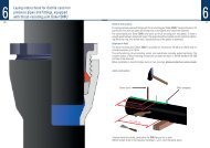
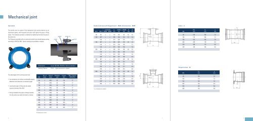
Mechanical joint<br />
description<br />
The <strong>ductile</strong> <strong>cast</strong> <strong>iron</strong> gland of the mechanical joint exerts pressure on an<br />
elastomere gasket, which expands and seals itself against the pipe or fitting<br />
spigot. The necessary pressure is obtained by tightening the bolts that grip in<br />
the socket rim.<br />
The <strong>fittings</strong> are available with an inside and outside fusion bonded epoxy coating<br />
according to DIN EN 14901. Special coatings are available on request.<br />
The advantages of this jointing system are:<br />
• the mechanical joint allows considerable angular<br />
deflection and tolerances on insertion length<br />
• inserting the pipe or fitting into the socket<br />
requires relatively little effort<br />
• during installation the pipes or <strong>fittings</strong> inserted<br />
into the socket can easily be turned or remove<br />
2<br />
dimensions as per isO 2531, en 545 or factory standard<br />
Working Pressure PFA16 – higher pressures on request<br />
dn<br />
no. of<br />
bolts<br />
size of<br />
bolts<br />
socket<br />
Hexagon<br />
size<br />
gasket<br />
torque<br />
nm<br />
socket rim<br />
Max. angular<br />
deflection<br />
80 3 M22 30 120 5°<br />
100 3 M22 30 120 5°<br />
125 3 M22 30 120 5°<br />
150 4 M22 30 120 5°<br />
200 5 M22 30 120 4°<br />
250 6 M22 30 120 4°<br />
300 7 M22 30 120 4°<br />
350 8 M22 30 120 3°<br />
400 9 M22 30 120 3°<br />
450 8 M27 36 300 3°<br />
500 10 M27 36 300 3°<br />
600 12 M27 36 300 3°<br />
All dimensions are in mmm<br />
bolt<br />
gland<br />
double socket tees with flanged branch – MMA / All socket tees – MMB<br />
dn 1 dn 2<br />
availability lu<br />
MMA MMB mm<br />
l MMA<br />
mm<br />
lu MMB<br />
mm<br />
e1<br />
mm<br />
e2<br />
mm<br />
80 80 x x 170 165 85 7,0 7,0<br />
100 80* x x 185 195 125 7,2 7,0<br />
100 x x 210 200 125 7,2<br />
150 80* x x 190 220 150 7,8 7,0<br />
100 x x 210 230 150 7,2<br />
150 x x 270 245 150 7,8<br />
200 80 x x 190 250 180 8,4 7,0<br />
100 x x 315 255 180 7,2<br />
150 x x 270 270 180 7,8<br />
200 x x 330 275 180 8,4<br />
250 80* x x 220 275 205 9,0 7,0<br />
100 x x 220 285 210 7,2<br />
150 x x 335 300 210 7,8<br />
200 x x 335 305 210 8,4<br />
250 x x 390 320 210 9,0<br />
300 80* x x 220 305 235 9,6 7,0<br />
100 x x 220 310 235 7,2<br />
150 x x 335 325 235 7,8<br />
200 x x 335 330 235 8,4<br />
250* x x 450 345 240 9,0<br />
* acc. to manufacturer‘s standard<br />
300 x x 450 360 240 9,6<br />
7<br />
<strong>Co</strong>llars – U<br />
dn<br />
Ø d<br />
mm<br />
lu<br />
mm<br />
e<br />
mm<br />
80 109 160 7,0<br />
100 130 160 7,2<br />
150 183 165 7,8<br />
200 235 170 8,4<br />
250 288 175 9,0<br />
300 340 180 9,6<br />
Flanged sockets – eU<br />
dn<br />
lu<br />
mm<br />
e<br />
mm<br />
80 105 7,0<br />
100 110 7,2<br />
150 120 7,8<br />
200 120 8,4<br />
250 125 9,0<br />
300 130 9,6<br />
8