düker ductile cast iron fittings - Düker GmbH & Co KGaA
düker ductile cast iron fittings - Düker GmbH & Co KGaA
düker ductile cast iron fittings - Düker GmbH & Co KGaA

Create successful ePaper yourself
Turn your PDF publications into a flip-book with our unique Google optimized e-Paper software.
9<br />
double socket tapers – MMR<br />
dn 1 dn 2<br />
lu<br />
mm<br />
e1<br />
mm<br />
e2<br />
mm<br />
100 80* 90 7,2 7,0<br />
150 80* 190 7,8 7,0<br />
100 150 7,2<br />
200 80 290 8,4 7,0<br />
100 250 7,2<br />
150 150 7,8<br />
250 80* 390 9,0 7,0<br />
100 350 7,2<br />
150 250 7,8<br />
200 150 8,4<br />
300 80* 490 9,6 7,0<br />
* acc. to manufacturer‘s standard<br />
100 450 7,2<br />
150 350 7,8<br />
200 250 8,4<br />
250* 150 9,0<br />
Fittings And vAlves<br />
dRAinAge teCHnOlOgY<br />
engineeRing<br />
glAss lining teCHnOlOgies<br />
JOBBing FOUndRY<br />
732735 / 01.09 specifications subject to change without notice.<br />
<strong>düker</strong> gmbH & <strong>Co</strong>. KgaA<br />
Hauptstraße 39 - 41<br />
d-63846 laufach<br />
germany<br />
Phone +49 6093 87-250<br />
Fax +49 6093 87-246<br />
internet: www.dueker.de<br />
e-Mail: info@dueker.de<br />
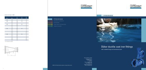
Fittings And vAlves<br />
<strong>düker</strong> <strong>ductile</strong> <strong>cast</strong> <strong>iron</strong> <strong>fittings</strong><br />
with rotatable flange and mechanical joint
Mechanical joint<br />
description<br />
The <strong>ductile</strong> <strong>cast</strong> <strong>iron</strong> gland of the mechanical joint exerts pressure on an<br />
elastomere gasket, which expands and seals itself against the pipe or fitting<br />
spigot. The necessary pressure is obtained by tightening the bolts that grip in<br />
the socket rim.<br />
The <strong>fittings</strong> are available with an inside and outside fusion bonded epoxy coating<br />
according to DIN EN 14901. Special coatings are available on request.<br />
The advantages of this jointing system are:<br />
• the mechanical joint allows considerable angular<br />
deflection and tolerances on insertion length<br />
• inserting the pipe or fitting into the socket<br />
requires relatively little effort<br />
• during installation the pipes or <strong>fittings</strong> inserted<br />
into the socket can easily be turned or remove<br />
2<br />
dimensions as per isO 2531, en 545 or factory standard<br />
Working Pressure PFA16 – higher pressures on request<br />
dn<br />
no. of<br />
bolts<br />
size of<br />
bolts<br />
socket<br />
Hexagon<br />
size<br />
gasket<br />
torque<br />
nm<br />
socket rim<br />
Max. angular<br />
deflection<br />
80 3 M22 30 120 5°<br />
100 3 M22 30 120 5°<br />
125 3 M22 30 120 5°<br />
150 4 M22 30 120 5°<br />
200 5 M22 30 120 4°<br />
250 6 M22 30 120 4°<br />
300 7 M22 30 120 4°<br />
350 8 M22 30 120 3°<br />
400 9 M22 30 120 3°<br />
450 8 M27 36 300 3°<br />
500 10 M27 36 300 3°<br />
600 12 M27 36 300 3°<br />
All dimensions are in mmm<br />
bolt<br />
gland<br />
double socket tees with flanged branch – MMA / All socket tees – MMB<br />
dn 1 dn 2<br />
availability lu<br />
MMA MMB mm<br />
l MMA<br />
mm<br />
lu MMB<br />
mm<br />
e1<br />
mm<br />
e2<br />
mm<br />
80 80 x x 170 165 85 7,0 7,0<br />
100 80* x x 185 195 125 7,2 7,0<br />
100 x x 210 200 125 7,2<br />
150 80* x x 190 220 150 7,8 7,0<br />
100 x x 210 230 150 7,2<br />
150 x x 270 245 150 7,8<br />
200 80 x x 190 250 180 8,4 7,0<br />
100 x x 315 255 180 7,2<br />
150 x x 270 270 180 7,8<br />
200 x x 330 275 180 8,4<br />
250 80* x x 220 275 205 9,0 7,0<br />
100 x x 220 285 210 7,2<br />
150 x x 335 300 210 7,8<br />
200 x x 335 305 210 8,4<br />
250 x x 390 320 210 9,0<br />
300 80* x x 220 305 235 9,6 7,0<br />
100 x x 220 310 235 7,2<br />
150 x x 335 325 235 7,8<br />
200 x x 335 330 235 8,4<br />
250* x x 450 345 240 9,0<br />
* acc. to manufacturer‘s standard<br />
300 x x 450 360 240 9,6<br />
7<br />
<strong>Co</strong>llars – U<br />
dn<br />
Ø d<br />
mm<br />
lu<br />
mm<br />
e<br />
mm<br />
80 109 160 7,0<br />
100 130 160 7,2<br />
150 183 165 7,8<br />
200 235 170 8,4<br />
250 288 175 9,0<br />
300 340 180 9,6<br />
Flanged sockets – eU<br />
dn<br />
lu<br />
mm<br />
e<br />
mm<br />
80 105 7,0<br />
100 110 7,2<br />
150 120 7,8<br />
200 120 8,4<br />
250 125 9,0<br />
300 130 9,6<br />
8
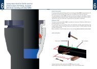
Installation instructions<br />
1. Clean socket chamber, particularly the gasket<br />
seat, the pipe or fitting spigot and the elastomere<br />
gasket. Check that the pipe or fitting spigot is in<br />
good condition.<br />
2. Slide first the gland, then the gasket, over the pipe<br />
or fitting spigot. Make sure that both are placed<br />
in the right direction as shown on the illustration<br />
on the right.<br />
3. Insert the pipe or fitting spigot into the socket<br />
down to the socket base and check the alignment.<br />
Then withdraw about 1 cm.<br />
4. Carefully slide the elastomere gasket into its seat,<br />
then slide the gland into place so it touches the<br />
gasket. Insert the bolts and nuts and tighten them<br />
by hand until they are in touch with the gland.<br />
After checking the gland position, alternately<br />
tighten the nuts with a torque spanner, adhering<br />
to the torques stated in the table on the left.<br />
5. After the pressure test, check and if necessary tighten<br />
the nuts.<br />
3
Rotatable flange<br />
Description<br />
In comparison with usual <strong>cast</strong>-on flanges, rotatable<br />
flanges facilitate the orientation of <strong>fittings</strong> and the<br />
fitting of the bolts.<br />
Installation Instructions<br />
1. Clean the faces of the flange rests, the flanges<br />
and the gasket.<br />
2. Align the pipes or <strong>fittings</strong>, leaving a small gap<br />
between the two flange rests. Insert the gasket<br />
between the flange rests and centre it. If necessary<br />
use a Neoprene adhesive to slightly fix it.<br />
DN<br />
PN<br />
bar<br />
No. of<br />
bolts<br />
Size of bolts<br />
mm<br />
Torque<br />
Nm<br />
80 10/16 8 M16 x 80 35<br />
100 10/16 8 M16 x 80 40<br />
125 10/16 8 M16 x 90 50<br />
150 10/16 8 M20 x 100 75<br />
200<br />
250<br />
300<br />
350<br />
400<br />
450<br />
500<br />
600<br />
10 8 M20 x 100<br />
16 12 M20 x 100<br />
10 12 M20 x 110<br />
16 12 M24 x 110<br />
10 12 M20 x 120<br />
16 12 M24 x 120<br />
10 16 M20 x 130<br />
16 16 M24 x 130<br />
10 16 M24 x 140<br />
16 16 M27 x 140<br />
10 20 M24 x 140<br />
16 20 M27 x 140<br />
10 20 M24 x 150<br />
16 20 M30 x 150<br />
10 20 M27 x 160<br />
16 20 M33 x 160<br />
3. Place the two halves of one rotatable flange<br />
behind one of the flange rests, watching out that<br />
the recessed inside strip is placed against the rest.<br />
Insert the two bolts on the hinges to slightly fix<br />
it, then put the second flange into place opposite<br />
the first.<br />
4. Slide through all bolts, insert the nuts and tighten<br />
them alternately crosswise.<br />
70<br />
105<br />
125<br />
130<br />
160<br />
160<br />
230<br />
345<br />
Mechanical joint sockets and glands<br />
Rotatable flanges<br />
4 5<br />
DN<br />
DN<br />
PN<br />
bar<br />
D<br />
mm<br />
a<br />
mm<br />
c<br />
mm<br />
Weight<br />
flange kg<br />
K<br />
mm<br />
80 10/16 200 23 3 2,0 160<br />
100 10/16 220 23 3 2,2 180<br />
150 10/16 285 26 3 4,2 240<br />
200<br />
250<br />
300<br />
Ø d1<br />
mm<br />
Ø d2<br />
mm<br />
Ø d3<br />
mm<br />
t<br />
mm<br />
Weight<br />
gland kg<br />
80 98 22 101 90 2,7<br />
100 118 22 121 92 3,4<br />
150 170 22 173 98 5,0<br />
200 222 22 225 104 6,0<br />
250 274 22 277 104 6,9<br />
300 326 22 329 105 8,7<br />
10 340 29 3 6,2 295<br />
16 340 29 3 5,2 295<br />
10 395 32 3 8,4 350<br />
16 400 32 3 7,6 355<br />
10 455 36 4 10,8 400<br />
16 455 36 4 11,0 410
Range of products<br />
With mechanical joint and / or rotatable flange<br />
6<br />
Double socket bends 90° – MMQ<br />
DN<br />
Lu<br />
mm<br />
e<br />
mm<br />
80 100 7,0<br />
100 120 7,2<br />
150 170 7,8<br />
200 220 8,4<br />
250 270 9,0<br />
300 320 9,6<br />
* acc. to manufacturer‘s standard<br />
Double Socket Bends 45° – MMK 45<br />
Double Socket Bends 22 ½° – MMK 22<br />
Double Socket Bends 11 ¼° – MMK 11<br />
DN<br />
Lu MMK 45<br />
mm<br />
Lu MMK 22<br />
mm<br />
Lu MMK 11<br />
mm<br />
e<br />
mm<br />
80 55 40 30 7,0<br />
100 65 45 35 7,2<br />
150 85 55 40 7,8<br />
200 110 65 45 8,4<br />
250 130 75 50 9,0<br />
300 155 90 60 9,6<br />
* acc. to manufacturer‘s standard