Read article - Höganäs AB
Read article - Höganäs AB
Read article - Höganäs AB
- TAGS
- article
- www.hoganas.com

You also want an ePaper? Increase the reach of your titles
YUMPU automatically turns print PDFs into web optimized ePapers that Google loves.
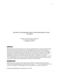
Surface densified P/M gears made of chromium alloy powder reach automotive quality<br />
Senad Dizdar, Linnéa Fordén and David Andersson<br />
<strong>Höganäs</strong> <strong>AB</strong>, R&D, 263 83 <strong>Höganäs</strong>, Sweden<br />
<strong>AB</strong>STRACT<br />
A final-drive idle helical gear from a passenger car transmission was made of water atomized<br />
and fully pre-alloyed Fe-1.5Cr-0.2Mo powder. The gear samples were cold compacted to 7.1<br />
g/cm 3 , sintered, surface densified by radial gear rolling and casehardened. A 3D gear measurement<br />
center was used to evaluate profile, alignment, pitch and runout deviations of the<br />
gears after the gear rolling and after the casehardening. The gears achieved an overall DIN 7<br />
quality after rolling for all single deviations suggested in DIN 3961 to have general or particular<br />
importance for uniformity of rotation, load capacity and noise reduction of gear. After the<br />
low-pressure casehardening, the overall gear quality for the deviations as above was DIN 7,<br />
except for the total profile deviation Fα, which achieved DIN 10 quality. To achieve DIN 7<br />
gear quality after casehardening, further work should include activities on reduction of the<br />
tooth width contraction along the tooth height.<br />
INTRODUCTION<br />
Gear quality DIN 7 or higher is one of main demands which automotive industry put on<br />
transmission gears. DIN 7 gear quality may be understood as a compromise between the total<br />
gear manufacturing cost and the gear performances including service life, load capability and<br />
noise-vibration-harshness properties. The two former gear performances have been improved<br />
by better steels and improvements in heat treatment and after treatment, while the latter has<br />
been approached using different strategies. The most straightforward is to improve the geometry<br />
of the gear itself, meaning better DIN classes.<br />
P/M gears with sintered density of 7.1 g/cm 3 manufactured by using pressing-sinteringhardening<br />
routes usually achieve gear quality no higher than DIN 10 [1]. Improvements can<br />
be gained by increasing the sintered density by means of warm compaction combined with<br />
second pressing [1] or high velocity compaction combined with sinter-hardening [2]. However,<br />
one, or a few finishing operations appears to be necessary to achieve DIN 7 gear quality.<br />
Soft finishing operations such as rolling or shaving, which are conducted before heat treatment,<br />
can be the last machining if followed by a hardening process, which keep the gear quality<br />
inside of the gear quality specification. The hardened gears are however often hard finished<br />
by grinding or honing to achieve DIN 7 gear quality.<br />
Among a variety of soft-finishing technologies, gear rolling is considered as a forming operation<br />
with high productivity, capable to fine tune the gear flank form after hobbing/cutting and<br />
reduce the flanks’ surface roughness [3]. Considering P/M gears, the gear rolling gains a new<br />
Presented at EURO PM2005 in Prague, on October 5, 2005 1
dimension – possibility to create a full-dense gear flank from the surface up to a certain depth<br />
while the core remains at the base density level [4]. Such densified layer will then be able to<br />
carry the high contact pressures at the gear flanks or the high bending stress gradients in the<br />
root fillet [4]. A number of reports provide more comprehensive information about gear surface<br />
[5-9] Paper [10] shows recent achievements in quality and tooth root load capacity of a<br />
spur and a helical P/M prototype gear for P/M automotive transmissions.<br />
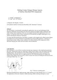
The gear quality deviations need to be briefly described before they are discussed. They are<br />
grouped into gear flank line, profile, pitch and runout deviations. In fact, the measured flank<br />
line is enveloped by two equidistant nominal lines and inspected for the line’s form deviation<br />
ffβ, angular deviation (slope) fHβ and total deviation Fβ (Figure 1 left). Often, the flank line deviation<br />
is called as “helix deviation”. Gear flank profile deviations describe how the flank profile<br />
deviate from the nominal involute flank profile including profile top correction (crowning).<br />
The deviations are analogously defined to the flank line deviations with the difference<br />
that the measured profile line is enveloped by two equidistant nominal involutes and inspected<br />
for the profile’s form deviation ffα, angular deviation (slope) fHα and total deviation Fα.<br />
Pitch deviations describe variation of the pitch - distance between adjacent tooth flanks<br />
(Figure 1 right). The pitch deviations are: the single normal pitch deviation fu, the difference<br />
between adjacent pitches fp, the total cumulative pitch deviation Fp, and cumulative circular<br />
pitch error over z/8 pitches Fpz/8. Run-out deviation Fr describes eccentricity between the gear<br />
pitch diameter and the bore of the gear rim.<br />
Figure 1 Gear flank line (left) and pitch deviations (right) [11].<br />
The P/M gear-manufacturing route for the commercial variant of the test gears in this investigation<br />
will comprise pressing, sintering, rolling, casehardening and bore grinding. Gear pressing<br />
is done in dies with a very high geometrical quality. The bore eccentricity caused by the<br />
tooling core clearance, sintering and heat treatment distortions is present but is later eliminated<br />
by the bore grinding. The gear rolling itself is an involute generating operation so that<br />
the pitch deviations of the rolled P/M gears are very small due to a high accuracy of the rolling<br />
dies. In the same way, there are good prerequisites for small profile and flank deviations.<br />
However, this must be considered together with local inconsistency of the surface material<br />
displacement along and across the tooth flank due to local variations in the porosity distributions.<br />
On the other side, local flank line and profile deviations, if they exist, may have a minor<br />
effect on the profile and flank line slopes, fHα respective fHβ.<br />
A very particular chapter of gear engineering is running-in. The running-in cannot be prevented<br />
from happening, and it normally improves the gear quality.<br />
Another aspect of the gear quality is the surface roughness of the gear flanks. In particular,<br />
this is important for the formation of the separating hydrodynamic oil film between the gear<br />
flanks in contact. Furthermore, a smooth surface of the gear tooth root is beneficial to fatigue<br />
strength of the tooth root.<br />
Presented at EURO PM2005 in Prague, on October 5, 2005 2
This paper focuses on P/M gears with sintered density of 7.1 g/cm 3 which were surface densified<br />
by radial gear rolling to achieve the performance level required by the automotive industry<br />
but at a lower total cost for the gear manufacturing. The aspects of gear quality will be discussed<br />
in some detail.<br />
EXPERIMENT<br />
A final-drive idle helical gear from a passenger car transmission was manufactured by pressing-sintering-machining-rolling-case<br />
hardening route. The gear and its manufacturing were<br />
described in more details in [10], but the gears need to be briefly described here for the scope<br />
of this investigation. The gears were pressed from a mix of Astaloy CrL (Fe-1.5Cr-0.2Mo)<br />
with addition of 0.2 wt% carbon and 0.8 wt % amide wax. Astaloy CrL is a water atomized<br />
iron powder in which chromium and molybdenum are fully pre-alloyed. The powder is completely<br />
nickel–free and provides high compressibility with near-zero dimensional change after<br />
sintering. The sintered components made of this powder gain high yield strength and high<br />
hardness and are suitable for applications with medium-range demands.<br />
To avoid high tooling cost for this gear prototype manufacturing, simple Ø80x25 mm cylindrical<br />
pucks were pressed using a 4 MN hydraulic press. The pucks were sintered in a belt<br />
furnace at 1120°C for 30 min. in 90% N2/10% H2 atmosphere with carbon potential of 0.2%.<br />
Gear blanks ready-for-rolling were then machined by turning of the faces, the OD and ID followed<br />
by gear hobbing. The blanks were rolled using a CNC cold rolling machine with two<br />
rolling dies (Escofier H20 CN) suitable for forming threads, knurls, splines or other profiles,<br />
and burnishing screw threads and gear wheels. Finally, the rolled gears were low-pressure<br />
carburized using acetylene at 960 °C for 8 min. exclusive diffusion periods of time, and subsequently<br />
quenched using nitrogen gas with a pressure of 10 bars. The heat-treated parts have<br />
a martensitic microstructure in the surface and the structure in the core is bainitic with a small<br />
amount of low carbon martensite. The case depth achieved after case hardening is 0.55<br />
mm/550 HV0.1 on the flanks.<br />
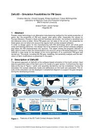
Figure 2. Test gear<br />
Number of teeth z2 28<br />
Module mn 2 mm<br />
Pressure angle αn 15°<br />
Helix angle β 32°<br />
Face width b 18.7 mm<br />
Addendum modif. coeff. x 0.137<br />
Counter gear number of teeth z1 40<br />
Axis distance a 80 mm<br />
Table 1. Test gear geometry<br />
Figure 2 shows a photograph of the test gear and Table 1 lists the test gear geometry.<br />
The quality of the gears in this study was evaluated by measurement of the gear geometry and<br />
the surface roughness of the gear flanks. Measurement of the gear geometry deviations was<br />
conducted on a commercial 3D CNC gear measuring center according to the according to<br />
DIN-standards [11],[12] using a 1.0 mm ruby stylus.<br />
RESULTS AND DISCUSSION<br />
Table 2 lists gear quality single deviations of the gears after rolling and after casehardening.<br />
As seen, the quality for single deviations has quite a large variation both between rolled and<br />
Presented at EURO PM2005 in Prague, on October 5, 2005 3
casehardened gear condition and between single deviations and their groups. The pitch deviations<br />
are all in DIN 6 or higher quality class. This is fully in accordance with the gear teeth<br />
generating aspect of the gear rolling. The helix deviations vary between DIN 6-9 quality both<br />
after rolling and after casehardening. The profile deviations meet DIN 6-7 after rolling but<br />
DIN 8-11 after casehardening. Obviously, the profile deviations experienced the largest quality<br />
drop.<br />
Deviation Symbol<br />
After<br />
rolling<br />
After<br />
case-ardening<br />
General<br />
importance<br />
Rotational uniformity<br />
Load<br />
capacity<br />
Profile form deviation ffα 7 8<br />
Profile angular deviation fHα 7 11<br />
Profile total deviation Fα 7 10 Yes Yes<br />
Helix form deviation ffβ 6 6<br />
Helix profile deviation fHβ 7 7 Yes Yes<br />
Helix total deviation Fβ 7 9<br />
Single normal pitch deviation fu 6 6<br />
Difference between adjacent pitches fp 6 6 Yes<br />
Total cumulative pitch deviation Fp 5 6 Yes Yes<br />
Cumulative circular pitch error over z/8 pitches Fpz/8 5 6<br />
Tooth thickness variation Rs 2 5<br />
Runout tolerance Fr * - - Yes<br />
*The gear measuring centre evaluated the run-out deviation Fr, according to teeth geometry neglecting the real bore eccentricity, which<br />
need to be adjusted by using bore grinding or similar machining.<br />
Table 2. Gear quality single deviations of the gears after rolling and after case-hardening according to DIN 3960,<br />
3961 and 3962.<br />
Trying to express a general quality class for such gears could give very doubtful assessments<br />
if one try to consider a deviation with the lowest quality class or some kind of mean quality<br />
class. DIN 3961 [11] suggests a way to assess how the single gear deviations influence the<br />
gear performances. Right part of Table 2 indicates the general and particular influence of single<br />
gear deviations on uniformity of rotation, load capacity and noise-vibration-harshness<br />
properties of a gearbox.<br />
By assessing in this way, the gear quality after rolling was DIN 7. After case-hardening, the<br />
gear quality was still DIN 7 except for four of the measured deviations. The total profile deviation<br />
Fα, reached quality DIN 10. In the profile angular deviation, fHα, also known as profile<br />
slope, one can see the quality change from DIN7 to DIN11, the largest quality change among<br />
all the deviations. The profile form deviation dropped one quality class from DIN 7 to DIN 8.<br />
However, looking at several measurements this may not be a general trend, but rather an isolated<br />
event due to debris on the surface. The last deviation to drop after heat treatment is the<br />
helix total deviation, Fβ, which drops two quality classes to DIN 9. However, the helix profile<br />
deviation, fHβ, remains in DIN 7, but the average value move from one end of the tolerance<br />
band (6,65 µm) to the other (7,5 µm). The tolerance band is ±11 µm for DIN 7.<br />
Such a large flank profile quality decrease needs to be discussed in more detail. Figure 3<br />
shows typical involute profiles of the test gears after gear rolling and after casehardening.<br />
The tooth thickness decreases, especially near the tooth tip. During the rolling, the surface<br />
layer is deformed plastically. This material will exhibit compressive residual stresses after<br />
rolling. These stresses are balanced by tensile stresses in the core. The tensile stresses in the<br />
core are balanced by the compressive stresses in the deformed surface layer. Since the cross<br />
section decreases towards the tooth tip and the deformed layer that has approximately constant<br />
thickness, the tensile stresses must increase in this direction. During heat treatment,<br />
Presented at EURO PM2005 in Prague, on October 5, 2005 4
these stresses are released resulting in a shorter (0,015 mm) and thinner tooth. This increase in<br />
flank slope is characteristic of the rolling and heat treatment processes used. This means that<br />
the deviations can be compensated for during the rolling process.<br />
The helix deviations have the same origin as the profile deviations described above, the helix<br />
tries to unwind, thus decreasing the helix angle. This phenomenon can also be compensated<br />
for during the rolling process.<br />
In additions to these systematic deviations, there are of course deviations that can be considered<br />
stochastic processes that cannot be compensated for by changes in geometry before heat<br />
treatment. These deviations must be limited by proper material and process control.<br />
Figure 3. Typical involute profiles of the test gears after gear rolling and after case-hardening. The profile curves<br />
belong to the same gear flank, and they were drawn over the scanned profiles from the gear measuring center<br />
chart. SAP stands for start-of-active-profile and EAP stands for end-of-active-profile of the gear tooth flank.<br />
This report focused on a quality issue of the P/M transmission gears for automotive applications.<br />
The higher gear quality the higher gear performances - it is a widely accepted motto in<br />
the automotive industry. However, the investigation [13] showed the load capability of a<br />
gear/gear pair might depend more on the gear basic geometry parameters and the particularity<br />
of the gear application, than on the single gear deviations. In particular, this was observed on<br />
the final drive gears with a large helical angle like the gear in this investigation.<br />
Surface roughness of the test gears.<br />
Roughness parameter P/M (rolled) Wrought reference (ground)<br />
Arithmetic mean profile height Ra (µm) 0.16±0.02 0.25±0.12<br />
Root-mean-square profile height Rq (µm) 0.21±0.02 0.34±0.17<br />
Ten-point-height of the profile Rz (µm) 0.94±0.12 1.47±0.83<br />
Maximum profile height Rmax (µm) 1.29±0.37 2.40±1.80<br />
Measured with a sliding shoe-type roughness tester, using cut-off filter λc = 0.25 mm.<br />
Table 3. Surface roughness of the test gear flanks<br />
Another aspect of the gear quality is surface roughness of the gear flanks. Table 3 lists surface<br />
roughness of the test gears. Both mean, Ra and Rq, and extreme value parameters, Rz and Rmax,<br />
are approximately 30% lower for the rolled P/M gear in comparison with ground wrought reference<br />
gear. This confirmed the finding of the previous works [3],[10].<br />
Presented at EURO PM2005 in Prague, on October 5, 2005 5
CONCLUSIONS<br />
Surface densified P/M transmission gears were produced by pressing, sintering, machining,<br />
rolling and casehardening. The gears were measured according to DIN standard and following<br />
conclusions were reached:<br />
• The gears achieved an overall DIN 7 quality after rolling for all deviations suggested<br />
in DIN 3961 to have general or particular importance for uniformity of rotation, load<br />
capacity and noise reduction of gears.<br />
• After the low-pressure casehardening, the overall gear quality for the deviations as<br />
above was DIN 7, except for the total profile deviation Fα, which was DIN 10 quality.<br />
• To achieve DIN 7 gear quality after casehardening, further work should include activities<br />
on compensation for or reduction of the tooth width contraction along the tooth<br />
height.<br />
REFERENCES<br />
[1] T. A. Bequette, S. M. Clase, Achieving AGMA 10 quality level for automotive gear application,<br />
SAE PM Apllications SP-1447, (1999), pp. 9-14.<br />
[2] S. Dizdar, P. Skoglund, S. Bengtsson, Process, quality and properties of high-density P/M<br />
gears, Adv. Powd. Metall. Particul. Matter., 9 (2003) pp. 36-46<br />
[3] J. Dugas, Gear Finishing by Shaving, Rolling & Honing ‚ Part 1, Gear Technology,<br />
March/April 1992, pp.14-21.<br />
[4] Y. Takeya, T. Hayasaka, M. Suzuki, Surface Rolling of Sintered Gears, SAE Int. Cong.<br />
and Exp., Detroit, Michigan, February 22-26, 1982, SAE Paper No 820234.<br />
[5] C.M. Sonsino, G. Schlieper, J. Tengzelius, Influence of as-sintered material strength on<br />
the improvement of fatigue behaviour by surface rolling, Powd. Metall., 90 (1990) pp. 2-6,<br />
[6]. Steindorf, Schwing- und Wälzfestigkeitseigenschaften von Sinterstählen unter optimierten<br />
Festwalzbedingungen, VDI Fortschrittsberichte Nr. 245, VDI-Verlag Düsseldorf 1991<br />
[7] T.M. Cadle, C.J. Landgraf, P. Brewin, P. Nurthen, Rolling Contact Fatigue Resistance of<br />
P/M Steel--Effects of Sintering Temperature and Material Density, Adv. Powd. Metall. Particul.<br />
Matter., 1 (1991) pp. 175-182<br />
[8] P.K. Jones, K. Buckley-Golder, R. Lawcock, R. Shivanath, “Densification strategies for<br />
high endurance P/M components”, Int. J. Powd. Metall., 33-3 (1997) pp. 37-44.<br />
[9] P.K. Jones, K. Buckley-Golder, H. David, R. Lawcock, D. Sarafinchan, R. Shivanath, L.<br />
Yao, “Fatigue Properties of Advanced High Density Powder Metal Alloy Steels for High Performance<br />
Powertrain Applications”, Proc. Powd. Metall. World Congr. and Exhib., Grenada,<br />
Spain 1998 , 3 (1998) pp. 155-166.<br />
[10] S. Bengtsson, L. Fordén, M. Bergström, C. Kulyenstierna, Surface densification of spur<br />
and helical gears, Presented at 2005 Int. Conf. Powd. Metall. Particul. Matter., June 19-23<br />
2005, Montreal, Canada<br />
[11] DIN 3960, Accuracy of cylindrical gears; general bases, Beuth Verlag, Berlin, 1978.<br />
[12] DIN 3961, Accuracy of cylindrical gears; tolerances for individual errors, Beuth Verlag,<br />
Berlin, 1978.<br />
[13] A. Piazza, M. Uberti, Influence of gear tooth flank deviations classes on vehicle gear performances,<br />
Proc. Int. Conf. on Gearing, Trans., and Mech. Systems, 3-6 July 2000, Nottingham<br />
Trent University, UK, Prof. Eng. Publ. Ltd., Burry St. Edmunds.<br />
Presented at EURO PM2005 in Prague, on October 5, 2005 6