Read article - Höganäs AB
Read article - Höganäs AB
Read article - Höganäs AB
- TAGS
- article
- www.hoganas.com

Create successful ePaper yourself
Turn your PDF publications into a flip-book with our unique Google optimized e-Paper software.
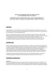
L. Fordén 1) , S. Bengtsson 1)<br />
K. Lipp 2) and C.M. Sonsino 2)<br />
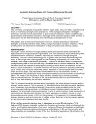
Rolling Contact Fatigue Design Aspects<br />
of Surface Densified PM Components<br />
1) <strong>Höganäs</strong> <strong>AB</strong>, <strong>Höganäs</strong> / Sweden<br />
2) Fraunhofer-Institute for Structural Durability LBF, Darmstadt / Germany<br />
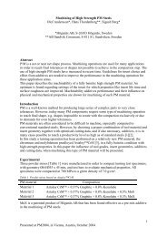
Abstract<br />
The PM industry is permanently expanding the applications into new and challenging fields.<br />
Sintered components are becoming more and more frequent for highly loaded components also<br />
under rolling contact conditions. Gears are successfully introduced for applications such as oil<br />
pumps. An important field of future expansion for PM materials are highly loaded gears in e.g.<br />
vehicle transmission and power train gears.<br />
To ensure that PM materials have the ability to compete with wrought steels, rolling contact fatigue<br />
investigations have been performed on molybdenum pre-alloyed PM materials. A summary of<br />
design aspects under rolling contact conditions for surface densified PM components will be<br />
discussed studying the surface and sub-surface stress distribution.<br />
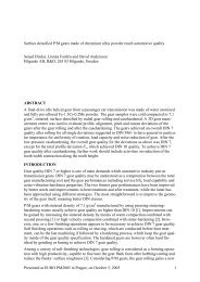
1 Introduction<br />
PM technology is a cost effective method of producing components with complicated geometries<br />
like gears. Transmission gears are subjected to rolling contact fatigue at the gear flanks and tooth<br />
bending fatigue. The development of new PM materials and processes lead to a potential for<br />
substituting conventional cast or wrought products by PM. Material properties for fatigue and<br />
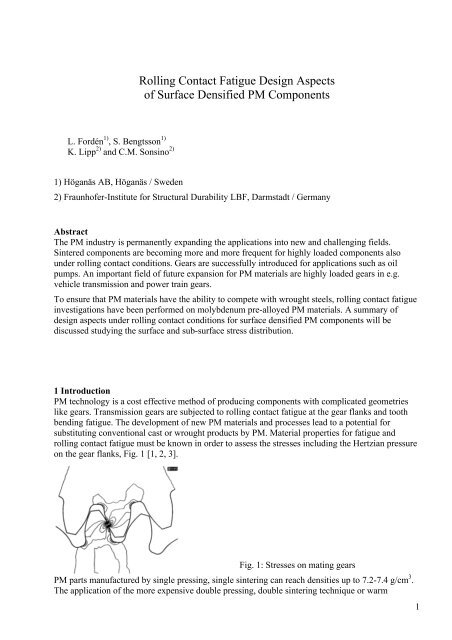
rolling contact fatigue must be known in order to assess the stresses including the Hertzian pressure<br />
on the gear flanks, Fig. 1 [1, 2, 3].<br />
Fig. 1: Stresses on mating gears<br />
PM parts manufactured by single pressing, single sintering can reach densities up to 7.2-7.4 g/cm 3 .<br />
The application of the more expensive double pressing, double sintering technique or warm<br />
1
compaction will not necessarily result in a better rolling contact fatigue behaviour [2, 4, 5].<br />
However, highest endurable Hertzian pressures will be achieved by full density, e.g. powder forging<br />
[2, 4].<br />
The surface densification technique has been developed in order to increase the load bearing<br />
capacity of PM gears [6-13]. For highly loaded gears, advantages will be given by a surface<br />
densification, where the economic single pressing, single sintering process is combined with the<br />
properties of the full density in the highly loaded areas of the gear flank and the tooth root [8, 11].<br />
The technique can hence be an alternative to conventional methods to manufacture highly loaded<br />
gears to a low cost with properties comparable to wrought steel.<br />
2 Materials and manufacturing of test specimen<br />
Rolling contact fatigue test specimens were manufactured by cold compaction, sintering at 1120°C<br />
for 30 minutes in 90H2/10N2 and soft machining to the required shape with an over measure on the<br />
diameter of test surface. The surface densification was performed by radial rolling in a two-roll<br />
burnishing machine at Escofier Technologie SA in France. The diameter was reduced by 0.5 mm<br />
during rolling; resulting in full or near full density in the surface while the core material remained<br />
unchanged. Also the shape and the surface roughness of the component were improved by the<br />
rolling. The surface densified rollers were case carburised, quenched in oil and tempered. The base<br />
powders and the reference wrought steel that were used in this study are listed in Table 1 together<br />
with their chemical composition.<br />
Table 1: Characteristics of investigated test specimens<br />
Base powder Graphite<br />
(%)<br />
Density<br />
(g/cm 3 )<br />
As-sintered<br />
hardness<br />
(HV10)<br />
Densification<br />
depth +<br />
(mm)<br />
Case depth<br />
(mm)<br />
A Astaloy 85Mo (0,85%Mo) 0.5 7.1 165 1.0 Not defined ++<br />
B Distaloy DC-1 (2%Ni diffusion<br />
bonded, 1,5%Mo pre-alloyed)<br />
0.15 7.0 142 0.9 0.75<br />
C Astaloy Mo (1,5% Mo prealloyed)<br />
0.6 7.2 189 1.0 Not defined ++<br />
+ Distance from the densified surface where the density drops to 98% of theoretical, measured by image analysis. ++ The<br />
hardness exceeded 550HV0.1 throughout the cross section [14].<br />
3 Economical aspects<br />
The benefits of combining PM technology and surface densification compared to conventional<br />
manufacturing methods are mainly economical. Fig. 2 shows a comparison of the estimated cost of<br />
some gear manufacturing routes, i.e. (1) cold compaction and sintering, (2) cold compaction,<br />
sintering and surface densification [15], (3) powder forging [15-17] and (4) machining of wrought<br />
steel. As can be seen in Fig. 2, the additional cost for the surface densification operation is<br />
comparable to pressing and sintering. The cost for the rolling operation is significantly lower<br />
compared to a powder forging procedure. It can be seen that hobbing, turning and shaving are very<br />
costly operations in contrast to pressing sintering and rolling. Into the bargain, the surface finish<br />
will be radically improved by the rolling operation compared to shaving [12].<br />
2
(1) PM<br />
(2) PM + SD<br />
(3) PF<br />
(4) Conv.<br />
0,66<br />
1,1<br />
1,1<br />
1,1<br />
0,1 0,1<br />
0,1 0,1 0,1<br />
0,1 0,1<br />
0,44<br />
0,4<br />
0,44<br />
1,74<br />
0,44<br />
1,84<br />
2,14<br />
0,7 1,4 1,4<br />
0 1 2 3 4 5<br />
Material Cold compaction Sintering<br />
Surface densification Forging Turning<br />
Hobing Shaving Case hardening<br />
Fig. 2: Cost comparison of (1) cold compaction, sintering and case hardening, (2) cold compaction,<br />
sintering, surface densification and case hardening, (3) cold compaction, sintering, powder forging<br />
and case hardening (4) turning, hobbing, shaving and case hardening.<br />
4 Rolling contact fatigue testing<br />
4.1 Testing conditions<br />
The tests were performed in a ZF-RCF test bench with the loading principle and specimen geometry<br />
shown in Fig. 3. The advantage of this testing principle is its ability to realistically simulate the load<br />
conditions on gear flanks [18]. The testing conditions were Hertzian pressure with additional sliding<br />
of -24% as the most severe condition on gear flanks, gearbox oil SAE 80 (MIL-L 2105 = GL4) and<br />
an oil temperature at the surface of the specimens of 80°C. The test is terminated either when<br />
pitting failures are detected or when the specimens has endured 10 8 cycles without failure. A<br />
vibration sensor detects pitting failures.<br />
a. Test principle<br />
Specimen<br />
b. Specimen<br />
Loading roll<br />
Contact surface Fig. 3: Test principle and specimen<br />
4.2 Endurable Hertzian Pressures of surface densified materials<br />
The results of rolling contact fatigue for the tested materials are presented in Fig. 4 using double<br />
logarithmic diagrams. The endurable Hertz pressure, estimated by linear regression and<br />
extrapolated to 10 8 cycles (endurable Hertzian pressure with a probability of survival of 50%), and<br />
the hardness characteristics are shown for all investigated materials in Table 2.<br />
Whereas the results of materials A and B will show a small scatter, the results of material C is<br />
showing a significant larger scatter in rolling contact fatigue.<br />
0,44<br />
4,6<br />
3
Hertz pressure (MPa)<br />
Hertz pressure (MPa)<br />
3000<br />
2500<br />
2000<br />
1500<br />
1000<br />
3000<br />
2500<br />
2000<br />
1500<br />
1000<br />
Material A<br />
Pitting<br />
Run-out<br />
1,E+05 10 1,E+06 1,E+07<br />
No of cycles<br />
1,E+08<br />
5<br />
10 6<br />
10 7<br />
10 8<br />
Material C<br />
Pitting<br />
Run-out<br />
1,E+05 10 1,E+06 1,E+07<br />
No of cycles<br />
1,E+08<br />
5<br />
10 6<br />
10 7<br />
10 8<br />
Table 2: Endurable Hertz pressure and hardness characteristics<br />
Surface<br />
hardness<br />
(HV0.1)<br />
Hertz pressure (MPa)<br />
3000<br />
2500<br />
2000<br />
1500<br />
1000<br />
Material B<br />
Pitting<br />
Run-out<br />
1,E+05<br />
10<br />
1,E+06 1,E+07<br />
No of cycles<br />
1,E+08<br />
5<br />
10 6<br />
10 7<br />
10 8<br />
Fig. 4: Rolling contact fatigue results<br />
Core<br />
hardness<br />
(HV0.1)<br />
Endurable Hertz<br />
pressure for 10 8 cycles<br />
(MPa)<br />
A Astaloy 85Mo+0.5% C 870 630<br />
Case depth<br />
(mm)<br />
Not defined +<br />
1350<br />
B Distaloy DC-1 + 0.15%C 945 400 0.7 1410<br />
C Astaloy Mo + 0.6%C 935 720 Not defined + 1500<br />
Reference 16MnCr5 1600 ++<br />
+<br />
The hardness exceeded 550HV0.1 throughout the cross section<br />
++<br />
source ZF Friedrichshafen and [ 4 ]<br />
All surface densified PM materials failed by pitting. The pittings look very similar to the damages<br />
in the wrought steel reference material [4]. Two types of cracks were found in the tested surface<br />
densified PM materials, i.e. small surface cracks and longer subsurface cracks running parallel to<br />
the surface, Fig 5. All the cracks were found within the densified zone. It is believed that the<br />
subsurface cracks develop to pitting damages. The small surface cracks are propagating due to the<br />
shear stresses at the surface (sliding of –24%) with a defined angle of approximately 30° into the<br />
material, Fig. 5.<br />
100 µm<br />
20µm<br />
Sub surface cracks Surface cracks Pitting damages<br />
Fig. 5: Subsurface cracks, cracks at the surface and pitting damages<br />
4
5 Subsurface stress distribution<br />
The subsurface stress distribution can be calculated for homogeneous materials using analytical<br />
formulas [20]. The contact pressure results in a three-dimensional stress field beneath the contact<br />
surface with a maximum stress in a certain depth [21, 22] taking into account only low friction<br />
forces. The subsurface stress distribution is often expressed in terms of the von Mises stress in order<br />
to give an indication about the depth of the stress maximum and the allowable load. The subsurface<br />
stress distribution is mainly effected by the geometry of the mating bodies, the density respectively<br />
the Young's modulus and the Hertzian pressure itself.<br />
In order to calculate the stress distribution of such surface densified materials with inhomogeneous<br />
Young's moduli the analytic formulas cannot be used. For this application the stress distribution was<br />
calculated using a Finite-Element-Model. Fig. 6 shows the density and the hardness distribution for<br />
the surface densified rollers of Distaloy DC-1 (B). The Young's modulus distribution was calculated<br />
on basis of the density distribution by using the formula for sintered steels [23]:<br />
Relative density (%)<br />
100<br />
98<br />
96<br />
94<br />
92<br />
90<br />
88<br />
86<br />
84<br />
82<br />
80<br />
Density<br />
Hardness HV0,1<br />
0,0 1,0 2,0 3,0<br />
Distance from surface (mm)<br />
1000<br />
900<br />
800<br />
700<br />
600<br />
500<br />
400<br />
300<br />
200<br />
100<br />
0<br />
Fig. 6: Density and hardness distribution for<br />
the investigated alloys<br />
E= E ⋅ ( ρ / ρ<br />
Microhardness HV0,1<br />
0<br />
t<br />
3.<br />
4<br />
)<br />
Fig. 7: Comparison of the sub surface stress<br />
distribution of fully dens, surface densified<br />
and porous (relative density of 87%) material.<br />
The stress distribution is shown in Fig. 7 for homogeneous full density (100%), a relative density of<br />
87%, which is the relative density in the core of the investigated samples, and for the surface<br />
densified PM material. For all calculations the same load was applied. The stresses distribution of<br />
the full density material result in the highest subsurface stresses whereas for the relative density of<br />
87% the stresses are lower. For the densified PM material the maximum subsurface stress is about<br />
4% lower than for the full density material applying the same load. In a depth of about 0.5 mm the<br />
stress distribution of the densified material converge at the stress distribution of the as sintered one.<br />
6 Discussion on design aspects for rolling contact fatigue conditions<br />
Comparing Materials A and B indicates that it is more important to have a high surface hardness<br />
than core hardness. However, material C that endured the highest Hertzian pressure of the<br />
investigated materials is characterised by high core and surface hardness. Unfortunately, the results<br />
are showing a high scatter. The results indicate that high core and surface hardness is beneficial for<br />
the rolling contact fatigue properties.<br />
Fig. 8 compares the endurable Hertz pressure of PM materials manufactured by cold compaction,<br />
warm compaction, surface densification and powder forging. The wrought steel reference material<br />
is also included. The rolling contact fatigue performance of surface densified and case hardened<br />
materials are radically improved compared to the performance of the non-densified PM materials<br />
with similar compositions. It can also be seen that surface densified PM components performs<br />
5
similarly under Hertzian pressure as powder forged components. That leads us to believe that a<br />
moderate density level (7.0-7.2g/cm 3 ) is sufficient for components that are to be surface densified.<br />
Fig. 8: Comparison of endurable Hertzian pressure<br />
The surface densified materials result in the same endurable Hertzian pressure than for the powder<br />
forged PM steels and both are very close to the case hardened wrought steel. Based on the<br />
endurable load, the surface densified PM-steels are superior compared with the powder forged PMsteels<br />
due to the stress distribution. The same endurable Hertzian pressure results in higher<br />
transferable loads, which is relevant for service applications.<br />
7 Conclusions<br />
The presented results show that the rolling contact fatigue behaviour of selectively densified and<br />
case hardened PM materials is very close to wrought steels. The more expensive powder forging<br />
procedure will not result in higher endurable Hertzian pressures.<br />
For real applications the gap between PM-materials and wrought steel regarding rolling contact<br />
fatigue behaviour will be smaller based on the transferable loads and therefore surface densified<br />
gears should be considered as a possible and economic alternative to wrought steels.<br />
Following conclusions can be summarized:<br />
• The rolling contact fatigue behaviour of PM components is radically improved by surface<br />
densification and approaches the level of wrought steels.<br />
• Surface densified PM components have very similar subsurface stress distribution under<br />
contact pressure steels as wrought steel. Hence, the same guidelines regarding for example<br />
case depth, surface hardness, residual stresses and other design parameters can be used for<br />
surface densified components as for wrought steel.<br />
• The failure mechanisms for surface densified components that are exposed to rolling contact<br />
fatigue are very similar to the failures in wrought steel.<br />
• The surface densification technique is an economic procedure compared to conventional<br />
machining and also to powder forging.<br />
8 References<br />
1) C.M. Sonsino, K. Lipp "Rolling Contact Fatigue Properties of Selected PM-Materials for Gear-Box<br />
Applications" Paper No. 99M-9, SAE International Congress and Exhibition, Detroit, Michigan, March<br />
1-4, 1999<br />
6
2) K. Lipp, C.M. Sonsino, D. Pohl "Rolling Contact Fatigue Behavior of Sintered Steels - Endurable<br />
Hertzian Pressures and Damage Mechanisms" Powder Metallurgy World Congress & Exhibition<br />
(1998), 3, S. 143-148, PM'98, Granada, Spain, 18-22.10.1998<br />
3) C.M. Sonsino "Concepts and Required Material Data for Fatigue Design of PM'Components" Euro-PM,<br />
Nizza, 2001<br />
4) K. Lipp "Oberflächenzerrüttung von Sinterstählen unter konstanter und veränderlicher Hertzscher<br />
Pressung mit überlagerter Reibung (Schlupf)" Dissertation, Universität des Saarlandes, Saarbrücken,<br />
1997, LBF-Report No. FB-210, Fraunhofer-Institut Betriebsfestigkeit, 1997<br />
5) K. Lipp, G. Hoffmann "Design for Rolling Contact Fatigue" 2002 World Congress on Powder<br />
Metallurgy & Particulate Materials, Orlando/USA, 2002<br />
6) Y. Takeya, T. Hayasaka, M. Suzuki, ”Surface Rolling of Sintered Gears”, SAE International Congress<br />
and Exposition, Detroit, Michigan, February 22-26, 1982, Paper No 820234.<br />
7) C.M. Sonsino, G. Schlieper, J. Tengzelius, “Influence of as-sintered material strength on the<br />
improvement of fatigue behaviour by surface rolling”, In: Powder Metallurgy 90, July 2-6, (1990)<br />
8) H. Steindorf "Schwing- und Wälzfestigkeitseigenschaften von Sinterstählen unter optimierten<br />
Festwalzbedingungen" VDI Fortschrittsberichte Nr. 245, VDI-Verlag Düsseldorf 1991<br />
9) T.M. Cadle, C.J. Landgraf, P. Brewin, P. Nurthen, “Rolling Contact Fatigue Resistance of P/M Steel--<br />
Effects of Sintering Temperature and Material Density”, Advances in Powder Metallurgy--1991. Vol. 1,<br />
Chicago, Illinois, USA, 9-12 June 1991, pp175-182<br />
10) P.K. Jones, K. Buckley-Golder, R. Lawcock, R. Shivanath, “Densification strategies for high endurance<br />
P/M components”, International Journal of Powder Metallurgy, vol 33, no 3, (1997), pp 37-44.<br />
11) P.K. Jones, K. Buckley-Golder, H. David, R. Lawcock, D. Sarafinchan, R. Shivanath, L. Yao, “Fatigue<br />
Properties of Advanced High Density Powder Metal Alloy Steels for High Performance Powertrain<br />
Applications”, Powder Metallurgy World Congress and Exhibition, Vol 3., October 18-22, 1998,<br />
Grenada, Spain, pp155-166.<br />
12) S. Bengtsson, L. Fordén, S. Dizdar, P. Johansson “Surface Densified P/M Transmission Gear” PM01-<br />
25: Paper presented at 2001 International Conference on "Power Transmission Components. Advances<br />
in High Performance Powder Metallurgy Applications" Ypsilanti, Michigan, USA, October 16-17, 2001<br />
13) N.N. Powder metal gears up for a hard-nosed approach, Metal Powder Report, NO 6, June, (2003),<br />
pp24-30<br />
14) S. Bengtsson, Y. Yu and M. Svensson, ”Surface densified powder metal iron alloy components<br />
production involves decarburizing the surface layer before densification by mechanical forming” Patent<br />
application WO 0200378, 2002<br />
15) ITW-gears home page: www.itwgears.com<br />
16) Pease, “Details of Progress in Powder Metallurgy”, Industrial Heating, May 1984, pp11-17<br />
17) M. Strömgren M and R Koos “Powder Forging at <strong>Höganäs</strong> <strong>AB</strong>, Sweden”, Metal Powder Report, Vol<br />
38, No 2, February1983<br />
18) G. Hoffmann, K. Lipp, K. Michaelis, C.M. Sonsino, J.A. Rice "Testing P/M Materials for High Loading<br />
Gear Applications, The Int. Journal of Powder Metallurgy – Vol. 35, No. 6, 1999<br />
19) S. Bengtsson, L. Forden "Rolling Contact Fatigue Tests of Selectively Densified Materials" 2001<br />
International Conference on Powder Metallurgy & Particular Materials, New Orleans, 2001<br />
20) L. Föppl "Der Spannungszustand und die Anstrengung des Werkstoffes bei der Berührung zweier<br />
Körper", Forsch. Ing. Wesen 7 (1936), pp. 210-215<br />
21) E. Broszeit, O. Zwirlein, J. Adelmann "Werkstoffanstrengung im Hertzschen Kontakt – Einfluß von<br />
Reibung und Eigenspannungen" Z. Werkstofftech. 13 (1992) pp. 423-429<br />
22) K.H. Kloos, E. Broszeit "Grundsätzliche Betrachtungen zur Oberflächen-Ermüdung", Zeitschrift für<br />
Werkstofftechnik 7 (1976) Nr. 3, pp. 85-124<br />
23) R.M. German "Powder Metallurgy Science" MPIF, Princeton 1994<br />
7