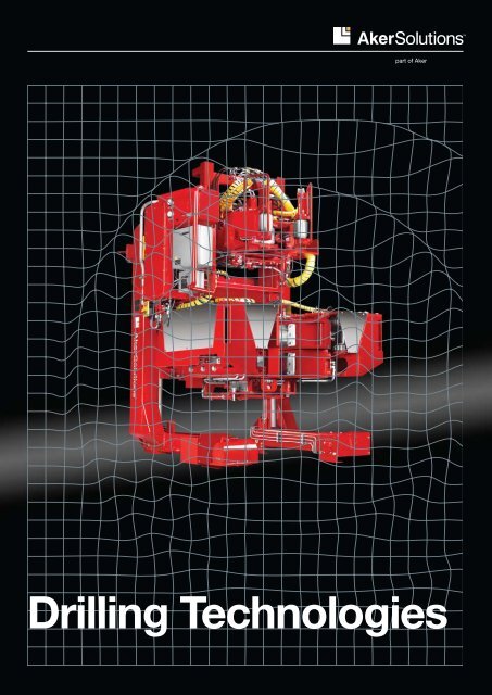
Drilling Technologies 1 - Aker Solutions
Drilling Technologies 1 - Aker Solutions
Drilling Technologies 1 - Aker Solutions

You also want an ePaper? Increase the reach of your titles
YUMPU automatically turns print PDFs into web optimized ePapers that Google loves.
<strong>Aker</strong> <strong>Solutions</strong><br />
<strong>Drilling</strong> <strong>Technologies</strong><br />
part of <strong>Aker</strong><br />
<strong>Drilling</strong> <strong>Technologies</strong><br />
1
2<br />
A world class provider of<br />
drilling technologies for the<br />
high efficiency drilling market<br />
© 2011 <strong>Aker</strong> <strong>Solutions</strong><br />
<strong>Aker</strong> <strong>Solutions</strong><br />
<strong>Drilling</strong> <strong>Technologies</strong>
<strong>Aker</strong> <strong>Solutions</strong><br />
<strong>Drilling</strong> <strong>Technologies</strong><br />
<strong>Drilling</strong> systems and technologies<br />
<strong>Aker</strong> <strong>Solutions</strong> delivers world-class deep water drilling<br />
technologies, systems and lifecycle services.<br />
We have 40 years of extensive experience from offshore drilling<br />
units. Recently, we have delivered a number of complete<br />
drilling rig packages and expanded our product portfolio<br />
significantly through acquisitions and increased focus on<br />
technologies and innovations.<br />
<strong>Aker</strong> <strong>Solutions</strong> is proud to offer support through the entire<br />
process, including engineering, manufacturing, installation<br />
and commissioning. In addition, we provide drilling lifecycle<br />
services to our customers, including spare parts, technical<br />
support, overhaul/modifications and professional rig training.<br />
Professional training and competence are key success factors<br />
in maximising uptime and ensuring safe operation of drilling<br />
equipment and drilling rigs. These are integral parts of the<br />
quality and HSE programmes in <strong>Aker</strong> <strong>Solutions</strong>. State-of-theart<br />
drilling equipment simulators are established in Norway,<br />
Singapore, Houston and Brazil.<br />
We work closely with our customers to understand their needs<br />
and provide them with drilling solutions for the future.<br />
Semi submersibles and drillships, all with <strong>Aker</strong> <strong>Solutions</strong>’ complete<br />
drilling packages installed<br />
This is <strong>Aker</strong> <strong>Solutions</strong><br />
<strong>Aker</strong> <strong>Solutions</strong> is a leading global oil services company<br />
that provides engineering and construction services,<br />
technologies, product solutions and field-life solutions for<br />
the upstream oil and gas industry. The <strong>Aker</strong> <strong>Solutions</strong> group<br />
is organised in a number of separate legal entities. <strong>Aker</strong><br />
<strong>Solutions</strong> is used as the common brand/trademark for most<br />
of these entities. <strong>Aker</strong> <strong>Solutions</strong> has aggregated annual<br />
revenues of approximately NOK 50 billion and employs<br />
approximately 20 000 people in about 26 countries.<br />
3
4<br />
<strong>Aker</strong> <strong>Solutions</strong><br />
<strong>Drilling</strong> <strong>Technologies</strong>
<strong>Aker</strong> <strong>Solutions</strong><br />
<strong>Drilling</strong> <strong>Technologies</strong><br />
Contents<br />
7<br />
<strong>Drilling</strong> rig packages<br />
Tender-assisted packages<br />
9<br />
Hoisting systems<br />
Derricks<br />
MH RamRig<br />
Wirth drawworks<br />
Drill line drum<br />
Travelling block<br />
Deadline anchor<br />
18<br />
Top drives<br />
Overview of models<br />
Game-changing modular<br />
derrick drilling machine<br />
22<br />
Drillfloor equipment<br />
Hydraulic roughneck<br />
MH TorqueMaster<br />
Drillfloor manipulator arm<br />
Multi manipulator arm<br />
Mud bucket<br />
Winches<br />
Hydraulic cathead<br />
32<br />
Hydraulic power units<br />
35<br />
Pipe handling equipment<br />
Bridge crane<br />
2-arm system<br />
Fingerboard<br />
Mousehole<br />
Pipe deck pipe handler<br />
Gantry crane<br />
Piperack crane<br />
Catwalk machine<br />
Horizontal to vertical arm<br />
Riser handling system<br />
45<br />
Compensators and<br />
tensioners<br />
Drill string compensator<br />
Active heave compensator<br />
Riser tensioners<br />
Through tubing drilling<br />
compensator<br />
Pistontrack<br />
51<br />
<strong>Drilling</strong> risers<br />
Deep water CLIP riser<br />
54<br />
BOP handling equipment<br />
BOP handling system<br />
BOP transporter<br />
Overhead crane<br />
BOP guide system<br />
Base plate trolley<br />
57<br />
<strong>Drilling</strong> fluid equipment<br />
Mud pumps<br />
Mud mixing and treatment<br />
equipment<br />
62<br />
Handling tools<br />
Drill pipe elevator<br />
Power slips frame<br />
Hydraulic rotary table<br />
Electric-driven rotary table<br />
66<br />
Personnel lifting<br />
Access basket<br />
Casing stabbing board<br />
Acknowledgements<br />
Photography:<br />
<strong>Aker</strong> <strong>Solutions</strong><br />
Erik Ruud<br />
Knut Uppstad<br />
Tine Poppe<br />
This catalogue gives an overview<br />
of <strong>Aker</strong> <strong>Solutions</strong>’ extensive drilling<br />
product range. For more details,<br />
technical specifications and tailormade<br />
solutions, please contact<br />
<strong>Aker</strong> <strong>Solutions</strong>.<br />
69<br />
<strong>Drilling</strong> control and<br />
monitoring systems<br />
Operator chair<br />
E-tally<br />
MH DrillView<br />
CCTV<br />
Robotic motion control<br />
75<br />
Control rooms and<br />
cabins<br />
<strong>Drilling</strong> control room<br />
Operator cabin<br />
78<br />
Global drilling lifecycle<br />
services<br />
Technical support<br />
Spare parts<br />
Overhaul and modification<br />
Training centres<br />
<strong>Drilling</strong> equipment simulators<br />
IPort - integrated operations<br />
Lifecycle engineering<br />
e-services<br />
Worldwide support<br />
87<br />
Contacts<br />
Copyright and legal notice<br />
Copyright in all published material<br />
including photographs, drawings<br />
and images in this brochure remains<br />
vested in <strong>Aker</strong> <strong>Solutions</strong> and third<br />
party contributors to this magazine<br />
as appropriate. Accordingly,<br />
neither the whole nor any part of<br />
this magazine can be reproduced<br />
in any form without express prior<br />
permission. Articles and opinions<br />
appearing in this brochure do not<br />
necessarily represent the views<br />
of <strong>Aker</strong> Solution. While all steps<br />
have been taken to ensure the<br />
accuracy of the published contents,<br />
<strong>Aker</strong> <strong>Solutions</strong> does not accept<br />
any responsibility for any errors<br />
or resulting loss or damage or<br />
however caused and readers have<br />
the responsibility to thoroughly<br />
check these aspects for themselves.<br />
Enquiries about reproduction of<br />
content from this magazine should<br />
be directed to <strong>Aker</strong> <strong>Solutions</strong>.<br />
5
6<br />
Our values<br />
Building<br />
customer<br />
trust is key to<br />
our business<br />
Strategic initiatives<br />
Customer relations<br />
We take personal<br />
responsibility for<br />
HSE because<br />
we care<br />
All our major<br />
achievements<br />
are team<br />
efforts<br />
Build strong and lasting<br />
relationships to individual<br />
customers<br />
Strengthen presence and<br />
select regions<br />
internationality<br />
Technology People<br />
Focus existing technology<br />
processes and initiatives in<br />
the operating businesses<br />
Identify and co-ordinate<br />
research and development<br />
initiatives<br />
We encourage<br />
early and honest<br />
communication<br />
Performance quality<br />
We know our<br />
business and get<br />
things done<br />
<strong>Aker</strong> <strong>Solutions</strong><br />
<strong>Drilling</strong> <strong>Technologies</strong><br />
Chase operational excellence<br />
(HSE, project management,<br />
cost effiency)<br />
Reduce quality costs,<br />
continue to strengthen<br />
performance culture<br />
People and leadership<br />
development<br />
We deliver<br />
consistently and<br />
strive to beat our<br />
goals<br />
Retain and attract the best<br />
and most competent people
<strong>Aker</strong> <strong>Solutions</strong><br />
<strong>Drilling</strong> <strong>Technologies</strong><br />
<strong>Drilling</strong> rig packages<br />
7
8<br />
<strong>Drilling</strong> rig packages<br />
Complete derrick equipment sets (DES) and drilling<br />
support modules (DSM) can be provided on an EPC<br />
basis. We have extensive experience from these types<br />
of projects and execute the projects according to the<br />
<strong>Aker</strong> <strong>Solutions</strong> Project Execution Model (PEM).<br />
<strong>Aker</strong> <strong>Solutions</strong> draws upon well-qualified and<br />
experienced in-house resources to participate in<br />
and/or provide the following services as part of the<br />
complete drilling facilities delivery;<br />
Project management<br />
Conceptual design/front-end engineering design<br />
Detailed engineering and procurement<br />
Supply of complete drilling equipment, mud<br />
equipment and third party equipment<br />
Fabrication, supervision and follow-up<br />
Installation supervision, commissioning and<br />
general site supervision and assistance<br />
<strong>Drilling</strong> lifecycle services<br />
Tender-assisted packages<br />
<strong>Aker</strong> <strong>Solutions</strong> is the world leader in tender-assisted<br />
rig packages operating on tender barges and tender<br />
semi submersibles all over the world. With over thirty<br />
years of experience, our tender rig packages are<br />
designed specifically for easy water transportation<br />
and quick rig-up and rig-down on multi-well platforms.<br />
These rigs break down into small packages that can<br />
be designed to meet the size and capacities of a rig’s<br />
crane. Our tender-assisted packages are particularly<br />
suited for drilling on small platforms and designed to<br />
be outfitted for top drive systems. Features for these<br />
rigs include two-way skidding, low weight package lifts,<br />
wire line raised and vertically telescoped mast, fluid<br />
tanks in substructure and optional cantilevered.<br />
<strong>Aker</strong> <strong>Solutions</strong><br />
<strong>Drilling</strong> <strong>Technologies</strong><br />
<strong>Drilling</strong> rig packages
<strong>Aker</strong> <strong>Solutions</strong><br />
<strong>Drilling</strong> <strong>Technologies</strong><br />
Hoisting systems<br />
9
10<br />
MH derricks<br />
A variety of derrick designs are offered, which typically<br />
range from 800,000 lbs to 2,500,000 lbs static hook<br />
load. <strong>Aker</strong> <strong>Solutions</strong> has an in-house engineering<br />
group, capable of supplying a multitude of derrick<br />
designs, sizes, capacities and features. We design and<br />
fabricate custom derrick geometries that meet our<br />
customer’s unique specifications requirements. These<br />
custom geometries include asymmetrical derricks,<br />
offset well center derricks, and straight taper derricks.<br />
This flexibility allows our customers to decide which<br />
design would provide the most optimal scenario.<br />
Dynamic MH derricks<br />
Whether it is for semi-submersibles, drill ships, barges<br />
or floating vessel types, we can custom design and<br />
fabricate derricks to accommodate customer specific<br />
loading and operating conditions and parameters.<br />
Variables such as roll-pitch-heave, hook load, setback<br />
load, wind speed, top drive torque, list, and center of<br />
rotation are all analysed in combination with specific<br />
operating conditions and parameters.<br />
We can design and fabricate bolted dynamic derricks,<br />
while offering a virtually unlimited variety of custom<br />
derrick sizes, capacities, design variables and<br />
conditions. These custom structures allow the<br />
customer a greater flexibility for the design criteria for<br />
the specific rig. We will build up the derricks in a 3D<br />
model for a smooth integration with the equipment.<br />
MH jack-up derricks<br />
The jack-up derricks can be designed for new<br />
builds or to replace an existing derrick during a rig<br />
upgrade. These derricks are designed with the ability<br />
to make infield moves with partial setback, while<br />
accommodating a variety of other customer-supplied<br />
equipment.<br />
Designs include vertical beam-leg bottleneck<br />
arrangement with vertical legs extending from the drill<br />
floor to above racking board elevation before sloping<br />
inward to the top of the derrick. This design expands<br />
the setback capacity, while improving driller visibility<br />
and increasing productivity. Straight tapered leg<br />
arrangement, common on many older jack-ups, where<br />
all four legs of the derrick gradually slope inward from<br />
the base to the top of the derrick is still available. This<br />
design occupies less space on the rig and reduces<br />
weight.<br />
<strong>Aker</strong> <strong>Solutions</strong><br />
<strong>Drilling</strong> <strong>Technologies</strong><br />
Hoisting systems<br />
MH offshore masts<br />
We offer a variety of structures for offshore rigs.<br />
In addition to specific derrick designs, offshore<br />
masts and substructures are also available for<br />
specific rigs. The masts are designed according to<br />
customer specifications for tender-assisted, fixed<br />
platforms, spar platforms, submersible barges and<br />
semi-submersible rigs. Designs for offshore rigs<br />
include telescoping masts, vertical assembled masts<br />
and on-floor cantilever masts. These structures<br />
are customised according to specific customer<br />
requirements.<br />
Vertical assembled masts<br />
Telescoping masts<br />
On-floor cantilever masts
<strong>Aker</strong> <strong>Solutions</strong><br />
<strong>Drilling</strong> <strong>Technologies</strong><br />
Hoisting systems<br />
MH RamRig Safety, fingerboard at drillfloor level. Less over-head<br />
operations<br />
Documented lower weight, reduced space<br />
requirements and improved safety compared to<br />
conventional drilling packages<br />
Lower centre of gravity increases variable deck load<br />
(VDL) capacity<br />
Highly flexible and accurate integrated long stroke<br />
> Dual MH RamRig TM<br />
MH RamRig represents state-of-the-art technology<br />
with a well proven and successful operational track<br />
record since 1998. It can be applied to fixed and<br />
floating drilling platforms. The concept’s inherent<br />
features make it especially competitive on deepwater<br />
rigs. The concept is available with single, double or<br />
triple stand rigs with capacities delivered from 150 to<br />
1,000 tons, and can easily meet future demands for<br />
higher hoisting capacity and setback capacity.<br />
The MH RamRig solutions have successfully<br />
operated in international waters. This opens for drilling<br />
in harsh environment and in ultra deep water areas.<br />
To operate in arctic waters it can be designed as<br />
winterised.<br />
A dual MH RamRig is the ultimate deep water rig.<br />
This rig provides dual rig functionality at a lower total<br />
operational cost than a comparable conventional dual<br />
rig solution.<br />
active/passive heave compensation and stateof-the-art<br />
control systems, improved operational<br />
efficiency<br />
The impressive accuracy and built-in automated<br />
drilling function results in a smoother well path, less<br />
weight on bit (WOB) variations and optimisation of<br />
the rate of penetration (ROP)<br />
No drawworks, considerably increased braking<br />
capacity and minimal risk of dropping the BOP/riser.<br />
Drillfloor and substructure<br />
Due to its unique design, tubulars on the MH<br />
RamRig are racked vertically from drill floor to lower<br />
setback, saving valuable deck space without reducing<br />
the rig’s drilling capacities. The concept is therefore<br />
ideal for deepwater operations. The vertical racking of<br />
tubulars has the following main advantages:<br />
All pipe handling functions are independent of the<br />
hoisting operations<br />
Opening and closing of the elevator always takes<br />
place at drill floor level, not at high level in the<br />
derrick<br />
Simplified equipment for horizontal to vertical pipe<br />
handling<br />
Reduced possibility of dropping objects<br />
The elevated drill floor also enables a very efficient<br />
and safe working environment for handling BOP and<br />
subsea equipment.<br />
11
12<br />
MH RamRig<br />
> Dual MH RamRig TM<br />
The rams, or cylinders, are of the same type as those<br />
used in the well known MH crown compensators.<br />
The cylinders are coated with a non-corrodible and<br />
durable ceramic layer extending the operating lifetime<br />
of the cylinders. The rams have a noncontact position<br />
measurement system with an accuracy of 1/100 mm.<br />
Key components<br />
The hoisting system on the MH RamRig consists<br />
of two or more cylinders (depending on capacity<br />
requirements) instead of the conventional drawworks<br />
and derrick. The hoisting lines are of fixed length,<br />
parallel lines with one end anchored at the drill floor,<br />
the other end at the top drive. The lines are run over<br />
the yoke sheaves, thereby transforming the push from<br />
the rams to upward lifting the force to the top drive.<br />
Subsequently, the travelling distance and speed of<br />
the top drive is double the stroking of the rams. The<br />
stroking velocity of the rams is maximum 1 m/s (3.3<br />
ft/s), which gives 2 m/s (6.6 ft/s) travelling speed for<br />
the top drive.<br />
Equaliser assembly<br />
The equaliser assembly at drillfloor level absorbs<br />
uneven wire stretch and ensures even load stress of<br />
the wires during their lifetime.<br />
<strong>Aker</strong> <strong>Solutions</strong><br />
<strong>Drilling</strong> <strong>Technologies</strong><br />
Hoisting systems<br />
Ram guides<br />
The ram guides replace the derrick or mast used in<br />
a conventional drilling set-up, and are built for the<br />
purpose of guiding only, not for lifting. As the load<br />
is taken by the drill floor structure, and not from the<br />
top of a derrick structure, the MH RamRig concept<br />
provides a lower weight and center of gravity. With<br />
ramguides installed, there is no need for crown block<br />
or travelling block.<br />
Hydraulic system<br />
The hydraulic system is used to power the hoisting,<br />
lowering and heave compensation operations. The<br />
system is comprised of a number of hydraulic pumps<br />
(normally 8) driven by diesel engines or constant<br />
speed AC motors, hydraulic reservoir, valves for mode<br />
selection and nitrogen accumulators. The system is<br />
highly flexible and redundant in configuration. The<br />
heave compensation system has three modes of<br />
operation. In passive mode, the nitrogen bottles are<br />
directly connected to the rams. In this mode, the<br />
system may operate continuously without the use of<br />
electric power. In semi-active mode, nitrogen bottles<br />
and the hydraulic system work together to reduce<br />
system friction. In the truly active mode, the hydraulic<br />
system is used to compensate for the heave.
<strong>Aker</strong> <strong>Solutions</strong><br />
<strong>Drilling</strong> <strong>Technologies</strong><br />
Hoisting systems<br />
Wirth drawworks<br />
> Wirth multi-speed<br />
drawworks GH 4500<br />
EG<br />
> Wirth multi-speed<br />
drawworks GH 6000<br />
EG<br />
>> Wirth multi-speed<br />
drawworks GH 2500<br />
EG<br />
<strong>Aker</strong> <strong>Solutions</strong> offers electrical Wirth drawworks<br />
concepts in classic or premium lines providing some<br />
of the most advanced drawworks in the industry.<br />
Our state-of-the-art gear-driven drawworks<br />
technology has been supplied as state-of-the-art to<br />
the oil industry for either on or offshore applications.<br />
The major reasons are improved safety, optimal<br />
performance and control, significant weight reduction<br />
and increased reliability. Combining the different<br />
performance characteristics of dynamic brake and<br />
a regenerative brake via the drive motors with an<br />
intelligent, automated drawworks control system<br />
provides a standard of performance and safety<br />
that can hardly be achieved with a chain-driven<br />
drawworks.<br />
Wirth offers three basic gear-driven drawworks<br />
concepts for different applications to suit various<br />
performance requirements.<br />
Multi-speed<br />
Two-speed<br />
Single-speed<br />
Available in a range from 1250 to 6 000 for hoisting<br />
capacities up to 314 000 lbs in conjunction with<br />
optimised hook speed.<br />
Innovation of drilling efficiency<br />
Gear-driven design<br />
With AC or DC main drive configuration<br />
Short or long version to suit every drill floor layout<br />
Supplied with all necessary control systems<br />
Providing the following advantages<br />
Three independent braking systems for the highest<br />
safety<br />
Increased life-time and endurance<br />
Higher speeds by using four quadrant drive mode<br />
Frequency-controlled AC-motors<br />
lntegrated autodriller<br />
Gear-driven design results in<br />
High performance<br />
High availability<br />
Lower weight<br />
Less noise and vibration<br />
13
14<br />
Wirth drawworks<br />
Complete state-of-the-art drawworks control<br />
packages consist of<br />
DICS - Drawworks interface and control system<br />
ZPS - Zone positioning system including dynamic<br />
anti-collision system functions<br />
ECS - Eddy current brake control system<br />
ADS - Auto-driller system<br />
WPS - Wireline protection system<br />
DBS - Dual brake system<br />
BBS - Battery back-up system<br />
ADS - auto driller system<br />
The integrated auto-driller as an independent system<br />
confirms redundancy to the main drive system.<br />
AC frequency controlled independent drive<br />
arrangement<br />
Maximised drilling effiency<br />
Automatic drilling operation<br />
Minimised downtime<br />
Smooth block control<br />
The capacity to build in an auto-driller is easily<br />
done by adding an extra AC drive arrangement,<br />
independent from the main drive system.<br />
Features<br />
Continous, automatic weight-on-bit, DDM torque,<br />
rate of penetration or pump pressure control<br />
Emergency lifting and lowering capacity<br />
Easy operation with simple handling<br />
Complete monitoring of the drilling process<br />
Enhanced safety and equipment protection<br />
Interactively settable limits for all parameters<br />
WPS - wireline protection system smoothes<br />
emergency stops<br />
This unique systems avoids bird’s nest effects, thereby<br />
optimising protection for personnel and equipment.<br />
Advantages<br />
Protects your drawworks against the bird’s nest<br />
effect<br />
Smoothes emergency stops during hoisting<br />
operations<br />
Fail-safe system<br />
Reduces downtime and equipment damage to<br />
save costs<br />
Extends the wireline lifetime<br />
Increases availability<br />
Optimises number of roundtrips<br />
Easy to retrofit on existing Wirth drawworks<br />
<strong>Aker</strong> <strong>Solutions</strong><br />
<strong>Drilling</strong> <strong>Technologies</strong><br />
Hoisting systems<br />
DBS - dual brake system redundant disc brake<br />
system<br />
Second disk brake system installed directly on the<br />
drive motor.<br />
Advantages<br />
Double disc brake system leading to double safety<br />
Fail-safe spring-operated configuration<br />
Intelligent fully redundant PLC controlled set-up<br />
Extended availability of drawworks<br />
Constant maximum brake power<br />
Provides full redundancy to main disk brake<br />
Adaption of required brake torque on conjunction<br />
with the respective hook load and speed
<strong>Aker</strong> <strong>Solutions</strong><br />
<strong>Drilling</strong> <strong>Technologies</strong><br />
Hoisting systems<br />
Wirth drawworks with 4-Q drive<br />
Single-speed<br />
Multi-speed<br />
Type GH 1250 EG DC GH 1500 EG AC GH 2000 EG DC GH 2500 EG DC GH 2500 EG AC<br />
Power rating HP 1250 1500 2000 2500 2500<br />
Hook load kN<br />
lbs x 1000<br />
2776<br />
624<br />
8-lines<br />
8-lines<br />
12-lines 14-lines 10-lines 12-lines 12-lines 14-lines<br />
Max. hook m/s 1.81 1.81 1.54 1.32 1.85 1.54 1.54 1.32<br />
Speed ft/s 5.9 5.9 5.0 4.3 6.00 5.00 5.0 4.3<br />
Product lines<br />
Wirth drawworks are available in two different product<br />
lines. The exact specifications of the products<br />
depends on customers requirements. Proven,<br />
standardised products characterise the “classic line”<br />
mainly used for onshore applications. The “premium<br />
line” products guarantee the highest quality and a<br />
tailor-made solution to suit all customer requirements.<br />
Premium line<br />
State of the art equipment<br />
Complying to the highest offshore standards<br />
Including all of the features to provide the customer<br />
with a superior product<br />
Tailor-made to best suit the customer requirements<br />
Classic line<br />
State of the art equipment<br />
Complying to onshore standards<br />
Features are optional<br />
100 percent standardised product<br />
2961<br />
665<br />
Multi-speed<br />
Type GH 3000 EG AC GH 4000 EG DC-SV GH 4500 EG AC GH 6000 EG AC GH 6000 EG-01 AC<br />
Power rating HP 3000 3750 4500 6000 6000<br />
Hook load kN 6698 7663 6951 7953 8881 10161 11900<br />
13982<br />
lbs x 1000 1505 1722 1562 1787 1996 2283<br />
2675<br />
3140<br />
12-lines 14-lines 12-lines 14-lines 12-lines 14-lines 14-lines<br />
16-lines<br />
4536<br />
1019<br />
Max. hook m/s 1.54 1.32 1.75 1.5 1.75 1.5<br />
Speed ft/s 5.0 5.7 4.9 5.7 4.9<br />
Type GH 1500 EG GH 3000 EG GH 6000 EG<br />
AC-1G<br />
AC-1G<br />
AC-1G<br />
Power rating HP 1500 3000 6000<br />
Hook load kN<br />
lbs<br />
1720 2025 2815 3449 6900 8120<br />
x 1000 386 455 632 774 1550 1825<br />
10-lines 12-lines 8-lines 10-lines 10-lines 12-lines<br />
Max. hook m/s 1.29 1.075 0.99 0.79 1.29 1.075<br />
Speed ft/s 4.23 3.52 3.22 5.57 4.23 3.52<br />
Two-speed<br />
Power<br />
rating<br />
5189<br />
1166<br />
Hook load kN<br />
lbs<br />
x 1000<br />
4458<br />
1002<br />
1.5<br />
4.9<br />
5611<br />
1180<br />
Type GH 1500 - 3000<br />
EG DC-2G<br />
5248<br />
1179<br />
1.12<br />
3.67<br />
GH 3300 EG<br />
AC-2G<br />
HP 2000 3300<br />
4914<br />
1100<br />
5622<br />
1260<br />
7920<br />
1780<br />
6004<br />
1349<br />
8890<br />
1980<br />
12-lines 14-lines 14-lines 16-lines<br />
Max. hook m/s 1.24 1.06 1.02 0.89<br />
Speed ft/s 4.06 3.05 3.34 2.91<br />
15
16<br />
MH drill line drum<br />
The MH drill line drum provides safe and reliable<br />
drill line handling in a heavy duty offshore working<br />
environment.<br />
Key features<br />
Designed for optimum performance, quality and<br />
reliability<br />
The hydraulically driven MH drill line drum<br />
provides safe and reliable drill line handling in a<br />
heavy duty offshore working environment.<br />
For quick and easy operation during cut and slip of<br />
the drill line wire is installed in a cradle equipped<br />
with hydraulic motor(s) and gearbox with brakes,<br />
intended for spooling of wire<br />
Can be delivered with drill line diameters in the<br />
range 1 3/8 - 2 in (34.9 – 50.8 mm), and also 56<br />
mm (approx. 2 3/16 in) drill line wire<br />
Can be equipped with weather cover for protection<br />
against salty and damp environments if required<br />
MH travelling block<br />
Key features<br />
Designed for optimum performance, quality and<br />
reliability<br />
Hook load capacity ranges from 350 to 1.350<br />
sh.tons<br />
Drill line wire capacity in the range 1 1/2 - 2 3/16 in<br />
(56 mm). The wire sheaves are grooved for the<br />
specified drill line wire size.<br />
The equipment is designed in accordance with<br />
API 8C<br />
<strong>Aker</strong> <strong>Solutions</strong><br />
<strong>Drilling</strong> <strong>Technologies</strong><br />
Hoisting systems<br />
Technical data<br />
Model Drill line capacity Drill line size Max line pull Max wire delivery speed<br />
BG81 10.000 - 16.500 ft (3.000 - 5.000 m) 1 3/8 - 1 3/4 in 11,2 kN (2.520 lbf) 20 m/min (66 ft/minute)<br />
BG82 10.000 ft (3.000 m) 2 in 30 kN (6.740 lbf) 18 m/min (59 ft/minute)<br />
BG83 10.000 ft (3.000 m) 56 mm 30 kN (6.740 lbf) 18 m/min (59 ft/minute)<br />
Technical data<br />
Model Hook load Drill line size Lifting lug capacity No of sheaves<br />
BX34 500 shT (454 shT) 1 1/2 - 1 5/8 in 55 shT (50 mT) 6<br />
BX31 650 shT (590 shT) 1 1/2 - 1 3/4 in 55 shT (50 mT) 7<br />
BX35 750 shT (680 mT) 1 1/2 - 1 3/4 in 55 shT (50 mT) 7<br />
BX39 1.000 shT (907 mT) 2 in 88 shT (80 mT) 7<br />
BX42 1.350 shT (1.220 mT) 56 mm 132 shT (120 mT) 8
<strong>Aker</strong> <strong>Solutions</strong><br />
<strong>Drilling</strong> <strong>Technologies</strong><br />
Hoisting systems<br />
MH deadline anchor<br />
The MH deadline anchor is used as anchor for the drill<br />
lines coming from the crown block, and is bolted to<br />
the drill floor or to the derrick leg.<br />
Key features<br />
Designed for optimum performance, quality and<br />
reliability.<br />
Used as an anchor for the drill line and is bolted<br />
either to the drill floor or to the derrick leg.<br />
Supports drill line diameters in the range 1 3/8 -<br />
2 in (34.9 – 50.8 mm), and also 56 mm (approx. 2<br />
3/16 in) drill line wire.<br />
The bit weight is measured using either hydraulic<br />
tension, hydraulic compression or electric tension<br />
load cells<br />
MH deadline anchor can be manually rotated for<br />
easy cut and slip of drill line<br />
Technical data<br />
Model Max line pull Drill line size Mounting Manual<br />
rotation<br />
Load cell type<br />
BX81 150.000 lb (68 m. tons) 1 3/8 - 1 3/4 in Floor-mounted No Hydraulic/electric tension<br />
BX82 160.000 lb (73 m. tons) 1 3/4 - 1 5/8 in Leg-mounted Yes Hydraulic compression<br />
BX83 140.000 lb (64 m. tons) 1 1/2 - 1 3/4 in Floor-mounted Yes Electric tension<br />
BX84 140.000 lb (64 m. tons) 1 1/2 - 1 3/4 in Floor-mounted Yes Hydraulic compression<br />
BX85 200.000 lb (91 m. tons) 2 in Floor-mounted Yes Hydraulic compression<br />
BX86 200.000 lb (91 m. tons) 56 mm Floor-mounted Yes Hydraulic compression<br />
17
18<br />
Top drives<br />
<strong>Aker</strong> <strong>Solutions</strong><br />
<strong>Drilling</strong> <strong>Technologies</strong>
<strong>Aker</strong> <strong>Solutions</strong><br />
<strong>Drilling</strong> <strong>Technologies</strong><br />
Top drives<br />
Top drives<br />
> MH DDM 1000AC<br />
<strong>Aker</strong> <strong>Solutions</strong> delivers reliable and flexible top drive<br />
solutions. Since 1982, our top drives have been in<br />
daily operations around the world. Our systems are<br />
designed for rough conditions and comply with the<br />
strictest approvals for the drilling industry. We provide<br />
solutions ranging from portable land rig applications to<br />
extreme deep water applications.<br />
Motors<br />
AC, DC and hydraulic motors are offered. All our drive<br />
motors are designed specifically for optimum variable<br />
speed performance and certified for operation in<br />
hazardous area.<br />
Gear boxes<br />
The top drives are equipped with high quality gear<br />
boxes. We use the highest quality selection of gears<br />
and bearings to maximise machine uptime.<br />
Pipe handlers<br />
The top drives include a remote controlled,<br />
multifunctional pipe handler. Pipe handlers can rotate<br />
freely, and are equipped with automatic positioning<br />
to ensure safe, easy and accurate orientation. Our<br />
knuckle link pipe handler is a well proven design with<br />
unique handling capabilities.<br />
Efficient directional drilling<br />
Standard AC top drives include tool face orientation<br />
system for controlling the direction of the down-hole<br />
motor. Accuracy of the deviation is easily maintained,<br />
as the direction only has to be adjusted every 90 ft<br />
(27 m).<br />
Control system and operator interfaces<br />
The top drives are delivered with MH control system<br />
for optimal operation and lifecycle support. We deliver<br />
a range of different equipment/solutions for operator<br />
environments, from the simplest stainless steel<br />
panels to the state-of-the-art MH DrillView operator<br />
environment. We also deliver interfaces to third party<br />
operator systems.<br />
VFD/AC drives<br />
Our standard delivery is ABB drives. We can also<br />
deliver interfaces to other drive types on request.<br />
19
20<br />
Overview of models<br />
MH portable top drive (PTD)<br />
Compact and light design provides:<br />
Portability and flexibility<br />
Cost effectiveness on smaller rigs<br />
Suitability for land rigs<br />
Few requirements for interface to derrick<br />
Derrick drilling machine (DDM)<br />
The broadest range provides:<br />
Wide operational performance<br />
High performance<br />
Motor range: AC, DC or hydraulic<br />
Conventional and MH RamRig drilling<br />
Modular derrick drilling machine (MDDM)<br />
High performance modular design provides:<br />
Maximum uptime<br />
Extreme performance and low failure rate<br />
Easy maintenance and overhaul<br />
Limited noise<br />
Technical data PTD DDM MDDM<br />
Lifting capacity<br />
(in linkhanger)<br />
500<br />
454<br />
<strong>Drilling</strong> torque range 30.100 - 43.900<br />
40.810 - 59.520<br />
Torque at max speed 18.800 – 29.600<br />
25.490 – 40.130<br />
650 - 1.000<br />
590 - 907<br />
59.700 - 87.000<br />
80.940 - 117.960<br />
30.000 - 39.675<br />
40.670 - 53.790<br />
*Higher speed upon request<br />
1.000 - 1.250<br />
907 - 1.130<br />
62.900 - 101.200<br />
85.280 - 137.210<br />
21.200 - 34.100<br />
28.740 - 46.230<br />
Max speed 216 - 208 220 – 240* 227 - 282 rpm<br />
Power output 800 - 1 150 1.100 - 2.300 1.270 - 2.540 Hp<br />
Weight 11.300 – 12.100 16.000 – 29.000 44.000 – 65.000 Kg<br />
Length 18.6 - 19.3<br />
5.7 - 5.9<br />
19.4 - 24.6<br />
5.9 - 7.5<br />
29.2 - 30.1<br />
8.9 – 9.4<br />
<strong>Aker</strong> <strong>Solutions</strong><br />
<strong>Drilling</strong> <strong>Technologies</strong><br />
Top drives<br />
shT<br />
mT<br />
lbf·ft<br />
Nm<br />
lbf·ft<br />
Nm<br />
ft<br />
m
<strong>Aker</strong> <strong>Solutions</strong><br />
<strong>Drilling</strong> <strong>Technologies</strong><br />
Top drives<br />
Overview of models<br />
21
22<br />
Game-changing modular<br />
derrick drilling machine<br />
> MH MDDM 1000AC<br />
<strong>Aker</strong> <strong>Solutions</strong> delivers the MH modular derrick<br />
drilling machine (MDDM) to advanced drill ships.<br />
This innovative technology gives maximum uptime,<br />
extreme performance and enhanced safety.<br />
Characteristics<br />
The MDDM is designed to support tough<br />
requirements, including a 99.9% uptime. This is a<br />
true sixth generation top drive<br />
The design is based on a downtime analysis of 72<br />
top drives from vendors over a five years period<br />
Modular design and extensive use of quick<br />
connectors improve maintenance and reduce the<br />
impact on the critical path of the operation<br />
Significantly improved main bearing design that<br />
is based on actual measurements from high-end<br />
deepwater rigs<br />
Innovative cooperation<br />
Offshore drilling contractor Transocean and <strong>Aker</strong><br />
<strong>Solutions</strong> have designed a radically improved derrick<br />
drilling machine that provides enhanced safety,<br />
efficiency and drilling uptime. The companies have<br />
put considerable effort into identifying the current<br />
and future limitations of available top drives and the<br />
related design and components.<br />
<strong>Aker</strong> <strong>Solutions</strong><br />
<strong>Drilling</strong> <strong>Technologies</strong><br />
Top drives<br />
Modular design improves uptime<br />
To offer the most-advanced capabilities in the offshore<br />
drilling industry, the MDDM is designed to achieve<br />
savings through downtime prevention, reducing repair<br />
time from days to a few hours. The modular design<br />
allows for quick replacement and repair of modules.<br />
Other savings include reducing out-of-service time for<br />
overhauls and annual load path inspections, which<br />
can be done offline or during a rig move.<br />
Novel design principles<br />
In addition to the benefits of its modularity, the MDDM<br />
is based on novel design principles and factual<br />
operational data resulting in superior quality design of<br />
critical components such as bearings, main shaft and<br />
motors.<br />
A change in industry<br />
In recent years top drives have been taken to their<br />
operational limits by increasingly aggressive well<br />
programs. As a result, top drives now have higher<br />
failures rates, because they are working harder and<br />
wearing faster than ever before. The MDDM will play<br />
a pivotal role for clients’ efforts to overcome these<br />
challenges.<br />
Main benefits<br />
The MDDM enables rig operators to expand the<br />
search for new sources of energy while obtaining<br />
maximum uptime, extreme performance and<br />
enhanced safety.
<strong>Aker</strong> 23 <strong>Solutions</strong><br />
<strong>Drilling</strong> <strong>Technologies</strong><br />
Drillfloor<br />
equipment<br />
<strong>Aker</strong> <strong>Solutions</strong> 23<br />
<strong>Drilling</strong> <strong>Technologies</strong>
24<br />
MH hydraulic roughneck<br />
The mainstream hydraulic roughneck portfolio<br />
contains three models<br />
Model 1898 - manually operated<br />
Model 1899 - automatically operated<br />
Model 4160 - lightweight version of model 1898<br />
Key features<br />
Designed for optimum performance, quality and<br />
reliability<br />
Designed to spin in/make up and break<br />
out/spin out drill pipe and drill - in a pre-defined<br />
sequence if equipped with automatic controls<br />
Make up / break out stabilisers, crossover subs<br />
and other bottom hole assemblies<br />
Performs mousehole connections<br />
Minimise the possibility of personnel injuries,<br />
equipment damage and interruption of<br />
operations<br />
Possibility to run all functions from the driller’s<br />
controls room or from radio remote panel<br />
<strong>Aker</strong> <strong>Solutions</strong><br />
<strong>Drilling</strong> <strong>Technologies</strong><br />
Drillfloor equipment<br />
Handling capabilities<br />
Diameter range: 2 7/8” - 9 3/4”<br />
Vertical and inclined tubulars (inclined as in tilted<br />
mouseholes)<br />
Various tools: BHA/drill bit, stabilizers, strainers<br />
and subs.<br />
We can adapt the machine to various rail systems<br />
(e.g. skiddable, hinged, bolted). Models 1898 and<br />
1899 are also available on extension arm.<br />
Optional features<br />
Revolving pipe spinner assembly (improves<br />
utilisation range and service access)<br />
Automatic lubrication system<br />
Inverted main frame<br />
Various rail systems (e.g. skiddable, hinged, bolted)<br />
Remote operated box end washer and doping unit<br />
Break out torque record gauge<br />
Stabbing guide arm<br />
Special jaws for odd tooljoint size/shape/material<br />
Control panel on machine<br />
Wireless remote control (radio)<br />
High friction spinner rollers available upon request<br />
Technical data<br />
Models 1898 and 1899 Standard Optional Unit<br />
TW min. make-up torque 11 500 [8 500] 5 425 [4,000] Nm [lbf ft]<br />
TW max. make-up torque 135 000 [100 000] Nm [lbf ft]<br />
TW max. break-out torque 169 000 [125 000] Nm [lbf ft]<br />
TW min. stick-up height 700 [27.5] mm [inch]<br />
TW max. stick-up height 1 500 [59] 2 200 [86] mm [inch]<br />
SP max. speed (w/5 ½” D.P) 0-160 0-80 rpm<br />
SP max. torque (w/5 ½” D.P) 2 750 [2 028] 5 500 [4,050] Nm [lbf ft]<br />
SP travel height 500 [19.7] 900 [35.4] mm [inch<br />
Mousehole tilt 0-5°bwd 0-15° bwd / 0-8°fwd Degr<br />
Rail span (outside/outside) 1 850 [72.8] 1 120-2 614 [44.1-102.9] mm [inch]<br />
Weight will vary from 5900 (13,000 lb) kg to 6300 kg (13,900 lb) depending on configuration and options.<br />
Technical data<br />
Model 4160 light weight Data Unit<br />
TW min. make-up torque 5 300 [3 900] Nm [lbf ft]<br />
TW max. make-up torque 84 000 [62 000] Nm [lbf ft]<br />
TW max. break-out torque 105 000 [77 500] Nm [lbf ft]<br />
TW min. stick-up height 700 [27.5] mm [inch]<br />
TW max. stick-up height 1 500 [59] mm [inch]<br />
SP max. speed (w/5 ½” D.P) 0-160 rpm<br />
SP max. torque (w/5 ½” D.P) 2 750 [2 028] Nm [lbf ft]<br />
SP travel height 500 [19.7] mm [inch<br />
Mousehole tilt 0-5°bwd Degr<br />
Rail span (inside/inside) 1 200 [47.2] mm [inch]
<strong>Aker</strong> <strong>Solutions</strong><br />
<strong>Drilling</strong> <strong>Technologies</strong><br />
Drillfloor equipment<br />
MH hydraulic roughneck<br />
with tri-grip torque wrench<br />
Technical data<br />
Standard Optional Unit<br />
TW rotation 60 degrees<br />
TW range 2 3/8” – 10” inch<br />
TW min. make-up torque 7 400 [5 450] Nm [ft. lbs]<br />
TW max. make-up torque 205 000 [150 000] Nm [ft. lbs]<br />
TW max. break-out torque 205 000 [150 000] Nm [ft. lbs]<br />
TW max. bit-break/back-up torque 75 000 [55 000] Nm [ft. lbs]<br />
TW min. stick-up height 700 [2.33] mm [ft]<br />
TW max. stick-up height 1500 [59] 2 100 [7.25] mm [ft]<br />
SP max. torque (w/5 ½” D.P) 2750 [2028] 4 475 [3 300] Nm [lbf. ft]<br />
SP max. speed (w/5 ½” D.P) 0-160 0 – 80 rpm<br />
SP travel height 500 [19,7] 900 [35,4] mm [inch]<br />
Rail span (outside/outside) 1850 [72,8] 1120-2614<br />
[44,1-102,9]<br />
mm [inch]<br />
The recently developed tri-grip torque wrench<br />
is now available with the 1898/1899 roughneck<br />
system. The new design incorporates the<br />
efficiency and handling capabilities of the<br />
original MH torque wrench, into a new higher<br />
performance tong. Designed for making up<br />
and breaking out the most resilient drill pipe<br />
and collar connections, the new tri-grip tong<br />
features up to 150.000 ft-lbs torque capacity<br />
and 60° rotation.<br />
Tri-grip torque capacity<br />
Tri-grip configuration secures 50% higher<br />
torque capacity compared to a two-grip<br />
tong with equivalent clamp force. The clamp<br />
force can accordingly be reduced by 33% for<br />
corresponding torque setting. Reduced clamp<br />
force means less wear on tool joint and reduced<br />
risk of radial deformation of box end. Rotational<br />
force is applied through chains, securing an<br />
optimal radial bearing around the rotating tong’s<br />
circumference.<br />
Upgrade<br />
The HRN with tri-grip torque wrench is suitable<br />
for any new build or upgrade project. The new<br />
tong utilizes the same framework and rails as<br />
the MH 1898/1899 machines, and is therefore<br />
suitable for installation on rigs where a MH<br />
roughneck is currently installed. As there not<br />
have been incorporated any new instruments,<br />
a new machine can be installed in existing MH<br />
roughneck interface.<br />
Improved safety<br />
The tong also incorporates a new jaw design for<br />
improved safety and efficiency. Worn-out dies<br />
are easily removed by disengaging a socket<br />
cap bolt, no need for hammer and chisel. Less<br />
time required to change dies, means less time<br />
spent in the “red zone” on rig floor.<br />
25
26<br />
MH TorqueMaster<br />
The MH TorqueMaster is a patented machine made<br />
for making up and breaking out drill pipe, drill collars<br />
and casing. The clamping range is from 2 3/8” to 20”<br />
with a torque capacity of 203,000 Nm (150,000 ft-lbs).<br />
It is based on two tongs that can be separated and<br />
is thereby also capable of handling stabilizers and<br />
bits. In addition, the MH TorqueMaster has a make<br />
up and break out torque capacity of 68 000 Nm (50<br />
000 ft-lbs) between its main tong and drill floor and<br />
between the top drive and its backup tong, giving a<br />
unique operational freedom.<br />
Integrated into the MH TorqueMaster design is<br />
also a spinner, casing guide, thread washing and<br />
lubrication system. The MH TorqueMaster travels on<br />
rails welded or bolted to the drill floor, thus reaching<br />
the centre of rotary table. The wheels are hydraulically<br />
driven giving positive drive for the travel by means of<br />
constant mesh sprocket to rail.<br />
The design criteria were set to improve HSE for drill<br />
floor activities, save cost and to improve efficiency.<br />
Design data<br />
Society of classification Acc. to DnV (Det norske Veritas)<br />
Equipment classification II<br />
Design temperature -20 / +45 °C (-4 / +113°F)<br />
<strong>Aker</strong> <strong>Solutions</strong><br />
<strong>Drilling</strong> <strong>Technologies</strong><br />
Drillfloor equipment<br />
Improved HSE<br />
The spinner stabbing feature and casing stabbing<br />
guide ensures hands-free operation of drill pipe and<br />
casing.<br />
The upper and lower tongs can be elevated<br />
separately, allowing the machine to act as rig tongs,<br />
and to make up and break out odd pieces such as<br />
stabilizers and bits.<br />
Integrated washing and pipe doping (on box<br />
end) makes this a hands free operation as well, and<br />
removes people from the most dangerous area.<br />
Since the casing tongs are integrated into the<br />
machine, the need for rigging up and down heavy<br />
casing tongs are eliminated, which in turn removes<br />
the risk for incidents related to drill floor handling.<br />
Reduced number of machines on drill floor<br />
necessary for drilling operations<br />
Saved cost<br />
No need for hiring casing tongs. The cost of hiring<br />
or purchasing casing tongs is removed.<br />
Ordinary drilling crew can operate the casing tong.<br />
The acceptance or rejecting of pipe connections<br />
can be done onshore, as the control system is<br />
prepared for remote transfer of data. Reduced cost<br />
for casing crew and supervisor.<br />
No need for separate drill pipe doping devices<br />
Enabling more compact drill floor installations<br />
Technical data<br />
Max. makeup torque 203.000 Nm (150.000 lbf. t.)<br />
Max. breakout torque 203.000 Nm (150.000 lbf. t.)<br />
Max. MU/BO torque between MT/DF & TD/BUT 68 000 Nm (50.000 ft.lbs.)<br />
Bit brake plate - Lower locator square 345 mm 13 9/16”<br />
Spinning range 60-245 mm (2 3/8” – 9 5/8”)<br />
Guiding range 60-508 mm (2 3/8” – 20”)<br />
Max. spinning torque (5” DP) 2300 Nm (1700 lbf. ft.)<br />
Max. spinner rpm (5” DP) 0-100 rpm<br />
Vertical independent spinner travel 600 mm (23 ½”)<br />
Min. distance center MT- center roller 1150 mm (45”)<br />
Max. tong rpm 15 rpm<br />
Max. travel speed 500 mm/s (20 in/s)<br />
Max. vertical travel (tong/spinner) 1500 mm (59”)<br />
Handling range (pipe/casing) * 60-508 mm 2 3/8” – 20”<br />
Min. MU/BO stick up 540 mm (21 ½”)<br />
Max. MU/BO stick up 1900 mm (75”)
<strong>Aker</strong> <strong>Solutions</strong><br />
<strong>Drilling</strong> <strong>Technologies</strong><br />
Drillfloor equipment<br />
Improved efficiency<br />
Time required for handling of casing tongs, which<br />
is directly at the sacrifice of operational time, is<br />
saved.<br />
No time lost due to module replacement on the MH<br />
TorqueMaster - the tongs take all dimensions<br />
with a minimum of preparation.<br />
Logistics of spare parts is reduced, as well as the<br />
casing tongs themselves.<br />
Due to the continuous rotation of the main tongs,<br />
wedge thread (WT) and other difficult thread types<br />
can be made up with less cycle time compared to<br />
a traditional iron roughneck.<br />
Torque-turn monitoring not only available when<br />
running casing, but also for drill pipe operations.<br />
This enables even more sophisticated thread<br />
connections with increased performance.<br />
Control system<br />
The control system cabinet is placed in the local<br />
instrument room. The field instruments are terminated<br />
locally on remote I/O modules accessible on field<br />
bus. All input and output devices meet the NORSOK<br />
standard for offshore installation.<br />
CPU and software<br />
The MH TorqueMaster control system utilises a<br />
centralised computer located in the LIR. The soft<br />
programmable logic controller (PLC) provides closed<br />
loop control of multiple axes. The computerized<br />
make-up system is implemented on the same PC as<br />
the soft PLC using standard PC tools for recording of<br />
data interface.<br />
The MH TorqueMaster control system and the<br />
computerized make up system (CMU) provide the<br />
following network interfaces:<br />
Ethernet to the MH DrillView<br />
Ethernet or field bus to smart zone management<br />
system (SZMS)<br />
SZMS and other control system nodes<br />
Open field bus to remote I/O and operator panels<br />
The MH TorqueMaster control system provides<br />
an OLE for process control (OPC) server and client<br />
interface for data exchange with MH DrillView and<br />
other control systems.<br />
The MH TorqueMaster control system provides<br />
an interface for remote diagnostics using web or<br />
telephone services.<br />
27
28<br />
MH drillfloor manipulator arm<br />
> MH manipulator<br />
arm<br />
The MH drillfloor manipulator arm (DFMA) is designed<br />
to guide tubulars on drillfloor level. The DFMA is<br />
used for guiding drill pipes, collars and risers from<br />
chute to well-center, or to setback area. The control<br />
of the DFMA is accomplished from a remote control<br />
panel on drill floor. The operator has full control of all<br />
functions.<br />
Key features<br />
Designed to guide tubulars on drill floor level. It is<br />
used for guiding and tailing in drill pipes, collars<br />
and risers<br />
The DFMA is either mounted on drill floor by<br />
a sub frame that is welded to drill floor, or it<br />
is mounted in an inverted position, normally<br />
suspended from underneath the support structure<br />
for the drilling machine guide rails<br />
A lifting lug can optionally be installed underneath<br />
the racker head in order to use the DFMA for lifting<br />
of different objects on the drill floor<br />
If a control system is included in the delivery, this<br />
system allows<br />
Control from operators chair in drillers cabin<br />
An optional radio panel allowing full control of all<br />
functions of the manipulator arm<br />
Possibility to integrate with rig’s anti-collision<br />
system<br />
<strong>Aker</strong> <strong>Solutions</strong><br />
<strong>Drilling</strong> <strong>Technologies</strong><br />
Drillfloor equipment
<strong>Aker</strong> <strong>Solutions</strong><br />
<strong>Drilling</strong> <strong>Technologies</strong><br />
Drillfloor equipment<br />
MH multi manipulator arm<br />
> MH multi<br />
manipulator arm<br />
The MH multi manipulator arm (MMA) is designed<br />
to guide tubulars on drillfloor level. The MMA can be<br />
delivered in three different designs;<br />
MMA variant 1 and 2 are specifically designed to lift<br />
subs, bottom hole assemblies and other special items<br />
on drillfloor level. They are also suitable for guiding<br />
tubulars between the V-door and the well center/<br />
setback area.<br />
MMA variant 3 is designed to guide risers, collars and<br />
other tubulars on drillfloor level.<br />
Key features<br />
The MMA is a compact, pedestal mounted guide<br />
arm designed for minimum operating/guiding<br />
radius<br />
A lifting lug can optionally be installed underneath<br />
the racker head in order to use the MMA for lifting<br />
of different objects on the drill floor<br />
If a control system is included in the delivery, this<br />
system allows<br />
Control from operators chair in drillers cabin<br />
An optional radio panel allowing full control of all<br />
functions of the manipulator arm<br />
Possibility to integrate with rig’s anti-collision<br />
system<br />
29
30<br />
MH mud bucket<br />
> MH mud bucket<br />
retracted<br />
The MH mud bucket is designed for safe and smooth<br />
leading of drilling mud to tank whilst;<br />
- increasing safety<br />
- improving working environment<br />
- saving natural environment<br />
- reducing mud costs<br />
The MH mud bucket is suspended to the foundation<br />
via the extension arm. The foundation comprises a<br />
pedestal suspension with guiding column, bolted<br />
to a foundation plate welded to the drill floor. The<br />
extension arm enables extension and retraction of the<br />
bucket between parked position and the well centre<br />
by means of a hydraulic cylinder with stainless steel<br />
rod, piping and bearings.<br />
The bucket latches on to the drill string by means<br />
of three hydraulic cylinders with stainless steel rod,<br />
piping and bearings. It then leads the mud through the<br />
drain hose terminating in the exit interface, located on<br />
drill floor and connected to the mud tank. When the<br />
mud has been drained from the bucket, the bucket<br />
clamps off and the extension arm retracts the bucket<br />
to parked position.<br />
Technical data<br />
Max. travel length 2 800 [9.2] mm [Feet] Retraction length (guide<br />
column c/c - bucket c/c)<br />
Extension length (guide column c/c<br />
- bucket c/c)<br />
Range, pipe seals 2 7/8”-3½”-4”-5”-5½”-5<br />
7/8”-6 5/8”<br />
4 300 [14.1] mm [Feet] Slewing sector<br />
(manual for parking pos.)<br />
Inch Time cycle (bucket open<br />
– close)<br />
Time cycle (extension arm – retract) 8-10 Sec. Time cycle (extension arm<br />
– extend)<br />
<strong>Aker</strong> <strong>Solutions</strong><br />
<strong>Drilling</strong> <strong>Technologies</strong><br />
Drillfloor equipment<br />
1 700 [5.6] mm [Feet]<br />
± 133 Degr<br />
2-3 Sec.<br />
8-10 Sec.<br />
Drain hose size 6” Inch Drain hose length 6 000 [19.7] mm [Feet]
<strong>Aker</strong> <strong>Solutions</strong><br />
<strong>Drilling</strong> <strong>Technologies</strong><br />
Drillfloor equipment<br />
MH winches<br />
> MH utility winch<br />
> MH manrider winch<br />
> MH podline winch<br />
Technical data<br />
Our portfolio covers complete stand-alone and<br />
package integrated winch units/systems designed<br />
with special emphasis on safe, efficient and reliable<br />
operations:<br />
MH utility winch<br />
MH manriding winch<br />
MH guideline winch<br />
MH podline winch<br />
Description<br />
The winches are delivered as complete units, fully<br />
tested and ready for horizontal mounting by means of<br />
bolting to substructure and connection to hydraulic<br />
ringline systems.<br />
Typically comprise<br />
Gearbox<br />
Drum<br />
Failsafe brake system<br />
Hydraulic motor<br />
Counter balance valve<br />
Local control panel<br />
Short-time installation is achieved as no special tools<br />
are required for this operation. All winches are fitted<br />
with lifting lugs for safe and easy handling. Safe,<br />
smooth and user friendly operation and control are<br />
performed from the local control panel. Due to high<br />
reliability, maintenance is briefly limited to periodic<br />
lubrication and filter replacements.<br />
Optional features<br />
Hydraulic remote control panel (portable or fixed)<br />
Portable wireless control panel<br />
Hydraulic power unit<br />
Wire spooling system<br />
Snatch block<br />
An extensive range of alternatives and options<br />
completes our portfolio with the intention to suit any<br />
specific or special requirement.<br />
SWL Rope dia. x length Weight (incl. rope)<br />
MH UW - 5mT 5mT (11 020 lbf) 19 mm (0.74”) 150 m (492´) 1 500 kg (3300 lb)<br />
MH UW - 10mT 10mT (22 050 lbf) 26 mm (1.02”) 150 m (492´) 2 300 kg (5070 lb)<br />
MH MW - 150 kg 0.15mT (330 lbf) 10 mm (0.39”) 140 m (460´ 1 050 kg (2300 lb)<br />
MH GLW - 10mT 10mT (22 050 lbf) 26 mm (1.02”) 1200 m (3940´) 9 600 kg (21150 lb<br />
MH GLWS-7.5mT 7.5mT (22 050 lbf) 19 mm (0.74”) 1500 m (4925’) 9 600 kg (21150 lb<br />
31
32<br />
MH hydraulic cathead<br />
> MH hydraulic<br />
cathead in<br />
operation<br />
The MH hydraulic cathead is a hydraulic tool for<br />
making up and breaking out drill pipe and drill collar. It<br />
is normally used together with a wire and a rig tong.<br />
Key features<br />
Designed for optimum performance, quality and<br />
reliability<br />
Equipped with integrated tong post and back-up<br />
post<br />
Can be either electrically or pneumatically<br />
controlled<br />
Can be equipped with an optional low torque<br />
functionality enabling making up and breaking<br />
out delicate tubulars.<br />
<strong>Aker</strong> <strong>Solutions</strong><br />
<strong>Drilling</strong> <strong>Technologies</strong><br />
Drillfloor equipment<br />
Technical description<br />
The cathead is a hydraulic tool for making up<br />
and breaking out drill collar and drill pipe. It is<br />
a floor mounted self-contained unit, bolted to the<br />
drillfloor with 6 bolts.<br />
The cathead unit consists of a base, cylinder,<br />
sheaves, and wire.<br />
A combined tong post and back up post bracket<br />
is mounted on the cathead.<br />
The electrically controlled cathead comes with<br />
a control valve cabinet (CVC). The CVC can be<br />
electrically connected to an electrical control<br />
system. The CVC is designed to control one or<br />
two catheads, and is normally placed on drillfloor.<br />
The pneumatically controlled cathead comes<br />
with a control valve unit (CVU) and a pneumatic<br />
operator panel. The operator panel is normally<br />
installed on drill floor. Each cathead requires a<br />
separate operator panel and control valve unit<br />
(CVU).<br />
Technical data<br />
Control Pull regulation Low torque pull regulation Catheads<br />
Pneumatic 12 - 140 kN (2.7 - 31.5 kip) 0.85 - 13.6 kN (0.2 - 3.1 kip) 1<br />
Electrical 12 - 140 kN (2.7 - 31.5 kip) 4.0 - 44.0 kN (0.9 - 10.0 kip) 1 or 2
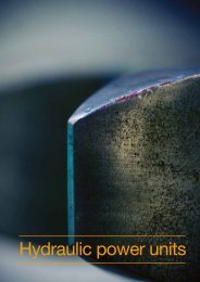
<strong>Aker</strong> 33 <strong>Solutions</strong><br />
<strong>Drilling</strong> Drillfloor <strong>Technologies</strong><br />
equipment<br />
Hydraulic power<br />
units<br />
<strong>Aker</strong> <strong>Solutions</strong> 33<br />
<strong>Drilling</strong> <strong>Technologies</strong>
34<br />
MH hydraulic power unit<br />
> Submerged<br />
pumps<br />
> External pumps<br />
A reliable power source forms the core in every<br />
hydraulic system and is essential to ensure operability<br />
of the various connected equipment and systems.<br />
The industry has been provided with more than 200<br />
MH hydraulic power units (HPU) of different sizes and<br />
configurations during the last decades, spanning from<br />
small single equipment units to large multiple ringline<br />
units, all designed with special focus on reliability,<br />
safety, maintenance and environment.<br />
Key features<br />
The HPU’s are designed for optimum performance,<br />
quality and reliability<br />
All maintenance areas are easily accessible<br />
Submerged (wet) designs are compact increasing<br />
flexibility with respect to installation area<br />
External (dry) designs have external pumps which<br />
are easily maintainable<br />
Working pressure is 207/3000 bar (3,000 psi)<br />
Design pressure is 227 bar (3,290 psi)<br />
<strong>Aker</strong> <strong>Solutions</strong><br />
<strong>Drilling</strong> <strong>Technologies</strong><br />
Hydraulic power units<br />
Technical data<br />
Pump arrangement Submerged The HPU with submerged pump design is a compact design with low<br />
weight and increased flexibility with respect to installation area. The oil<br />
cooler is placed on the HPU.<br />
External The HPU with external pump design allows easy access for maintenance<br />
and service. The oil cooler(s) is (are) located on a separate skid.<br />
Operating zone Safe area HPU for operation in safe area.<br />
Hazardous area HPU for operation in hazardous area.<br />
Cooler type Air oil cooler The air oil cooler is located on the HPU and consists of a radiator cooling<br />
element and an AC motor driven fan. The air cooler is not dependent<br />
on water supply. This makes it easy to install the HPU anywhere on the<br />
platform.<br />
Fresh water cooler The high-performance plate cooler is very efficient with regards to space<br />
requirement and water consumption. The plates are made of stainless steel<br />
(Alloy 316) material.<br />
Sea water cooler The high-performance plate cooler is very efficient with regards to space<br />
requirement and water consumption. The plates are made of titanium<br />
material.<br />
Cooling capacity Normal Plate cooler is sized with a water inlet temperature of max. 32°C (90°F).<br />
Extreme Plate cooler is sized with a water inlet temperature of max. 38°C (100°F).
<strong>Aker</strong> <strong>Solutions</strong><br />
<strong>Drilling</strong> <strong>Technologies</strong><br />
Hydraulic power units<br />
MH hydraulic power unit<br />
Performance - submerged pumps<br />
Number motors ea. Total power kW Capacity (50Hz)<br />
L/min<br />
Options<br />
Pressure transmitter<br />
The pressure transmitter allows remote monitoring of<br />
the HPU supply pressure.<br />
Oil heater<br />
The oil heater consists of a heating element and<br />
junction box located on the oil tank in order to<br />
maintain an oil temperature of 20°C (68°F) in the tank<br />
if the HPU is to be shut down/idle for a period.<br />
Noise protection<br />
The HPU is equipped with noise absorbing cover/<br />
panel(s) around main pump(s) and flexible curtain(s) in<br />
front in order to reduce the noise level.<br />
Capacity (60Hz)<br />
L/min<br />
1 94 220 240 900<br />
2 188 440 480 1500<br />
3 282 660 720 2100<br />
4 376 880 960 3600<br />
5 470 1100 1200 3600<br />
Performance - external pumps<br />
Number motors ea. Total power kW Capacity (50Hz)<br />
L/min<br />
Capacity (60Hz)<br />
L/min<br />
1 94 220 240 1000<br />
2 188 440 480 2200<br />
3 282 660 720 3400<br />
4 376 880 960 4500<br />
5 470 1100 1200 5600<br />
6 564 1320 1440 6700<br />
7 658 1540 1680 7700<br />
Reservoir L<br />
Reservoir L<br />
Noise hood container<br />
The HPU is located inside a noise hood container fully<br />
insulated with perforated zinc-coated sheet inside.<br />
The container is equipped with an AC motor driven fan<br />
which is controlled by an adjustable thermostat preset<br />
to 35°C (95 °F). One of the long sides can be fully<br />
opened in order to maintain the HPU. The container is<br />
designed for outdoor location.<br />
Drip pan<br />
The drip pan is located under the HPU in order to<br />
collect oil spill during service/maintenance.<br />
35
<strong>Aker</strong> 36 <strong>Solutions</strong><br />
<strong>Drilling</strong> <strong>Technologies</strong><br />
Pipe handling<br />
equipment<br />
<strong>Aker</strong> <strong>Solutions</strong> 36<br />
<strong>Drilling</strong> <strong>Technologies</strong>
<strong>Aker</strong> <strong>Solutions</strong><br />
<strong>Drilling</strong> <strong>Technologies</strong><br />
Pipe handling equipment<br />
MH bridge crane<br />
> Typical MH<br />
bridge crane<br />
system<br />
<strong>Aker</strong> <strong>Solutions</strong> has a comprehensive range of vertical<br />
MH pipe handling equipment which can be delivered<br />
as complete systems or individual, tailor made<br />
machines. Typical fingerboard capacity: Up to 550<br />
stands of drill pipe and 14 stands of drill collar.<br />
Key features<br />
The MH bridge crane (BRC) is a part of the pipe<br />
racking system. The pipe racking system forms an<br />
integrated pipe handling system for easier, safer,<br />
and faster handling of tubular on every type of rigs<br />
Designed to lift the stand between the<br />
fingerboards, mousehole and well center<br />
Mounted on or below runway beams in the derrick<br />
above fingerboard level<br />
Can be electronically synchronized with<br />
the lower guiding arm and both run in predefined<br />
paths, thus giving a very simple operators interface<br />
Can alternatively be controlled with an<br />
electrical or hydraulic control stand<br />
Main data<br />
Gripper head Medium-sized Large-sized<br />
Gripper head capacity, min. 2 7/8 in 3 1/2 in<br />
Gripper head capacity, max.<br />
Dimensions<br />
9 3/4 in 14 in<br />
Length (approx.) Depending on runway beam span<br />
Width (approx.) Depending on bridge span<br />
Height (approx.) 11,000 mm (433 in)<br />
Weight Medium-sized Large-sized<br />
Weight (excluding runway beams) 14.2 m.tons (15.7 shT) 30 m.tons (33.1 shT)<br />
Weight, runway beams Depending on runway beam span Depending on runway beam span<br />
37
38<br />
MH 2-arm system<br />
> Upper racking arm<br />
The MH 2-arm system is a derrick mounted pipe<br />
handling system. Typical racking board capacity of the<br />
2-arm system is up to 420 stands of drill pipes and 14<br />
stands of drill collar. Available with and without robotic<br />
motion control (RMC).<br />
Intermediate racking arm<br />
The intermediate racking arm is installed between the<br />
set-backs at approximately 30 ft above the drillfloor.<br />
The arm is telescopic and slewable through approx.<br />
180 degrees, and is mounted on a trolley that travels<br />
in or out in track beams. Designed to lift and guide<br />
drill pipe and drill collars between centre well and<br />
setbacks or vice versa. The rackerhead is mounted<br />
on an approximately 5.5 m (18 ft) long track beam for<br />
vertical guiding during lifting of the stands. The upper<br />
end of the track beam has a guide sheave for the<br />
standlift wireline.<br />
Upper racking arm<br />
The upper racking arm is installed in between the<br />
fingerboards. It is telescopic and slewable through<br />
180 degrees and mounted on a trolley that travels<br />
in and out in track beams. Designed to handle and<br />
guide tubulars up to 9 1/2” o.d. between centre well to<br />
racking boards or vice versa.<br />
<strong>Aker</strong> <strong>Solutions</strong><br />
<strong>Drilling</strong> <strong>Technologies</strong><br />
Pipe handling equipment
<strong>Aker</strong> <strong>Solutions</strong><br />
<strong>Drilling</strong> <strong>Technologies</strong><br />
Pipe handling equipment<br />
MH fingerboard<br />
> MH fingerboard<br />
The MH fingerboard is fully customizable and allows<br />
for the size of the board to be adapted to the available<br />
space. Based on the selected combination of rows for<br />
drill pipes, casing and drill collars tubulars virtually any<br />
setback capacity is attainable – given enough space.<br />
Key features<br />
The MH fingerboard is designed to safely lock<br />
stands in the derrick by a remotely operated<br />
system.<br />
Drill collar stands are fixed in position by an<br />
individual locking finger for each stand. This<br />
prevents the load from the full row of drill pipe<br />
acting on one single locking finger.<br />
Each locking finger is connected to a pneumatic<br />
cylinder by a link mechanism. All bushings are<br />
maintenance free and do not require lubrication.<br />
The operation of the pneumatic cylinder is through<br />
pneumatic valves mounted in the pneumatic power<br />
valve cabinet.<br />
The cylinders are pneumatic operated and have<br />
spring return to close position. The locking fingers<br />
are bolted assemblies with the actuating cylinder<br />
protected within the fingerboard structure. The<br />
polyamide hoses are also well protected, running<br />
inside the fingerboard structure.<br />
In order to simplify the inspection and maintenance<br />
access, the locking finger assemblies are made as<br />
separate units that are accessible from the top<br />
of the fingerboard. The complete locking finger<br />
assembly can be lifted out of fingerboard finger.<br />
The remote control of the fingerboard is integrated<br />
into the control system for the racking machines.<br />
Option: can alternatively be controlled with a<br />
remote electrical panel.<br />
Option: can alternatively be controlled with a<br />
remote pneumatic control panel.<br />
Option: row adapters. In order to use one row<br />
for two or more different OD-sizes, mechanical row<br />
adapters can be added for specific rows.<br />
Option: A special bottom-hole-assembly slot can<br />
be integrated in the fingerboard. This is typically<br />
mounted in a dedicated holder for quick access.<br />
Option: Noise reducing rubber flaps. These wire-<br />
mesh reinforced rubber plates also dampen the<br />
stand movement in fingerboard.<br />
Main data<br />
Dimensions<br />
Depth 1,000 – 10,000 mm (39.4 – 394 in)<br />
Width 1,000 – 10,000 mm (39.4 – 394 in)<br />
Tubular capacity<br />
On a 10x10m fingerboard for quad. stands optimized for one of the following tubular sizes (this calculation assumes only one type of<br />
tubular, the max. capacities cannot be combined). Infinite variations and combinations may be configured.<br />
Max length of 5 1/2” - 5 7/8” drill pipe 176,400 ft (53,800 m)<br />
Max length of 6 5/8” drill pipe 127,710 ft (38,900 m)<br />
Max length of drill collar 66,960 ft (20,400 m)<br />
Max length of casing 95,760 ft (29,200 m)<br />
39
40<br />
MH mousehole<br />
> Telescopic MH<br />
mousehole<br />
>> Standard MH<br />
mousehole<br />
The MH mousehole is highly automated and specially<br />
designed for offline standbuilding of drill pipes,<br />
casings and collars.<br />
Key features<br />
The MH mousehole is suspended from the drillfloor<br />
with a lower support towards the substructure. It is<br />
equipped with a watertight flange. It is hydraulically<br />
powered, supplied from the rig ringline and operated<br />
through a control system from the assistant drillers<br />
chair in driller’s cabin<br />
The portfolio includes both standard and telescopic<br />
type with different lengths and max. tubular<br />
diameters depending on the context of application<br />
The centralizer automatically closes and centralizes<br />
the tubular of different diameters<br />
<strong>Aker</strong> <strong>Solutions</strong><br />
<strong>Drilling</strong> <strong>Technologies</strong><br />
Pipe handling equipment<br />
Main models<br />
Type Standard In principles, a long pipe consisting of main pipe, a “rabbit” with shock absorber and<br />
removable centralizer. The rabbit hoists and lowers the tubular (within the main pipe)<br />
to any desired height needed in the standbuilding operation.<br />
Length 32 ft Standard<br />
Max. tubular diameter<br />
(Pipe dimensions, not tool<br />
joint)<br />
Telescopic The telescopic mousehole is in principles a long pipe consisting “outerbox”, “innerbox”<br />
and a “rabbit”. The main purpose of the telescoping innerbox is to reduce<br />
the mousehole length when retracted for not colliding with the rig structure when the<br />
derrick is skidding or during handling of BOP.<br />
45 ft Standard, telescopic<br />
60 ft Standard, telescopic<br />
9 3/4 in Standard, 32 ft<br />
13 5/8 in Standard, 45/60 ft<br />
20 in Telescopic, 45/60 ft
<strong>Aker</strong> <strong>Solutions</strong><br />
<strong>Drilling</strong> <strong>Technologies</strong><br />
Pipe handling equipment<br />
MH pipe deck<br />
pipe handler<br />
The MH pipe deck pipe handler (PDPH) is located at<br />
pipe deck and its main purpose is to transport tubular<br />
from pipe deck to the MH tubular feeding machine. It is<br />
controlled by a radio remote control panel, either located<br />
in a dedicated chair in drillers control room, or operator<br />
standing outside of drillers control room. The PDPH<br />
have hydraulic oil supply from the rig ring-line system.<br />
Hydraulic hoses are drawn to the PDPH through the<br />
pedestal and electrical cables are connected in the<br />
interface junction box outside the pedestal. Jib cylinders<br />
and gears are operated through the control panel.<br />
When the PDPH is not in use, it shall be parked with<br />
the gripper yoke resting on the deck or in the jib rest<br />
located next to the derrick. This is to be used during<br />
sea voyage, bad weather or when the PDPH will not be<br />
in use for long periods. In addition, there is a parking<br />
position for the yoke, on the heavy tool landing platform.<br />
Main data<br />
Length x width x height 30.9 x 6.4 x 15.2 (m)<br />
Total weight 47770 kg (wo/cabin)<br />
52004 kg (w/cabin)<br />
Design data<br />
Design pressure 207 [3000] Bar [Psi]<br />
Design temp. (amb.) Project specific<br />
Operation temp. (amb.) Project specific<br />
Area classification Safe area/Zone 2<br />
Design category (class) I<br />
Certifying agency (3rd party) standard DNV/ABS<br />
Technical data<br />
Lifting capacity grippers (SWL) 4,5 T. @ 25 m.<br />
Lifting capacity pad eye (SWL) 9,0 T. @ 25 m.<br />
Lifting capacity utility winch (SWL) 5,0 T. @ 25 m.<br />
Maximum load eccentricity ± 0,5 m<br />
Max. working radius 25 m.<br />
Min. working radius 2,6 m.<br />
Slew angle +/- 180º<br />
Slew speed 0,8 rpm<br />
Tubular length Range 2 (30’)<br />
– Range 3 (45’)<br />
Tubular length (min.) 3,5 m.<br />
Tubular diameter 2 7 / 8 ” - 20”<br />
Rotation of gripper +/- 180º<br />
41
42<br />
MH gantry crane<br />
The prime function of the MH gantry crane is to move<br />
drilling tubulars from their storage area to the catwalk<br />
machine and vice versa. The crane is a self-contained<br />
unit with operator’s cabin, hydraulic power unit, power<br />
distribution and control system, all located on the<br />
crane.<br />
Equipped with<br />
2 riser forks for handling riser, pup joints and<br />
casing<br />
2 magnet yokes for handling drill pipes and<br />
other tubulars<br />
Technical data<br />
Lifting capacity (SWL) 2 x 23 mT (2 x 25 tons)<br />
Gantry speed 0.4 m/sec (16.9 in./sec)<br />
Trolley speed 0.25 m/sec (9.84 in./sec)<br />
Hoisting speed 0.25 m/sec (9.84 in./sec)<br />
Max lifting height 11.9 m (39.04 ft.)<br />
Electrical power requirements 3 x 480 VAC 60 Hz (3 x 100 kW)<br />
Total weight 116 mT (128 tons)<br />
<strong>Aker</strong> <strong>Solutions</strong><br />
<strong>Drilling</strong> <strong>Technologies</strong><br />
Pipe handling equipment
<strong>Aker</strong> <strong>Solutions</strong><br />
<strong>Drilling</strong> <strong>Technologies</strong><br />
Pipe handling equipment<br />
MH piperack crane<br />
The MH piperack crane is designed for safe<br />
transportation of tubulars from the pipe deck to<br />
the catwalk machine, and vice versa. The crane is<br />
a cantilever type crane, controlled from a cabin or<br />
platform located on the crane trolley. Remote control<br />
from the drill floor is also available. MH piperack crane<br />
is delivered with twist gripper as handling device.<br />
The control system ensures that the yoke is always<br />
kept horizontal during a sequence. The twist gripper<br />
yoke is designed to pick up tubulars out of centre, but<br />
the load will always be kept horisontal. MH piperack<br />
crane with telescope is mainly used on rigs with small<br />
elevation differences. The telescope increases the<br />
hook up flexibility.<br />
Technical data<br />
Travelling speed 30 m/min (98 ft/min)<br />
Lifting speed 20 m/min (65 ft/min)<br />
Telescopic speed 20 m/min (65 ft/min)<br />
Travelling length 41.3 m (135 ft/min)<br />
Telescopic length 4.6 m (15 ft/min)<br />
Lifting capacity 6.0 mT x 11.4 m (+/- 0.5 m eccentric)<br />
(6.6 tons x 37.4 ft +/- 1.6 ft eccentric)<br />
2.5 mT x 16.0 m (+/- 3m eccentric)<br />
(2.8 tons x 52 ft +/- 10 ft eccentric)<br />
(Distance from center jib)<br />
Tubular length 3.5–14.6 m (11.5–48 ft)<br />
Tubular diameter 2 7/8”–30”<br />
Twist gripper claws 2 7/8”–30”<br />
Installed weight approx. 30 mT (incl. rail, gripper)(33 tons)<br />
43
44<br />
Horizontal to vertical arm<br />
Fast and efficient horizontal to vertical (HTV)<br />
operations with the MH eagle light or MH<br />
standbuilding arm.<br />
Key features<br />
Fast, reliable and safe transfer of tubulars from<br />
a horizontal position at the feeding machine to a<br />
vertical position at either well centre or mouse hole<br />
Minimum requirements for maintenance<br />
Heavy-duty design and a high degree of safety and<br />
durability<br />
Two main models in the portfolio are the MH eagle<br />
light and the MH standbuilding arm. They<br />
provide flexibility and compactness respectively<br />
MH eagle light<br />
Flexible and with a large operational sector<br />
Designed for stabbing casing and tubing and for<br />
building stands while drilling<br />
MH standbuilding arm<br />
Compact yet versatile design<br />
Can traverse two mouse holes of the centre line<br />
Main models<br />
MH eagle light<br />
Flexible HTV operations Compact, medium, large<br />
*or a customized length depending<br />
on customer input<br />
MH standbuilding arm<br />
Optimised for off line<br />
stand building<br />
Performance<br />
One compact size<br />
* From guide rails to centre of tubular in vertical position<br />
Standbuilding arm<br />
SBA fixed size<br />
Approximate reach* 1 m<br />
(3,3 ft)<br />
<strong>Aker</strong> <strong>Solutions</strong><br />
<strong>Drilling</strong> <strong>Technologies</strong><br />
Pipe handling equipment<br />
MH eagle light<br />
Compact Medium Long<br />
2,6-5 m<br />
(8,5-16,2 ft)<br />
2,7-5,4 m<br />
(9,9-17,7 ft)<br />
For all models<br />
Max tubular diameter 20 in (26 in possible with extended yoke)<br />
Max lifting capacity (vertical position) 6,4 m.tons<br />
Max lifting capacity (horizontal to vertical) 3,2 m.tons<br />
Length of tubular stands 4,5 - 14.6 m<br />
(15 – 48 ft)<br />
2,9-5,9 m<br />
(9,4-19,2 ft)
<strong>Aker</strong> <strong>Solutions</strong><br />
<strong>Drilling</strong> <strong>Technologies</strong><br />
Pipe handling equipment<br />
Riser handling system<br />
The riser handling system is a complete solution for<br />
vertical storage and handling of marine riser. The riser<br />
handling crane is designed for vertical handling of<br />
risers from the riser fingerboards to the riser chute<br />
machine where risers are conveyed to the drill floor.<br />
In addition, the crane can be designed to handle and<br />
rack the slip joint. The crane is powered from a rig<br />
main power unit with hydraulic working pressure of<br />
210 bar (3000 psi). Hydraulic and electric power are<br />
supplied by a drag chain, allowing the crane to travel<br />
on rails port/stb. along the fingerboards.<br />
Technical data<br />
Lifting capacity 40 mT (44 tons)<br />
Gantry speed 0.25 m/sec (9.84 in/sec)<br />
Trolley speed 0.25 m/sec (9.84 in/sec)<br />
Hoisting speed 0.1 m/sec (3.9 in/sec)<br />
Lifting height, max. 3.5 m (11.5 ft)<br />
Total weight 74 mT (84 tons)<br />
MH catwalk machine<br />
The MH catwalk machine transfers tubulars between<br />
piperack crane and V-door/drill floor. It is designed<br />
for remote controlled mechanical handling of tubulars<br />
from 2 7/8” to max. 30” outside diameter. Riser and<br />
slip joints are handled by trolleys. The machine can<br />
be delivered with or without feeding arrangements,<br />
tailor-made to suit the actual rig.<br />
Technical data<br />
Range 2 7/8”–30”<br />
Working rate<br />
Drillpipe 40-60 joints/hour<br />
Working pressure 210 bar (3 045 psi<br />
Hydraulic flow Depends on speed and operational<br />
requirements.<br />
Typical 150–300 l/min (40–80 gallon/min)<br />
Size incl. service<br />
platf.<br />
Option: Kit for riser handling.<br />
Typical 1 500x4 000x15 000[mm] (5x13x49 ft)<br />
Weight Varying 20–30 mT (22–33 tons)<br />
45
<strong>Aker</strong> 46 <strong>Solutions</strong><br />
<strong>Drilling</strong> <strong>Technologies</strong><br />
Compensators<br />
and tensioners<br />
<strong>Aker</strong> <strong>Solutions</strong> 46<br />
<strong>Drilling</strong> <strong>Technologies</strong>
<strong>Aker</strong> <strong>Solutions</strong><br />
<strong>Drilling</strong> <strong>Technologies</strong><br />
Compensators and tensioners<br />
MH drill string compensator<br />
MH active heave<br />
compensator<br />
Due to its special design, the top mounted<br />
compensator addresses hook load variations directly<br />
to the crown block. The unique angle approach of the<br />
MH drillstring compensator keeps the vertical force<br />
virtually constant, thereby decreasing weight-on-bit<br />
fluctuations to a minimum.<br />
System<br />
Single unit top structure<br />
Two compensator units (including cylinder,<br />
accumulator and control valve block)<br />
Dual rocker-arm system<br />
Crown block<br />
Air pressure vessels<br />
MH hydraulic power units<br />
Control system<br />
Technical data<br />
Type: 270 - 20 Type: 270 - 25 Type: 454- 908 - 25 Type: 454 - 1135 - 25 Type: 1500 - 2500 -25<br />
Max. compensating 270 mT (595 kips) 270 mT (595 kips) 454 mT (1.000 kips) 454 mT (1.000 kips) 680 mT (1500 KIP)<br />
Max. static load 590 mT (1300 kips) 590 mT (1300 kips) 908 mT (2.000 kips) 1135 mT (2500 kips) 1135 mT (2500 KIP)<br />
Stroke incl. cushioning<br />
zones<br />
Gas volume required<br />
(APV`s)<br />
6.1 m/ (20 ft) 7.62 m/ (25 ft) 7.62 m (25 ft 7.62 m (25 ft) 7.62 m (25 ft)<br />
7 x 1,000 ltr. (265<br />
gal)<br />
8 x 1,000 ltr. (265<br />
gal)<br />
The MH active heave compensator is designed for<br />
installation on semi-submersibles and drillships<br />
with top (crown block) mounted MH drill string<br />
compensator. The active heave cylinder is<br />
mechanically connected to the crown block ensuring<br />
minimum load and relative motion variations. It is<br />
mainly used when landing BOPs, subsea trees, during<br />
under-reaming and during other downhole operations<br />
requiring a minimum of motion. The MH active heave<br />
compensator system enables the passive system to<br />
handle subsea equipment in an extended weather<br />
window. <strong>Drilling</strong> and wire line mode is also available.<br />
13 500 ltr. (6x2250l) 13 500 ltr. (6x2250l 13 500 ltr. (6x2250l)<br />
Max. design pressure 210 bar/3000 (psi) 210 bar/3000 (psi) 207 bar 3000 (psi) 207 bar 3000 (psi) 207 bar 3000 (psi)<br />
Max. design speed<br />
(stroke 5 m)<br />
1.31 m/s 1.31 m/s 1.31 m/s<br />
Technical data<br />
Max. compensating (pull/push) +/- 26 mT<br />
Stroke (inclusive cushioning zones) 7.62 m (25 ft)<br />
Max. design pressure 350 bar 5072<br />
(psi)<br />
Max. design speed (stroke 5m) 1.3 m/s<br />
47
48<br />
MH through tubing<br />
drilling compensator<br />
> MH through tubing<br />
drilling compensator<br />
MH pistontrack<br />
The MH through tubing drilling compensator should<br />
be used when the MH RamRig hoisting system is<br />
running in high speed active compensation mode.<br />
This mode will reduce the MH derrick drilling machine<br />
vertical movement to an estimated ± 20 cm. The<br />
compensator is a passive system, with an adjustable<br />
preload functionality around mid stroke. Movement of<br />
the bottom hole assembly is given directly by the MH<br />
derrick drilling machine position, unless the load is<br />
changed above/below the preload limits.<br />
Sensing the accumulator piston position will increase<br />
safety significantly in virtually all kinds of compensator<br />
systems, enabling warning signals to prevent fatal<br />
failure. <strong>Aker</strong> <strong>Solutions</strong> has developed a patented stand<br />
alone sensor system based on alternating magnetic<br />
fields technology to detect piston position.<br />
Standard sensor applicable for all kinds of<br />
accumulators<br />
Easy to mount, strap on<br />
Minimum rig downtime<br />
Modularised concept<br />
Sensors will normally be supplied in sensor bars of<br />
100 cm length, each with 3 sensor units. One 12mm<br />
cable per sensor bar is connected to the Eex-d<br />
junction box for interfacing to standard industrial<br />
display units. The mounting is strapped on the outside<br />
of the accumulator, using either a steel band or a fibre<br />
band, finalising the mounting by sealing the sensor<br />
off using silicone at the perimeter of the sensor. The<br />
central processing unit can be interfaced to most<br />
industrial standard interfaces. One central processing<br />
unit covers up to 24 sensors in a rack, making it<br />
possible to get semi-continuous measurement when<br />
desired.<br />
<strong>Aker</strong> <strong>Solutions</strong><br />
<strong>Drilling</strong> <strong>Technologies</strong><br />
Compensators and tensioners<br />
Technical data<br />
Length x width x height (oper.) 1 000x67x37 mm<br />
Weight (dry) approx. 5.0 kg (11.0 lb)<br />
Weight (oper.) 5.0 kg (11.0 lb)<br />
Sensor response 6 Hz<br />
Ex-rating Eex-d<br />
Max. wall thickness accu. 60 mm (2.36 in)<br />
IP-grade 68<br />
Max. distance to sensor CPU 15 m (50 ft)<br />
Ex-rating CPU Safe area
<strong>Aker</strong> <strong>Solutions</strong><br />
<strong>Drilling</strong> <strong>Technologies</strong><br />
Compensators and tensioners<br />
Riser tensioners<br />
The riser tensioners utilitise the hydro pneumatic<br />
principle using cylinder with dynamic seal elements<br />
at the cylinder gland and on the accumulator piston.<br />
The cylinder has a low pressure accumulator on the<br />
rodside and features a sling-shot valve. Anti recoil<br />
system and powered deadman drum can be provided.<br />
The riser tensioners can be arranged as single or dual<br />
units.<br />
Following are max tension each unit<br />
Capacities<br />
45 tonnnes (100 kips)<br />
54 tonnes (120 kips)<br />
73 tonnes (160 kips)<br />
91 tonnes (200 kips)<br />
102 tonnes (225 kips)<br />
113 tonnes (250 kips)<br />
Line travel 15.2 m (50 ft)<br />
Line travel 18.3 m (60 ft)<br />
Line travel 19.8 m (65 ft)<br />
MH wireline riser tensioner for<br />
drilling risers<br />
The MH wireline riser tensioner system is installed<br />
on the floating drilling rig to maintain a pre-selected<br />
vertical tension in the riser. When the vessel is heaving<br />
and rolling due to waves, and wind, the wireline<br />
tension system will work as a pre-tensioner spring and<br />
keep tension in the marine riser.<br />
One standard tension system consist of<br />
8 double riser tensioner units with hydralic<br />
snubber drums<br />
8 double idler sheaves<br />
32 working air pressure vessels<br />
9 standby air pressures<br />
2 air control skids<br />
Options<br />
3 air compressor skids<br />
1 fluid fill unit<br />
Main data<br />
Wire travel: 50 feet<br />
Maximum pulling force for each cylinders: 200 KIPS<br />
49
50<br />
MH conductor tensioner<br />
system for drilling risers<br />
The MH conductor tensioner system provides tension<br />
in the conductor and compensates for vertical<br />
conductor motions due to waves, currents, seabed<br />
settlements and temperature expansion.<br />
One tension system consisting of<br />
Four hydraulic tension cylinders<br />
One accumulator skid, consisting of<br />
four hydraulic nitrogen accumulators<br />
One local control panel<br />
Common for all system<br />
Hydraulic power unit<br />
Main data<br />
Stroke: 1125 mm<br />
Maximum pulling force each cylinder: 854 KN<br />
MH direct acting riser<br />
tensioner for drilling risers<br />
Tension capacity up to 5 000 000 lbs<br />
Do not occupy working deck space as traditional<br />
wireline tensioners<br />
Advanced and proven riser anti recoil system<br />
Piston rods made from carbon steel with stainless<br />
steel weld overlay<br />
Can be integrated with a trip saver<br />
Low weight and low centre of gravity<br />
Designed to operate with two cylinders out of<br />
operation<br />
Maintenance work reduced to a minimum due to<br />
few moving parts<br />
<strong>Aker</strong> <strong>Solutions</strong><br />
<strong>Drilling</strong> <strong>Technologies</strong><br />
Compensators and tensioners
<strong>Aker</strong> <strong>Solutions</strong><br />
<strong>Drilling</strong> <strong>Technologies</strong><br />
Compensators and tensioners<br />
Other tensioners<br />
<strong>Aker</strong> <strong>Solutions</strong> provides all kinds of tensioners for<br />
drilling rigs, including guideline tensioners, podline<br />
tensioners and utility tensioners, including winches<br />
behind the tensioners.<br />
Technical data<br />
7.3 tonnes (16 kips)<br />
11.3 tonnes (25 kips)<br />
Line travel 12.2 m (40 ft)<br />
Line travel 15.2 m (50 ft)<br />
51
<strong>Aker</strong> 52 <strong>Solutions</strong><br />
<strong>Drilling</strong> <strong>Technologies</strong><br />
<strong>Drilling</strong> risers<br />
<strong>Aker</strong> <strong>Solutions</strong> 52<br />
<strong>Drilling</strong> <strong>Technologies</strong>
<strong>Aker</strong> <strong>Solutions</strong><br />
<strong>Drilling</strong> <strong>Technologies</strong><br />
<strong>Drilling</strong> risers<br />
<strong>Drilling</strong> risers<br />
Enhanced technology for drilling wells in the world’s<br />
deepest waters.<br />
<strong>Aker</strong> <strong>Solutions</strong> offers complete deep water marine<br />
riser systems. Being at the forefront of deepwater<br />
offshore riser technology we offer a full range<br />
of drilling riser solutions, including associated<br />
equipment.<br />
Deep water CLIP riser for<br />
marine drilling operations<br />
Features<br />
The main features of the CLIP riser connector are<br />
minimised stress concentrations, excellent connector<br />
fatigue resistance and optimal profile design and steel<br />
quality.<br />
The CLIP Riser features include the most secure<br />
connection with fully opened or fully closed positions<br />
and eliminates the need for threading, bolting and<br />
preloading. This safe and reliable operation allows for<br />
hang off during bad weather and a very high strengthto-weight<br />
ratio.<br />
The Clip riser, which has been proven in deep water<br />
without failure, has a simple trouble free design and<br />
a long life service due to its high fatigue resistance<br />
reducing the need for maintenance dramatically. Other<br />
benefits include field-proven shortest tripping time, lip<br />
seals including anti-extrusion rings, field replaceable<br />
peripheral lines for upgrading and replaceable pins<br />
with these peripheral lines. Easy stabbing can also be<br />
achieved even if misaligned.<br />
A key feature of our drilling riser is the Deep water<br />
CLIP riser connector technology, a unique system<br />
developed and patented by Institut Français du<br />
Pétrole (IFP). Time and cost savings include:<br />
Connection can be made up in less than 11<br />
seconds<br />
Significant time savings in deep waters compared<br />
to conventional connectors reducing tripping time<br />
by hours and up to several days in ultra-deep<br />
water<br />
Reduced manpower requirements<br />
Safer operation involving less people with simpler<br />
tools<br />
53
54 <strong>Aker</strong> <strong>Solutions</strong><br />
<strong>Drilling</strong> <strong>Technologies</strong><br />
<strong>Drilling</strong> risers
<strong>Aker</strong> 55 <strong>Solutions</strong><br />
<strong>Drilling</strong> <strong>Technologies</strong><br />
BOP handling<br />
equipment<br />
<strong>Aker</strong> <strong>Solutions</strong> 55<br />
<strong>Drilling</strong> <strong>Technologies</strong>
56<br />
MH BOP handling system<br />
> MH BOP<br />
transporter<br />
>> MH BOP<br />
trolley<br />
MH BOP transporter<br />
The BOP forklift transporter can be used for a two<br />
stack system with the main frame design allowing a<br />
skidding system to be adopted for placing the BOP<br />
stack(s) alongside the transporter on the cellar deck<br />
storage area. Capacities for the equipment range from<br />
170mT to 400 mT (187 - 440 tons) with lifting heights<br />
from 3.0 m to 10.0 m (10 - 33 ft).<br />
The BOP trolley allows the stack to be transported<br />
from the parked position to the well centre along the<br />
moonpool or vice versa and is generally used together<br />
with an overhead crane of the same capacity as the<br />
trolley to allow the stack to be lifted to the storage<br />
position.<br />
<strong>Aker</strong> <strong>Solutions</strong><br />
<strong>Drilling</strong> <strong>Technologies</strong><br />
BOP handling equipment<br />
The MH BOP handling system is designed to suit<br />
the customer’s requirements/rig limitations, is tailormade<br />
to any specification and built from one or more<br />
standard products:<br />
BOP transporters/trolleys<br />
Subsea tree transporters/trolleys<br />
Overhead cranes<br />
Baseplate trolleys<br />
Skidding systems<br />
Over/underhull guiding systems<br />
Upon receipt of information we can give a system<br />
proposal, and suggest additions that can be made<br />
to give the most efficient handling system. Systems<br />
can be delivered with capacities up to 400 mT (440<br />
tons). The prime function of the BOP/subsea tree<br />
handling systems is to safely transport, lift or guide the<br />
equipment from the parked or storaged position to the<br />
well centre, or vice versa.
<strong>Aker</strong> <strong>Solutions</strong><br />
<strong>Drilling</strong> <strong>Technologies</strong><br />
BOP handling equipment<br />
MH overhead crane/<br />
MH gantry crane<br />
MH BOP guide system<br />
MH base plate trolley<br />
The MH overhead crane/MH gantry crane are<br />
designed to suit the clients’ requirements and are<br />
available both as electric and hydraulic cranes. The<br />
latter option includes an onboard power unit. Most<br />
units can be designed with transverse travel. The<br />
controls are usually cabin mounted or pendant. The<br />
MH gantry crane can be delivered with capacities<br />
ranging from 5.5mT (0.1 tons) to 250mT (275 tons).<br />
The guide systems provide guidance and horizontal<br />
restraint for the BOP when being lifted by the<br />
drawworks. Guide systems can be adapted to either<br />
transporter or overhead crane systems, and mounted<br />
on deck, under deck, or connected to the transporter.<br />
The systems can be fixed, hinged or sliding. Both<br />
conventional tube spear type systems and rubber<br />
buffer roller type systems are available.<br />
The MH base plate trolley is designed as auxiliaries<br />
to most systems, and the main function is to handle<br />
temporary and permanent guide bases. The trolleys<br />
are strong enough to support the lower marine riser<br />
package. Their unique design allows the unit to enter<br />
within the guide lines, making trolleys ideal as a<br />
service platform at the drill string centre. The trolleys<br />
can be adapted for handling BOPs and subsea trees<br />
with capacities ranging from 30 mT to 300 mT (33 -<br />
330 tons).<br />
57
<strong>Aker</strong> 58 <strong>Solutions</strong><br />
<strong>Drilling</strong> <strong>Technologies</strong><br />
<strong>Drilling</strong> fluid<br />
equipment<br />
<strong>Aker</strong> <strong>Solutions</strong> 58<br />
<strong>Drilling</strong> <strong>Technologies</strong>
<strong>Aker</strong> <strong>Solutions</strong><br />
<strong>Drilling</strong> <strong>Technologies</strong><br />
<strong>Drilling</strong> fluid equipment<br />
Wirth mud pumps<br />
> Wirth HP mud<br />
pump TPK 2200<br />
- gear driven<br />
> Wirth HP mud<br />
pump with a<br />
water jacket<br />
motor<br />
> Wirth hydraulic<br />
quick release<br />
We offer a full line of triplex high pressure mud pumps<br />
to handle any drilling requirements. These tough<br />
field proven models cover input horsepower ratings<br />
between 800 to 2 200. These are available with rear<br />
or top mounted, belt, chain or gear driven, AC or DC<br />
drive motor configurations with an operating pressure<br />
between 5 000 up to 7 500 PSI.<br />
Main features<br />
Optimal smoothness of operation<br />
Compact design, less weight<br />
Pump drive units for permanent-load operation,<br />
with a high degree of stability<br />
Gear wheels and drive shaft of wear-resistant heat<br />
treated steel<br />
Hydraulic quick release system<br />
Independent lubrication system<br />
High lifetime on consumables items<br />
Surveillance and control elements for early<br />
recognition of failures<br />
Full material traceability as standard<br />
Fluid ends in stainless steel (optional) for increased<br />
lifetime<br />
Gear driven mud pump TPK 2 200<br />
Replacing chain or belt driven systems<br />
Powered by single top mounted AC motor 2 200 HP<br />
Higher lifetime<br />
Reduced maintenance work<br />
Lower service costs<br />
Less vibration<br />
Lower noise emission<br />
The gear-driven high pressure mud pump (type<br />
TPK) is the most compact design, powered by a<br />
state of the art AC water jacket motor solution.<br />
Advanced features of the water jacket motor<br />
solution include:<br />
Lower noise emission (< 83 dBa)<br />
Protection against corrosion<br />
Reduced height (approximately 400 mm)<br />
IP 56 as standard, Ex-d and ATEX as option<br />
Triplex mud pumps feature a hydraulic quick<br />
release system<br />
For safe and easy maintenance of:<br />
Valve replacement and hydraulic valve closure<br />
Liner and piston replacement<br />
Fluid end modules replacement<br />
Originally patented by <strong>Aker</strong> Wirth GmbH the features<br />
are available as either premium or classic line options.<br />
The hydraulic system is an important element with<br />
respect to safe, effective and easy maintenance of<br />
these features.<br />
59
60<br />
Wirth mud pumps<br />
> Wirth HP mud<br />
pumps TPK 1600<br />
- belt driven<br />
Product lines<br />
Wirth mud pumps are available in two different<br />
product lines. The exact specifications of the<br />
product depends on customer requirements. Proven,<br />
standardised products characterise the “classic line”<br />
mainly used for onshore applications. The product<br />
of the “premium line” guarantees the highest quality<br />
and a tailor-made solution to suit all customer<br />
requirements.<br />
Mud pumps TPK<br />
7 1/4“ x 8<br />
1/2”<br />
800 - 100<br />
Discharge flow max. l/min<br />
US gall. p.m<br />
Operating pressure max. bar<br />
PSI<br />
Input power requirements kW<br />
hp<br />
2 761<br />
730<br />
345<br />
5 000<br />
597/746<br />
800/1 000<br />
<strong>Aker</strong> <strong>Solutions</strong><br />
<strong>Drilling</strong> <strong>Technologies</strong><br />
<strong>Drilling</strong> fluid equipment<br />
Premium line<br />
State-of-the-art equipment<br />
Complying to the highest offshore standards<br />
Including all features to provide the customer with<br />
a superior product<br />
Tailor-made to best suit customer requirements<br />
Classic line<br />
State-of-the-art equipment<br />
Complying to onshore standards<br />
Features are optional<br />
100 percent standardised product<br />
TPK<br />
7“ x 10”<br />
1300<br />
2 838<br />
750<br />
345<br />
5000<br />
969<br />
1 300<br />
TPK<br />
7 1/2“ x<br />
12”<br />
1600<br />
3 127<br />
826<br />
345<br />
5 000<br />
1 193<br />
1 600<br />
TPK<br />
7 1/2“ x 12”<br />
1600<br />
3 127<br />
826<br />
517<br />
7 500<br />
1 193<br />
1 600<br />
TPK<br />
7 1/2“ x 12”<br />
2000<br />
3 127<br />
826<br />
517<br />
7 500<br />
1 491<br />
2 000<br />
Input number of revolution min 1 626 594 484 484 475 436<br />
No. of strokes max. min 1 160 150 120 120 120 110<br />
Dry weight excluding drive kg<br />
lbs<br />
Dimensions L mm<br />
inch<br />
W mm<br />
inch<br />
H mm<br />
inch<br />
17 500<br />
38 587<br />
3 810<br />
150<br />
2 414<br />
95.0<br />
2 300<br />
90.6<br />
2 100<br />
46 305<br />
4 280<br />
168.5<br />
2 645<br />
104.1<br />
2 410<br />
94.9<br />
23 500<br />
51 817<br />
4 610<br />
181.5<br />
2 860<br />
112.6<br />
2440<br />
96.1<br />
24 500<br />
54 013<br />
4 610<br />
182.5<br />
2 873<br />
113.1<br />
2 500<br />
98.4<br />
33 000<br />
72 765<br />
4 910<br />
193.3<br />
2 925<br />
115.2<br />
2 745<br />
108.1<br />
TPK<br />
7 1/2 “ x<br />
14”<br />
2200<br />
3 348<br />
885<br />
517<br />
7 500<br />
1 640<br />
2 200<br />
36 000<br />
79 380<br />
5 220<br />
205.5<br />
2 925<br />
115.2<br />
2 745<br />
108.1
<strong>Aker</strong> <strong>Solutions</strong><br />
<strong>Drilling</strong> <strong>Technologies</strong><br />
<strong>Drilling</strong> fluid equipment<br />
STEP mud mixing and<br />
treatment equipment<br />
> STEP liquid<br />
chemical skid w/VFD<br />
pumps<br />
> STEP sack<br />
cutting unit<br />
> STEP mud<br />
mixing skid<br />
>> STEP mud<br />
hopper<br />
<strong>Drilling</strong> fluid (mud) equipment<br />
<strong>Aker</strong> <strong>Solutions</strong> supplies high quality systems for<br />
drilling fluid applications.<br />
STEP mud mixing equipment<br />
Sack cutting units<br />
Lifting tables<br />
Mud hoppers<br />
Liquid chemical skids<br />
Barrel holders<br />
Rapid barite mixers<br />
Caustic mixing units<br />
HP shear units<br />
LP shear units<br />
Big bag units<br />
Centrifugal pumps<br />
Bulk surge tanks<br />
Surge tank feeders<br />
STEP treatment equipment<br />
Degassers<br />
Agitators<br />
Mud guns<br />
Tank cleaning machines<br />
Chemical injection units<br />
61
62<br />
> STEP operator<br />
station<br />
> STEP surge tank<br />
feeder<br />
> STEP bulk<br />
storage tank<br />
> STEP delta, rock<br />
catcher and Ys<br />
>> STEP dust<br />
cyclone and<br />
collector<br />
>>> STEP bulk surge<br />
tank<br />
<strong>Aker</strong> <strong>Solutions</strong><br />
<strong>Drilling</strong> <strong>Technologies</strong><br />
<strong>Drilling</strong> fluid equipment<br />
STEP control systems and interfaces<br />
automated processes<br />
Heave/tilt panels<br />
Auto density<br />
Auto bulk transfer<br />
Auto mud transfer<br />
Monitoring, start/stop of equipment<br />
Centrifuge control<br />
Instrumentation and monitoring<br />
Automated valves<br />
Density signals from pits and mixing lines<br />
Pressure signals from pumps and bulk storage<br />
tanks<br />
Hi level switches<br />
Level transmitters in mud pits and storage tanks<br />
Load cell signals<br />
STEP solids control equipment<br />
Gumbo conveyors<br />
Flow dividers<br />
Shale shakers<br />
Desanders<br />
Desilters<br />
Mud cleaners<br />
Screw conveyors<br />
Centrifuges<br />
Cuttings dryers<br />
Cuttings transport<br />
Slurrification units<br />
Cuttings re-injection<br />
STEP bulk equipment<br />
Bulk storage tanks<br />
Rock catchers<br />
Dust cyclone and collectors<br />
Pressure reducing stations<br />
Sampling units<br />
Supply vessel bulk systems
<strong>Aker</strong> 63 <strong>Solutions</strong> <strong>Drilling</strong> equipment<br />
<strong>Drilling</strong> <strong>Technologies</strong><br />
Handling tools<br />
<strong>Aker</strong> <strong>Solutions</strong> 63<br />
<strong>Drilling</strong> <strong>Technologies</strong>
64<br />
MH drill pipe elevator<br />
> MH drill pipe<br />
elevator<br />
> MH power slips<br />
frame for drill pipe<br />
slips 3”-7”<br />
The MH drill pipe elevator is DnV type approved and<br />
designed in accordance with API specifications.<br />
The well proven MH drill pipe elevator is pneumatically<br />
operated.<br />
5” - rated to 350 tons - weight 550 kg (1220 lb)<br />
3 ½” - rated to 350 tons - weight 570 kg (1270 lb)<br />
MH power slips frame<br />
The MH power slips frame lifts ordinary drill pipe<br />
slips in and out of the rotary table. The frame pushes<br />
the slips down on the rotary table during operation.<br />
It rotates with the rotary table, but when more than<br />
one revolution is required, the hoses have to be<br />
disconnected. The hoses are connected to the<br />
cylinder with quick-disconnect couplings. The MH<br />
power slips frame is operated by a pedal, being<br />
placed in the driller’s house or somewhere else on<br />
the drill floor, with clear vision of the rotary table.<br />
For pneumatic power slips frames, the arm has the<br />
capability to lift maximum two times the weight of the<br />
slips (approx. 200 kg) with a pressure of 7 bar (100<br />
psi).<br />
Main data<br />
Dimensions Pneumatic version Hydraulic version<br />
Length 1,400 mm (55.1 in) 1,400 mm (55.1 in)<br />
Width 600 mm (23.6 in) 600 mm (23.6 in)<br />
Height<br />
Weight<br />
700 mm (27.6 in) 700 mm (27.6 in)<br />
Dry weight 160 kg (353 lb) 160 kg (353 lb)<br />
Operating weight<br />
Capability<br />
160 kg (353 lb) 160 kg (353 lb)<br />
Fit master bushing size 27 ½” - 37 ½” - 49 ½” - 60 ½” 27 ½” - 37 ½” - 49 ½” - 60 ½”<br />
Adapter to fit slips for DP size, min. 3 1/2 in 3 1/2 in<br />
Adapter to fit slips for DP size, max. 7 in. 7 in.<br />
<strong>Aker</strong> <strong>Solutions</strong><br />
<strong>Drilling</strong> <strong>Technologies</strong><br />
Handling tools
<strong>Aker</strong> <strong>Solutions</strong><br />
<strong>Drilling</strong> <strong>Technologies</strong><br />
Handling tools<br />
Wirth hydraulic rotary table<br />
Wirth rotary tables are field proven, efficient and<br />
reliable. Two major model ranges are available: the<br />
traditional, independent electric rotary tables for<br />
conventional applications, and the more common<br />
hydraulic rotary tables for rigs fitted with top-drives.<br />
Hydraulic rotary tables type RTSS-H are available<br />
with openings from 27 1/2” to 75 1/2” and static<br />
load ratings up to 1 250 tons.<br />
This type uses a hydraulic motor directly connected<br />
to the rotary drive gear, thus eliminating transmission<br />
and drive train, which results in smaller,<br />
lighter and more cost-effective design.<br />
High torque and variable speed<br />
Designed for high load<br />
Combined axial roller ball-bearing<br />
Less weight and reduced skid size<br />
Lower maintenance cost<br />
Hydraulic locking device<br />
External hydraulic control station for<br />
easy maintenance<br />
Independent centralised lubrication system<br />
to optimise lifespan<br />
Suitable for installation of various power slips<br />
Split adapter 49 1/2” to 37 1/2”<br />
Adapter 60 1/2” to 49 1/2”<br />
Optional: integrated rails for various iron<br />
roughneck types<br />
65
66<br />
Wirth electric-driven<br />
rotary table<br />
Electric rotary tables type RTSS-E are available with<br />
openings from 27 1/2” to 49 1/2” and static load<br />
ratings up to 800 tons.<br />
The independent rotary drive eliminates the necessity<br />
of selecting a drawworks transmission ratio to obtain<br />
the desired speed for both pumps and rotary.<br />
The installed two-speed transmission is suitable for<br />
use with either DC or AC drilling motors up to 1 000 hp<br />
at 1 200 rpm class with an output rating of high torque<br />
capacity.<br />
<strong>Aker</strong> <strong>Solutions</strong><br />
<strong>Drilling</strong> <strong>Technologies</strong><br />
Handling tools<br />
Features<br />
High performance<br />
Designed for high torque and high load<br />
Double row ball thrust bearing<br />
Mechanical locking device<br />
Two-speed transmission design includes helical<br />
gears, spline clutches, shifter lock mechanism,<br />
roller bearing and independent lubrication system<br />
with cooling system<br />
For use with DC or AC drilling motors up to<br />
1 000 hp<br />
Split adapter 49 1/2” to 37 1/2”<br />
Additional pipe handling equipment suitable for all<br />
rotary tables, e.g. master bushings, insert bowls,<br />
split casing bushings, reducing bushings,
<strong>Aker</strong> 67 <strong>Solutions</strong><br />
<strong>Drilling</strong> <strong>Technologies</strong><br />
Personnel lifting<br />
<strong>Aker</strong> <strong>Solutions</strong> 67<br />
<strong>Drilling</strong> <strong>Technologies</strong>
68<br />
MH access basket<br />
The MH access basket is designed for safe access<br />
when performing maintenance and/or working tasks<br />
in places that are hard to reach. The basket can easily<br />
be installed in the derrick, moonpool area or other<br />
areas, either directly with the mounting bracket, or by<br />
means of various optional interface kits.<br />
All the basket controls, including emergency stops,<br />
can be operated from inside the basket and/or remote<br />
control stand:<br />
Special version can be delivered for BOP or subsea<br />
tree operations<br />
Rail mounting<br />
180 degrees rotation<br />
Technical data<br />
Maximum free working height 17.2m (56.4 ft)<br />
Maximum permitted load 300 kg (660 lb)<br />
Hydraulic power<br />
207 bar, 50 l/min<br />
consumption<br />
(3 000 psi/13 gal./min)<br />
Tilting, up/down +- 60 degrees<br />
Rotating +- 90 degrees<br />
Max. weight 4000 kg (8800 lb)<br />
Telescoping 3 400 mm (11.2 ft)<br />
4 600 mm (15.1 ft)<br />
5 600 mm (18.4 ft)<br />
The access basket can be supplied with one or two-man basket.<br />
Main models<br />
Reach Compact (8.6 m)/medium<br />
(10.4 m)/long (11.9 m)<br />
Capacity 1 man or 2 man basket<br />
Dual rotation Up to 60 degrees rotation of the<br />
working platform relative to<br />
telescopic arm<br />
<strong>Aker</strong> <strong>Solutions</strong><br />
<strong>Drilling</strong> <strong>Technologies</strong><br />
Personnel lifting
<strong>Aker</strong> <strong>Solutions</strong><br />
<strong>Drilling</strong> <strong>Technologies</strong><br />
Personnel lifting<br />
MH casing stabbing board<br />
The MH casing stabbing boards are designed for<br />
safe travel within the drilling structure and have long<br />
standing, proven environments encompassing the<br />
globe. The MH casing stabbing board has a monorail<br />
track, which provides smoother carriage travel,<br />
better visibility and a greater freedom of movement,<br />
promoting efficiency of the rig. The boards are<br />
adjustable from 23 feet to 47 feet above the drill<br />
floor and are designed to be mounted in a customer<br />
specified location. The design allows for the carriage<br />
to be manually locked into any position for added<br />
safety.<br />
Casing stabbing boards come with an ABS man riding<br />
certified winch with two automatic brakes to control<br />
travel. A deadman type control stops carriage travel<br />
when the operator releases the safety pull-cord. A<br />
dual over-speed device stops the carriage in the event<br />
of wireline failure. The casing stabbing board includes<br />
a full body harness which attaches to a retractable<br />
overhead safety block by cable. Space requirements<br />
for the system are reduced by the counterweight<br />
carriage platform that folds to storage position when<br />
not in use. The carriage platform provides a safe place<br />
for the operator to stand when the carriage is in the<br />
stored position.<br />
Features<br />
Mono-rail track provides smoother carriage travel,<br />
better visibility, and greater movement<br />
Adjustable from 23’-0” to 47’-0” above drill floor<br />
Designed to be mounted at customer specified<br />
location<br />
Design allows carriage to be manually locked into<br />
any position for added safety<br />
Two (2) automatic brakes, air powered release,<br />
spring set<br />
Two (2) automatic over speed safety devices set<br />
One (1) ton man riding air winch; complete with air<br />
control valve<br />
Deadman type control; when operator releases<br />
safety pull-cord, carriage travel stops<br />
Carriage travel can be operated from drill floor<br />
Carriage platform access from the drillfloor via<br />
ladder<br />
Counterweighted carriage platform folds into<br />
storage position while not in use<br />
Upper and lower stops limit carriage travel<br />
Retractable overhead safety block attaches to<br />
operator’s full body harness<br />
69
<strong>Aker</strong> 70 <strong>Solutions</strong><br />
<strong>Drilling</strong> <strong>Technologies</strong><br />
<strong>Drilling</strong> control<br />
and monitoring<br />
systems<br />
<strong>Aker</strong> <strong>Solutions</strong> 70<br />
<strong>Drilling</strong> <strong>Technologies</strong>
<strong>Aker</strong> <strong>Solutions</strong><br />
<strong>Drilling</strong> <strong>Technologies</strong><br />
<strong>Drilling</strong> control and monitoring systems<br />
<strong>Drilling</strong> control and monitoring<br />
systems<br />
A key element on a modern drilling rig is the control<br />
system. <strong>Aker</strong> <strong>Solutions</strong> is one of the largest suppliers<br />
of state-of-the-art drilling control and monitoring<br />
systems (DCMS). The building blocks and main<br />
features of these systems are:<br />
Local equipment controls/PLCs<br />
MH DrillView TM , data acquisition, presentation and<br />
control system<br />
MH configurable automatic drilling system (CADS)<br />
Necessary computer hardware<br />
<strong>Drilling</strong> control cabins (DCCs)<br />
All the delivered equipment and third party equipment;<br />
i.e. drawworks, mud pumps, cementing unit, mud<br />
logger, mud control and BOP can be integrated<br />
into the DCMS and be monitored and/or controlled<br />
from the DCC. The DCMS is designed and<br />
manufactured according to industry standards and<br />
the highest standards related to HSE and humanmachine<br />
interface. The MH DrillView TM system can<br />
accommodate any level of automation;<br />
Remote control of equipment/systems<br />
Synchronisation of various equipment<br />
Fully automatic mode<br />
Fully automatic mode with synchronised CCTV<br />
operation and predefined drilling operation<br />
sequences (CADS)<br />
MH DrillView TM overview<br />
Operators control room<br />
Soft torque<br />
E-tally MH systems<br />
DrillView system<br />
CCTV <strong>Drilling</strong> recorder Drillers assist<br />
The configurable automatic drilling system (CADS)<br />
was developed to create a user-friendly and superior<br />
control system with respect to efficiency and safety.<br />
The result is a highly flexible and user configurable<br />
system, accessible for the drilling contractor’s<br />
personnel for on site adoptions. The system includes<br />
predefined drilling operator sequences, thereby<br />
standardising operations and improving safety. Safe<br />
operation is an integral part of the system with smart<br />
zone managment system. Necessary set-points,<br />
interlocks, anti-collision, fully automated CCTV<br />
controls and other safety features are built into the<br />
software. The MH DrillView TM /CADS system is based<br />
on touch screens and a state-of-the-art computer<br />
system.<br />
In order to reduce testing time on site, and ensure<br />
timely delivery, we integrate equipment tests with<br />
tests on the DCMS and operator’s chair. Prior to<br />
testing on site, the drilling control monitoring system<br />
(MH DrillView TM ) and operator’s chair are tested in<br />
the laboratory by means of simulation. During this<br />
extensive testing, we may give practical equipment<br />
training of the customer’s operators and service<br />
personnel.<br />
DrillView<br />
clients and reports<br />
Router to<br />
onshore<br />
CADS<br />
Mud logger – MWD – RMS – DMPCS – Mud control – CCS – WL – CTU<br />
71
72<br />
MH operator chair<br />
MH E-tally<br />
To enable active operator support, a fully integrated<br />
workstation with integrated closed circuit television<br />
station (MH CCTV) may be established in an onshore<br />
operation center. Design according to ergonomic<br />
standards offer a good working environment for the<br />
operator.<br />
Key features<br />
The MH operator chair is designed either<br />
for remote control of single or multiple drillfloor<br />
equipment.<br />
Extensive use of touch screen technology well-<br />
coordinated with joystick control.<br />
The advanced operator chair with full multi-user<br />
selection between different drilling operation<br />
modes and efficient/rapid installation due to “plug<br />
in” design.<br />
The compact operator chair is designed for<br />
operation in Zone 2 (hazardous area)<br />
The electronic tally book system keeps track of all<br />
items passing through the V-door and it does not<br />
require any tagging of the pipe. The system uses the<br />
length measuring capabilities of the tubular feeding<br />
machine. The operator must give input regarding the<br />
pipe type. From this information the system calculates<br />
all information needed to replace the conventional tally<br />
book. In addition the E-tally system keeps track of the<br />
pipe’s location inside the fingerboard or its position in<br />
the drill string. The system is also capable of tracing<br />
casing.<br />
<strong>Aker</strong> <strong>Solutions</strong><br />
<strong>Drilling</strong> <strong>Technologies</strong><br />
<strong>Drilling</strong> control and monitoring systems<br />
Main models and data<br />
Main model Hazardous area Location Multiple and<br />
Min. swing Estimated<br />
single operation radius (mm) weight (kg)<br />
Advanced operator chair Safe area Control cabin Multiple 650 190<br />
Compact operator chair Safe area Small cabin Single 668 100<br />
Compact operator chair Safe area Small cabin Multiple 668 100<br />
Compact operator chair Safe area - Zone 2 Small cabin Single 675 80
<strong>Aker</strong> <strong>Solutions</strong><br />
<strong>Drilling</strong> <strong>Technologies</strong><br />
<strong>Drilling</strong> control and monitoring systems<br />
MH DrillView<br />
> MH DrillView TM<br />
with integrated<br />
CCTV<br />
>> Typical<br />
system detail<br />
picture; shown<br />
here is the MH<br />
HTV mode<br />
picture<br />
Get your rig connected<br />
The MH DrillView TM system provides a user<br />
friendly interface for acquisition, logging, storage,<br />
distribution and display of drilling data, as well as<br />
set-up and remote control of drilling equipment. MH<br />
DrillView TM integrates your drilling systems into one<br />
common control and monitoring centre. Real time<br />
drilling data can be shared between the driller, rig<br />
offices, shorebase or other locations accessible by<br />
telecommunications.<br />
Integration in practice<br />
Based on drilling operational experience, the system<br />
offers a completely integrated platform designed<br />
for the entire drilling rig. User friendly screen<br />
arrangements cover all normal drilling operations,<br />
such as drilling, tripping, mud system storage,<br />
mudlogger interface and circulation, kicks, string<br />
and hole data, make-up torque logs and others.<br />
The user can monitor the status of the individual<br />
drilling equipment via “equipment status screens”.<br />
These form the basis for efficient trouble shooting,<br />
or planning of maintenance. Information is easily<br />
accessible due to the system’s versatility and<br />
flexibility. The user can easily set up trend charts from<br />
a large selection of direct and computed variables.<br />
All data stored from previous wells can be replayed<br />
for analysis, and all drilling data is available for off<br />
line reports using standard office tools like Microsoft<br />
Access or Excel. The drilling data is stored in an SQL<br />
real time database. A central alarm system provides<br />
the rig with distributed status information.<br />
Industry standard basis<br />
The MH DrillView TM system is based on a number<br />
of industrial-type workstations in a client/server<br />
environment. Field level interface (sensors, actuators,<br />
and other automation systems) is by programmable<br />
logic controllers (PLCs), normally in a profibus type<br />
network.<br />
Web server integrated<br />
The MH DrillView TM system has a built in web server,<br />
which means that all data can be made available on<br />
the LAN/WAN/Internet as read only or full control<br />
instantly.<br />
Interface your drilling equipment<br />
MH DrillView TM contains all the mechanisms required<br />
to interface with drilling equipment for control<br />
purposes. Typical examples are control of pumps<br />
and valves on mud system schematics, control of<br />
hydraulic power units, control and priority setting of<br />
starters, assignment of SCRs and others.<br />
Scaleable<br />
MH DrillView TM is designed to suit all levels of<br />
complexity, from systems with small sensor package<br />
and one workstation, to large drilling control<br />
systems with multiple sensors, control systems,<br />
communication links, workstations and users.<br />
Decision support, trend monitoring, advanced<br />
alarms, interfaces, drilling data management, drilling<br />
equipment control, data distribution, easy to use and<br />
good graphics are keywords for a good drilling data<br />
system. MH DrillView TM covers these requirements.<br />
The MH DrillView TM system can be delivered to rigs<br />
independent of additional drilling equipment, and it is<br />
designed to facilitate interface between various types<br />
of equipment.<br />
73
74<br />
MH CCTV<br />
> MH dome CCTV<br />
camera with wall<br />
bracket, sunshield<br />
and wash/dry unit<br />
> System with<br />
analogue and digital<br />
The MH CCTV system (CCTV) gives an overview<br />
of the operation being performed and the area of<br />
operation. The drilling cameras of the CCTV system<br />
support the drilling operator in safe operation of the<br />
machines and give live TV picture coverage of the<br />
critical functions in the drilling sequence. All drilling<br />
cameras are ATEX approved.<br />
In addition to the drilling cameras, we deliver marine<br />
cameras for video surveillance of the topside/marine<br />
areas as a part of the CCTV system. The system<br />
utilizes the newest CCTV technologies; including<br />
MPEG-4 for video transmission.<br />
Main cubicle<br />
This cubicle contains all required terminals, power<br />
supplies, fuses, network equipment and a complete<br />
CCTV server; a super micro computer with Milestone<br />
CCTV software installed. The cubicle is classified for<br />
use in a safe area.<br />
<strong>Aker</strong> <strong>Solutions</strong><br />
<strong>Drilling</strong> <strong>Technologies</strong><br />
<strong>Drilling</strong> control and monitoring systems<br />
The CCTV equipment may be installed in a separate<br />
cubicle, or installed as part of another cubicle (e.g. the<br />
drilling FTP cubicle).<br />
Application software package for CCTV server<br />
Milestone XProtect Enterprise provides a state-of-theart<br />
IP video surveillance system, supporting the widest<br />
choice of network cameras and video servers, with<br />
the equipment connected to an office LAN or other<br />
TCP/IP network. All video will be stored on harddisk<br />
for a configurable number of days.<br />
The optional MH Matrix Server and Panasonix SX650<br />
Matrix Switcher make it possible to view analog video<br />
from drilling cameras.<br />
Application software package for HMI<br />
The cameras are controlled remotely by the driller<br />
using a MH DrillView screen, a standalone windows<br />
application (MH CCTV viewer), or Milestone smart<br />
client software. Analog video is available from the<br />
driller’s control cabin. Digital video is available from all<br />
PC’s connected to the Ethernet network.<br />
MH DrillView interface<br />
MH DrillView is <strong>Aker</strong> <strong>Solutions</strong>’ HMI system for<br />
controlling and monitoring of the drilling process. In<br />
MH DrillView, there is a dedicated CCTV screen.<br />
CCTV can be integrated in other screens as well.<br />
MH CCTV viewer<br />
MH CCTV viewer is an application for viewing the<br />
CCTV system independently of MH DrillView.<br />
Milestone smart client<br />
Milestone smart client can be used for viewing digital<br />
CCTV video.<br />
Main features:<br />
View live videos from all cameras, one or more<br />
cameras at the same time.<br />
Setup different views for different users.<br />
Browse recordings from cameras with a selection<br />
of advanced navigation tools, including a highly<br />
intuitive timeline browser.<br />
Key features<br />
Recording of operations for training purposes, for<br />
analyzing the safety of operations, for reviewing of<br />
incidents, and for documentation for third parties<br />
Automatic storing and retrieving of CCTV pictures<br />
IP digital CCTV system<br />
Pan/zoom/tilt (PTZ) cameras and/or fixed cameras<br />
ATEX approved stainless steel housing<br />
Optional unique high-pressure washing<br />
Optional duplicated analog and digital system
<strong>Aker</strong> <strong>Solutions</strong><br />
<strong>Drilling</strong> <strong>Technologies</strong><br />
<strong>Drilling</strong> control and monitoring systems<br />
MH robotic motion control<br />
The MH robotic motion contro (RMC) makes it<br />
possible to move large machines safely and efficiently<br />
using a joystick handle. RMC moves the machines<br />
along paths.<br />
Available for the following pipe handlers:<br />
Vertical pipe handling (bridge crane system and<br />
2-arm system) - synchro control system<br />
Eagle/eagle light<br />
Pipe racking machine<br />
Triplex crane<br />
Advantages<br />
Easy to use; joystick operated<br />
Efficient and safe movement<br />
Minimal crew training required<br />
Movement in narrow areas is done quickly and<br />
safely<br />
All cylinders and motors move in an optimal<br />
manner<br />
Controlled oil consumption<br />
Vertical pipe handling: The two racking arms and<br />
fingerboard are one-man operated allowing for<br />
simultaneous roughneck operation<br />
Technology<br />
RMC utilises mathematics from the world of robot<br />
control to calculate the optimal movement of pipe<br />
handling systems. Cylinders and motors are equipped<br />
with absolute position sensors and the RMC uses<br />
these sensors to achieve the correct positioning. The<br />
RMC controlled machines move along calculated<br />
six axis paths. The first three axes (X, Y, Z) define the<br />
position of the load. The last three axes (a, b, l) define<br />
the orientation of the load. This gives a great flexibility<br />
with respect to requirements given by the rig layout.<br />
Safety<br />
RMC ensures that no cylinders or motors are<br />
moved in such a manner that load can be<br />
dropped<br />
The path that is calculated considers all<br />
hindrances along the way to the destination<br />
The load is kept as low as possible above deck<br />
Running pattern repeated<br />
Vertical pipe handling: the two machines are<br />
synchronised, hence safer operation<br />
Eagle/eagle light moves outside working area of<br />
travelling assembly/top drive when transporting<br />
tubulars to vertical position<br />
Triplex crane: the yoke is under full control and is<br />
kept horisontal and correctly aligned at all times<br />
RMC contains continuous monitoring of all sensors<br />
and of the control system itself. This well-proven<br />
system detects and reacts to a large number of critical<br />
situations:<br />
Sensor failures<br />
Computer failures<br />
Operator failures<br />
Valve failures<br />
Calculation failures<br />
RMC can easily be included in a zone management<br />
system to ensure inter-machine safety.<br />
User interface<br />
RMC is integrated into the user interface of the control<br />
system.<br />
75
<strong>Aker</strong> 76 <strong>Solutions</strong><br />
<strong>Drilling</strong> <strong>Technologies</strong><br />
Control rooms<br />
and cabins<br />
<strong>Aker</strong> <strong>Solutions</strong> 76<br />
<strong>Drilling</strong> <strong>Technologies</strong>
<strong>Aker</strong> <strong>Solutions</strong><br />
<strong>Drilling</strong> <strong>Technologies</strong><br />
Control rooms and cabins<br />
MH drilling control room<br />
Each MH drilling control room (DCR) is designed to<br />
give an optimal solution for the individual drill floor.<br />
The DCR can be designed for 1, 2 or 3 operators.<br />
The exterior<br />
The DCR is a self supporting, welded steel<br />
construction mounted on vibration dampers. All<br />
windows are sun-filtered and contain laminated safety<br />
glass with protection grating above the top windows.<br />
A specially developed, mud-resistant washer/wiper<br />
system is used to enable efficient window cleaning.<br />
The interior<br />
The interior is designed to the highest standards<br />
with regard to view, noise reduction, air quality, light,<br />
reflections and colours. The DCR can be delivered fully<br />
explosion protected or safe by ventilation. The data floor<br />
has space for cabling and HVAC ducting.<br />
Built to last<br />
Built to the highest standards of workmanship, the<br />
DCR is the right choice for rigs that are competing for<br />
the advanced drilling operations of the future.<br />
Interface cabling<br />
When using DCR together with the MH Ex intelligent<br />
operator chair and the MH DrillView system, a<br />
minimum of interface cabling is required. Extensive<br />
use of fibre cabling makes connection in zone easy<br />
and inexpensive.<br />
Instrument room<br />
An instrument room adjacent to the DCR can<br />
be delivered. This is particularly useful in safe by<br />
ventilation installations.<br />
77
78<br />
MH operator cabin<br />
> MH derrickman`s<br />
cabin<br />
> MH assistant<br />
driller`s cabin<br />
Quality cabins are supplied for various drilling and<br />
pipe handling operations.<br />
MH derrickman’s cabin<br />
MH assistant driller’s cabin<br />
Both cabins are designed and built as optimal,<br />
safe and comfortable workplaces to suit various<br />
operations. They are self-supported steel structures<br />
with suitable lifting arrangements.The operator is<br />
situated in an ergonomic chair with an un-obstructed<br />
view of all necessary equipment and operations. All<br />
of the main windows have efficient wiper and washer<br />
facilities. The windows are made of tinted, laminated<br />
safety glass for optimal view and safety. The cabin<br />
interior is heated and ventilated with an efficient<br />
defrost/demist function on the windows. Both cabins<br />
are designed to meet the most stringent noise level<br />
requirements. Cabins for location in both safe and<br />
hazardous areas can be delivered.<br />
The MH derrickman’s cabin is, during normal<br />
operation, the main operation control position for<br />
the upper racking arm or bridge crane and the<br />
fingerboards.<br />
The MH assistant driller’s cabin is normally used as<br />
the secondary operating position for the pipe handling<br />
in the upper part of the derrick. It can also be used<br />
for operation of singular machinery such as a multi<br />
manipulator arm or equal.<br />
<strong>Aker</strong> <strong>Solutions</strong><br />
<strong>Drilling</strong> <strong>Technologies</strong><br />
Control rooms and cabins
<strong>Aker</strong> 79 <strong>Solutions</strong><br />
<strong>Drilling</strong> <strong>Technologies</strong><br />
<strong>Aker</strong> <strong>Solutions</strong> 79<br />
<strong>Drilling</strong> <strong>Technologies</strong><br />
Global drilling<br />
lifecycle services
80<br />
Global drilling lifecycle services<br />
<strong>Aker</strong> <strong>Solutions</strong> offers global drilling lifecycle<br />
services (global DLS) to all drilling equipment<br />
and systems customers around the world. The<br />
global DLS organisation serves customers<br />
through four strategic hubs in Brazil, Europe,<br />
Singapore and the US.<br />
<strong>Aker</strong> <strong>Solutions</strong> has been delivering drilling equipment<br />
and solutions to the global oil and gas industry for 40<br />
years. We provide the full range of services required<br />
to ensure excellent performance and safe operation<br />
of drilling equipment, throughout the lifetime of the<br />
equipment.<br />
<strong>Aker</strong> <strong>Solutions</strong> offers lifecycle services for all drilling<br />
equipment and systems, from top drives and<br />
drawworks to drilling risers and mud mixing systems.<br />
We serve our customers from our locations around the<br />
world, including the four strategic hubs.<br />
Each hub is staffed with experienced industry<br />
professionals who are ready to support our customers<br />
where they are, when they need assistance. The<br />
hubs are also equipped with <strong>Aker</strong> <strong>Solutions</strong>’ industryleading<br />
drilling simulators, which offer customers<br />
onshore training opportunities. Our technology<br />
also provides clients with new opportunities for rig<br />
optimisation.<br />
Global services<br />
Technical support<br />
Spare parts<br />
Overhaul and modification<br />
Training centres<br />
<strong>Drilling</strong> equipment simulators<br />
IPort – integrated operations centre<br />
Lifecycle engineering<br />
e-services<br />
Worldwide support<br />
Technical support<br />
To secure professional technical support and<br />
customer satisfaction we operate with 24/7 services.<br />
Technical and operational support can be provided<br />
through a team of technical customer expeditors and<br />
a large number of highly skilled service engineers.<br />
A team of senior engineers support complex<br />
troubleshooting and engineering capacity and cover<br />
all applicable disciplines, i.e. mechanical, hydraulic,<br />
electro, instrumentation, control system, software,<br />
structural and calculation. All customer services are<br />
provided on a global basis.<br />
<strong>Aker</strong> <strong>Solutions</strong><br />
<strong>Drilling</strong> <strong>Technologies</strong><br />
Global drilling lifecycle services
<strong>Aker</strong> <strong>Solutions</strong><br />
<strong>Drilling</strong> <strong>Technologies</strong><br />
Global drilling lifecycle services<br />
Spare parts<br />
Our global network of strategic regional spare parts<br />
inventories ensure that critical, recommended and<br />
consumable spare parts combined with experienced<br />
expeditors are available at all times. Our main<br />
inventory is located at the head office in Norway and<br />
a team of logistics specialists complements the spare<br />
parts supply service 24/7 to secure timely delivery.<br />
Overhaul and modification<br />
We offer professional overhaul and installation<br />
services, modifications and upgrades. Experienced<br />
and competent project managers and senior<br />
engineers plan and supervise the work.<br />
Our services are based on international industry<br />
standards, internal procedures, original manufacturing<br />
drawings and documentation. We ensure that all parts<br />
are original, and that our sub suppliers are certified<br />
according to our quality standards. DnV and ABS<br />
carry out these certifications on our behalf as part of<br />
our services.<br />
Added value for the customers are warranty on all<br />
overhauls, updated original documentation, original<br />
parts, implementation of bulletins (HSE issues),<br />
overhauled equipment prepared for condition<br />
based maintenance, and a wide range of exchange<br />
components to reduce non-productive time during<br />
overhauls.<br />
81
82<br />
Training centres<br />
Professional training and competence are key<br />
success factors in maximising uptime and ensuring a<br />
safe operation of drilling equipment and drilling rigs.<br />
<strong>Aker</strong> <strong>Solutions</strong>’ drilling equipment simulators have<br />
changed the concept of training dramatically. This tool<br />
offers a unique opportunity to train personnel in rig<br />
specific and critical operations. Skilled instructors use<br />
the latest technology to ensure professional training<br />
according to our customers’ demands and official<br />
regulations.<br />
<strong>Drilling</strong> equipment simulators<br />
The drilling equipment simulator (XfactorDES)<br />
is a multifunction 3D simulator that provides<br />
mathematically correct models of rigs. Each rig is<br />
meticulously recreated as a virtual asset, including<br />
all rig equipment and control systems. This offers the<br />
possibility of onshore training and detailed operational<br />
planning in virtual environments that are identical to<br />
those offshore.<br />
Providing a clearer view of the offshore installations<br />
and functioning as a testing ground for upgrades and<br />
installations, the simulator has proven its value in<br />
terms of everything from HSE benefits to increased<br />
speed and efficiency of well drilling.<br />
<strong>Aker</strong> <strong>Solutions</strong><br />
<strong>Drilling</strong> <strong>Technologies</strong><br />
Global drilling lifecycle services<br />
Our facilities include fully equipped classrooms,<br />
simulator facilities, single equipment simulators and a<br />
technical training lab.<br />
We offer<br />
Courses<br />
e-Learning<br />
Equipment and systems<br />
Technical and operational training<br />
Tailor-made project training<br />
Practical training<br />
Computer-based training<br />
Area of use<br />
Design of drill floor, processes and control systems<br />
Quality assurance of entire process by 3D<br />
visualisation and simulation of actual equipment<br />
and control system<br />
Training of personnel<br />
Commissioning, by building the rig and applying<br />
the control system in the simulator. A log can be<br />
prepared virtually and off critical line, shortening<br />
the actual commissioning process<br />
Monitoring and optimisation of operating rigs<br />
Benchmarking of performance can be done at<br />
any given time, and possible deviations detected<br />
and handled<br />
Fault diagnostics of equipment<br />
Remote support for rigs in operation
<strong>Aker</strong> <strong>Solutions</strong><br />
<strong>Drilling</strong> <strong>Technologies</strong><br />
Global drilling lifecycle services<br />
IPort - integrated<br />
operations centre<br />
The IPort centre comprises simulators,<br />
technological facilities and services in one integrated<br />
operations centre, contributing to project success.<br />
Visioneering refers to virtual engineering. Testing and<br />
optimisation in an in-house simulated environment<br />
results in thoroughly tested and fine tuned systems<br />
prior to on-site installation.<br />
The offshore industry presents the petroleum<br />
community with especially challenging engineering<br />
tasks, involving multi discipline design in harsh<br />
environments. Safety and environmental concerns are<br />
of high importance, and high capital and operational<br />
expenses make reliability, confidence and visibility<br />
prime concerns.<br />
The visioneering approach to systems design<br />
and realisation aims at reducing risks, removing<br />
uncertainty and lowering cost. Through use of<br />
innovative equipment and facility simulations as<br />
an integral part of the engineering process, the<br />
visioneering team can deliver projects on time and<br />
with considerably reduced commissioning time.<br />
The installed systems are optimised and fine-tuned<br />
to a level that cannot be achieved using traditional<br />
engineering practices. This ensures drilling rigs<br />
that operate at peak performance throughout their<br />
lifecycle. We achieve this performance through the<br />
use of our patent-pending process and technology.<br />
Our “try before you buy” principle ensures that your<br />
equipment package is composed and integrated in<br />
a way that provides the best possible performance<br />
for your rig requirements. Testing and optimisation in<br />
an in-house simulated environment prior to on-site<br />
installation, reduces the number of offshore personnel<br />
required for installation and commissioning.<br />
Improved results through virtual engineering<br />
ensures<br />
Optimised rig performance<br />
Reduced non-productive time<br />
Tested and proven systems<br />
Visioneering will help all involved parties better<br />
understand the reality on board, and prevent costly<br />
mistakes and misunderstandings.<br />
83
84<br />
Lifecycle engineering<br />
e-services<br />
<strong>Aker</strong> <strong>Solutions</strong> constantly strives to reduce<br />
operational expenditures by helping our customers<br />
add value to their installed base. With increasing<br />
product complexity and a continuous focus on high<br />
HSE standards, we believe our lifecycle engineering<br />
services are fundamental. We cover everything from<br />
single equipment to entire drilling systems.<br />
<strong>Aker</strong> <strong>Solutions</strong>’ installed base has grown sharply<br />
in recent years, and to meet our customers’<br />
expectations and provide excellent services for rigs in<br />
operation, we have initiated an e-services technology<br />
pilot project.<br />
The development is based on our front end<br />
technology and will give a full real-time 3D monitoring<br />
of the drilling process from our onshore IPort support<br />
center. Condition based maintenance and remote<br />
diagnostics, as well as operational support will<br />
become integrated in our e-services.<br />
<strong>Aker</strong> <strong>Solutions</strong><br />
<strong>Drilling</strong> <strong>Technologies</strong><br />
Global drilling lifecycle services<br />
Rig operators will be offered access to a state-of-theart<br />
service with the following main objectives<br />
Offer pro-active rig support<br />
Minimise response time for pro-active technical<br />
and operational support<br />
Reach optimal rig performance and reduce non<br />
productive time<br />
The goal is to achieve full real-time monitoring and<br />
to support the entire drilling process in joint efforts<br />
with the rig owners. Our e-services will lead to major<br />
reductions in response time for professional technical<br />
and operational support. Our customers will have<br />
extended access to senior competence via the<br />
Internet, where specialists can access, monitor and<br />
support the actual operation on the rig, without being<br />
physically present.
<strong>Aker</strong> <strong>Solutions</strong><br />
<strong>Drilling</strong> <strong>Technologies</strong><br />
Global drilling lifecycle services<br />
Worldwide support<br />
> Rio das Ostras<br />
> Houston<br />
> Singapore<br />
Our main support centre is located at <strong>Aker</strong> <strong>Solutions</strong>’<br />
<strong>Drilling</strong> <strong>Technologies</strong> headquarters in Kristiansand,<br />
Norway. The three other strategic hubs are in Rio<br />
das Ostras in Brazil, Houston and Singapore. Other<br />
regional support centres are located in Aberdeen,<br />
Azerbaijan, Beijing, Dubai, Horten, Mumbai and<br />
Stavanger.<br />
85
86<br />
<strong>Aker</strong> <strong>Solutions</strong><br />
<strong>Drilling</strong> <strong>Technologies</strong>
<strong>Aker</strong> <strong>Solutions</strong><br />
<strong>Drilling</strong> <strong>Technologies</strong><br />
Contacts<br />
Main office<br />
Butangen 21, 4638 Kristiansand<br />
Postboks 413, Lundsiden<br />
NO-4604 Kristiansand<br />
Norway<br />
Tel: +47 3805 7000<br />
Fax: +47 3805 7501<br />
mh@akersolutions.com<br />
www.akersolutions.com/drillingequipment<br />
Global drilling lifecycle support centre<br />
Tel: +47 3805 7911<br />
Fax: +47 3805 7200<br />
mh-service@akersolutions.com<br />
Europe<br />
Fyvie Building<br />
Howe Moss Avenue, Dyce<br />
Aberdeen AB1 ONA,<br />
United Kingdom<br />
Tel: +44 1224 424 800<br />
Fax: +44 1224 424 808<br />
sales-uk@akersolutions.com<br />
Kölner Strasse 71-73<br />
41812 Erkelenz<br />
Germany<br />
Tel: +49 2431 83-0<br />
Fax: +49 2431 83-267<br />
akerwirth.info@akersolutions.com<br />
Asia<br />
25 Benoi Lane<br />
Singapore 627800<br />
Tel: +65 6262 6633<br />
Fax: +65 6303 4444<br />
mh-singapore@akersolutions.com<br />
Middle East<br />
LOB 19, 6th Floor, Suite 04<br />
PO Box 262597<br />
Jebel Ali Free Zone, Dubai,<br />
UAE<br />
Tel: +971 4810 6600<br />
Fax: +971 4810 6601<br />
mh@akersolutions.com<br />
North America<br />
28377 FM 529<br />
Katy, Texas 77493,<br />
USA<br />
Tel: +1 281 371 2424<br />
Fax: +1 281 371 2426<br />
akermhinc@akersolutions.com<br />
South America<br />
Rodovia Amaral Peixoto, km 162-ZEN<br />
CEP 28890-000, Rio das Ostras, RJ<br />
Brazil<br />
Tel: +55 22 3321 2400<br />
Fax: +55 22 2773 9020<br />
mh-brazil@akersolutions.com<br />
87
88<br />
<strong>Drilling</strong> <strong>Technologies</strong><br />
© 2011 <strong>Aker</strong> <strong>Solutions</strong><br />
All rights reserved<br />
www.akersolutions.com<br />
<strong>Aker</strong> <strong>Solutions</strong><br />
<strong>Drilling</strong> <strong>Technologies</strong>