Conceptual Design Requirements of a Newly Developed UAV as a ...
Conceptual Design Requirements of a Newly Developed UAV as a ...
Conceptual Design Requirements of a Newly Developed UAV as a ...

Create successful ePaper yourself
Turn your PDF publications into a flip-book with our unique Google optimized e-Paper software.
<strong>Conceptual</strong> <strong>Design</strong> <strong>Requirements</strong> <strong>of</strong> a <strong>Newly</strong> <strong>Developed</strong> <strong>UAV</strong><br />
<strong>as</strong> a Research Platform at KFUPM: Structure, Aerodynamics<br />
and Propulsion<br />
Amro M. Al-Qutub *<br />
King Fahd University <strong>of</strong> Petroleum and Minerals, Dhahran 31261, Saudi Arabia<br />
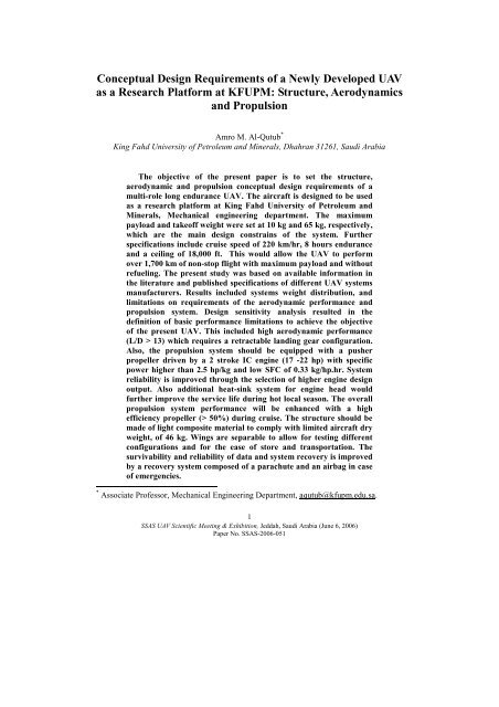
The objective <strong>of</strong> the present paper is to set the structure,<br />
aerodynamic and propulsion conceptual design requirements <strong>of</strong> a<br />
multi-role long endurance <strong>UAV</strong>. The aircraft is designed to be used<br />
<strong>as</strong> a research platform at King Fahd University <strong>of</strong> Petroleum and<br />
Minerals, Mechanical engineering department. The maximum<br />
payload and take<strong>of</strong>f weight were set at 10 kg and 65 kg, respectively,<br />
which are the main design constrains <strong>of</strong> the system. Further<br />
specifications include cruise speed <strong>of</strong> 220 km/hr, 8 hours endurance<br />
and a ceiling <strong>of</strong> 18,000 ft. This would allow the <strong>UAV</strong> to perform<br />
over 1,700 km <strong>of</strong> non-stop flight with maximum payload and without<br />
refueling. The present study w<strong>as</strong> b<strong>as</strong>ed on available information in<br />
the literature and published specifications <strong>of</strong> different <strong>UAV</strong> systems<br />
manufacturers. Results included systems weight distribution, and<br />
limitations on requirements <strong>of</strong> the aerodynamic performance and<br />
propulsion system. <strong>Design</strong> sensitivity analysis resulted in the<br />
definition <strong>of</strong> b<strong>as</strong>ic performance limitations to achieve the objective<br />
<strong>of</strong> the present <strong>UAV</strong>. This included high aerodynamic performance<br />
(L/D > 13) which requires a retractable landing gear configuration.<br />
Also, the propulsion system should be equipped with a pusher<br />
propeller driven by a 2 stroke IC engine (17 -22 hp) with specific<br />
power higher than 2.5 hp/kg and low SFC <strong>of</strong> 0.33 kg/hp.hr. System<br />
reliability is improved through the selection <strong>of</strong> higher engine design<br />
output. Also additional heat-sink system for engine head would<br />
further improve the service life during hot local se<strong>as</strong>on. The overall<br />
propulsion system performance will be enhanced with a high<br />
efficiency propeller (> 50%) during cruise. The structure should be<br />
made <strong>of</strong> light composite material to comply with limited aircraft dry<br />
weight, <strong>of</strong> 46 kg. Wings are separable to allow for testing different<br />
configurations and for the e<strong>as</strong>e <strong>of</strong> store and transportation. The<br />
survivability and reliability <strong>of</strong> data and system recovery is improved<br />
by a recovery system composed <strong>of</strong> a parachute and an airbag in c<strong>as</strong>e<br />
<strong>of</strong> emergencies.<br />
* Associate Pr<strong>of</strong>essor, Mechanical Engineering Department, aqutub@kfupm.edu.sa.<br />
1<br />
SSAS <strong>UAV</strong> Scientific Meeting & Exhibition, Jeddah, Saudi Arabia (June 6, 2006)<br />
Paper No. SSAS-2006-051
T<br />
I. Introduction<br />
HE Unmanned Aerial Vehicle (<strong>UAV</strong>) is a remotely piloted or self-piloted aircraft that<br />
can carry camer<strong>as</strong>, sensors, communications equipment or other payloads. <strong>UAV</strong><br />
technology and usage actually extends beyond Military and defense market. Many<br />
Universities around the world have their own <strong>UAV</strong> development program such <strong>as</strong><br />
University <strong>of</strong> Sydney, Clark University, Cranfield University, Georgia Tech. University 1 ,<br />
Berkeley University, Simon Fr<strong>as</strong>er University 2 , and others.<br />
For Example University <strong>of</strong> Sydney <strong>UAV</strong> fleet 3 is composed <strong>of</strong> five different flying<br />
<strong>UAV</strong>’s: KCEXP-series, Ariel (Figure 1), Brumby, T-Wing, and Bidule miniature Air<br />
vehicle. This besides all other <strong>UAV</strong> still under development such <strong>as</strong> The Solar powered<br />
High Altitude Endurance (HALE) meteorological <strong>UAV</strong>. The University <strong>of</strong> Sydney enjoys<br />
the funding from different organizations like Booing, and BAE.<br />
Figure1: Sydney University <strong>UAV</strong> examples: the Ariel (left) and the Brumby (right).<br />
King Fahd University <strong>of</strong> Petroleum and Minerals (KFUPM) is encouraging<br />
multidisciplinary projects where different department contribute and integrate a system in<br />
a specific technology field. KFUPM encouraged faculty to work towards a vision that may<br />
contribute to the well fear <strong>of</strong> the surrounding society and the enhancement <strong>of</strong> the<br />
dissemination <strong>of</strong> knowledge. The development <strong>of</strong> <strong>UAV</strong> in KFUPM h<strong>as</strong> the following<br />
mission:<br />
1. Develop know-how <strong>of</strong> <strong>UAV</strong> for local applications<br />
2. Provide experimental platform for multi-disciplinary research related to <strong>UAV</strong><br />
applications<br />
3. Provide a tool for academic excellence in different are<strong>as</strong>.<br />
The specific <strong>UAV</strong> should satisfy the following:<br />
• able to accommodate for equipments related to multi-disciplinary research and<br />
development work.<br />
• safe to operate<br />
• reliable for local environment<br />
• comply with local regulation <strong>of</strong> communication<br />
Building a <strong>UAV</strong> demands a v<strong>as</strong>t knowledge <strong>of</strong> b<strong>as</strong>e vehicle platforms, flight dynamics,<br />
control theory, and real-time s<strong>of</strong>tware in a network environment. The flight system enables<br />
the aircraft platform to serve <strong>as</strong> the autonomous agent. It requires sophisticated navigation<br />
2<br />
SSAS <strong>UAV</strong> Scientific Meeting & Exhibition, Jeddah, Saudi Arabia (June 6, 2006)<br />
Paper No. SSAS-2006-051
sensors and integration methodologies for accurate and reliable autonomous operation.<br />
Key <strong>UAV</strong> system technologies were identified to be in: airframes; propulsion units;<br />
autonomous flight controllers; launch and recovery; navigation and guidance; selfprotection;<br />
ground control stations; payloads; and data communication, storage,<br />
processing, and dissemination (Information Technology). Key system technologies cover<br />
the following items:<br />
• <strong>UAV</strong> airframe, structure and aerodynamics<br />
• Propulsion unit<br />
• Control system (Flight control, Propulsion control)<br />
• Telemetry and ground station<br />
• Instrumentation for performance evaluation and control<br />
• Support system<br />
The objective <strong>of</strong> the present paper is to study the specific conceptual design and<br />
performance requirements <strong>of</strong> the <strong>UAV</strong> structure, aerodynamics and propulsion system.<br />
II. General <strong>Requirements</strong><br />
1) Structure and Aerodynamics general requirements:<br />
• Composite structure + Aluminum alloy<br />
• Payload <strong>of</strong> 10 kg with gross take<strong>of</strong>f weight <strong>of</strong> 65 kg<br />
• Reinforced<br />
• Landing gears retractable<br />
• Support up to 5g’s<br />
• Internal fuel tank and equipments<br />
• Conventional high wing configuration for stability<br />
2) Flight general requirements:<br />
• Take <strong>of</strong>f and landing on paved ground<br />
• 160-220 Km/h cruise speed<br />
• 8+ hours endurance<br />
• Ceiling 6 km (18000 ft).<br />
3) Propulsion general requirements:<br />
• Internal combustion engine (IC) high performance<br />
• Propeller driven with minimum diameter and high efficiency during cruise<br />
• If possible electrical starter + alternator<br />
• Withstand up to 45 o C, and 55 o C for short duration during take<strong>of</strong>f<br />
• High engine efficiency with low SFC<br />
• High power/weight ratio<br />
In the design ph<strong>as</strong>e both engine efficiency and power/weight ratio have to be optimized for<br />
minimum system weight.<br />
B<strong>as</strong>ically the payload is the most important part in the design ph<strong>as</strong>e since it sets the<br />
limitations on possible missions the <strong>UAV</strong> can perform. For b<strong>as</strong>ic research and surveillance<br />
purposes 10 kg payload is considered sufficient since continuous developments in<br />
3<br />
SSAS <strong>UAV</strong> Scientific Meeting & Exhibition, Jeddah, Saudi Arabia (June 6, 2006)<br />
Paper No. SSAS-2006-051
electronics avails higher performance and lower weights sensors, camer<strong>as</strong> and processors.<br />
As shown in Figure 2, compared to conventional <strong>UAV</strong>'s, the payload-to-gross weight ratio<br />
% Payload/gross Weight<br />
70<br />
60<br />
50<br />
40<br />
30<br />
20<br />
10<br />
PAYLOAD vs Endurance<br />
0<br />
3 4 5 6 7 8 9 10<br />
Endurance (h)<br />
Figure 2: Payload vs Endurance <strong>of</strong> available Known Conventional<br />
<strong>UAV</strong>’s ( 4)<br />
Ceiling (feet)<br />
80,000<br />
70,000<br />
60,000<br />
50,000<br />
40,000<br />
30,000<br />
20,000<br />
10,000<br />
Present <strong>UAV</strong><br />
Service ceiling <strong>of</strong> <strong>UAV</strong>'s<br />
0<br />
0 10 20 30 40 50 60<br />
Endurance (h)<br />
Present <strong>UAV</strong><br />
Figure 3: Ceiling vs. Endurance <strong>of</strong> available Known Conventional<br />
<strong>UAV</strong>’s 4<br />
is average, however the endurance places the present <strong>UAV</strong> among the top <strong>of</strong> the group 4 .<br />
The ceiling is among the majority <strong>of</strong> <strong>UAV</strong>’s <strong>of</strong> its endurance category, Figure 3.<br />
4<br />
SSAS <strong>UAV</strong> Scientific Meeting & Exhibition, Jeddah, Saudi Arabia (June 6, 2006)<br />
Paper No. SSAS-2006-051
A. Aerodynamics and Structure<br />
B<strong>as</strong>ed on the objective <strong>of</strong> the project the <strong>UAV</strong> is a long endurance (8 hrs +) with<br />
re<strong>as</strong>onable cruise speed <strong>of</strong> about (220 km/hr). Moreover, take<strong>of</strong>f should be possible either<br />
from a launcher or a runway. This imposes a grate challenge in designing the<br />
aerodynamics and the structure <strong>of</strong> the aircraft. Endurance requires:<br />
− high aerodynamic performance (high L/D, lift to drag ratio)<br />
− Relatively Large fuel tank ( to improve weight ratio )<br />
− Strong structure with high strength to weight ratio materials.<br />
− Low thrust specific fuel (high efficiency propulsion system)<br />
Endurance<br />
To estimate the endurance <strong>of</strong> an aircraft we may start with the m<strong>as</strong>s reduction <strong>of</strong> fuel<br />
during level steady flight:<br />
dm ⎛ D ⎞<br />
= −TSFC<br />
∗ ⎜ ⎟(<br />
m • g)<br />
(1)<br />
dt<br />
⎝ L ⎠<br />
Where TSFC is the thrust specific fuel consumption <strong>of</strong> the propulsion system, m is the<br />
m<strong>as</strong>s <strong>of</strong> the vehicle, and g is the gravitational acceleration. Assuming constant L/D and<br />
TSFC through the flight, the endurance <strong>of</strong> the vehicle can be calculated <strong>as</strong>:<br />
1 ⎛ L ⎞ 1 mo<br />
Δ t = ⎜ ⎟ ln<br />
(2)<br />
g ⎝ D ⎠ TSFC mb<br />
Where mo is the take<strong>of</strong>f weight and mb is the fuel empty weight <strong>of</strong> the <strong>UAV</strong>.<br />
Take<strong>of</strong>f requirements<br />
The <strong>UAV</strong> h<strong>as</strong> to be able to take<strong>of</strong>f from a runway, or from a launcher. Taking <strong>of</strong>f from<br />
a runway requires landing gear system that reduces L/D if extended during flight. So,<br />
retractable landing gear should be used to maintain high aerodynamic performance. The<br />
major penalty in this c<strong>as</strong>e is incre<strong>as</strong>ed structural weight (by only few percent). A<br />
re<strong>as</strong>onable take<strong>of</strong>f velocity <strong>of</strong> the <strong>UAV</strong> is about 25 m/s. B<strong>as</strong>ed on the objective <strong>of</strong> the<br />
project, the maximum payload is 10kg. Referring to figure 3, the aircraft take<strong>of</strong>f gross<br />
weight can be chosen <strong>as</strong> 65 kg, which corresponds to payload to gross weight ratio <strong>of</strong><br />
15.4%. To calculate the wing platform area, we may use the lift equation:<br />
ρ 2 = V C S<br />
(3)<br />
2<br />
L L<br />
With plain flap system and large <strong>as</strong>pect ratio (>9) <strong>of</strong> the wing, maximum lift<br />
coefficient can reach a value over 1.4. Using equation (3), and considering the take<strong>of</strong>f<br />
speed to be grater than stall speed by 20%, the required wing area for the <strong>UAV</strong> for take<strong>of</strong>f<br />
5<br />
SSAS <strong>UAV</strong> Scientific Meeting & Exhibition, Jeddah, Saudi Arabia (June 6, 2006)<br />
Paper No. SSAS-2006-051
will be 1.66 m 2 at standard atmosphere. Higher atmospheric temperature and/or altitude<br />
would require slightly higher take<strong>of</strong>f speed due to reduced density. For example at 50 C o ,<br />
sea level, the take<strong>of</strong>f speed will be 26.5 m/s, only a 6% incre<strong>as</strong>e compared to standard<br />
atmosphere conditions.<br />
Structure<br />
The Present <strong>UAV</strong> h<strong>as</strong> a conventional aerodynamic configuration with pusher-type<br />
propeller See figure 4. The main fuselage h<strong>as</strong> a maximum diameter <strong>of</strong> about 350 mm to<br />
contain camer<strong>as</strong> similar to the BAI 5 <strong>as</strong> well <strong>as</strong> large fuel tank and Payload:<br />
Propeller<br />
Fuselage<br />
Camer<br />
a<br />
Figure 4: B<strong>as</strong>ic configuration <strong>of</strong> the <strong>UAV</strong>.<br />
The <strong>UAV</strong> is to be made from composites (gl<strong>as</strong>s fiber and/or Carbon fiber) and<br />
Aluminum alloy, to provide high strength to weight ratio. Skin parts and some <strong>of</strong> the<br />
skeleton supposed to be made from composite material while hard points and joints to be<br />
mainly from aluminum alloy for improved reliability. Part <strong>of</strong> the wing is supposed to be<br />
separable during storage and transportation for convenience <strong>of</strong> use and handling. For the<br />
systems contained in the fuselage they have to abide by the dimensional restrictions and<br />
maintain a re<strong>as</strong>onable static margin for stability purposes. Systems layout in the fuselage is<br />
illustrated in figure 5. Engine, landing gear and camera are supposed to have fixed<br />
locations. Fuel will be stored in multiple tanks, close to center <strong>of</strong> gravity for stability<br />
during flight and flexibility <strong>of</strong> payload <strong>as</strong> well <strong>as</strong> static margin consideration. The payload<br />
bay should contain flexible mount system for different parts and configuration <strong>of</strong><br />
communication, control and payloads. The camera is (which is a part <strong>of</strong> the payload)<br />
mounted at the bottom <strong>of</strong> the aircraft <strong>as</strong> shown in figure 5. Recovery Parachute and airbag<br />
h<strong>as</strong> to be on the center <strong>of</strong> gravity.<br />
6<br />
SSAS <strong>UAV</strong> Scientific Meeting & Exhibition, Jeddah, Saudi Arabia (June 6, 2006)<br />
Paper No. SSAS-2006-051
Fuel<br />
Tanks<br />
Propulsio<br />
n<br />
Cruise performance<br />
Figure 5 : Layout for Main systems in the Fuselage<br />
The <strong>UAV</strong> is expected to operate at a ceiling altitude <strong>of</strong> 18,000 ft. At the cruise speed <strong>of</strong><br />
220 km/hr the lift coefficient is CL = 0.31 (at gross weight). This is a re<strong>as</strong>onable lift<br />
coefficient for high aerodynamic performance. Lower speed will produce higher endurance<br />
and this can be optimized according to the type <strong>of</strong> the <strong>UAV</strong> mission. Moreover, the cruise<br />
speed <strong>of</strong> the present <strong>UAV</strong> is considered among the highest in its category <strong>as</strong> can be seen in<br />
table 1 6,7 .<br />
Table 1: Different <strong>UAV</strong> performance and power requirements 6,7 .<br />
<strong>UAV</strong> Gross<br />
Weight<br />
(kg)<br />
Parachute Payload bay<br />
Ceiling<br />
(ft)<br />
Airbag<br />
Endurance<br />
(hrs)<br />
Camera<br />
Main Landing Gear Nose Gear<br />
Cruise<br />
speed<br />
(km/hr)<br />
Power<br />
(hp)<br />
From Table 2 the weight to power ratio <strong>of</strong> <strong>UAV</strong>'s <strong>of</strong> similar category <strong>as</strong> the proposed is<br />
in the range <strong>of</strong> 2.4 to 5.2 kg/hp. The variation <strong>of</strong> designed hp on propulsion system<br />
depends on mainly on:<br />
7<br />
SSAS <strong>UAV</strong> Scientific Meeting & Exhibition, Jeddah, Saudi Arabia (June 6, 2006)<br />
Paper No. SSAS-2006-051<br />
W/P ratio<br />
(kg/hp)<br />
Huntair 127 17,000 7.5 184 38 3.3<br />
Raptor 854 65,000 8 - 50 17.1<br />
Prowler 91 21,000 6 100 38 2.4<br />
STM-5B 114 16,000 6 144 25.5 4.47<br />
Pectre II 100 23,000 6 220 26 3.85<br />
Skyeye 355 18,000 10 126 46 7.72<br />
Hunter 727 15,000 12 162 120 6.06<br />
Model 410 818 30,000 12 184 160 5.11<br />
Shadow 272 17,000 14 129 52 5.23
− Weight <strong>of</strong> the aircraft<br />
− Flight altitude<br />
− <strong>Design</strong> clime rate<br />
− Flight speed<br />
In the present work it is proposed to use an engine with 17 to 22 hp, which corresponds<br />
to a weight to power ratio <strong>of</strong> 3.82 to 3. This will put proposed <strong>UAV</strong> among the top <strong>of</strong> the<br />
<strong>UAV</strong>'s list in terms <strong>of</strong> engine power and performance. Actually the main re<strong>as</strong>ons <strong>of</strong> that<br />
are the high cruise speed and the high operating temperature in the local environment,<br />
which is part <strong>of</strong> the objective for this project. To calculate the endurance <strong>of</strong> the <strong>UAV</strong> the<br />
weight ratio h<strong>as</strong> to be known. Table 2 is a list <strong>of</strong> most recent <strong>UAV</strong> engines specification<br />
available in the world market that can be used for the present project 8-11 . B<strong>as</strong>ed on present<br />
technology, the propulsion system is expected to weigh about 9 kg, including engine,<br />
propeller and generator.<br />
Table.2: Some <strong>UAV</strong> Engines available in the international market.<br />
Engine<br />
Output<br />
Weight Power /Weight ratio<br />
(Brand)<br />
(hp)<br />
(kg)<br />
(hp/kg)<br />
A200B<br />
17 5.1 / 6 kg (est.)<br />
2.83<br />
Quadra<br />
300W Gen.<br />
3W-200i B2TSQS<br />
20 4.8/6 kg (est.)<br />
3.67<br />
3W Motoren<br />
W.Gen<br />
313<br />
22 8<br />
2.75<br />
Zanzotterra<br />
W. 300w Gen.<br />
L275 E<br />
25 7.7 / 9 kg (est.)<br />
2.78<br />
Limbach<br />
W. Gen<br />
AR741<br />
37<br />
10.7 /12kg (est.)<br />
3.1<br />
<strong>UAV</strong> Engine Ltd. (rotary)<br />
W. Gen.<br />
B<strong>as</strong>ed on the calculated size <strong>of</strong> wing and fuselage, the airframe <strong>of</strong> the <strong>UAV</strong> is expected<br />
to have a weight between 10 and 16 kg, depending on design and material used for the<br />
construction <strong>of</strong> the system. Table 3 provides the design weight <strong>of</strong> different systems in the<br />
<strong>UAV</strong>.<br />
Fuel consumption can be estimated using figure 6, which is an example for typical<br />
turboprop engine 12 . From this figure we can use a conservative thrust specific fuel<br />
consumption <strong>of</strong> 0.06 kg/N.hr. Using equation 2 with the <strong>as</strong>sumption <strong>of</strong> having an<br />
aerodynamic performance <strong>of</strong> L/D=15, the <strong>UAV</strong> endurance will be 11.14 hrs. This satisfies<br />
the objective <strong>of</strong> the project.<br />
Airframe Propulsion Control &<br />
communication<br />
Table 3: Weights <strong>of</strong> different system in the <strong>UAV</strong>.<br />
Landing<br />
Gear<br />
Recovery<br />
System<br />
Payload<br />
(Max.)<br />
Fuel<br />
with<br />
max<br />
payload<br />
8<br />
SSAS <strong>UAV</strong> Scientific Meeting & Exhibition, Jeddah, Saudi Arabia (June 6, 2006)<br />
Paper No. SSAS-2006-051<br />
Gross<br />
Weight<br />
12 kg 9 kg 3 kg 4 kg 4 kg 10 kg 23 kg 65 kg
Figure 6: Typical Engines TSFC (12)<br />
The calculated endurance is b<strong>as</strong>ed on several <strong>as</strong>sumptions regarding structural<br />
technology, aerodynamic technology and propulsion system performance. Figures 7 to 9<br />
Are the results <strong>of</strong> sensitivity analysis to illustrate the effect <strong>of</strong> each <strong>of</strong> the mentioned<br />
parameter on the endurance <strong>of</strong> the <strong>UAV</strong>. The total structure m<strong>as</strong>s includes airframe,<br />
propulsion, communication and control, landing gear, and recovery system. Reducing the<br />
structure weight to 26 kg will result an incre<strong>as</strong>ed endurance <strong>of</strong> over 15 hrs. If all typical<br />
values <strong>of</strong> aerodynamic performance and propulsion performance are met, the total<br />
structural m<strong>as</strong>s h<strong>as</strong> to be limited to 36 kg in order to meet the 8 hrs flight endurance Figure<br />
7. Aerodynamic performance also proved to be critical for endurance. Incre<strong>as</strong>ing<br />
aerodynamic performance will incre<strong>as</strong>e the endurance. The limit to meet the objective here<br />
is L/D ≥13, if all other variables are typical. Reducing the (TSFC) improves the flight<br />
endurance linearly, Figure 9. Improving the TSFC down to 0.045 will incre<strong>as</strong>e the<br />
endurance to 14.85 hrs. B<strong>as</strong>ed on available technology, the TSFC h<strong>as</strong> to be maintained<br />
below 0.06 during cruise conditions. Figure 10 illustrates the effect <strong>of</strong> different payload<br />
m<strong>as</strong>s on flight endurance. Reducing payload to 5 kg (half <strong>of</strong> max.) will incre<strong>as</strong>e flight<br />
endurance to 12.3 hrs, a 1.2 hrs incre<strong>as</strong>e over full payload (10kg). Detailed discussion on<br />
the propulsion system is at the next section.<br />
In conclusion, there are three main parameters that affect the flight endurance:<br />
− Structure design and material<br />
− Aerodynamic design<br />
− Propulsion system performance<br />
Structure and aerodynamics are to be optimized in the design process. Propulsion<br />
performance is considered <strong>as</strong> a major design constrain.<br />
9<br />
SSAS <strong>UAV</strong> Scientific Meeting & Exhibition, Jeddah, Saudi Arabia (June 6, 2006)<br />
Paper No. SSAS-2006-051
In conclusion the following are the aerodynamic and structure specifications:<br />
Aerodynamic:<br />
− High aerodynamic performance L/D>13<br />
− Pay load = 10 kg max<br />
− Gross weight 65 kg<br />
− Conventional configuration<br />
− Take<strong>of</strong>f speed = 25 m/s (standard atmosphere)<br />
− Wing Area 1.6 m 2 approx.<br />
− Max cruise 220 km/hr<br />
− Endurance 8 - 12 hrs.<br />
− Max ceiling 18,000 ft<br />
− Flight range > 1,800 km<br />
Structure:<br />
− Made <strong>of</strong> composites (fibergl<strong>as</strong>s-carbon) with Aluminum Alloy.<br />
− Separable wings.<br />
− Retractable landing gear<br />
− Recovery system (parachute + airbag)<br />
− Total Structure weight < 36 kg<br />
− Multiple Fuel tanks<br />
− Payload rack for flexibility <strong>of</strong> mounting with min dim. <strong>of</strong> (200X200X400) mm.<br />
Flight Endurance ( hrs )<br />
16<br />
14<br />
12<br />
10<br />
8<br />
6<br />
4<br />
2<br />
0<br />
26 29 32 35 38 41<br />
Structure m<strong>as</strong>s ( kg )<br />
Figure 7: Effect <strong>of</strong> Structure M<strong>as</strong>s on Flight Endurance<br />
10<br />
SSAS <strong>UAV</strong> Scientific Meeting & Exhibition, Jeddah, Saudi Arabia (June 6, 2006)<br />
Paper No. SSAS-2006-051
Flight Endurance ( hrs )<br />
Flight Endurance ( hrs )<br />
18<br />
16<br />
14<br />
12<br />
10<br />
8<br />
6<br />
11 13 15 17 19 21<br />
Aerodynamic Performance (L/D)<br />
Figure 8: Effect <strong>of</strong> Aerodynamic Performance on Flight Endurance<br />
18<br />
16<br />
14<br />
12<br />
10<br />
8<br />
6<br />
0.045 0.05 0.055 0.06 0.065 0.07 0.075<br />
TSFC ( kg/ N.hr )<br />
Figure 9: Effect <strong>of</strong> thrust Specific Fuel Consumption on Flight Endurance<br />
11<br />
SSAS <strong>UAV</strong> Scientific Meeting & Exhibition, Jeddah, Saudi Arabia (June 6, 2006)<br />
Paper No. SSAS-2006-051
Flight Endurance ( hrs )<br />
15<br />
14.5<br />
14<br />
13.5<br />
13<br />
12.5<br />
12<br />
11.5<br />
11<br />
10.5<br />
10<br />
Propulsion system<br />
The objective <strong>of</strong> the project requires a reliable and efficient propulsion system<br />
specifically during cruise condition (180 - 220 km/hr) with a ceiling <strong>of</strong> 18,000 ft. In<br />
addition, the <strong>UAV</strong> h<strong>as</strong> to be practical and e<strong>as</strong>y to maintain.<br />
Type <strong>of</strong> System<br />
10 8 6 4 2 1<br />
Payload M<strong>as</strong>s ( kg )<br />
Figure 10: Effect <strong>of</strong> Payload M<strong>as</strong>s on Flight Endurance, Fixed Fuel m<strong>as</strong>s <strong>of</strong> 23 kg.<br />
For the <strong>UAV</strong> application similar to present <strong>UAV</strong> category, propulsion systems are<br />
usually limited to either turbojet or propeller driven by an IC engine. Propeller <strong>UAV</strong> are<br />
more popular due to lower cost and higher efficiency at relatively low speeds (Ma
Engine <strong>Requirements</strong><br />
The engine h<strong>as</strong> to be able to operate in the local environment. So the b<strong>as</strong>ic<br />
requirements are:<br />
Cruise<br />
- Power to meet take<strong>of</strong>f at 9,000 ft altitude (Abha-Saudi Arabia)<br />
- Low fuel consumption to meet endurance requirements<br />
- Tolerate high temperature and dusty environment<br />
- Tolerate long periods <strong>of</strong> flights >20 hrs.<br />
- Tolerate high g forces during catapult launch.<br />
At level flight with a speed <strong>of</strong> V, the required propulsion power can be calculated <strong>as</strong>:<br />
Power P<br />
⎛ D ⎞<br />
= m g ⎜ ⎟ V<br />
(4)<br />
⎝ L ⎠<br />
For cruise at 18,000 ft and 220 km/hr, with gross weight <strong>of</strong> 65 kg and minimum L/D<br />
<strong>of</strong> 11, the required propulsion power will be Powerp = 3.54 kW ( 4.74 hp ). Typically, IC<br />
engines lose about 7% <strong>of</strong> output power per 3000 ft altitude. Taking this into consideration<br />
and <strong>as</strong>suming that the engine will operate at 67% <strong>of</strong> rated power during cruise, also<br />
<strong>as</strong>suming propeller efficiency <strong>of</strong> 60%, the required engine shaft power at standard<br />
atmospheric conditions should be about 20 hp, to meet the cruise condition. The extra 33%<br />
<strong>of</strong> engine power is for maneuver and climb requirement.<br />
High altitude take<strong>of</strong>f<br />
For take<strong>of</strong>f at 9,000 ft the power available will be 79% <strong>of</strong> the rated engine power. To<br />
maintain a re<strong>as</strong>onable weight to power ratio <strong>of</strong> less than 5.2 kg/hp, the engine rated shaft<br />
power should be > 15.82 hp. This is even less than the engine power requirement for cruise<br />
condition.<br />
Propeller Efficiency<br />
B<strong>as</strong>ed on endurance calculations, the required TSFC < 0.06 kg/N.hr. Most <strong>UAV</strong> engine<br />
suppliers claim specific fuel consumption (SFC) for their product <strong>as</strong> less than 0.33<br />
kg/hp.hr. Diesel engines recently developed for aviation application can reach SFC <strong>as</strong> low<br />
<strong>as</strong> 0.19 13 . The TSFC is affected by both SFC and propeller efficiency (ηp) :<br />
V<br />
TSFC = 0.<br />
00134 SFC<br />
(5)<br />
η<br />
13<br />
SSAS <strong>UAV</strong> Scientific Meeting & Exhibition, Jeddah, Saudi Arabia (June 6, 2006)<br />
Paper No. SSAS-2006-051<br />
P
Typical propeller efficiency can be <strong>as</strong> high <strong>as</strong> 85%, Figure 11. Usually each propeller<br />
design is b<strong>as</strong>ed on a given flight speed. <strong>Design</strong>ers should select propeller according to<br />
specific design requirement:<br />
- Power matching with engine<br />
- efficiency at cruise<br />
- static and low speed thrust<br />
- noise<br />
- diameter<br />
Propeller Efficiency (%)<br />
TSFC (kg/N.hr)<br />
80<br />
60<br />
40<br />
20<br />
100 200 300 400 500<br />
Flight Speed MPH<br />
Figure 11: Typical Propeller Efficiency (12)<br />
0.08<br />
0.07<br />
0.06<br />
0.05<br />
0.04<br />
0.03<br />
0.02<br />
0.01<br />
0<br />
0.4 0.5 0.6 0.7 0.8<br />
Propulsion Efficiency<br />
Figure 12: Effect <strong>of</strong> Propulsion Efficiency on Thrust Specific Fuel Consumption<br />
14<br />
SSAS <strong>UAV</strong> Scientific Meeting & Exhibition, Jeddah, Saudi Arabia (June 6, 2006)<br />
Paper No. SSAS-2006-051
For the present project the propeller selected should have maximum efficiency close to<br />
a speed <strong>of</strong> 200 km/hr. Figure 12 illustrates the required TSFC variation with propulsion<br />
efficiency for airspeed <strong>of</strong> 220 km/hr and SFC <strong>of</strong> 0.33 kg/hp.hr.<br />
From Figure 12 it is clear that to meet the endurance requirements the propulsion<br />
efficiency during cruise condition should be ηp > 45 %. The recommended efficiency <strong>of</strong><br />
propeller in the present study is 50% or better at cruise condition. This is consider a<br />
re<strong>as</strong>onable estimate compared to low speed propellers. 13,14 Altitude and flight speed will<br />
change the propeller size and configuration to meet the efficiency requirement. So, more<br />
than one propeller type should be used to meet different altitudes and flight speed for<br />
optimum performance. The propulsion requirements are <strong>as</strong> the following:<br />
a) Engine :<br />
− 20 -25 hp Two stroke engine with:<br />
− SFC < 0.33 kg/hp.hr (at cruise)<br />
− Power to weight ratio > 2.5 kg/hp (including generator)<br />
− Ability to operate to temperatures up to 45 o C<br />
− Ability to operate in dusty environment (equipped with intake filter)<br />
− Able to with stand axial acceleration > 10 g.<br />
− Operate efficiently at max altitude 18,000 ft<br />
− Self priming ignition system with min. 100 W generator.<br />
b) Propeller: :<br />
− Pusher type<br />
− Meets engine power<br />
− 70-80 cm diameter, minimum possible size<br />
− Efficiency ≥ 50% at cruise condition<br />
III. Conclusion<br />
The major objective <strong>of</strong> the multi-role <strong>UAV</strong> is to be capable <strong>of</strong> long endurance (8-12<br />
hrs) flights with a maximum payload <strong>of</strong> 10 kg. The maximum expected cruise speed is 220<br />
km/hr, and the ceiling is 18,000 ft. This would allow the <strong>UAV</strong> to perform over 1,700 km<br />
<strong>of</strong> non-stop flight with maximum payload and without refueling. Compliance to<br />
specifications limits <strong>of</strong> different systems is expected to <strong>as</strong>sure achievement to the<br />
objectives <strong>of</strong> this project. The present study w<strong>as</strong> b<strong>as</strong>ed on available information in the<br />
literature and published specifications <strong>of</strong> manufacturers. <strong>Design</strong> constrains are identified<br />
<strong>as</strong>:<br />
− Available engine performance and specifications<br />
− Available control system specifications (size – weight-power)<br />
− Communication System<br />
Other major specifications can be met through careful design and execution. B<strong>as</strong>ed on<br />
design sensitivity analysis the <strong>UAV</strong> is expected to have a conventional aerodynamic<br />
configuration with pusher propeller driven by a 2 stroke IC engine with > 20 hp output for<br />
improved reliability. Special heat sinks for engine heads are recommended for improved<br />
reliability <strong>of</strong> the system during hot local se<strong>as</strong>on. Also, the structure should be made <strong>of</strong> light<br />
15<br />
SSAS <strong>UAV</strong> Scientific Meeting & Exhibition, Jeddah, Saudi Arabia (June 6, 2006)<br />
Paper No. SSAS-2006-051
composite material to comply with limited aircraft dry weight <strong>of</strong> 36 kg. This would<br />
provide a tolerance <strong>of</strong> 4 kg for the structural components <strong>of</strong> the aircraft in the design and<br />
construction ph<strong>as</strong>e compared to the typical design in table 3. Wings should be separable<br />
for e<strong>as</strong>e <strong>of</strong> store and transportation. Moreover, aerodynamic performance (L/D) have to be<br />
grater than 13, which requires a retractable landing gear configuration. In addition, the<br />
engine h<strong>as</strong> to have high specific power > 2.5 hp/kg, with low SFC< 0.33 kg/hp.hr. Also,<br />
the propeller should have high efficiency during cruise (> 50%). Survivability <strong>of</strong> the <strong>UAV</strong><br />
is improved by a recovery system composed <strong>of</strong> a parachute and an airbag in c<strong>as</strong>e <strong>of</strong><br />
emergencies.<br />
Acknowledgment<br />
The author acknowledges the support <strong>of</strong> King Fahd University <strong>of</strong> Petroleum and<br />
Minerals during this research.<br />
References<br />
1 Johnson, E. N., Hart, M. G., and Christophersen, H.B., “Development <strong>of</strong> an Autonomous Aerial<br />
Reconnaissance System at Georgia Tech,” AIAA's 1 st Technical Conference and Workshop on<br />
Unmanned Aerospace Vehicles, Systems, Technologies, and Operations, 20-23 May 2002<br />
2 Hennessey, C., “Autonomous Control <strong>of</strong> a Scale Airplane,” School <strong>of</strong> Engineering Science, Simon<br />
Fr<strong>as</strong>er University, 14 April 2000<br />
3 Wang K.C." <strong>UAV</strong> <strong>Design</strong> Activities in a University Environment" presented at the 9th Australian<br />
International Aerospace Congress, Canberra, Australia, 6-8 March 2001 (PDF 4.0 file)<br />
4 Amro M. Al-Qutub and Sami El Ferik "System Definition for Unmanned Aircraft Development"<br />
KFUPM Internal Report Jun, 2003.<br />
5 BAI Aero systems. Payloads and Sensors. www.baiaerosystems.com/payloads.html<br />
6 <strong>UAV</strong> forum: http://www.uavforum.com/index.shtml<br />
7 Association for Unmanned Vehicle Systems International: http://www.auvsi.org/<br />
8 <strong>UAV</strong> Engines Ltd.: http://www.uavenginesltd.co.uk<br />
9 Zanzottera Engines: http://www.zazoterteraengines.com<br />
10 Limbach Engines: http://www.limflug.de<br />
11 3W Modellmotoren GmBH Engines: http://www.3w-modellmotoren.com<br />
12 Hill and Peterson "Mechanics and Thermodynamics <strong>of</strong> Propulsion", Addition-Wesley, 2 nd edition,<br />
1992<br />
13 Shaila L. J<strong>as</strong>zlics and Rianer Stemme " Possibility <strong>of</strong> the Next Generation <strong>of</strong> High-Altitude Long-<br />
Endurance Unmanned Aerial Vehicles" Technical Publication/ HALE-<strong>UAV</strong>.<br />
14 F 2 Craig D. Paxton, Peter J. Gryn, Eerisa Hines, Ulises Perez, and Ge-Cheng Zha " High<br />
Efficiency Foreword Swept Propellers at Low Speed" AIAA 2003-1069.<br />
16<br />
SSAS <strong>UAV</strong> Scientific Meeting & Exhibition, Jeddah, Saudi Arabia (June 6, 2006)<br />
Paper No. SSAS-2006-051