

Journal of Networks - Academy Publisher
Journal of Networks - Academy Publisher
Journal of Networks - Academy Publisher

Create successful ePaper yourself
Turn your PDF publications into a flip-book with our unique Google optimized e-Paper software.
154 JOURNAL OF NETWORKS, VOL. 5, NO. 2, FEBRUARY 2010<br />
channel interference. Hence, the impact <strong>of</strong> such a drift on<br />
the performance <strong>of</strong> a DWDM system is examined in the<br />
following section.<br />
C. Performance Degradation due to Switching Drift<br />
The set-up shown in Fig. 3 is employed to investigate<br />
the effect <strong>of</strong> the measured wavelength drift in a dense<br />
wavelength division multiplexed network. A twotransmitter<br />
DWDM system with channel spacing <strong>of</strong> 12.5<br />
GHz is investigated. The tunable is set to switch between<br />
channel 42 and 52. A fixed laser is used as a second<br />
transmitter operating 12.5 GHz away from the tunable<br />
laser target channel at 1544.824 nm. Each channel is<br />
externally modulated with a 2.5 Gbit/s Non-Return-to-<br />
Zero (NRZ) pseudo-random bit sequence with a pattern<br />
length <strong>of</strong> 2 7 -1.<br />
Figure 3. Set-up to investigate the effect <strong>of</strong> the measured wavelength<br />
drift in a DWDM network<br />
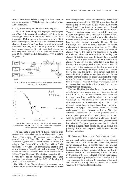
Figure 4. BER measurements for 12.5 GHz channel spacing with<br />
default blanking time (▲) and <strong>of</strong> 12.5 GHz channel spacing using and<br />
extended blanking time <strong>of</strong> 200 ns (○)<br />
The same data is used for both lasers, therefore it is<br />
necessary to de-correlate the information carried in each<br />
channel. This is achieved by passing one <strong>of</strong> the channels<br />
through 3 m <strong>of</strong> fiber. The two channels are then<br />
combined together and the fixed channel is filtered out<br />
using a Fabry-Perot (FP) tunable filter with a 3 dB<br />
bandwidth <strong>of</strong> 6 GHz. The demultiplexed channel then<br />
passes through a Variable Optical Attenuator (VOA)<br />
before entering the receiver stage which consists <strong>of</strong> an<br />
Erbium Doped Fibre Amplifier (EDFA), an optical filter,<br />
a photodiode and an electrical amplifier. The signal<br />
spectrum, eye diagram and the BER <strong>of</strong> the detected<br />
channel are also examined.<br />
The BER <strong>of</strong> the filtered channel is measured as a<br />
function <strong>of</strong> the received optical power for various tunable<br />
© 2010 ACADEMY PUBLISHER<br />
laser configurations – when the interfering tunable laser<br />
was (a) set to channel 42 (> 500 GHz away from filtered<br />
channel), (b) set to channel 52 (12.5 GHz from filtered<br />
channel) and (c) switching from channel 42 to channel<br />
52. The tunable laser is set to switch at a rate <strong>of</strong> 5 kHz.<br />
There is a minimal power penalty (


