

Journal of Networks - Academy Publisher
Journal of Networks - Academy Publisher
Journal of Networks - Academy Publisher

You also want an ePaper? Increase the reach of your titles
YUMPU automatically turns print PDFs into web optimized ePapers that Google loves.
160 JOURNAL OF NETWORKS, VOL. 5, NO. 2, FEBRUARY 2010<br />
ps/nm pre-compensation, or if the improvement <strong>of</strong> one<br />
method is very high.<br />
a) b)<br />
c)<br />
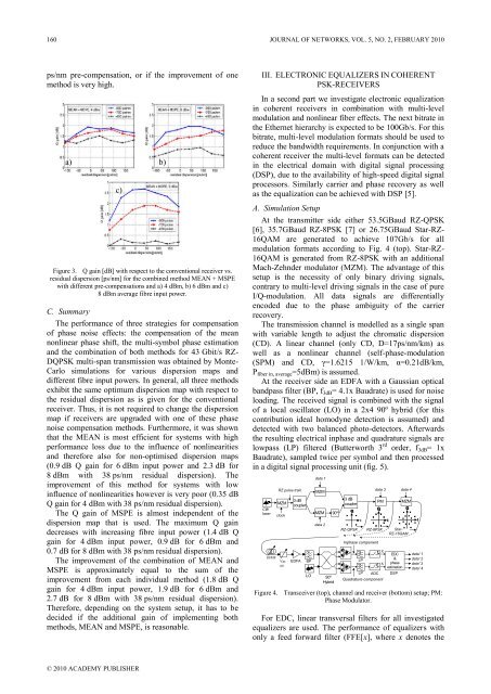
Figure 3. Q gain [dB] with respect to the conventional receiver vs.<br />
residual dispersion [ps/nm] for the combined method MEAN + MSPE<br />
with different pre-compensations and a) 4 dBm, b) 6 dBm and c)<br />
8 dBm average fibre input power.<br />
C. Summary<br />
The performance <strong>of</strong> three strategies for compensation<br />
<strong>of</strong> phase noise effects: the compensation <strong>of</strong> the mean<br />
nonlinear phase shift, the multi-symbol phase estimation<br />
and the combination <strong>of</strong> both methods for 43 Gbit/s RZ-<br />
DQPSK multi-span transmission was obtained by Monte-<br />
Carlo simulations for various dispersion maps and<br />
different fibre input powers. In general, all three methods<br />
exhibit the same optimum dispersion map with respect to<br />
the residual dispersion as is given for the conventional<br />
receiver. Thus, it is not required to change the dispersion<br />
map if receivers are upgraded with one <strong>of</strong> these phase<br />
noise compensation methods. Furthermore, it was shown<br />
that the MEAN is most efficient for systems with high<br />
performance loss due to the influence <strong>of</strong> nonlinearities<br />
and therefore also for non-optimised dispersion maps<br />
(0.9 dB Q gain for 6 dBm input power and 2.3 dB for<br />
8 dBm with 38 ps/nm residual dispersion). The<br />
improvement <strong>of</strong> this method for systems with low<br />
influence <strong>of</strong> nonlinearities however is very poor (0.35 dB<br />
Q gain for 4 dBm with 38 ps/nm residual dispersion).<br />
The Q gain <strong>of</strong> MSPE is almost independent <strong>of</strong> the<br />
dispersion map that is used. The maximum Q gain<br />
decreases with increasing fibre input power (1.4 dB Q<br />
gain for 4 dBm input power, 0.9 dB for 6 dBm and<br />
0.7 dB for 8 dBm with 38 ps/nm residual dispersion).<br />
The improvement <strong>of</strong> the combination <strong>of</strong> MEAN and<br />
MSPE is approximately equal to the sum <strong>of</strong> the<br />
improvement from each individual method (1.8 dB Q<br />
gain for 4 dBm input power, 1.9 dB for 6 dBm and<br />
2.7 dB for 8 dBm with 38 ps/nm residual dispersion).<br />
Therefore, depending on the system setup, it has to be<br />
decided if the additional gain <strong>of</strong> implementing both<br />
methods, MEAN and MSPE, is reasonable.<br />
© 2010 ACADEMY PUBLISHER<br />
III. ELECTRONIC EQUALIZERS IN COHERENT<br />
PSK-RECEIVERS<br />
In a second part we investigate electronic equalization<br />
in coherent receivers in combination with multi-level<br />
modulation and nonlinear fiber effects. The next bitrate in<br />
the Ethernet hierarchy is expected to be 100Gb/s. For this<br />
bitrate, multi-level modulation formats should be used to<br />
reduce the bandwidth requirements. In conjunction with a<br />
coherent receiver the multi-level formats can be detected<br />
in the electrical domain with digital signal processing<br />
(DSP), due to the availability <strong>of</strong> high-speed digital signal<br />
processors. Similarly carrier and phase recovery as well<br />
as the equalization can be achieved with DSP [5].<br />
A. Simulation Setup<br />
At the transmitter side either 53.5GBaud RZ-QPSK<br />
[6], 35.7GBaud RZ-8PSK [7] or 26.75GBaud Star-RZ-<br />
16QAM are generated to achieve 107Gb/s for all<br />
modulation formats according to Fig. 4 (top). Star-RZ-<br />
16QAM is generated from RZ-8PSK with an additional<br />
Mach-Zehnder modulator (MZM). The advantage <strong>of</strong> this<br />
setup is the necessity <strong>of</strong> only binary driving signals,<br />
contrary to multi-level driving signals in the case <strong>of</strong> pure<br />
I/Q-modulation. All data signals are differentially<br />
encoded due to the phase ambiguity <strong>of</strong> the carrier<br />
recovery.<br />
The transmission channel is modelled as a single span<br />
with variable length to adjust the chromatic dispersion<br />
(CD). A linear channel (only CD, D=17ps/nm/km) as<br />
well as a nonlinear channel (self-phase-modulation<br />
(SPM) and CD, γ=1.6215 1/W/km, α=0.21dB/km,<br />
Pfiber in, average=5dBm) is assumed.<br />
At the receiver side an EDFA with a Gaussian optical<br />
bandpass filter (BP, f3dB= 4.1x Baudrate) is used for noise<br />
loading. The received signal is combined with the signal<br />
<strong>of</strong> a local oscillator (LO) in a 2x4 90º hybrid (for this<br />
contribution ideal homodyne detection is assumed) and<br />
detected with two balanced photo-detectors. Afterwards<br />
the resulting electrical inphase and quadrature signals are<br />
lowpass (LP) filtered (Butterworth 3 rd order, f3dB= 1x<br />
Baudrate), sampled twice per symbol and then processed<br />
in a digital signal processing unit (fig. 5).<br />
CW<br />
laser<br />
SSMF<br />
RZ pulse train<br />
MZM<br />
clock<br />
Var.<br />
att.<br />
3 dB<br />
coupler<br />
EDFA<br />
BP<br />
LO<br />
data 1<br />
MZM<br />
MZM 90º<br />
data 2<br />
90º<br />
Hybrid<br />
3 dB<br />
coupler<br />
RZ-QPSK<br />
Inphase component<br />
LP<br />
LP<br />
data 3<br />
PM<br />
Quadrature component<br />
data 4<br />
MZM<br />
RZ-8PSK Star-<br />
RZ-16QAM<br />
ADC<br />
X r<br />
X i<br />
EDC<br />
&<br />
phase<br />
estimation<br />
DSP<br />
data' 1<br />
data' 2<br />
data' 3<br />
data' 4<br />
Figure 4. Transceiver (top), channel and receiver (bottom) setup; PM:<br />
Phase Modulator.<br />
For EDC, linear transversal filters for all investigated<br />
equalizers are used. The performance <strong>of</strong> equalizers with<br />
only a feed forward filter (FFE[x], where x denotes the


