Download PDF file
Download PDF file
Download PDF file
- TAGS
- download
- 81.169.135.155

You also want an ePaper? Increase the reach of your titles
YUMPU automatically turns print PDFs into web optimized ePapers that Google loves.
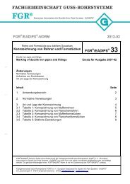
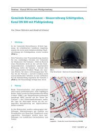
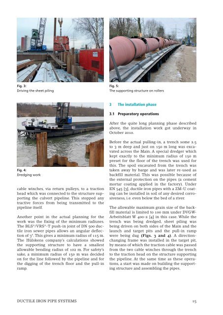
Fig. 3:<br />
Driving the sheet piling<br />
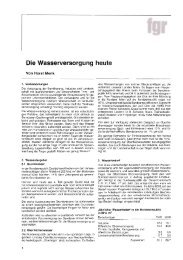
Fig. 4:<br />
Dredging work<br />
cable winches, via return pulleys, to a traction<br />
head which was connected to the structure supporting<br />
the culvert pipeline. This stopped any<br />
tractive forces from being transmitted to the<br />
pipeline itself.<br />
Another point in the actual planning for the<br />
work was the fixing of the minimum radiuses.<br />
The BLS®/VRS®-T push-in joint of DN 500 ductile<br />
iron sewer pipes allows an angular deflection<br />
of 3°. This gives a minimum radius of 115 m.<br />
The Hülskens company’s calculations showed<br />
the supporting structure to have a smallest<br />
allowable bending radius of 102 m. For safety’s<br />
sake, a minimum radius of 150 m was decided<br />
on for the line followed by the pipeline and for<br />
the digging of the trench floor and the pull-in<br />
ramp.<br />
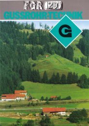
Fig. 5:<br />
The supporting structure on rollers<br />
3 The installation phase<br />
3.1 Preparatory operations<br />
After the quite long planning phase described<br />
above, the installation work got underway in<br />
October 2010.<br />
Before the actual pulling-in, a trench some 2.5<br />
to 3 m deep and just on 150 m long was excavated<br />
across the Main. A special dredger which<br />
kept exactly to the minimum radius of 150 m<br />
preset for the floor of the trench was used for<br />
this. The spoil excavated from the trench was<br />
taken away by barge and was later re-used as<br />
backfill material. This was possible because of<br />
the external protection on the pipes (a cement<br />
mortar coating applied in the factory). Under<br />
EN 545 [3], ductile iron pipes with a ZM-U coating<br />
can be installed in soil of any desired corrosiveness,<br />
i.e. even below the bed of a river.<br />
The allowable maximum grain size of the backfill<br />
material is limited to 100 mm under DVGW-<br />
Arbeitsblatt W 400-2 [4] in this case. While the<br />
trench was being dredged, sheet piling was<br />
being driven on both sides of the Main and the<br />
launch and target pits and the pull-in ramp<br />
were being dug (Figs. 3 and 4). A directionchanging<br />
frame was installed in the target pit,<br />
by means of which the traction cable was passed<br />
from the two cable winches through the trench<br />
to the traction head on the structure supporting<br />
the pipeline. At the same time as these operations,<br />
a start was made on building the supporting<br />
structure and assembling the pipes.<br />
DUCTILE IRON PIPE SYSTEMS 15