Download PDF file
Download PDF file
Download PDF file
- TAGS
- download
- 81.169.135.155

Create successful ePaper yourself
Turn your PDF publications into a flip-book with our unique Google optimized e-Paper software.
4.2 Inspection of the old pipeline<br />
and determination of its state<br />
As in any trenchless replacement operation,<br />
the pipeline to be replaced was subjected to a<br />
thorough examination.<br />
Even while the pits were being dug, the sections<br />
of pipeline which were cut out in the course of<br />
this were examined for their degree of fouling,<br />
the properties of their material and their residual<br />
load-bearing capacity. This latter one was<br />
particularly significant for the subsequent procedure.<br />
Whether the pipeline needed further<br />
strengthening before the replacement depended<br />
on it. The pipeline which had been cut open was<br />
also subjected to a visual inspection, the path<br />
followed by it was documented and the positions<br />
of valves and other installed items were<br />
established from drawings. All these had to be<br />
removed as otherwise there would have been an<br />
uncontrolled rise in the tractive force.<br />
4.3 Preparation of the old pipeline<br />
It was found that the load-bearing capacity<br />
was not in fact high enough for the intended<br />
replacement technique. It was very likely that<br />
the walls of the pipes would collapse as the<br />
pipeline was being pressed out and would<br />
therefore make continued pressing impossible.<br />
The installing company therefore decided to<br />
undertake retrospective strengthening.<br />
For this purpose, a DN 150 PVC pipe for connecting<br />
to sewers was slid concentrically into<br />
the old pipe on spacers. The annular gap around<br />
7 cm wide which was created in this way was<br />
then grouted with a special mortar. This mortar<br />
was notable for its good flowability, and its<br />
high capacity for swelling and resistance to<br />
compression. The curing time of the mortar was<br />
five days. The nominal size of the PVC pipe was<br />
firstly intended to produce as large an annular<br />
gap as possible and hence as large as possible<br />
a cross-section for the concrete. Secondly the<br />
140 mm diameter traction string had to fit into<br />
it.<br />
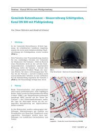
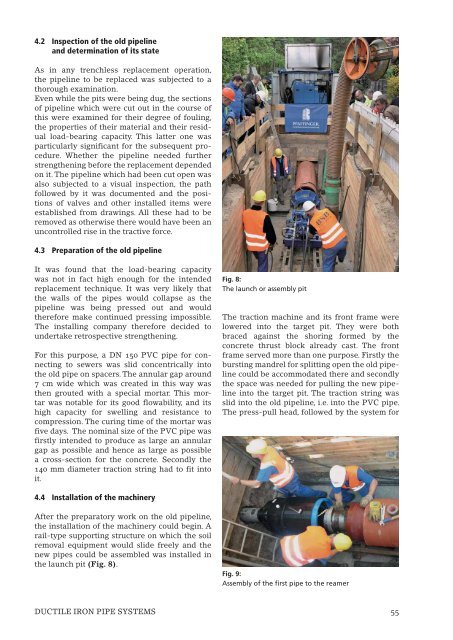
4.4 Installation of the machinery<br />
After the preparatory work on the old pipeline,<br />
the installation of the machinery could begin. A<br />
rail-type supporting structure on which the soil<br />
removal equipment would slide freely and the<br />
new pipes could be assembled was installed in<br />
the launch pit (Fig. 8).<br />
Fig. 8:<br />
The launch or assembly pit<br />
The traction machine and its front frame were<br />
lowered into the target pit. They were both<br />
braced against the shoring formed by the<br />
concrete thrust block already cast. The front<br />
frame served more than one purpose. Firstly the<br />
bursting mandrel for splitting open the old pipeline<br />
could be accommodated there and secondly<br />
the space was needed for pulling the new pipeline<br />
into the target pit. The traction string was<br />
slid into the old pipeline, i.e. into the PVC pipe.<br />
The press-pull head, followed by the system for<br />
Fig. 9:<br />
Assembly of the first pipe to the reamer<br />
DUCTILE IRON PIPE SYSTEMS 55