An Asynchronous Microprocessor in Gallium Arsenide Jose A ...
An Asynchronous Microprocessor in Gallium Arsenide Jose A ...
An Asynchronous Microprocessor in Gallium Arsenide Jose A ...

You also want an ePaper? Increase the reach of your titles
YUMPU automatically turns print PDFs into web optimized ePapers that Google loves.
a<br />
b<br />
c<br />
d<br />
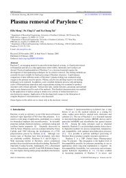
(a) (b)<br />
Figure 4: Multi-<strong>in</strong>put C-element.<br />
diagram<br />
(a) Transistor schematic, and (b) logical<br />
buffer stage allows the output low voltage to be low enough, s<strong>in</strong>ce the pull-down<br />
does not have to fight a passive pull-up. The lower output low <strong>in</strong>creases the<br />
noise marg<strong>in</strong>s considerably, with a small penalty <strong>in</strong> area and power.<br />
Super-buffers were used to buffer bus and control signals. To improve performance<br />
and noise marg<strong>in</strong> characteristics, a feed-back transistor was added,<br />
creat<strong>in</strong>g a "squeeze" buffer (see Figure l(c) [Br092]). Squeeze buffers allow the<br />
use of a stronger pull-up transistor, the feed-back transistor limits the output<br />
high voltage.<br />
To generate completion signals from the datapath, we use C-elements with a<br />
large number of <strong>in</strong>puts. They can be built from smaller C-elements connected <strong>in</strong><br />
a tree [Mar90], or, as <strong>in</strong> this case, as a s<strong>in</strong>gle logic gate (see Figure 4( a) and (b)).<br />
For a discussion on how this circuit works, see [Tie92J. Though a completion<br />
tree could be implemented with DCFL nor gates, it would be significantly slower<br />
and bigger than that of Figure 4(a). Completion detection is <strong>in</strong> sequence with<br />
the calculations performed by the datapath, and affects performance directly.<br />
It is critical to have an easy and fast way of generat<strong>in</strong>g the completion signal.<br />
4.2 Control Logic<br />
Control logic takes care of the sequenc<strong>in</strong>g of actions <strong>in</strong> the processor. After<br />
compilation, each control signal is assigned a set of "production rules", of the<br />
form:<br />
G -+ zi<br />
H -+ zl<br />
where G and H are boolean expressions <strong>in</strong> terms of the other signals. G and<br />
H do not have to be complementary. In fact, most operators <strong>in</strong> the control are<br />
7