An Asynchronous Microprocessor in Gallium Arsenide Jose A ...
An Asynchronous Microprocessor in Gallium Arsenide Jose A ...
An Asynchronous Microprocessor in Gallium Arsenide Jose A ...

Create successful ePaper yourself
Turn your PDF publications into a flip-book with our unique Google optimized e-Paper software.
<strong>An</strong> <strong>Asynchronous</strong> <strong>Microprocessor</strong> <strong>in</strong> <strong>Gallium</strong><br />
<strong>Arsenide</strong><br />
<strong>Jose</strong> A. Tierno<br />
Ala<strong>in</strong> J. Mart<strong>in</strong><br />
Dralen Borkovic<br />
Tak Kwan Lee<br />
Computer Science Department<br />
California Institute of Technology<br />
Caltech-CS-TR-93-38
<strong>An</strong> <strong>Asynchronous</strong> <strong>Microprocessor</strong> <strong>in</strong> <strong>Gallium</strong><br />
<strong>Arsenide</strong><br />
<strong>Jose</strong> A. Tierno Ala<strong>in</strong> J. Mart<strong>in</strong> Drazen Borkovic<br />
Tak Kwan Lee<br />
Department of Computer Science<br />
California Institute of Technology<br />
Pasadena, CA 91125<br />
November 9, 1993<br />
Abstract<br />
In this paper, several techniques for design<strong>in</strong>g asynchronous circuits<br />
<strong>in</strong> <strong>Gallium</strong> <strong>Arsenide</strong> are presented. Several new circuits were designed, to<br />
implement specific functions necessary to the design of a full microprocessor.<br />
A sense-amplifier, a completion tree, and a general circuit structure<br />
for operators specified by production rules are <strong>in</strong>troduced. These circuit<br />
were used and tested <strong>in</strong> a variety of designs, <strong>in</strong>clud<strong>in</strong>g two asynchronous<br />
microprocessors and two asynchronous static RAM's. One of the microprocessor<br />
runs at over 100 MIPS with a power consumption of 2 Watts.<br />
1 Introduction<br />
With an electron mobility about six times that of silicon at room temperature,<br />
and with a lower parasitic capacitance due to semi-<strong>in</strong>sulat<strong>in</strong>g substrate, GaAs is<br />
potentially faster than silicon. Up until recently, however, GaAs was not available<br />
to the VLSI community at large because of <strong>in</strong>herent fabrication difficulties.<br />
These difficulties have been overcome to a large extent. Several foundries are<br />
now offer<strong>in</strong>g GaAs fabrication l<strong>in</strong>es under conditions similar to CMOS, with<br />
density limited to about 100,000 transistors. In particular, Vitesse Semiconductors<br />
is offer<strong>in</strong>g fabrication through MOSIS to the academic community <strong>in</strong> the<br />
United States.<br />
At the moment, the transistor of choice for GaAs digital VLSI is the MES<br />
FET. There is no oxide <strong>in</strong>sulat<strong>in</strong>g the gate of a MESFET transistor from source<br />
and dra<strong>in</strong>; therefore, the logic families available <strong>in</strong> GaAs are much less attractive<br />
than CMOS or even nMOS. DCFL has been adapted to GaAs, but has very reduced<br />
noise marg<strong>in</strong>s, and restricted fan<strong>in</strong> and fanout. With no complementary<br />
1
transistor available, the logic is ratioed. As a result, a considerable fraction of<br />
the speed advantage is lost due to the complexity of the available logic families<br />
relative to CMOS.<br />
We have developed a design method for asynchronous VLSI that is, to a<br />
large extent, technology <strong>in</strong>dependent. Thus, it should be straightforward to<br />
port a design from one technology to another. Also, s<strong>in</strong>ce the circuits designed<br />
are delay-<strong>in</strong>sensitive, they are more robust with respect to variations <strong>in</strong> physical<br />
parameters. Hence, the method should make it easier to design <strong>in</strong> a demand<strong>in</strong>g<br />
technology such as GaAs, where parameters-particularly threshold voltagesare<br />
difficult to control. F<strong>in</strong>ally, s<strong>in</strong>ce the circuits we design do not use a clock,<br />
we avoid the complexities of high-speed clock<strong>in</strong>g schemes. Adapt<strong>in</strong>g our method<br />
to GaAs design would be an excellent demonstration of the advantages of the<br />
method.<br />
From the onset, our <strong>in</strong>tention was to port to GaAs the asynchronous microprocessor<br />
we designed <strong>in</strong> CMOS <strong>in</strong> 1989 [MBL +89]. At the same time, we would<br />
demonstrate the portability of our approach across vastly different technologies,<br />
and the efficiency and robustness of the design method.<br />
To this end, several special purpose circuits had to be designed. Some of<br />
them are presented <strong>in</strong> this paper, together with their use <strong>in</strong> the microprocessor.<br />
2 GaAs and the MESFET<br />
2.1 MEtal Semiconductor Field Effect Transistor<br />
The MEtal Semiconductor Field Effect Transistor, or MESFET, is the transistor<br />
of choice for GaAs VLSI applications. It is the easiest to manufacture, provides<br />
the highest density (about 100,000 transistors on a chip), and has a very good<br />
power-delay product, that competes fairly well with CMOS. MESFET circuits<br />
can be better compared to ECL. At this po<strong>in</strong>t, GaAs is slightly faster, uses<br />
far less power, and has higher circuit density, for a similar cost. <strong>An</strong> important<br />
application of GaAs is to provide replacements for ECL parts, specially fast<br />
RAM's, and other LSI circuits.<br />
MESFET's are junction FET's. The gate is built with metal, and forms a<br />
Schottky junction with the transistor channel. There is no <strong>in</strong>sulation between<br />
gate and channel; the Schottky junction creates a diode from gate to source<br />
and from gate to dra<strong>in</strong>. This diode is probably the most serious constra<strong>in</strong>t for<br />
MESFET circuits, s<strong>in</strong>ce it limits the voltage differential between gate and source<br />
or dra<strong>in</strong> to the diode's forward conduction voltage, about 0.7 volts. Above that<br />
difference, the diode will be forward biased and current will flow from the gate<br />
<strong>in</strong>to the channel.<br />
Hole mobility is low <strong>in</strong> GaAs (10 times less than electron mobility [LB90]),<br />
which makes p-type FETs fairly slow. There is, therefore, no complementary<br />
logic available. As <strong>in</strong> nMOS, n-type transistors come <strong>in</strong> two flavors, depletion-<br />
2
a<br />
a b b l n ---jr=":"'::""---1<br />
(a) (b) c<br />
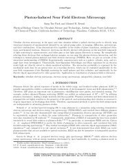
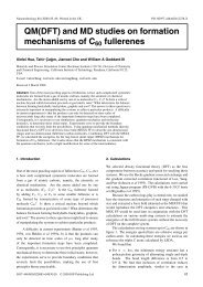
Figure 1: (a) DCFL nor gate, (b) super buffered nand gate, and (c) "squeeze"<br />
buffer<br />
mode and enhancement-mode. E-mode transistors have a positive threshold<br />
voltage, and d-mode have a negative threshold voltage, that is, they require a<br />
negative gate to source voltage to be cut off.<br />
2.2 Direct Coupled Fet Logic<br />
<strong>An</strong>alogous to its nMOS namesake, DCFL is the most widely used logic family<br />
<strong>in</strong> GaAs VLSI. It is simple, uses little power, and has the highest density of all.<br />
Figure lea) shows a DCFL nor gate.<br />
Signals have a restricted voltage sw<strong>in</strong>g, because of the <strong>in</strong>put-to-ground diode<br />
at the <strong>in</strong>put of DCFL gates. Logic-low is about O.lV, while logic-high is about<br />
O.6V; this drastically reduces the noise marg<strong>in</strong>s of DCFL gates. In DCFL nandgates<br />
noise marg<strong>in</strong>s become critical: the series transistors <strong>in</strong> the pull-down cha<strong>in</strong><br />
push the logic low to about O.2V, and the noise marg<strong>in</strong> is so small that many<br />
designers avoid us<strong>in</strong>g nand gates completely.<br />
As <strong>in</strong> nMOS, signals often have to be buffered. A super-buffer configuration<br />
can be used (see Figure l(b) and (c». A super-buffer also <strong>in</strong>creases the noise<br />
marg<strong>in</strong>s by lower<strong>in</strong>g the logic-low voltage, s<strong>in</strong>ce the output stage is not ratioed.<br />
3 Description of the Processor<br />
The microprocessor is a l6-bit, pipel<strong>in</strong>ed, RISC-style processor. It is a modified<br />
version of the CMOS design described <strong>in</strong> [MBL +89).<br />
Instructions are issued <strong>in</strong> order, but may complete out of order. The processor<br />
has 16 general purpose registers, with four buses, two for read and two for<br />
3
write. Registers have <strong>in</strong>dividual locks to solve read-after-write and write-afterwrite<br />
hazards.<br />
In addition to the AL U, there is one adder <strong>in</strong> the program counter (PC)<br />
unit, for relative branch<strong>in</strong>g and <strong>in</strong>crement<strong>in</strong>g the program counter register. For<br />
simplicity, the memory address adder was omitted, thus reduc<strong>in</strong>g the number of<br />
required buses from five to four, and reduc<strong>in</strong>g the size of the datapath compared<br />
to the CMOS processor.<br />
Other modifications <strong>in</strong>clude a revised pipel<strong>in</strong><strong>in</strong>g of the AL U unit, and better<br />
balanced control of some of the shared resources.<br />
The processor was <strong>in</strong>itially specified as a set of concurrent processes. The<br />
text of these processes, shown <strong>in</strong> Figures 2 and 3 was later transformed <strong>in</strong>to a<br />
signal transition language, or handshak<strong>in</strong>g expansion, and then compiled <strong>in</strong>to<br />
the gate netlist of the f<strong>in</strong>al circuit.<br />
The high-level specification of Figures 2 and 3 shows <strong>in</strong> detail how the different<br />
units <strong>in</strong>teract. The language used is similar to C.A.R. Hoare's CSP [Hoa78],<br />
and described <strong>in</strong> [MargO].<br />
4 GaAs Technology Mapp<strong>in</strong>g<br />
Even though it is be tempt<strong>in</strong>g to map the processor design <strong>in</strong>to DCFL gates, the<br />
specific requirements of asynchronous circuits makes that choice impractical.<br />
A robust DCFL circuit has to be made almost exclusively from nor gates,<br />
plus super-buffers and a few special purpose circuits. We could build the processor<br />
with these elements, but at the expense of compromis<strong>in</strong>g the delay<strong>in</strong>sensitivity<br />
of the circuit <strong>in</strong> almost every gate. It is usually safe to implement<br />
C-elements with nor gates; however, <strong>in</strong> such a large design it would be almost<br />
impossible to keep track of delays and make sure that no hazard threatens the<br />
functionality of the circuit. Parts of the layout are generated with standardcell-place-and-route<br />
tools, where we do not have as much control over delays as<br />
we need.<br />
The complexity and number of <strong>in</strong>puts that a DCFL gate can have are limited<br />
by noise marg<strong>in</strong>s, subthreshold currents, and variations <strong>in</strong> threshold voltages.<br />
The synthesis method sometimes generates large or complex operators, and<br />
these would have to be decomposed <strong>in</strong>to smaller ones to fit <strong>in</strong> the available<br />
smaller DCFL gates. This decomposition creates a number of extra nodes that<br />
may <strong>in</strong>troduce hazards or races. A proper decomposition of the bigger operators<br />
is, at best, a very hard task. We need circuits that allow a direct synthesis of<br />
those operators, up to a reasonable size. To solve the problem of large operators,<br />
we have <strong>in</strong>vestigated several alternative logic configurations.<br />
4
fMEM == *UD!imem[pc]J<br />
FETCH == *[PCll; fD?i; PCf2; El!i;<br />
[ offset(i.op) --+ PCll; ID?offset; PCf2; OF<br />
D ...,offset(i.po) --+ skip<br />
J; E2<br />
J<br />
PCADD==( *[[ PCll --+ PCll; y:=pc+l; PCf2; pc:=y<br />
D PCAl --+ PCA1; y:= pc + offset; PCA2; pc:= y<br />
D Xpc --+ X!pc e Xpc<br />
D Ypc<br />
JJ<br />
--+ Y?pc e Ypc<br />
II * [[ Xof --+ X!offset e Xof JJ<br />
)<br />
EXEC == *[El?j;<br />
[ alu(j.op) --+ E2; Xse YseAC!j.opeZAseP<br />
D ld(j.op) --+ E2; ZMs e Ys e MCL<br />
D st(j.op) --+ E2; Xse YseMCS<br />
D adi(j.op) --+ OF; E2; Xofe YseAC!addeZAseP<br />
D stpc(j.op) --+ Xpce YseAC!addeZAseP; E2<br />
D jmp(j.op) --+ Ypce Ys; E2<br />
D brch(j.op) --+ OF; F?f;<br />
JJ<br />
[ cond(f,j.cc) --+ PCA1; PCA2<br />
D ""cond(f,j.cc) --+ skip<br />
J; E2<br />
Figure 2: The program, first part<br />
5
ALU == ( *[[ AC ------> AC?op. X?x. Y?y;<br />
(z,f) := aluf(x, y, op,f). B<br />
U F ------> F!f<br />
]]<br />
II * [B; ZA!z. V]<br />
II *[P; V]<br />
)<br />
MU == *[[ MCL ------> Y?ma. MCL; MDL?w; ZM!w<br />
D MCS ------> X?w. Y?ma. MCS; MDS!w<br />
]]<br />
DMEM == * [[ MDL ------> MDL!dmem[ma]<br />
D MDS ------> MDS?dmem[ma]<br />
]]<br />
REG[k] == (<br />
II<br />
II<br />
II<br />
)<br />
4.1 Datapath<br />
*[[ -.bkl\k=j.xI\Xs --+ X!r.Xs]]<br />
*[[ -.bkl\k=j.yl\ Ys ------> Y!r. Ys]]<br />
*[[ -.bkl\k =j.zI\ZAs ------> bki; ZAs; ZA?r; bkl ]]<br />
*[[ -.bkl\k=j.zI\ZMs ------> bkT; ZMs; ZM?r; bkl ]]<br />
Figure 3: The program, second part<br />
The datapath comprises three different units: the AL U, the PC unit for manipulations<br />
of the program counter, and the memory unit for execution of load and<br />
store operations. They are mostly comb<strong>in</strong>atorial circuits, replicated a number<br />
of times. Data-path delay is determ<strong>in</strong>ed mostly by carry-cha<strong>in</strong>, control signal,<br />
and bus delays. Carry-cha<strong>in</strong> delay is data dependent, s<strong>in</strong>ce the adder uses carry<br />
prediction [Mar92].<br />
It is important that the datapath be optimized for size: <strong>in</strong> the datapath<br />
most signals are local, with the exception of control l<strong>in</strong>es and buses, and thus<br />
delays and power depend directly on the physical dimensions of the datapath.<br />
The datapath must be optimized for power; <strong>in</strong> this design, for example 70%<br />
of all power is spent by the datapath, 15% by the register file, and 15% by the<br />
control logic (not count<strong>in</strong>g pad-driver power).<br />
To satisfy these constra<strong>in</strong>ts, all datapath gates are DCFL, except nand gates<br />
and buffers, and completion-detection circuits.<br />
N and gates were implemented as shown <strong>in</strong> Figure l(b) [LB90l. The super-<br />
6
a<br />
b<br />
c<br />
d<br />
(a) (b)<br />
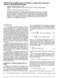
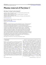
Figure 4: Multi-<strong>in</strong>put C-element.<br />
diagram<br />
(a) Transistor schematic, and (b) logical<br />
buffer stage allows the output low voltage to be low enough, s<strong>in</strong>ce the pull-down<br />
does not have to fight a passive pull-up. The lower output low <strong>in</strong>creases the<br />
noise marg<strong>in</strong>s considerably, with a small penalty <strong>in</strong> area and power.<br />
Super-buffers were used to buffer bus and control signals. To improve performance<br />
and noise marg<strong>in</strong> characteristics, a feed-back transistor was added,<br />
creat<strong>in</strong>g a "squeeze" buffer (see Figure l(c) [Br092]). Squeeze buffers allow the<br />
use of a stronger pull-up transistor, the feed-back transistor limits the output<br />
high voltage.<br />
To generate completion signals from the datapath, we use C-elements with a<br />
large number of <strong>in</strong>puts. They can be built from smaller C-elements connected <strong>in</strong><br />
a tree [Mar90], or, as <strong>in</strong> this case, as a s<strong>in</strong>gle logic gate (see Figure 4( a) and (b)).<br />
For a discussion on how this circuit works, see [Tie92J. Though a completion<br />
tree could be implemented with DCFL nor gates, it would be significantly slower<br />
and bigger than that of Figure 4(a). Completion detection is <strong>in</strong> sequence with<br />
the calculations performed by the datapath, and affects performance directly.<br />
It is critical to have an easy and fast way of generat<strong>in</strong>g the completion signal.<br />
4.2 Control Logic<br />
Control logic takes care of the sequenc<strong>in</strong>g of actions <strong>in</strong> the processor. After<br />
compilation, each control signal is assigned a set of "production rules", of the<br />
form:<br />
G -+ zi<br />
H -+ zl<br />
where G and H are boolean expressions <strong>in</strong> terms of the other signals. G and<br />
H do not have to be complementary. In fact, most operators <strong>in</strong> the control are<br />
7
a<br />
b<br />
d<br />
c<br />
z<br />
a<br />
b<br />
d<br />
c<br />
(a) d<br />
e<br />
d<br />
e<br />
z<br />
(b)<br />
z<br />
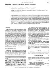
z a 1\ -,b v d 1\ c -+ z r<br />
-,d 1\ -'e -+ z 1<br />
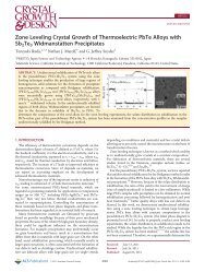
Figure 5: Dual rail implementation of control signals. (a) Transistor schematic,<br />
(b) logical diagram, and (c) production rules<br />
state hold<strong>in</strong>g, that is, G V H does not hold. There are different ways of giv<strong>in</strong>g<br />
a direct implementation of these production rules. One, Source Follower Fet<br />
Logic, is given <strong>in</strong> [Tie92]. In that paper, a systematic way of generat<strong>in</strong>g any<br />
operator described by production rules is presented. This method was applied<br />
<strong>in</strong> the design of the first GaAs microprocessor. However, it resulted <strong>in</strong> a circuit<br />
with a large power consumption (4 Watts) and modest performance (70 MIPS).<br />
For the second GaAs processor, a different approach was used. Each signal is<br />
implemented as a dual-rail encoded signal, always generat<strong>in</strong>g both positive and<br />
negative sense. S<strong>in</strong>ce most signals are state-hold<strong>in</strong>g, this is necessary anyway<br />
(we do not have dynamic logic available). On the up side, no <strong>in</strong>verters are<br />
necessary to generate the boolean expressions for the production rules. On<br />
the down side, comb<strong>in</strong>atorial gates require extra circuitry to generate dual-rail<br />
outputs, as do signals com<strong>in</strong>g <strong>in</strong> from the datapath.<br />
Figure 5 shows how a specific set of production rules are implemented <strong>in</strong> dualrail.<br />
Note the feed-back transistor on the outputs of the <strong>in</strong>dividual nor gates.<br />
These have the same function as the one on the "squeeze" buffer, allow<strong>in</strong>g us<br />
to use much stronger pull-up transistors.<br />
4.3 PLA's<br />
The power consumption of these circuits is relatively high, and the chips run hot<br />
(around 100°C). At this temperature, subthreshold currents of the pull-down<br />
8<br />
(c)
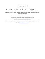
Figure 6: Example of a nor-nor PLA implemented with source-followers<br />
transistors may be strong enough to overpower the pull-ups; nor gates with<br />
more than 6 <strong>in</strong>puts are impractical, because the off current of 6 transistors is<br />
of the same order of magnitude as the on current of one transistor. Therefore,<br />
static DCFL PLAs cannot be used.<br />
We use a different structure for the PLAs <strong>in</strong> the processors. The nor planes<br />
are implemented with source followers, which can be turned off more effectively<br />
than the correspond<strong>in</strong>g DCFL structure (see Figure 6). A penalty is paid <strong>in</strong><br />
speed and power, but m<strong>in</strong>-terms with up to 10 <strong>in</strong>puts are realizable. The <strong>in</strong>ternal<br />
signals <strong>in</strong> the nor plane can switch rail to rail, giv<strong>in</strong>g much improved noise<br />
marg<strong>in</strong>s, and the level shift<strong>in</strong>g diodes help reverse-bias the pull-up transistors<br />
of the source-followers. Also, the ratio between the pull-up and pull-down <strong>in</strong><br />
the source-follower is close to 1, and the subthreshold current of the pull-down<br />
can better balance the pull-up.<br />
4.4 Register File<br />
The register file has 16 registers, 16 bits wide, and four ports, two for read and<br />
two for write. Register 0 is hard-wired to be read always as zero. Each register<br />
bit has a total of 12 transistors, four for the flip-flop and two extra for each<br />
port (see Figure 7). All ports are dual-rail, that is, data and <strong>in</strong>verted data<br />
is provided. Between reads and writes the buses are pre-charged to a neutral<br />
value, to prepare for the next operation, and reset the completion circuits.<br />
Read ports are implemented with a dual-ended sense amplifier (see Figure 8).<br />
This sense-amp detects a small difference between the true and false buses, and<br />
drives these buses strongly <strong>in</strong> opposite directions, us<strong>in</strong>g transistors T5, T4, and<br />
T1. To work properly, the register that is be<strong>in</strong>g read has to be selected some<br />
time prior to apply<strong>in</strong>g the sense signal. To this effect, the sense signal is derived<br />
from an "or" of all select signals for the given port.<br />
9
Figure 7: Register cell<br />
Figure 8: Sense amplifier, and pre-charge circuit for the register file<br />
When sense is off, transistors T8,T3 and T7,T2 pre-charge buses bT and b F<br />
to a value determ<strong>in</strong>ed by the ratio between T8 and T3 (T7 and T2). Transistor<br />
T6 further ensures the symmetry of the circuit.<br />
The buses are then buffered before go<strong>in</strong>g <strong>in</strong>to the datapath, to isolate the<br />
sense amplifier, and to restore the logic levels of the data signals.<br />
5 Results<br />
Us<strong>in</strong>g these techniques, several circuits have been designed, fabricated and<br />
tested on the HGAAS II and HGAAS III processes offered by Vitesse Semiconductors.<br />
Among them, small RAM's, register files, and two microprocessors.<br />
10
5.1 <strong>Asynchronous</strong> Static Memories<br />
We designed and fabricated two different types of static memories <strong>in</strong> GaAs.<br />
The first is a dual ported register file, 16 words of 4 bits/word. It was meant<br />
to provide a small amount of fast memory for the microprocessor to run test<br />
programs at full speed. Out of 30 bonded devices, 29 were functional. Access<br />
time is 5ns, and the chip dissipates 500m W at 2.2V.<br />
The second SRAM has 64 words of 4bits/word [Hom 1], and was designed<br />
as an <strong>in</strong>termediate step towards a larger memory to be used as a cache for the<br />
processor. All 30 bonded devices received were functional. The access time is<br />
3ns, <strong>in</strong>clud<strong>in</strong>g pad delays, and the chip dissipates 700m W at 2.3V<br />
This 64 x 4 memory was designed after the first processor, and <strong>in</strong>corporates<br />
several improvements derived from our experience with the earlier designs. Also,<br />
the circuits were carefully optimized for high speed and low power consumption.<br />
The performance obta<strong>in</strong>ed <strong>in</strong>dicates that the improvements envisioned for the<br />
next processor generation should be atta<strong>in</strong>able.<br />
5.2 <strong>Microprocessor</strong>s<br />
The first microprocessor design uses the circuits described <strong>in</strong> [Tie92J. The ma<strong>in</strong><br />
concern dur<strong>in</strong>g the design was to get around parameter variation problems and<br />
noise marg<strong>in</strong> considerations. This was achieved, but at the expense of power<br />
and performance. At 70 MIPS, the processor consumes 4 Watt.<br />
Several new ideas and circuits were <strong>in</strong>corporated <strong>in</strong> the new design, many of<br />
them presented <strong>in</strong> this paper. All of those circuits were fabricated and tested<br />
successfully.<br />
This design was extensively simulated with Hspice. The expected performance<br />
of this design is about 200 MIPS with a dissipation of 2 Watts, fabricated<br />
with the HGAAS III process. Power and speed predictions have been very<br />
accurate so far us<strong>in</strong>g the Hspice models. However, <strong>in</strong> this case the measured<br />
performance was only 100 MIPS. The causes are still under <strong>in</strong>vestigation. There<br />
is some evidence of fabrication problems, and underestimation of the parasite<br />
capacitances as extracted by the MAGIC layout program.<br />
6 Conclusions<br />
In the course of this project, we have designed a number of very different GaAs<br />
circuits. Most of them had very strict requirements, to overcome the limitations<br />
of GaAs. No general solution is given to synthesize all logic circuits <strong>in</strong> a design<br />
as big as a microprocessor. Instead, we found specific solutions to implement<br />
completion trees, control circuits, PLA's, registers, etc.<br />
The first GaAs microprocessor, though disappo<strong>in</strong>t<strong>in</strong>g <strong>in</strong> terms of performance,<br />
gave us <strong>in</strong>valuable experience <strong>in</strong> verify<strong>in</strong>g and test<strong>in</strong>g these circuits,<br />
as well as which were the <strong>in</strong>herent problems of each. Together with some of<br />
11
the RAM designs, it allowed us to prepare for a second mIcroprocessor, with<br />
considerable improvements <strong>in</strong> performance.<br />
<strong>An</strong>other factor affect<strong>in</strong>g performance is pad delay. So far we have used<br />
ECL levels on the outside, to be able to <strong>in</strong>terface to standard parts and simplify<br />
prototyp<strong>in</strong>g. Pad delays are <strong>in</strong> the order of Ins, mostly spent <strong>in</strong> level conversion;<br />
also, the padframe uses a considerable amount of power -close to 1A worst case<br />
for the processor-. This delay and power can be greatly reduced by design<strong>in</strong>g<br />
matched pad drivers and receivers <strong>in</strong> a system composed exclusively of GaAs<br />
parts. It would certa<strong>in</strong>ly be a requirement <strong>in</strong> the <strong>in</strong>terface with cache memory.<br />
Port<strong>in</strong>g the design of the orig<strong>in</strong>al CMOS microprocessor was almost as easy<br />
as expected. A few changes were necessary because of the complexity of register<br />
cells <strong>in</strong> the first GaAs version. These changes were carried over to the second<br />
processor to speed-up the redesign.<br />
All considered, the expected performance of the new microprocessor is satisfactory.<br />
At 50 MIPS/watt, it offers remarkable speed for the power consumption.<br />
Acknowledgments<br />
We are <strong>in</strong>debted to Marcel van der Goot for his help <strong>in</strong> generat<strong>in</strong>g high quality<br />
software support. Acknowledgment is due to Steve Burns and Pieter Hazew<strong>in</strong>dus,<br />
for their participation <strong>in</strong> the orig<strong>in</strong>al design, and many very useful comments<br />
and conversations, and H. Peter Hofstee for his collaboration <strong>in</strong> the design<br />
of asynchronous memories. Many thanks to Ray Milano of Vitesse Semiconductors,<br />
for <strong>in</strong>valuable help with the HGAAS technology, and to C<strong>in</strong>dy Hibbert<br />
and Metasoftware, for their help with Hspice.<br />
The research described <strong>in</strong> this paper was sponsored by the Defense Advanced<br />
Research Projects Agency, DARPA Order number 6202, and monitored by the<br />
Office of Naval Research under contract number N00014-87-K-0745.<br />
References<br />
[Br092]<br />
[Hoa78]<br />
[Hof91]<br />
[LB90]<br />
Richard Brown. Private communication, 1992.<br />
C.A.R. Hoare. Communicat<strong>in</strong>g sequential processes. Comm. ACM,<br />
21(8) :666-677, 1978.<br />
H. P. Hofstee. Deriv<strong>in</strong>g some asynchronous memories. Unpublished,<br />
1991.<br />
S. I. Long and S. E. Butner. <strong>Gallium</strong> <strong>Arsenide</strong> Digital Integrated<br />
Circuit Design. McGraw-Hill, New York, 1990.<br />
12
[Mar90] Ala<strong>in</strong> J. Mart<strong>in</strong>. Synthesis of asynchronous VLSI circuits. In<br />
J. Straunstrup, editor, Formal Methods for VLSI Design, pages 237-<br />
283. North-Holland, 1990.<br />
[Mar92] A. J. Mart<strong>in</strong>. <strong>Asynchronous</strong> datapaths and the design of an asynchronous<br />
adder. Formal Methods <strong>in</strong> System Design, 1(1):117-137,<br />
1992.<br />
[MBL +89] Ala<strong>in</strong> J. Mart<strong>in</strong>, Steven M. Burns, T. K. Lee, Drazen Borkovic, and<br />
Pieter J. Hazew<strong>in</strong>dus. The design of an asynchronous microprocessor.<br />
In Charles L. Seitz, editor, Advanced Research <strong>in</strong> VLSI: Proceed<strong>in</strong>gs<br />
of the Decennial Caltech Conference on VLSI, pages 351-373.<br />
MIT Press, 1989.<br />
[Tie92] J. A. Tierno. Design<strong>in</strong>g asynchronous circuits <strong>in</strong> <strong>Gallium</strong> <strong>Arsenide</strong>.<br />
CS-TR-92-19, California Institute of Technology, 1992.<br />
13