RA/8000, RA/8000/M - Norgren Pneumatics. Motion Control ...
RA/8000, RA/8000/M - Norgren Pneumatics. Motion Control ...
RA/8000, RA/8000/M - Norgren Pneumatics. Motion Control ...

Create successful ePaper yourself
Turn your PDF publications into a flip-book with our unique Google optimized e-Paper software.
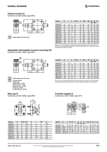
<strong>RA</strong>/<strong>8000</strong>, <strong>RA</strong>/<strong>8000</strong>/M<br />
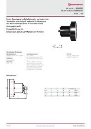
Centre trunnion H<br />
Conforms to ISO 15552, type MT4<br />
N/en 1.5.125.12<br />
2<br />
UW<br />
ø TD e 9<br />
L TL TM h 14<br />
2 Grease nippel up to Ø 125 mm<br />
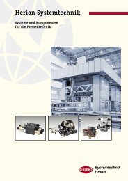
Adjustable intermediate trunnion mounting UH<br />
Conforms to ISO 15552, type MT4<br />
3<br />
2 Grease nippel up to Ø 125 mm<br />
3 Locking screws<br />
Torque max<br />
Ø 32 & 40 mm = 6 Nm<br />
Ø 50 & 63 mm = 10 Nm<br />
Ø 80 & 100 mm = 15 Nm<br />
Ø 125 mm = 25 Nm<br />
Ø 160 & 200 mm = 40 Nm<br />
2<br />
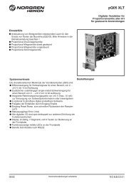
Rear eye R<br />
Conforms to ISO 15552, type MP4<br />
EW<br />
UW<br />
ø TD e 9<br />
L TL TM h 14<br />
FL<br />
L<br />
Style (R) Ø Ø CD H9 EW FL L MR kg<br />
QA/8032/27 32 10 25,8 22 13 9 0,09<br />
QA/8040/27 40 12 27,8 25 16 12 0,11<br />
QA/8050/27 50 12 31,7 27 17 12 0,17<br />
QA/8063/27 63 16 39,7 32 22 15 0,24<br />
QA/8080/27 80 16 49,7 36 22 15 0,37<br />
QA/8100/27 100 20 59,7 41 27 20 0,59<br />
QM/8125/27 125 25 69,7 50 33 25 3,20<br />
QM/8160/27 160 30 89,7 55 35,5 30 6,10<br />
QM/8200/27 200 30 89,7 60 37 30 6,80<br />
H 9<br />
CD<br />
MR<br />
R<br />
R<br />
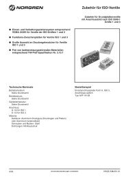
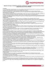
Trunnion support S<br />
Conforms to ISO 15552, type AT4<br />
Our policy is one of continued research and development. We therefore reserve the right to amend,<br />
without notice, the specifications given in this document.<br />
Type (H) Ø L R Ø TD e9 TL TM h14 UW XV XV kg<br />
min. max.<br />
QA/8032/28 32 20 1 12 12 50 50 66 80 0,16<br />
QA/8040/28 40 24 1,6 16 16 63 58 76 89 0,35<br />
QA/8050/28 50 28 1,6 16 16 75 70 82 98 0,65<br />
QA/8063/28 63 28 1,6 20 20 90 80 88 107 0,85<br />
QA/8080/28 80 28 1,6 20 20 110 100 97 123 1,20<br />
QA/8100/28 100 38 2 25 25 132 126 112 128 2,30<br />
QM/8125/28 125 50 2 25 25 160 152 136 154 3,30<br />
QM/8160/28 160 50 2,5 32 32 200 192 155 185 5,30<br />
QM/8200/28 200 50 2,5 32 32 250 240 170 200 9,40<br />
QM/8250/28 250 60 3,2 40 40 320 318 193 217 18,0<br />
QM/8320/28 320 70 3,2 50 50 400 400 215 245 30,0<br />
Note: Style ‘H’: These mountings are only supplied assembled complete with the cylinder. Unless otherwise<br />
specified, units will be supplied with dimension ‘XV’ plus half the stroke length. ‘XV’ = Distance from the piston<br />
rod shoulder to the centre of the mounting.<br />
Type (UH) Ø L R Ø TD e9 TL TM h14 UW XV XV kg<br />
min. max.<br />
QA/8032/40 32 20 1 12 12 50 50 66 80 0,16<br />
QA/8040/40 40 24 1,6 16 16 63 58 76 89 0,35<br />
QA/8050/40 50 28 1,6 16 16 75 70 82 98 0,65<br />
QA/8063/40 63 28 1,6 20 20 90 80 88 107 0,85<br />
QA/8080/40 80 28 1,6 20 20 110 100 97 123 1,20<br />
QA/8100/40 100 38 2 25 25 132 126 112 128 2,30<br />
QM/8125/40 125 50 2 25 25 160 152 136 154 3,30<br />
QM/8160/40 160 50 2,5 32 32 200 192 155 185 5,30<br />
QM/8200/40 200 50 2,5 32 32 250 240 170 200 9,40<br />
Style ‘UH’: It is most important that the locking screws which secure the mounting to the tie rod are tightened<br />
to the torque figures shown in the table below. For maximum energy input, consult our Technical Service.<br />
ø D 2<br />
A<br />
B 1<br />
ø D 3<br />
T 1<br />
H 2<br />
H 1<br />
ø D 1 H7<br />
Type (S) Ø A B1 B2 C Ø Ø Ø F x 45° H1 H2 T1 kg<br />
D1 H7 D2 D3<br />
QA/8032/41 32 32 46 18 10,5 12 6,6 11 1 30 15 6,8 0,10<br />
QA/8040/41 40/50 36 55 21 12 16 9 15 1,6 36 18 9 0,14<br />
QA/8063/41 63/80 42 65 23 13 20 11 18 1,6 40 20 11 0,18<br />
QA/8100/41 100/125 50 75 28,5 16 25 14 20 2 50 25 13 0,34<br />
QA/8160/41 160/200 60 92 39 21,5 32 18 26 2,5 60 25 15,5 1,90<br />
B 2<br />
C<br />
®<br />
F x 45°<br />
®<br />
2/08