RA/8000, RA/8000/M - Norgren Pneumatics. Motion Control ...
RA/8000, RA/8000/M - Norgren Pneumatics. Motion Control ...
RA/8000, RA/8000/M - Norgren Pneumatics. Motion Control ...

You also want an ePaper? Increase the reach of your titles
YUMPU automatically turns print PDFs into web optimized ePapers that Google loves.
Comprehensive range for the utmost versatility<br />
Conforms to ISO 15552<br />
(ISO 6431, VDMA 24562 and NFE 49-003-1)<br />
High performance, stability and reliability<br />
ideal for the demands of today<br />
Supplied complete with piston rod locknut<br />
Comprehensive range of standard mountings<br />
2/08<br />
®<br />
Technical data<br />
Medium:<br />
Compressed air, filtered, lubricated or non-lubricated<br />
Standard:<br />
ISO 15552<br />
Operation:<br />
Double acting<br />
<strong>RA</strong>/<strong>8000</strong>: adjustable cushioning<br />
<strong>RA</strong>/<strong>8000</strong>/M: magnetic piston, adjustable cushioning<br />
Operating pressure:<br />
1 to 16 bar (1 to 10 bar for Ø 250 and 320 mm)<br />
Operating temperature:<br />
-20 to +80°C max. (Ø 32 to 125 mm)<br />
-10 to +80°C max. (Ø 160 to 320 mm)<br />
(consult our Technical Service for use below +2°C)<br />
Cylinder diameters:<br />
32, 40, 50, 63, 80, 100, 125, 160, 200, 250, 320 mm<br />
Strokes:<br />
Standard: see page 3<br />
Non-standard strokes (10 to 3000 mm) available<br />
Materials:<br />
Barrel: Anodised aluminium<br />
End covers: Pressure diecast aluminium<br />
(Ø 200 to 320 mm gravity cast aluminium)<br />
Piston rod: Stainless steel (Martensitic)<br />
Piston rod seals: Polyurethane<br />
(Ø 125 to 320 mm nitrile rubber)<br />
Piston seals: Polyurethane<br />
(Ø 125 to 320 mm nitrile rubber)<br />
‘O’-rings: Nitrile rubber<br />
®<br />
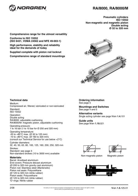
Non-magnetic piston<br />
Our policy is one of continued research and development. We therefore reserve the right to amend,<br />
without notice, the specifications given in this document.<br />
<strong>RA</strong>/<strong>8000</strong>, <strong>RA</strong>/<strong>8000</strong>/M<br />
Pneumatic cylinders<br />
ISO 15552<br />
Non-magnetic and magnetic piston<br />
Double acting<br />
Ø 32 to 320 mm<br />
Ordering information<br />
See page 5<br />
Mountings and Switches<br />
See page 4 and 5<br />
Alternative variants<br />
Single acting cylinder see page N/en 1.4.101<br />
Guide units<br />
See page N/en 1.10.021<br />
Magnetic piston<br />
N/en 1.5.125.01
<strong>RA</strong>/<strong>8000</strong>, <strong>RA</strong>/<strong>8000</strong>/M<br />
Cylinder variants<br />
Symbol Type Symbol Type Beschreibung Dimensions<br />
H T C S<br />
non-magnetic<br />
piston H T C S<br />
magnetic<br />
piston Page<br />
• • • • <strong>RA</strong>/<strong>8000</strong> • • • • <strong>RA</strong>/<strong>8000</strong>/M Standard cylinder 7<br />
For combinations of cylinder variants consult our Technical Service.<br />
For types H*1), T, and C, S see options selector<br />
*1) type H: Ø 32 to 100 mm<br />
Warning<br />
N/en 1.5.125.02<br />
• • <strong>RA</strong>/<strong>8000</strong>/W1 • • <strong>RA</strong>/<strong>8000</strong>/W2 Cylinder with special wiper/seal 7<br />
suitable for applications with Arizona sand, cement,<br />
plaster (stucco), hoar-frost or ice (Ø 32 to 125)<br />
• • <strong>RA</strong>/<strong>8000</strong>/X1 • • <strong>RA</strong>/<strong>8000</strong>/X2 Low friction cylinders, operating pressure: 1 to 10 bar 7<br />
Medium: compressed air, filtered and non-lubricated<br />
recommended (Ø 32 to 200)<br />
• • • • <strong>RA</strong>/<strong>8000</strong>/IU • • • • <strong>RA</strong>/<strong>8000</strong>/MU Cylinder with extended piston rod 7<br />
• • <strong>RA</strong>/<strong>8000</strong>/W5 • • <strong>RA</strong>/<strong>8000</strong>/W6 Cylinder with extended piston rod and special wiper/ 7<br />
seal, for applications with Arizona sand, cement,<br />
plaster (stucco), hoar-frost or ice (Ø 32 to 125)<br />
• • • <strong>RA</strong>/<strong>8000</strong>/G • • • <strong>RA</strong>/<strong>8000</strong>/MG Cylinder with piston rod bellows 8<br />
• • • <strong>RA</strong>/<strong>8000</strong>/W • • • <strong>RA</strong>/<strong>8000</strong>/MW Cylinder owithout cushioning 7<br />
• • <strong>RA</strong>/<strong>8000</strong>/X3 • • <strong>RA</strong>/<strong>8000</strong>/X4 Low friction without cushioning, 7<br />
Operating pressure: 1 to 10 bar,<br />
Medium: compressed air, filtered and non-lubricated<br />
recommended (Ø 32 to 200)<br />
• • • • <strong>RA</strong>/<strong>8000</strong>/J • • • • <strong>RA</strong>/<strong>8000</strong>/JM Cylinder with double ended piston rod 8<br />
• • <strong>RA</strong>/<strong>8000</strong>/W3 • • <strong>RA</strong>/<strong>8000</strong>/W4 Cylinder with double ended piston rod and special wiper/ 8<br />
seal, suitable for applications with Arizona sand, cement,<br />
plaster (stucco), hoar-frost or ice (Ø 32 to 125 mm)<br />
• • • <strong>RA</strong>/<strong>8000</strong>/IT • • • <strong>RA</strong>/<strong>8000</strong>/MT Four position cylinder (Ø 32 to 200 mm) 8<br />
<strong>RA</strong>/<strong>8000</strong>/N1 <strong>RA</strong>/<strong>8000</strong>/N2 Cylinder with non-rotating piston rod 8<br />
(Ø 32 to 100 mm)<br />
• • <strong>RA</strong>/<strong>8000</strong>/L2 • • <strong>RA</strong>/<strong>8000</strong>/L4 Cylinder with locking unit (passive). 9<br />
Locking is achieved by spring force on removal of the<br />
signal to the unit. Operating Pressure for locking unit:<br />
4 to 10 bar (Ø 32 to 125 mm)<br />
These products are intended for use in industrial compressed air systems<br />
only. Do not use these products where pressures and temperatures<br />
can exceed those listed under ‘Technical Data’.<br />
Before using these products with fluids other than those specified,<br />
for non-industrial applications, life-support systems, or other applications<br />
not within published specifications, consult NORGREN.<br />
Through misuse, age, or malfunction, components used<br />
in fluid power systems can fail in various modes.<br />
Our policy is one of continued research and development. We therefore reserve the right to amend,<br />
without notice, the specifications given in this document.<br />
The system designer is warned to consider the failure modes of<br />
all component parts used in fluid power systems and to provide adequate<br />
safeguards to prevent personal injury or damage to equipment<br />
in the event of such failure.<br />
System designers must provide a warning to end users in<br />
the system instructional manual if protection against a failure<br />
mode cannot be adequately provided.<br />
System designers and end users are cautioned to review specific<br />
warnings found in instruction sheets packed and shipped with<br />
these products.<br />
®<br />
®<br />
2/08
®<br />
Options selector<br />
2/08<br />
®<br />
Special variants Substitute<br />
High temperature version: 150°C max. T<br />
Piston rod material Substitute<br />
Stainless steel (martensitic) R<br />
Hard chromium plated C<br />
Stainless steel (austenitic) S<br />
Cylinder Ø (mm) Substitute<br />
032, 040, 050, 063, 080, 100, 125, 160, 200, 250, 320<br />
Variants (magnetic piston) Substitute<br />
Standard M<br />
Special wiper/seal W2<br />
Low friction X2<br />
Piston rod bellow MG<br />
Without cushioning MW<br />
Without cushioning, low friction X4<br />
Double ended piston rod JM<br />
Double ended piston rod, special wiper/seal W4<br />
Four position MT<br />
Non-rotating piston rod N2<br />
Locking unit L4<br />
Extended piston rod MU<br />
Extended piston rod, special wiper/seal W6<br />
**A/8***/MU/****/***<br />
/W6/ Extension (mm)<br />
Standard strokes<br />
Cylinder Strokes (mm)<br />
Ø 25 50 80 100 125 160 200 250 320 400 500<br />
32 • • • • • • • • • • •<br />
40 • • • • • • • • • • •<br />
50 • • • • • • • • • • •<br />
63 • • • • • • • • • • •<br />
80 • • • • • • • • • • •<br />
100 • • • • • • • • • • •<br />
125 • • • • • • • • • • •<br />
160 • • • • • • • • • • •<br />
200 • • • • • • • • • • •<br />
250 • • • • • • • • • • •<br />
320 • • • • • • • • • • •<br />
˙˙A/8˙˙˙/˙˙/˙˙˙˙<br />
Our policy is one of continued research and development. We therefore reserve the right to amend,<br />
without notice, the specifications given in this document.<br />
Strokes (mm)<br />
3000 max.<br />
<strong>RA</strong>/<strong>8000</strong>, <strong>RA</strong>/<strong>8000</strong>/M<br />
Variants (non-magnetic piston) Substitute<br />
Standard<br />
Special wiper/seal W1<br />
Low friction X1<br />
Piston rod bellow G<br />
Without cushioning W<br />
Without cushioning, low friction X3<br />
Double ended piston rod J<br />
Double ended piston rod, special wiper/seal W3<br />
Four position IT<br />
Non-rotating piston rod N1<br />
Locking unit L2<br />
Extended piston rod IU<br />
Extended piston rod, special wiper/seal W5<br />
**A/8***/IU/****/***<br />
/W5/ Extension (mm)<br />
Note: If option is not required, disregard option position within<br />
part number, eg. <strong>RA</strong>/8100/100. For combinations of cylinder<br />
variants consult our Technical Service.<br />
Please note that heat resistant seals are not available for all<br />
variants.<br />
This options selector explains only the cylinder variants.<br />
Additional variants/options can not be derived from.<br />
N/en 1.5.125.03
<strong>RA</strong>/<strong>8000</strong>, <strong>RA</strong>/<strong>8000</strong>/M<br />
Mountings<br />
N/en 1.5.125.04<br />
Style A Style AK Style B, G Style C Style D Style D2 Style F Style FH Style H<br />
Cylinder<br />
10<br />
18<br />
1<br />
2<br />
5<br />
7<br />
15<br />
9<br />
11<br />
Ø Page 10 Page 10 Page 10 Page 10 Page 11 Page 11 Page 11 Page 11 Page 12<br />
32 QM/8032/35 QM/8025/38 QA/8032/22 QA/8032/21 QA/8032/23 QA/8032/42 QM/8025/25 QA/8032/34 QA/8032/28<br />
40 QM/8032/35 QM/8040/38 QA/8040/22 QA/8040/21 QA/8040/23 QA/8040/42 QM/8040/25 QA/8040/34 QA/8040/28<br />
50 QM/8050/35 QM/8050/38 QA/8050/22 QA/8050/21 QA/8050/23 QA/8050/42 QM/8050/25 QA/8050/34 QA/8050/28<br />
63 QM/8050/35 QM/8050/38 QA/8063/22 QA/8063/21 QA/8063/23 QA/8063/42 QM/8050/25 QA/8063/34 QA/8063/28<br />
80 QM/8080/35 QM/8080/38 QA/8080/22 QA/8080/21 QA/8080/23 QA/8080/42 QM/8080/25 QA/8080/34 QA/8080/28<br />
100 QM/8080/35 QM/8080/38 QA/8100/22 QA/8100/21 QA/8100/23 QA/8100/42 QM/8080/25 QA/8100/34 QA/8100/28<br />
125 QM/8125/35 QM/8125/38 QM/8125/22 QM/8125/21 QM/8125/23 QA/8125/42 QM/8125/25 QA/8125/34 QM/8125/28<br />
160 QM/8160/35 QM/8160/38 QM/8160/22 QM/8160/21 QM/8160/23 QA/8160/42 QM/8160/25 – QM/8160/28<br />
200 QM/8160/35 QM/8160/38 QM/8200/22 QM/8200/21 QM/8200/23 QA/8200/42 QM/8160/25 – QM/8200/28<br />
250 QM/8250/35 – QM/8250/22 QM/8250/21 QM/8250/23 – QM/8250/25 – QM/8250/28<br />
320 QM/8320/35 – QM/8320/22 QM/8320/21 QM/8320/23 – QM/8320/25 – QM/8320/28<br />
Style R Style S Style SS Style SW Style UF Style UH Style UR Style US<br />
Cylinder<br />
3<br />
12<br />
16<br />
6<br />
17<br />
11<br />
4<br />
8<br />
Ø Page 12 Page 12 Page 13 Page 13 Page 13 Page 12 Page 13 Page 13<br />
32 QA/8032/27 QA/8032/41 M/P19931 M/P19493 QM/8025/32 QA/8032/40 QA/8032/33 M/P40310<br />
40 QA/8040/27 QA/8040/41 M/P19932 M/P19494 QM/8040/32 QA/8040/40 QA/8040/33 M/P40311<br />
50 QA/8050/27 QA/8040/41 M/P19933 M/P19495 QM/8050/32 QA/8050/40 QA/8050/33 M/P40312<br />
63 QA/8063/27 QA/8063/41 M/P19934 M/P19496 QM/8050/32 QA/8063/40 QA/8063/33 M/P40313<br />
80 QA/8080/27 QA/8063/41 M/P19935 M/P19497 QM/8080/32 QA/8080/40 QA/8080/33 M/P40314<br />
100 QA/8100/27 QA/8100/41 M/P19936 M/P19498 QM/8080/32 QA/8100/40 QA/8100/33 M/P40315<br />
125 QM/8125/27 QA/8100/41 M/P19937 M/P19499 QM/8125/32 QM/8125/40 QM/8125/33 M/P71355<br />
160 QM/8160/27 QA/8160/41 M/P19938 M/P19679 QM/8160/32 QM/8160/40 QM/8160/33 M/P71356<br />
200 QM/8200/27 QA/8160/41 M/P19939 M/P19683 QM/8160/32 QM/8200/40 QM/8200/33 M/P71357<br />
250 – – – M/P19446 QM/8250/32 – QM/8250/33 –<br />
320 – – – M/P19447 QM/8320/32 – QM/8320/33 –<br />
Brackets for switches Guide unit<br />
*1) *2) *3)<br />
Cylinder 23<br />
19<br />
Ø Page 14 Page 14 Page 14 See datasheet 1.10.021<br />
32 QM/27/2/1 QM/31/032/22 QM/140/010/22<br />
40 QM/27/2/1 QM/31/032/22 QM/140/010/22<br />
50 QM/27/2/1 QM/31/032/22 QM/140/010/22<br />
63 QM/27/2/1 QM/31/032/22 QM/140/010/22<br />
80 QM/27/2/1 QM/31/080/22 QM/140/010/22<br />
100 QM/27/2/1 QM/31/080/22 QM/140/010/22<br />
125 QM/27/2/1 QM/31/080/22 –<br />
160 QM/27/2/1 QM/31/160/22 –<br />
200 QM/27/2/1 QM/31/160/22 –<br />
250 – QM/31/250/22 –<br />
320<br />
*1) M/50<br />
– QM/31/320/22 –<br />
*2) TQM/31, QM/32 oder QM/132<br />
*3) QM/140<br />
Our policy is one of continued research and development. We therefore reserve the right to amend,<br />
without notice, the specifications given in this document.<br />
®<br />
®<br />
2/08
®<br />
2/08<br />
18<br />
17<br />
19<br />
16<br />
®<br />
15<br />
1<br />
2<br />
20<br />
23<br />
Our policy is one of continued research and development. We therefore reserve the right to amend,<br />
without notice, the specifications given in this document.<br />
3<br />
4<br />
5<br />
11<br />
7<br />
<strong>RA</strong>/<strong>8000</strong>, <strong>RA</strong>/<strong>8000</strong>/M<br />
12<br />
6<br />
10<br />
8<br />
9<br />
N/en 1.5.125.05
<strong>RA</strong>/<strong>8000</strong>, <strong>RA</strong>/<strong>8000</strong>/M<br />
Switches<br />
N/en 1.5.125.06<br />
With cable With connector<br />
Cable/<br />
Type Voltage Current Temperature LED Features Connector Cable Cable with<br />
Reed Solid state V a.c. V d.c. max. °C length type Connector Datasheet<br />
M/50/LSU/*V – 10 to 240 10 to 170 180 mA -20 to +80 • – 2, 5, 10 m PVC 2 x 0,25 – N/UK 4.3.005<br />
M/50/LSU/5U – 10 to 240 10 to 170 180 mA -20 to +80 • – 5 m PUR 2 x 0,25 – N/UK 4.3.005<br />
TM/50/<strong>RA</strong>U/2S – 10 to 240 10 to 170 180 mA -20 to +150 – – 2 m Silicone 2 x 0,25 – N/UK 4.3.005<br />
M/50/<strong>RA</strong>C/5V – 10 to 240 10 to 170 180 mA -20 to +80 – Changeover 5 m PVC 3 x 0,25 – N/UK 4.3.005<br />
M/50/LSU/CP – 10 to 60 10 to 75 180 mA -20 to +80 • Plug M8x1 5 m PVC 3 x 0,25 M/P73001/5 N/UK 4.3.005<br />
– M/50/EAP/*V – 10 to 30 150 mA -20 to +80 • PNP 2, 5, 10 m PVC 3 x 0,25 – N/UK 4.3.007<br />
– M/50/EAP/CP – 10 to 30 150 mA -20 to +80 • PNP, Plug M8x1 5 m PVC 3 x 0,25 M/P73001/5 N/UK 4.3.007<br />
– M/50/EAP/CC – 10 to 30 150 mA -20 to +80 • PNP, Plug M12x1 5 m PVC 3 x 0,25 M/P34614/5 N/UK 4.3.007<br />
– M/50/EAN/*V – 10 to 30 150 mA -20 to +80 • NPN 2, 5, 10 m PVC 3 x 0,25 – N/UK 4.3.007<br />
– M/50/EAN/CP – 10 to 30 150 mA -20 to +80 • NPN, Plug M8x1 5 m PVC 3 x 0,25 M/P73001/5 N/UK 4.3.007<br />
* Please insert cable length<br />
Further information (technical data, cable material, dimensions) see datasheet.<br />
Magnetically operated switches<br />
With cable With connector (M12x1)<br />
Type Voltage Current Temperature LED Features<br />
Cable/<br />
Connector Cable Cable with<br />
Reed Solid state V a.c. V d.c. max. °C length Type Connector Datasheet<br />
TQM/31/* – 10 to 240 10 to 240 2 A -20 to +150 – High temperature 5 m Silicone 2x0,75 – N/UK 4.3.021<br />
QM/32/* – 10 to 240 10 to 240 1 A -20 to +80 • – 2, 5, 10 m PVC 2 x 0,75 – N/UK 4.3.021<br />
QM/32/5/PU – 10 to 240 10 to 240 1 A -20 to +80 • – 5 m PUR 2 x 0,75 – N/UK 4.3.021<br />
QM/32/P – 10 to 240 10 to 240 1 A -20 to +80 • – 5 m PVC 3 x 0,34 M/P34692/5 N/UK 4.3.021<br />
– QM/132/* – 10 to 30 0,2 A -20 to +80 • PNP 2, 5, 10 m PVC 3 x 0,35 – N/UK 4.3.025<br />
– QM/132/5/PU – 10 to 30 0,2 A -20 to +80 • PNP 5 m PUR 3 x 0,34 – N/UK 4.3.025<br />
– QM/132/P – 10 to 30 0,2 A -20 to +80 • PNP 5 m PVC 3 x 0,34 M/P34692/5 N/UK 4.3.025<br />
– QM/132/E/5 – 10 to 30 0,2 A -20 to +80 • Pulse stretcher 5 m PVC 3 x 0,35 – N/UK 4.3.025<br />
– QM/132/S/5 20 to 250 – 300 mA -20 to +80 • – 5 m PVC 2 x 0,75 – N/UK 4.3.025<br />
* Please insert cable length<br />
Further information (technical data, cable material, dimensions) see data sheet.<br />
Pneumatically operated switch<br />
Type<br />
Pneumatic Operating pressure Flow rate Orifice size Temperature LED Connections Datasheet<br />
QM/140 2 to 6 bar 40 l/min 2 mm +60°C • for 3 mm I/D tubing N/UK 4.3.061<br />
* Please insert cable length<br />
Further information (technical data, cable material, dimensions) see data sheet.<br />
Ordering information<br />
Cylinders<br />
To order a basic 80 mm bore<br />
magnetic piston cylinder with a 50 mm stroke<br />
quote: <strong>RA</strong>/8080/M/50<br />
Mountings<br />
To order a front flange mounting<br />
style ‘G’ for 80 mm bore cylinder<br />
quote: QA/8080/22<br />
Switches<br />
To order a reed switch with LED<br />
and 2 m cable length<br />
quote: M/50/LSU/2V<br />
Brackets for switches<br />
To order a bracket for magnetically<br />
operated switches M/50/LSU/2V;<br />
80 mm bore cylinder<br />
quote: QM/27/2/1<br />
Our policy is one of continued research and development. We therefore reserve the right to amend,<br />
without notice, the specifications given in this document.<br />
®<br />
®<br />
2/08
®<br />
2/08<br />
®<br />
Theoretical forces, cushioning, air consumption<br />
Basic dimensions<br />
<strong>RA</strong>/<strong>8000</strong>, <strong>RA</strong>/<strong>8000</strong>/M – Standard cylinder<br />
Our policy is one of continued research and development. We therefore reserve the right to amend,<br />
without notice, the specifications given in this document.<br />
<strong>RA</strong>/<strong>8000</strong>, <strong>RA</strong>/<strong>8000</strong>/M<br />
Type Cylinder Theoretical forces (N) at 6 bar Cushion length Initial cushion Air consumption (l/cm stroke) at 6 bar<br />
Ø outstroke instroke (mm) volume (cm 3) outstroke instroke<br />
<strong>RA</strong>/8032/. 32 482 414 19 12,3 0,056 0,048<br />
<strong>RA</strong>/8040/. 40 754 633 22 20,7 0,088 0,074<br />
<strong>RA</strong>/8050/. 50 1178 990 24 36 0,137 0,114<br />
<strong>RA</strong>/8063/. 63 1870 1680 24 64 0,218 0,195<br />
<strong>RA</strong>/8080/. 80 3016 2722 27 116 0,35 0,32<br />
<strong>RA</strong>/8100/. 100 4710 4416 34 242 0,55 0,51<br />
<strong>RA</strong>/8125/. 125 7363 6882 41 451 0,86 0,79<br />
<strong>RA</strong>/8160/. 160 12064 11310 45 816 1,41 1,32<br />
<strong>RA</strong>/8200/. 200 18840 18090 45 1324 2,20 2,10<br />
<strong>RA</strong>/8250/. 250 29436 28236 60 2900 3,44 3,30<br />
<strong>RA</strong>/8320/. 320 48228 47292 65 5200 5,63 5,41<br />
# stroke<br />
1<br />
ø B e 11<br />
KK<br />
cushion screw<br />
AM<br />
KW<br />
A<br />
KV SW<br />
B<br />
WH<br />
L8 + #<br />
L 2 G<br />
G<br />
VD PL<br />
PL<br />
L 12 EE 1<br />
EE<br />
ø 80 ... 320 mm<br />
L 9<br />
BG<br />
BG<br />
Type Ø AM AP Ø Be11 Ø BAe11 BG BH ❑ E EE G KK KV KW L2<br />
<strong>RA</strong>/8032/. 32 22 3,5 30 30 18 6 47 G 1/8 27,5 M10x1,25 17 5 20<br />
<strong>RA</strong>/8040/. 40 24 4,5 35 35 18 6 53 G 1/4 32 M12x1,25 19 6 22<br />
<strong>RA</strong>/8050/. 50 32 6 40 40 18 8 65 G 1/4 31 M16x1,5 24 8 27<br />
<strong>RA</strong>/8063/. 63 32 10 45 45 17,5 8 75 G 3/8 33 M16x1,5 24 8 29<br />
<strong>RA</strong>/8080/. 80 40 8,5 45 45 21,5 19 95 G 3/8 33 M20x1,5 30 10 33<br />
<strong>RA</strong>/8100/. 100 40 9 55 55 21,5 19 115 G 1/2 37 M20x1,5 30 10 36<br />
<strong>RA</strong>/8125/. 125 54 10 60 60 30 24 140 G 1/2 46 M27x2 41 13,5 45<br />
<strong>RA</strong>/8160/. 160 72 18 65 65 28,5 32 183,5 G 3/4 50 M36x2 55 18 58<br />
<strong>RA</strong>/8200/. 200 72 18 75 75 28,5 32 224 G 3/4 50 M36x2 55 18 67<br />
<strong>RA</strong>/8250/. 250 84 22,5 90 90 35 36 280 G 1 58 M42x2 65 21 80<br />
<strong>RA</strong>/8320/. 320 96 22,5 110 110 30 46 350 G 1 60 M48x2 75 24 90<br />
Type Ø L8 L9 L12 Ø MMh 9 PL ❑ R RT SW VA VD WH at 0 mm per 25 mm<br />
<strong>RA</strong>/8032/. 32 94 4 6 12 13 32,5 M 6 10 3 6 26 0,51 kg 0,06 kg<br />
<strong>RA</strong>/8040/. 40 105 4 6,5 16 15 38 M 6 13 3,5 6 30 0,80 kg 0,08 kg<br />
<strong>RA</strong>/8050/. 50 106 5 8 20 18,5 46,5 M 8 17 3,5 6 37 1,33 kg 0,12 kg<br />
<strong>RA</strong>/8063/. 63 121 5 8 20 19 56,5 M 8 17 4 6 37 1,80 kg 0,13 kg<br />
<strong>RA</strong>/8080/. 80 128 - 10 25 19 72 M 10 22 4 6 46 3,25 kg 0,20 kg<br />
<strong>RA</strong>/8100/. 100 138 - 10 25 18 89 M 10 22 4 6 51 4,81 kg 0,23 kg<br />
<strong>RA</strong>/8125/. 125 160 - 13 32 22,5 110 M 12 27 6 15,5 65 8,00 kg 0,33 kg<br />
<strong>RA</strong>/8160/. 160 180 - 16 40 21 140 M 16 36 4 15 80 14,9 kg 0,55 kg<br />
<strong>RA</strong>/8200/. 200 180 - 16 40 21 175 M 16 36 5 15 95 21,7 kg 0,60 kg<br />
<strong>RA</strong>/8250/. 250 200 - 20 50 29 220 M 20 41 7 13 105 32,6 kg 0,92 kg<br />
<strong>RA</strong>/8320/. 320 220 - 24 63 30 270 M 24 55 7 13 120 59,8 kg 1,46 kg<br />
RT<br />
RT<br />
VA<br />
AP<br />
ø BA e 11<br />
MM h 9<br />
A - B<br />
E<br />
R<br />
BH<br />
BH<br />
N/en 1.5.125.07
<strong>RA</strong>/<strong>8000</strong>, <strong>RA</strong>/<strong>8000</strong>/M<br />
Alternative variants<br />
<strong>RA</strong>/<strong>8000</strong>/J, <strong>RA</strong>/<strong>8000</strong>/JM – Cylinder with double ended piston rod<br />
Type Ø ZM L8<br />
<strong>RA</strong>/8032/J./. 32 146 94<br />
<strong>RA</strong>/8040/J./. 40 165 105<br />
<strong>RA</strong>/8050/J./. 50 180 106<br />
<strong>RA</strong>/8063/J./. 63 195 121<br />
<strong>RA</strong>/8080/J./. 80 220 128<br />
<strong>RA</strong>/8100/J./. 100 240 138<br />
<strong>RA</strong>/8125/J./. 125 290 160<br />
<strong>RA</strong>/8160/J./. 160 340 180<br />
<strong>RA</strong>/8200/J./. 200 370 180<br />
<strong>RA</strong>/8250/J./. 250 410 200<br />
<strong>RA</strong>/8320/J./. 320 460 220<br />
<strong>RA</strong>/<strong>8000</strong>/N1, <strong>RA</strong>/<strong>8000</strong>/N2 – Cylinder with non-rotating piston rod<br />
Type Ø Torque<br />
max.<br />
(Nm)<br />
<strong>RA</strong>/8032/N./. 32 10 0,5<br />
<strong>RA</strong>/8040/N./. 40 13 1,0<br />
<strong>RA</strong>/8050/N./. 50 16 1,5<br />
<strong>RA</strong>/8063/N./. 63 16 1,5<br />
<strong>RA</strong>/8080/N./. 80 16 2,5<br />
<strong>RA</strong>/8100/N./. 100 21 2,5<br />
<strong>RA</strong>/<strong>8000</strong>/IT, <strong>RA</strong>/<strong>8000</strong>/MT – Four position cylinder<br />
Type Ø L 8 L 10 L 11<br />
<strong>RA</strong>/8032/.T/. 32 94 247 7<br />
<strong>RA</strong>/8040/.T/. 40 105 278 8<br />
<strong>RA</strong>/8050/.T/. 50 106 294 8<br />
<strong>RA</strong>/8063/.T/. 63 121 325 9<br />
<strong>RA</strong>/8080/.T/. 80 128 357 9<br />
<strong>RA</strong>/8100/.T/. 100 138 387 9<br />
<strong>RA</strong>/8125/.T/. 125 160 462 12<br />
<strong>RA</strong>/8160/.T/. 160 180 532 12<br />
<strong>RA</strong>/8200/.T/. 200 180 560 10<br />
# stroke<br />
<strong>RA</strong>/<strong>8000</strong>/G und <strong>RA</strong>/<strong>8000</strong>/MG – Cylinder with piston rod bellows<br />
Type Ø Ø A Max. Piston rod<br />
stroke extension B<br />
per for for<br />
bellow first further<br />
bellow bellow<br />
<strong>RA</strong>/8032/.G/.. 32 40 60 30 25<br />
<strong>RA</strong>/8040/.G/.. 40 63 145 50 32<br />
<strong>RA</strong>/8050/.G/.. 50 63 145 40 32<br />
<strong>RA</strong>/8063/.G/.. 63 63 145 40 32<br />
<strong>RA</strong>/8080/.G/.. 80 80 250 50 45<br />
<strong>RA</strong>/8100/.G/.. 100 80 250 50 45<br />
<strong>RA</strong>/8125/.G/.. 125 80 250 50 45<br />
<strong>RA</strong>/8160/.G/.. 160 116 350 70 60<br />
<strong>RA</strong>/8200/.G/.. 200 116 350 70 60<br />
<strong>RA</strong>/8250/.G/.. 250 116 350 70 60<br />
<strong>RA</strong>/8320/.G/.. 320 143 500 110 100<br />
N/en 1.5.125.08<br />
øA<br />
A<br />
B<br />
L 8 + #1<br />
L 10 + #1 + #2<br />
L11<br />
L 8 + #2<br />
Our policy is one of continued research and development. We therefore reserve the right to amend,<br />
without notice, the specifications given in this document.<br />
B<br />
ZM + 2 x #<br />
L 8 + #<br />
®<br />
A - B<br />
# Hub<br />
®<br />
2/08
®<br />
2/08<br />
®<br />
<strong>RA</strong>/<strong>8000</strong>/L2, <strong>RA</strong>/<strong>8000</strong>/L4 – Cylinder with locking unit (passive)<br />
ø B e 11<br />
VD AD<br />
AF<br />
WH AH<br />
AB<br />
AE<br />
AG<br />
Our policy is one of continued research and development. We therefore reserve the right to amend,<br />
without notice, the specifications given in this document.<br />
<strong>RA</strong>/<strong>8000</strong>, <strong>RA</strong>/<strong>8000</strong>/M<br />
# stroke<br />
Type Ø AB AD AE AF AG AH Ø AJ AK AL AM AN<br />
<strong>RA</strong>/8032/L./. 32 32 12 8 40 4,2 48 25 M 5 16 59 8<br />
<strong>RA</strong>/8040/L./. 40 35,5 12 10 46 4,5 55 24 M 5 21 61,5 10<br />
<strong>RA</strong>/8050/L./. 50 49 16 15 54 11,5 70 30 M 6 24 75 12<br />
<strong>RA</strong>/8063/L./. 63 49 15 15 55 7,5 70 38 M 8 32 86 12<br />
<strong>RA</strong>/8080/L./. 80 62 16 16 70 10 90 53 M 8 44 119 16<br />
<strong>RA</strong>/8100/L./. 100 65 18 16 70 10 92 48 M 8 60 119 16<br />
<strong>RA</strong>/8125/L./. 125 85 27 25 95 11 122 65 M 10 75 140 20<br />
Type Ø Ø B e11 E E 1 EE L 8 ❏ R RT VD WH Locking force<br />
<strong>RA</strong>/8032/L./. 32 30 48 50 M 5 94 32,5 M 6 10 16 600 N<br />
<strong>RA</strong>/8040/L./. 40 35 56 58 G 1/8 105 38 M 6 10 18 1000 N<br />
<strong>RA</strong>/8050/L./. 50 40 68 70 G 1/8 106 46,5 M 8 12 22 1500 N<br />
<strong>RA</strong>/8063/L./. 63 45 82 85 G 1/8 121 56,5 M 8 12 20 2200 N<br />
<strong>RA</strong>/8080/L./. 80 45 100 105 G 1/8 128 72 M 10 20 33 5000 N<br />
<strong>RA</strong>/8100/L./. 100 55 120 130 G 1/8 138 89 M 10 23 38 5000 N<br />
<strong>RA</strong>/8125/L./. 125 60 140 150 G 1/8 160 110 M 12 32 65 7000 N<br />
L 8 + #<br />
AM<br />
AN<br />
Ø AJ<br />
EE<br />
AK<br />
AL<br />
E<br />
RT<br />
R<br />
E1<br />
N/en 1.5.125.09
<strong>RA</strong>/<strong>8000</strong>, <strong>RA</strong>/<strong>8000</strong>/M<br />
Mountings<br />
Front or rear stud mounting A<br />
Conforms to ISO 15552, type MX1<br />
Style (A) Ø BB DD TG kg<br />
QM/8032/35 32/40 17 M6 32,5/38 0,02<br />
QM/8050/35 50/63 23 M8 46,5/56,5 0,05<br />
QM/8080/35 80/100 28 M10 72/89 0,08<br />
QM/8125/35 125 34 M12 110 0,14<br />
QM/8160/35 160/200 42 M16 140/175 0,31<br />
QM/8250/35 250 50 M20 220 0,92<br />
QM/8320/35 320 60 M24 270 1,46<br />
Front flange B, G<br />
Conforms to ISO 15552, type MF1 and MF2<br />
MF<br />
BB<br />
E<br />
R<br />
Style (B, G) Ø E Ø FB MF R TF UF kg<br />
QA/8032/22 32 50 7 10 32 64 80 0,25<br />
QA/8040/22 40 55 9 10 36 72 90 0,35<br />
QA/8050/22 50 65 9 12 45 90 110 0,70<br />
QA/8063/22 63 75 9 12 50 100 125 0,80<br />
QA/8080/22 80 100 12 16 63 126 154 1,35<br />
QA/8100/22 100 120 14 16 75 150 186 2,20<br />
QM/8125/22 125 140 16 20 90 180 224 2,70<br />
QM/8160/22 160 180 18 20 115 230 280 3,10<br />
QM/8200/22 200 220 22 25 135 270 320 4,60<br />
QM/8250/22 250 280 26 25 165 330 395 7,40<br />
QM/8320/22 320 350 33 30 200 400 475 13,6<br />
N/en 1.5.125.10<br />
DD<br />
TG<br />
UF<br />
TF<br />
TG<br />
FB<br />
Piston rod swivel AK<br />
B 1<br />
L 2<br />
Foot mounting C<br />
Conforms to ISO 15552, type MS1<br />
Our policy is one of continued research and development. We therefore reserve the right to amend,<br />
without notice, the specifications given in this document.<br />
KK<br />
4°<br />
4°<br />
3 2 4 1<br />
L<br />
Typ (AK) Ø KK B1 F L L2 1 2 3 4 kg<br />
QM/8025/38 32 M10x1,25 5 26 73 20 19 12 17 30 0,20<br />
QM/8040/38 40 M12x1,25 6 26 77 24 19 12 19 30 0,20<br />
QM/8050/38 50/63 M16x1,5 8 34 106 32 30 19 24 42 0,65<br />
QM/8080/38 80/100 M20x1,5 10 42 122 40 30 19 30 42 0,72<br />
QM/8125/38 125 M27x2 13,5 40 147 54 40 24 41 55 1,70<br />
QM/8160/38 160/200 M36x2 18 78 251 72 50 36 55 75 5,40<br />
AU<br />
AO<br />
Typ (C) Ø Ø AB AH AO AT AU E TR kg<br />
QA/8032/21 32 7 32 8 4 24 48 32 0,15<br />
QA/8040/21 40 9 386 9 4 28 53 36 0,18<br />
QA/8050/21 50 9 45 10 5 32 64 45 0,30<br />
QA/8063/21 63 9 50 12 5 32 74 50 0,39<br />
QA/8080/21 80 12 63 19 5 41 98 63 0,80<br />
QA/8100/21 100 14 71 19 5 41 115 75 0,95<br />
QM/8125/21 125 16 90 20 9 45 140 90 2,40<br />
QM/8160/21 160 18 115 20 8 60 180 115 3,50<br />
QM/8200/21 200 22 135 30 9 70 220 135 5,25<br />
QM/8250/21 250 26 165 35 10 75 280 165 9,50<br />
QM/8320/21 320 33 200 45 16 85 350 200 22,0<br />
F<br />
AT<br />
AH<br />
KK<br />
®<br />
ø AB<br />
TR<br />
E<br />
®<br />
2/08
®<br />
Rear clevis D<br />
Conforms to ISO 15552, type MP2<br />
2/08<br />
®<br />
Style (D) Ø CB H14 Ø EK f8 FL L LH MR UB kg<br />
QA/8032/23 32 26 10 22 13 52 9 45 0,11<br />
QA/8040/23 40 28 12 25 16 60 12 52 0,16<br />
QA/8050/23 50 32 12 27 17 68 12 60 0,22<br />
QA/8063/23 63 40 16 32 22 79 15 70 0,34<br />
QA/8080/23 80 50 16 36 22 99 15 90 0,54<br />
QA/8100/23 100 60 20 41 27 119 20 110 0,90<br />
QM/8125/23 125 70 25 50 31 139 25 130 2,70<br />
QM/8160/23 160 90 30 55 35,5 181 30 170 4,30<br />
QM/8200/23 200 90 30 60 36 181 30 170 6,10<br />
QM/8250/23 250 110 40 70 45 218 40 200 19,0<br />
QM/8320/23 320 120 45 80 50 238 45 220 30,5<br />
Piston rod clevis F<br />
Conforms to DIN ISO 8140<br />
CL<br />
ER<br />
LH<br />
UB<br />
CB H 14<br />
CE<br />
LE<br />
KK<br />
FL<br />
L<br />
RK<br />
CL<br />
CM<br />
Style (F) Ø KK CE Ø CKh11 CL CM ER LE RK kg<br />
QM/8025/25 32 M10x1,25 40 10 20 10 16 20 28 0,09<br />
QM/8040/25 40 M12x1,25 48 12 24 12 19 24 32 0,13<br />
QM/8050/25 50/63 M16x1,5 64 16 32 16 25 32 41,5 0,33<br />
QM/8080/25 80/100 M20x1,5 80 20 40 20 32 40 50 0,67<br />
QM/8125/25 125 M27x2 110 30 55 30 45 54 62 1,35<br />
QM/8160/25 160/200 M36x2 144 35 70 35 57 72 95 3,00<br />
QM/8250/25 250 M42x2 168 40 85 40 68 84 106 6,40<br />
QM/8320/25 320 M48x2 192 50 96 50 85 96 121 8,70<br />
ø CK h11<br />
EK f 8<br />
MR<br />
Rear clevis D2<br />
Conforms to ISO 15552, type AB6<br />
Our policy is one of continued research and development. We therefore reserve the right to amend,<br />
without notice, the specifications given in this document.<br />
B2<br />
B1 H 14<br />
R2 B3<br />
<strong>RA</strong>/<strong>8000</strong>, <strong>RA</strong>/<strong>8000</strong>/M<br />
Style (D2) Ø B1 H14 B2 B3 Ø EK h9 FL R1 R2 kg<br />
QA/8032/42 32 14 34 3,3 10 22 11 17 0,20<br />
QA/8040/42 40 16 40 4,3 12 25 12 20 0,23<br />
QA/8050/42 50 21 45 4,3 16 27 14,5 22 0,36<br />
QA/8063/42 63 21 51 4,3 16 32 18 25 0,55<br />
QA/8080/42 80 25 65 4,3 20 36 22 30 0,90<br />
QA/8100/42 100 25 75 4,3 20 41 22 32 1,45<br />
QA/8125/42 125 37 97 6,3 30 50 30 42 2,70<br />
QA/8160/42 160 43 122 6,3 35 55 36 46 4,30<br />
QA/8200/42 200 43 122 6,3 35 60 38 49 6,10<br />
Front or rear detachable trunnion FH<br />
Conforms to VDMA 24562 part 2, type MT 5/6<br />
L 1<br />
UW 1<br />
TD e 9<br />
FL<br />
TL<br />
Style (FH) Ø Ø Dh11 L1 R Ø TDe9 TL TM h14 UW1 kg<br />
QA/8032/34 32 30 16 1 12 12 50 50 0,20<br />
QA/8040/34 40 35 20 1,6 16 16 63 55 0,38<br />
QA/8050/34 50 40 24 1,6 16 16 75 65 0,60<br />
QA/8063/34 63 45 24 1,6 20 20 90 75 1,10<br />
QA/8080/34 80 45 28 1,6 20 20 110 100 1,90<br />
QA/8100/34 100 55 38 2 25 25 132 120 3,50<br />
QA/8125/34 125 60 50 2 25 25 160 145 6,50<br />
R1<br />
EK h 9<br />
D<br />
TM h14<br />
H11<br />
R<br />
N/en 1.5.125.11
<strong>RA</strong>/<strong>8000</strong>, <strong>RA</strong>/<strong>8000</strong>/M<br />
Centre trunnion H<br />
Conforms to ISO 15552, type MT4<br />
N/en 1.5.125.12<br />
2<br />
UW<br />
ø TD e 9<br />
L TL TM h 14<br />
2 Grease nippel up to Ø 125 mm<br />
Adjustable intermediate trunnion mounting UH<br />
Conforms to ISO 15552, type MT4<br />
3<br />
2 Grease nippel up to Ø 125 mm<br />
3 Locking screws<br />
Torque max<br />
Ø 32 & 40 mm = 6 Nm<br />
Ø 50 & 63 mm = 10 Nm<br />
Ø 80 & 100 mm = 15 Nm<br />
Ø 125 mm = 25 Nm<br />
Ø 160 & 200 mm = 40 Nm<br />
2<br />
Rear eye R<br />
Conforms to ISO 15552, type MP4<br />
EW<br />
UW<br />
ø TD e 9<br />
L TL TM h 14<br />
FL<br />
L<br />
Style (R) Ø Ø CD H9 EW FL L MR kg<br />
QA/8032/27 32 10 25,8 22 13 9 0,09<br />
QA/8040/27 40 12 27,8 25 16 12 0,11<br />
QA/8050/27 50 12 31,7 27 17 12 0,17<br />
QA/8063/27 63 16 39,7 32 22 15 0,24<br />
QA/8080/27 80 16 49,7 36 22 15 0,37<br />
QA/8100/27 100 20 59,7 41 27 20 0,59<br />
QM/8125/27 125 25 69,7 50 33 25 3,20<br />
QM/8160/27 160 30 89,7 55 35,5 30 6,10<br />
QM/8200/27 200 30 89,7 60 37 30 6,80<br />
H 9<br />
CD<br />
MR<br />
R<br />
R<br />
Trunnion support S<br />
Conforms to ISO 15552, type AT4<br />
Our policy is one of continued research and development. We therefore reserve the right to amend,<br />
without notice, the specifications given in this document.<br />
Type (H) Ø L R Ø TD e9 TL TM h14 UW XV XV kg<br />
min. max.<br />
QA/8032/28 32 20 1 12 12 50 50 66 80 0,16<br />
QA/8040/28 40 24 1,6 16 16 63 58 76 89 0,35<br />
QA/8050/28 50 28 1,6 16 16 75 70 82 98 0,65<br />
QA/8063/28 63 28 1,6 20 20 90 80 88 107 0,85<br />
QA/8080/28 80 28 1,6 20 20 110 100 97 123 1,20<br />
QA/8100/28 100 38 2 25 25 132 126 112 128 2,30<br />
QM/8125/28 125 50 2 25 25 160 152 136 154 3,30<br />
QM/8160/28 160 50 2,5 32 32 200 192 155 185 5,30<br />
QM/8200/28 200 50 2,5 32 32 250 240 170 200 9,40<br />
QM/8250/28 250 60 3,2 40 40 320 318 193 217 18,0<br />
QM/8320/28 320 70 3,2 50 50 400 400 215 245 30,0<br />
Note: Style ‘H’: These mountings are only supplied assembled complete with the cylinder. Unless otherwise<br />
specified, units will be supplied with dimension ‘XV’ plus half the stroke length. ‘XV’ = Distance from the piston<br />
rod shoulder to the centre of the mounting.<br />
Type (UH) Ø L R Ø TD e9 TL TM h14 UW XV XV kg<br />
min. max.<br />
QA/8032/40 32 20 1 12 12 50 50 66 80 0,16<br />
QA/8040/40 40 24 1,6 16 16 63 58 76 89 0,35<br />
QA/8050/40 50 28 1,6 16 16 75 70 82 98 0,65<br />
QA/8063/40 63 28 1,6 20 20 90 80 88 107 0,85<br />
QA/8080/40 80 28 1,6 20 20 110 100 97 123 1,20<br />
QA/8100/40 100 38 2 25 25 132 126 112 128 2,30<br />
QM/8125/40 125 50 2 25 25 160 152 136 154 3,30<br />
QM/8160/40 160 50 2,5 32 32 200 192 155 185 5,30<br />
QM/8200/40 200 50 2,5 32 32 250 240 170 200 9,40<br />
Style ‘UH’: It is most important that the locking screws which secure the mounting to the tie rod are tightened<br />
to the torque figures shown in the table below. For maximum energy input, consult our Technical Service.<br />
ø D 2<br />
A<br />
B 1<br />
ø D 3<br />
T 1<br />
H 2<br />
H 1<br />
ø D 1 H7<br />
Type (S) Ø A B1 B2 C Ø Ø Ø F x 45° H1 H2 T1 kg<br />
D1 H7 D2 D3<br />
QA/8032/41 32 32 46 18 10,5 12 6,6 11 1 30 15 6,8 0,10<br />
QA/8040/41 40/50 36 55 21 12 16 9 15 1,6 36 18 9 0,14<br />
QA/8063/41 63/80 42 65 23 13 20 11 18 1,6 40 20 11 0,18<br />
QA/8100/41 100/125 50 75 28,5 16 25 14 20 2 50 25 13 0,34<br />
QA/8160/41 160/200 60 92 39 21,5 32 18 26 2,5 60 25 15,5 1,90<br />
B 2<br />
C<br />
®<br />
F x 45°<br />
®<br />
2/08
®<br />
Universal piston rod eye UF<br />
Conforms to DIN ISO 8139<br />
L 1<br />
L 1<br />
ER<br />
H 9<br />
ø CK<br />
ø D<br />
H 7<br />
ø CN<br />
ø D<br />
®<br />
CN H 7<br />
CE<br />
LE AX<br />
KK<br />
EN -0,1<br />
Style (UF) Ø Gewinde AX CE Ø EN -0,1 ER LE Z kg<br />
KK CN H7<br />
QM/8025/32 32 M10x1,25 20 43 10 14 14 15 13° 0,09<br />
QM/8040/32 40 M12x1,25 22 50 12 16 16 17 13° 0,13<br />
QM/8050/32 50/63 M16x1,5 28 64 16 21 21 22 15° 0,33<br />
QM/8080/32 80/100 M20x1,5 33 77 20 25 25 26 15° 0,67<br />
QM/8125/32 125 M27x2 51 110 30 37 35 36 15° 1,35<br />
QM/8160/32 160/200 M36x2 56 125 35 43 40 41 16° 3,00<br />
QM/8250/32 250 M42x2 60 142 40 49 45 46 17° 6,40<br />
QM/8320/32 320 M48x2 65 160 50 60 58 59 12° 8,70<br />
Wide hinge SW<br />
Conforms to ISO 15552, type AB7<br />
ø S<br />
EM<br />
K 1<br />
K 2<br />
CA<br />
Z<br />
Z<br />
G 2<br />
G 3<br />
Typ (SW) Ø CA Ø Ø H2 EM G1 G2 G3 K1 K2 L1 R Ø kg<br />
CK H9 D S<br />
M/P19493 32 32 10 11 8 26,5 21 18 31 38 51 1,6 10 6,6 0,05<br />
M/P19494 40 36 12 11 10 28,5 24 22 35 41 54 1,6 11 6,6 0,07<br />
M/P19495 50 45 12 15 12 32,5 33 30 45 50 65 1,6 13 9 0,14<br />
M/P19496 63 50 16 15 12 40,5 37 35 50 52 67 1,6 15 9 0,18<br />
M/P19497 80 63 16 18 14 50,5 47 40 60 66 86 2,5 15 11 0,28<br />
M/P19498 100 71 20 18 15 60,5 55 50 70 76 96 2,5 19 11 0,42<br />
M/P19499 125 90 25 20 20 70,5 70 60 90 94 124 3,2 22 14 2,70<br />
M/P19679 160 115 30 20 25 89,5 97 88 126 118 156 4 31 14 6,30<br />
M/P19683 200 135 30 26 30 89,5 105 90 130 122 162 4 31 18 8,00<br />
M/P19446 250 165 40*1) 40 35 109,5 128 110 160 150 200 4 39 22 13,4<br />
M/P19447 320 200 45*1) 48 40 119,5 150 122 186 170 234 4 44 26 22,0<br />
H 2<br />
Swivel hinge US<br />
Conforms to VDMA 24562 part 2<br />
2/08<br />
EN -0,1<br />
ø S<br />
EU<br />
K 1<br />
K 2<br />
Z<br />
Z<br />
CH<br />
H 2<br />
R<br />
ER<br />
G 1<br />
G 1<br />
G 2<br />
G 3<br />
Universal rear eye UR<br />
Conforms to ISO 15552, type MP6<br />
L 1<br />
G 7<br />
ø CN<br />
ø D<br />
EN<br />
ø S<br />
EM<br />
K 1<br />
K 2<br />
Our policy is one of continued research and development. We therefore reserve the right to amend,<br />
without notice, the specifications given in this document.<br />
Z<br />
Z<br />
CA<br />
R CN H 7<br />
H 2<br />
<strong>RA</strong>/<strong>8000</strong>, <strong>RA</strong>/<strong>8000</strong>/M<br />
Style (UR) Ø Ø CN H7 EN ER FL R Z kg<br />
QA/8032/33 32 10 14 16 22 14,5 13° 0,15<br />
QA/8040/33 40 12 16 19 25 18 13° 0,25<br />
QA/8050/33 50 16 21 21 27 19 13° 0,40<br />
QA/8063/33 63 16 21 24 32 24 15° 0,55<br />
QA/8080/33 80 20 25 28 36 24 15° 0,90<br />
QA/8100/33 100 20 25 30 41 29 15° 1,50<br />
QM/8125/33 125 30 37 40 50 36 15° 2,70<br />
QM/8160/33 160 35 43 44 55 41 16° 4,6<br />
QM/8200/33 200 35 43 48 60 42 16° 7,3<br />
QM/8250/33 250 40 49 50 70 47 10° 16,5<br />
QM/8320/33 320 50 60 58 80 52 8° 26,0<br />
Narrow hinge SS<br />
R<br />
FL<br />
G 1<br />
ER<br />
G 2<br />
G 3<br />
Typ (SS) Ø CA Ø Ø H2 EM G1 G2 G3 K1 K2 L1 R Ø kg<br />
CN G7 D S<br />
M/P19931 32 32 10 11 8 10 21 18 31 38 51 1,6 10 6,6 0,15<br />
M/P19932 40 36 12 11 10 12 24 22 35 41 54 1,6 11 6,6 0,20<br />
M/P19933 50 45 10 15 12 16 33 30 45 50 65 1,6 13 9 0,48<br />
M/P19934 63 50 16 15 12 16 37 35 50 52 67 1,6 15 9 0,50<br />
M/P19935 80 63 20 18 14 20 47 40 60 66 86 2,5 15 11 0,75<br />
M/P19936 100 71 20 18 15 20 55 50 70 76 96 2,5 19 11 1,20<br />
M/P19937 125 90 25 20 20 30 70 60 90 94 124 3,2 22 14 2,50<br />
M/P19938 160 115 35 20 25 35 97 88 126 118 156 4 31 14 6,00<br />
M/P19939 200 135 35 26 30 35 105 90 130 122 162 4 31 18 7,60<br />
Typ (US) Ø CH Ø Ø EN-0,1 ER EU G1 G2 G3 H2 K1 K2 L1 Ø Z kg<br />
CN H7 D S<br />
M/P40310 32 32 10 11 14 16 10,5 21 18 31 8 38 51 1,6 6,6 13° 0,19<br />
M/P40311 40 36 12 11 16 19 12 24 22 35 10 41 54 1,6 6,6 13° 0,24<br />
M/P40312 50 45 16 15 21 21 15 33 30 45 12 50 65 1,6 9 13° 0,46<br />
M/P40313 63 50 16 15 21 24 15 37 35 50 12 52 67 1,6 9 15° 0,59<br />
M/P40314 80 63 20 18 25 28 18 47 40 60 14 66 86 2,5 11 15° 1,03<br />
M/P40315 100 71 20 18 25 30 18 55 50 70 15 76 96 2,5 11 15° 1,40<br />
M/P71355 125 90 30 20 37 40 25 70 60 90 20 94 1243,2 14 15° 3,10<br />
M/P71356 160 115 35 20 43 44 28 97 88 126 25 118 1594 14 15° 6,40<br />
M/P71357 200 135 35 26 43 48 28 105 90 130 30 122 1624 18 15° 9,10<br />
N/en 1.5.125.13
<strong>RA</strong>/<strong>8000</strong>, <strong>RA</strong>/<strong>8000</strong>/M<br />
Brackets<br />
QM/27/2/1 – Bracket<br />
Switches: M/50<br />
Cylinder Ø A B Weight<br />
32 9 7 0,010 kg<br />
40 8 8 0,010 kg<br />
50 7 5 0,010 kg<br />
63 7 7 0,010 kg<br />
80 7 4 0,010 kg<br />
100 2 2 0,010 kg<br />
125 - 4 - 3 0,010 kg<br />
160 - 10 - 9 0,010 kg<br />
200 - 17 - 14 0,010 kg<br />
QM/31/000/22 – Bracket<br />
Switches: TQM/31, QM/32, QM/132<br />
Cylinder Ø A B Weight<br />
32 4,5 38 0,026 kg<br />
40 5,5 43 0,026 kg<br />
50 4,5 48 0,026 kg<br />
63 4,5 53 0,026 kg<br />
80 1,5 61 0,028 kg<br />
100 0,5 68 0,028 kg<br />
125 - 1 79 0,028 kg<br />
160 0 91,5 0,023 kg<br />
200 - 4 106 0,023 kg<br />
250 - 3 138 0,041 kg<br />
320 - 21 154 0,080 kg<br />
QM/140/010/22 – Bracket with holding strap<br />
Pneumatic switch: QM/140<br />
Cylinder Ø A Weight<br />
32 31,5 0,020 kg<br />
40 30,5 0,020 kg<br />
50 31,5 0,020 kg<br />
63 29,5 0,020 kg<br />
80 30,5 0,020 kg<br />
100 30,0 0,020 kg<br />
N/en 1.5.125.14<br />
A<br />
A<br />
A<br />
Our policy is one of continued research and development. We therefore reserve the right to amend,<br />
without notice, the specifications given in this document.<br />
2<br />
12<br />
3<br />
1<br />
2<br />
2 1<br />
3<br />
1<br />
1<br />
1 Bracket<br />
2<br />
Switch<br />
1 Bracket<br />
2<br />
Switch<br />
1 Bracket<br />
2<br />
Switch<br />
®<br />
B<br />
B<br />
®<br />
2/08
®<br />
Spares<br />
2/08<br />
®<br />
Our policy is one of continued research and development. We therefore reserve the right to amend,<br />
without notice, the specifications given in this document.<br />
<strong>RA</strong>/<strong>8000</strong>, <strong>RA</strong>/<strong>8000</strong>/M<br />
Cylinder Type Spare kit Comprising<br />
Ø Item Description Quantity<br />
32 <strong>RA</strong>/8032 QA/8032/00<br />
32 <strong>RA</strong>/8032/M QA/8032/00<br />
40 <strong>RA</strong>/8040, <strong>RA</strong>/8040/M QA/8040/00<br />
50 <strong>RA</strong>/8050, <strong>RA</strong>/8050/M QA/8050/00<br />
63 <strong>RA</strong>/8063, <strong>RA</strong>/8063/M QA/8063/00<br />
80 <strong>RA</strong>/8080, <strong>RA</strong>/8080/M QA/8080/00<br />
100 <strong>RA</strong>/8100, <strong>RA</strong>/8100/M QA/8100/00<br />
125 <strong>RA</strong>/8125, <strong>RA</strong>/8125/M QA/8127/00<br />
160 <strong>RA</strong>/8160, <strong>RA</strong>/8160/M QA/8160/00<br />
200 <strong>RA</strong>/8200, <strong>RA</strong>/8200/M QA/8200/00<br />
250 <strong>RA</strong>/8250, <strong>RA</strong>/8250/M QA/8250/00<br />
320 <strong>RA</strong>/8320, <strong>RA</strong>/8320/M QA/8320/00<br />
* Insert stroke length<br />
Note: please quote the cylinder type number when ordering spares kits and piston rods!<br />
2 6 26 11 10 5<br />
2 Piston rod seal 1<br />
5 Cushion seal 2<br />
6 ‘O’-ring 2<br />
10 Piston seal 2<br />
11 Wear ring 1<br />
26 ‘O’-ring 1<br />
Ø 32 to 100 mm)<br />
N/en 1.5.125.15