X/O - California Institute of Technology
X/O - California Institute of Technology
X/O - California Institute of Technology

You also want an ePaper? Increase the reach of your titles
YUMPU automatically turns print PDFs into web optimized ePapers that Google loves.
MATHEMATICAL MODEL FOR<br />
MULTIPLE COOLING TOWER PLUMES<br />
by<br />
Frank H. Y Wu<br />
Robert C. Y Koh<br />
W. M. Keck Laboratory <strong>of</strong> Hydraulics and Water Resources<br />
Division <strong>of</strong> Engineering and Applied Science<br />
CALIFORNIA INSTITUTE OF TECHNOLOGY<br />
Pasadena, <strong>California</strong><br />
Report No. KH-R-37 July 1977
MATHEMATICAL MODEL FOR MULTIPLE COOLING TOWER PLUMES<br />
by<br />
Frank H. Y. Wu<br />
Robert C. Y. Koh<br />
Final Report<br />
to<br />
U.S. Environmental Protection Agency<br />
Corvallis Environmental Research Laboratory<br />
Corvallis, Oregon 97330<br />
EPA Grant No. (5) R-803989-0l-l<br />
W. M. Keck Laboratory <strong>of</strong> Hydraulics and Water Resources<br />
Division <strong>of</strong> Engineering and Applied Science<br />
<strong>California</strong> <strong>Institute</strong> <strong>of</strong> <strong>Technology</strong><br />
Pasadena, <strong>California</strong><br />
Report No. KH-R-37 July 1977
ii<br />
ACKNOWLEDGEMENTS<br />
The writers would like to express their gratitude to Pr<strong>of</strong>essors<br />
Norman H. Brooks and John F. Kennedy for providing valuable comments<br />
and suggestions during the investigation. They would also like to<br />
thank Drs. Mostafa Shirazi and Larry Winianski for several stimulating<br />
discussions on the project.<br />
The work reported herein was supported by EPA Grant Number<br />
(5) R-803989-01-1.
iii<br />
ABSTRACT<br />
A mathematical model is developed resulting in a computer program<br />
for the prediction <strong>of</strong> the behavior <strong>of</strong> plumes from multiple cooling<br />
towers with multiple cells. A general integral method based on the<br />
conservation <strong>of</strong> mass, momentum, energy (heat), and moisture fluxes<br />
(before and after plume merging), were employed in the prediction scheme.<br />
The effects <strong>of</strong> ambient stratifications <strong>of</strong> temperature, moisture, and wind<br />
are incorporated in the model.<br />
An axisymmetric round plume is assumed to be emitted from each<br />
individual cell before interference with neighboring plumes. A finite<br />
length slot plume in the central part and two half round plumes at both<br />
ends <strong>of</strong> the merged plume were used to approximate the plume after merging.<br />
The entrainment and drag functions are calculated based on the modified<br />
merged plume shape.<br />
The computer output provides the predicted plume properties such as<br />
excess plume temperature, humidity and liquid phase moisture (water<br />
droplet), plume trajectory, width, and dilution at the merging locations<br />
and the beginning and ending points <strong>of</strong> the visible part <strong>of</strong> the plumes.<br />
Detailed printout and contour plots <strong>of</strong> excess temperature and moisture<br />
distribution can also be obtained if desired.<br />
Based on comparison with laboratory data this model gives good<br />
predictions for the case <strong>of</strong> dry plumes (no moisture involved). It should<br />
be noted that several empirical coefficients are as yet not accurately<br />
known. Verification <strong>of</strong> this model for the wet plume (such as for<br />
prototype cooling tower plumes) and the determination <strong>of</strong> the values for<br />
these empirical coefficients to be used in prototype applications must<br />
await detailed comparison with field data.
Chapter<br />
iv<br />
TABLE OF CONTENTS<br />
1. INTRODUCTION 1<br />
2. THEORETIC MODEL 4<br />
2.1 Formulation 5<br />
2.2 Entrainment 13<br />
2.3 Merging Process 17<br />
3. COMPUTER PROGRAM 28<br />
4. RESULTS, COMPARISONS AND DISCUSSIONS 31<br />
5. CONCLUSIONS AND RECOMMENDATIONS 57<br />
REFERENCES 59<br />
APPENDIX A: COMPUTER PROGRAM<br />
APPENDIX B: EXPLANATIONS OF THE IMPORTANT SYMBOLS IN THE<br />
PROGRAM MTP<br />
APPENDIX C: LISTING OF PROGRAM
Figure<br />
4.10<br />
4.11<br />
4.12<br />
4.13<br />
4.14<br />
4.15<br />
4.16<br />
4.17<br />
4.18<br />
vi<br />
LIST OF FIGURES (Continued)<br />
Excess Temperature Distribution for the Case <strong>of</strong><br />
5 Towers in Round Array<br />
Excess Humidity Distribution for the Case <strong>of</strong> 5<br />
Towers in Round Array<br />
Excess Liquid Phase Moisture Distribution for<br />
the Case <strong>of</strong> 5 Towers in Round Array<br />
Comparisons <strong>of</strong> Plume Trajectory, Width and Dilution<br />
Between the Present Theory and Fan's (1967)<br />
Experiments for F = 20 and K = 8<br />
Comparisons <strong>of</strong> Plume Trajectory, Width and Dilution<br />
Between the Present Theory and Fan's (1967)<br />
Experiments for F = 40 and K = 8<br />
Comparisons <strong>of</strong> Plume Trajectory, Width and Dilution<br />
Between the Present Theory and Fan's (1967)<br />
Experiments for F = 80 and K = 16<br />
Comparisons <strong>of</strong> Plume Excess Temperature Between<br />
the Present Theory and Chan et a1. 's (1974)<br />
Experiments for F = 4 and K= 1.02<br />
Comparisons <strong>of</strong> Plume Trajectories Between the<br />
Present Theory and TVA (1968, TVA-II, single tower)<br />
Field Data in a Stable Atmospheric Condition<br />
cae/'dz = 0.59°K/100 m)<br />
Comparisons <strong>of</strong> Plume Trajectories Between the<br />
Present Theory and TVA (1968, TVA-l 4 , two towers)<br />
Field Data in an Atmosphere with an Inversion<br />
(ae/'dz = 1.42°K/100 m)<br />
41<br />
42<br />
43<br />
45<br />
46<br />
47<br />
48<br />
50<br />
51
Table<br />
4.1<br />
4.2<br />
4.3<br />
4.4<br />
4.5<br />
vii<br />
LIST OF TABLES<br />
Input Data Cards for Example Cases (Different<br />
Wind Directions to a Line Array (3 cases) and<br />
Round Array (one case) <strong>of</strong> Towers)<br />
Input Data Cards for Three Cases <strong>of</strong> Fan's (1967)<br />
Experiments with F=20, K=8; F=40, K=8; and<br />
F = 80, K = 16<br />
Input Data Cards for Chan et al. 's (1974)<br />
Experiment with F = 4, K = 1. 02<br />
Input Data Cards for TVA (1968, TVA-II, single<br />
tower) Field Data in a Stable Atmospheric<br />
Condition ('d8/'dz = 0.59°K/IOO m)<br />
Input Data Cards for TVA (1968, TVA-14, two<br />
towers) Field Data in an Atmosphere with an<br />
Inversion (as/'dz = 1.42°K/IOO m)<br />
52<br />
53<br />
54<br />
55<br />
56
a<br />
A<br />
b<br />
b s<br />
Bl,B2<br />
BXZ<br />
BY<br />
c<br />
e s<br />
E<br />
viii<br />
LIST OF SYMBOLS<br />
Entrainment coefficient associated with jet type entrainment<br />
Entrainment coefficient associated with the effect <strong>of</strong><br />
buoyancy<br />
Entrainment coefficient associated with thermal type<br />
entrainment<br />
Entrainment coefficient associated with ambient turbulence<br />
Finite length <strong>of</strong> the slot plume in the central part <strong>of</strong><br />
the merged plume<br />
Finite length <strong>of</strong> the slot plume in the central part <strong>of</strong><br />
the modified merged plume<br />
Plume radius<br />
Plume radii at the ends <strong>of</strong> the merged plume<br />
Plume width <strong>of</strong> the slot plume in the central part <strong>of</strong> the<br />
merged plume<br />
Plume radii at the ends <strong>of</strong> the modified merged plume<br />
Plume half height <strong>of</strong> the cross-section normal to s-axis<br />
Plume half width<br />
Tracer concentration<br />
Drag coefficient<br />
Specific heat at constant pressure<br />
Saturation vapor pressure<br />
Volume rate <strong>of</strong> entrainment<br />
Volume rate <strong>of</strong> entrainment associated with the effects<br />
<strong>of</strong> momentum and buoyancy for a round plume<br />
Volume rate <strong>of</strong> entrainment associated with jet type<br />
entrainment for slot plume<br />
Volume rate <strong>of</strong> entrainment associated with thermal type<br />
entrainment
-1-<br />
CHAPTER 1<br />
INTRODUCTION<br />
The use <strong>of</strong> mUltiple cooling towers is a common means <strong>of</strong> disposal <strong>of</strong><br />
waste heat from large power plants. A better understanding <strong>of</strong> the be<br />
havior and interaction <strong>of</strong> plumes from multiple towers would be useful<br />
not only to cooling tower design and operation, but also in the assess<br />
ment <strong>of</strong> their environmental impact. Due to the relatively close<br />
proximity <strong>of</strong> neighboring tower exits, the individual plumes from mUltiple<br />
cooling towers rapidly interfere with one another, thus changing the<br />
overall plume shape and its mixing characteristics. In addition, the<br />
ambient stability (temperature pr<strong>of</strong>ile), humidity, wind velocity and<br />
wind direction to the tower array also influence the plume behavior.<br />
In this report a mathematical model resulting in a computer program is<br />
developed which will provide the framework to allow reasonable predictions<br />
to be made <strong>of</strong> the characteristics <strong>of</strong> plumes from multiple cooling towers<br />
under various ambient conditions.<br />
Throughout this report, no distinction will be made between a<br />
plume and a jet. Neither will the distinction be made between the multi<br />
ple plumes from the several cells <strong>of</strong> a tower and the multiple plumes<br />
from several individual towers.<br />
The plume from a cooling tower is a buoyant jet which has been<br />
studied in the past by numerous investigators, such as Morton, et al.<br />
(1956), Morton (1957), Slawson and Csanady (1967,1971), Koh and<br />
Brooks (1975). Several existing single tower plume models, including<br />
dry and wet plumes, were developed by Briggs (1969), Hoult et ale (1969),<br />
Abraham (1970), Fox (1970), Csanady (1971), Wigley and Slawson (1971,1972),
-2-<br />
Hirst (1971), Hanna (1972). Weil (1974), Wigley (1975a,b), and<br />
Schatzmann (1977).<br />
A model for multiple plumes was first developed by Koh and Fan<br />
(1970) in analysing the analogous problem <strong>of</strong> disposal <strong>of</strong> waste heat into<br />
the ocean by mUltiple port diffusers. The integral method was used and<br />
the individual round buoyant jets were approximated by a two-dimensional<br />
slot jet after interference. A transition region during merging was<br />
considered. Although a discontinuous centerline temperature resulted at<br />
the point <strong>of</strong> merging, the overall predictions <strong>of</strong> the plume properties<br />
were quite satisfactory. Jirka and Harleman (1974) approached the<br />
mUltiple port diffuser problem by replacing it with an equivalent slot<br />
jet having the same mass and momentum fluxes as the multi-port discharge.<br />
As expected this method generally over-estimates dilution except for<br />
those instances when the plumes are very close to each other initially.<br />
Briggs (1974) added an enhancement factor to his single tower equation<br />
for plume rise by considering the effects <strong>of</strong> number <strong>of</strong> towers and tower<br />
spacing. Meyer et ale (1974) modified Briggs' equation and used a<br />
"peak factor" to develop a model which can give a fairly good prediction<br />
<strong>of</strong> visible plume length. However, the prediction <strong>of</strong> the plume<br />
trajectory is less accurate. Davis (1975) developed a mathematical<br />
model for calculating plume rise and dilution from multiple cell<br />
mechanical draft cooling towers with the wind normal to the tower array.<br />
The entrainment function used includes the effects <strong>of</strong> plume interference<br />
and the changing entrainment surfaces during merging. The model also<br />
provides calculation techniques for various modes <strong>of</strong> plume development.<br />
The plume properties remain continuous when the calculations proceed
-3-<br />
smoothly from one zone to another. The values <strong>of</strong> the coefficients in<br />
his entrainment function still need to be determined from suitable<br />
laboratory and field experiments.<br />
Data from multiple towers are very scarce. Chan et a1. (1974)<br />
made laboratory simulations <strong>of</strong> plumes from mUltiple towers using water<br />
as the fluid medium. Two sets <strong>of</strong> normalized excess temperature distri<br />
butions were presented. These are useful for model comparisons. The<br />
studies by Carpenter et a1. (1968) and Slawson et a1. (1975) at TVA<br />
gave field data on plume trajectory and some plume properties. More<br />
complete data including plume trajectorYJ width J di1ution J and ambient<br />
conditions (i.e. temperature J humidity and wind velocity pr<strong>of</strong>i1es J wind<br />
direction to tower arraYJ tower configuration J etc.) however are required<br />
for proper verification.<br />
The model developed in this report is based on a general integral<br />
method applied to the conservation equations for mass J momentum J energYJ<br />
and moisture fluxes. An axisymmetric round plume is assumed initially<br />
for each tower exit. As the plumes merge J combinations <strong>of</strong> round and<br />
slot plumes are employed to simulate the shape <strong>of</strong> the resulting merged<br />
plumes. The merging criteriaJ merging processes J changes <strong>of</strong> plume<br />
shape and entrainment functinns are a part <strong>of</strong> the model and are discussed<br />
in Chapter 2. Some results <strong>of</strong> model predictions and comparisons with<br />
laboratory and field data are presented and discussed in Chapter 4. A<br />
computer program has been written to perform the calculations and is<br />
included in Chapter 3 and Appendices A and C.
I<br />
I
-4-<br />
CHAPTER 2<br />
THEORETICAL MODEL<br />
The present mathemtical model is developed for the prediction <strong>of</strong><br />
plume properties from multiple cooling towers. These include plume<br />
temperature, moisture (vapor and liquid phases), excess temperature,<br />
excess moisture, velocity, width, dilution, trajectory and visible<br />
plume length. For ease <strong>of</strong> application to practical situations, this<br />
model is capable <strong>of</strong> handling rather arbitrary vertical pr<strong>of</strong>iles <strong>of</strong><br />
ambient temperature, humidity, and velocity; arbitrary but steady wind<br />
direction to the tower array; and randomly arranged tower configurations.<br />
The assumptions made in developing this model are as follows:<br />
1. The flow is fully turbulent. Molecular transport can be<br />
neglected in comparison with turbulent transport so that there is no<br />
Reynolds number dependence.<br />
2. Longitudinal turbulent transport is small compared with<br />
longitudinal advective transport.<br />
3. Pressure is hydrostatic throughout the flow field.<br />
4. The cross-plume pr<strong>of</strong>iles are similar for plume velocity,<br />
temperature, density, humidity and liquid phase moisture.<br />
5. The Boussinesq assumption is valid. This implies that the<br />
variations <strong>of</strong> fluid density throughout the flow field are small compared<br />
with the reference density chosen. The variations in density are only<br />
considered in the buoyancy term.<br />
Using these assumptions, a general integral model for mUltiple<br />
cooling tower plumes based on the conservation <strong>of</strong> mass, momentum, energy<br />
and moisture fluxes along the plume trajectory is developed. By providing
-5-<br />
the ambient conditions and the empirical equations for entrainment and<br />
drag, the conservation equations are integrated stepwise for the center<br />
line properties along the plume trajectory. Before interference the<br />
plumes are assumed to be individual, axisymmetric, round buoyant jets.<br />
During the merging process, a combination <strong>of</strong> a finite slot jet in the<br />
central part and two half round jets at both ends is assumed to be the<br />
cross-sectional shape <strong>of</strong> the merged plume as an approximation but only<br />
for the calculation <strong>of</strong> entrainment and drag. Finally, the completely<br />
merged plume gradually tends to become round in cross section again,<br />
whereupon the individual axisymmetric analysis is reapplied. The for<br />
mulations <strong>of</strong> the basic plume conservation equations, entrainment function,<br />
merging criterion and merging process are presented in the following<br />
sections.<br />
2.1 Formulation<br />
The coordinate system chosen with a typical cooling tower configura<br />
tion is shown in Figures 2.1 and 2.2. The x-axis is parallel to the<br />
steady ambient wind direction. s is the coordinate along the plume<br />
path and e is the angle between the tangent to s and the x-axis. The<br />
individual plumes from the cooling tower cells are presumed to be dis<br />
charged vertically into a stratified atmosphere, and bent over due to<br />
the effect <strong>of</strong> ambient wind. The plume properties are defined as velocity<br />
D, density p, temperature t, specific humidity q, and liquid phase<br />
moisture 0. Here, the specific humidity (vapor phase moisture) q and<br />
liquid phase moisture 0 are defined as the ratio <strong>of</strong> mass <strong>of</strong> vapor (or<br />
liquid) phase moisture to the total mass <strong>of</strong> the mixture in a unit<br />
volume. The subscripts 0, p, and a are used for the values at tower
-7-<br />
exit, in the plume, and in the ambient atmosphere, respectively. The<br />
plume volume flux Q, kinematic momentum flux M, temperature deficiency<br />
flux T, vapor phase moisture (or humidity) deficiency flux H, and liquid<br />
phase moisture deficiency flux Ware defined as follows:<br />
Q = fA up dA<br />
M<br />
T<br />
H<br />
fA (t - t ) U dA<br />
pap<br />
(2.1)<br />
(2.2)<br />
(2.3)<br />
(2.4)<br />
(2.5)<br />
Any 'rainout' <strong>of</strong> liquid droplets in the ambient atmosphere will be<br />
neglected so that a is equal to zero.<br />
a<br />
The conservation <strong>of</strong> mass equation is:<br />
d<br />
ds<br />
{ fA P U dA} = p E<br />
P P a<br />
(2.6)<br />
where E is the volume rate <strong>of</strong> entrainment <strong>of</strong> ambient fluid. The function<br />
used for E is an empirical expression including the effects <strong>of</strong> plume<br />
geometry, local mean velocity, buoyancy and ambient turbulence. The<br />
detailed form <strong>of</strong> E is presented in Section 2.2.<br />
The conservation equation for horizontal momentum flux is:<br />
d<br />
ds<br />
{ fA Pp U 2 dA • cos e} 1 U 2 2<br />
P sin e Cd Wd 1 a<br />
UE+'2 p<br />
sin el<br />
p a a a<br />
(2.7)
-13-<br />
where the subscripts 0 and ao are associated with the values at tower<br />
exit (or initial values) and the ambient at the same level, and<br />
L (t) = [597.31 - 0.57 x t (OC)] x 4.1868 Jg- l , and C = 1.005 Jg-lOK- l .<br />
v 0 pa<br />
2.2 Entrainment<br />
The entrainment <strong>of</strong> ambient fluid into the plume is a function <strong>of</strong><br />
plume geometry, local mean velocity, buoyancy, and ambient turbulence.<br />
The entrainment function first proposed by Morton et al. (1956) is:<br />
= a 2TIb U P<br />
(2.25)<br />
where a is entrainment coefficient determined from experiments; b is the<br />
round jet radius; and U is the jet centerline velocity.<br />
p<br />
Based on the integral conservation equations <strong>of</strong> mass, momentum,<br />
energy, and mechanical energy, and assuming similar pr<strong>of</strong>iles, Fox (1970)<br />
and Hirst (1971) derived an entrainment function for round jets which<br />
includes the effect <strong>of</strong> buoyancy to the entrainment. It reads as follows:<br />
a 2<br />
(a + --- sine) 2TIb U<br />
l Fr p<br />
L<br />
(2.26)<br />
where a l and a 2 are entrainment coefficients, and Fr L is the local<br />
densimetric Froude number defined as Fr L = U 2/[(p - p ) b g/p ] =<br />
pap 0<br />
U 2/[(t - t ) t bg/t t], and g is gravitational acceleration. Based<br />
p p a 0 p a<br />
on experimental results, a l was determined to be 0.057 for pure round<br />
jet with Gaussian pr<strong>of</strong>ile distribution (i.e., Fr L + 00). Hirst (1971)<br />
suggested the value <strong>of</strong> a 2 = 0.97. This appears to be too large when his<br />
results are compared with experiments. A better estimate <strong>of</strong> the value <strong>of</strong>
WD<br />
(e)<br />
I .,:;----<br />
I / __ ---- "I<br />
1 I<br />
I<br />
Figure 2.4<br />
(g)<br />
Definition Sketch<br />
-21-<br />
I<br />
___ I<br />
---WD --I<br />
( f)<br />
WD<br />
( h)<br />
I<br />
I<br />
I<br />
I<br />
I<br />
HT<br />
I<br />
I<br />
-1
-27-<br />
round. At that point, a round plume is again adopted to carry through<br />
the final stage <strong>of</strong> plume calculation.
-28-<br />
CHAPTER 3<br />
COMPUTER PROGRAM<br />
The governing equations for predicting the dynamic behavior <strong>of</strong><br />
multiple cooling tower plumes were presented in Chapter 2. No analytical<br />
solution can be obtained due to their complexity as well as the arbitrary<br />
ambient conditions in the governing equations. Therefore, a computer<br />
program written in Fortran IV language was developed to solve these<br />
equations. A standard fourth order Runge-Kutta method was employed in<br />
the solution. The inputs to the program include tower exit conditions,<br />
ambient conditions, tower configuration, entrainment and drag coeffi-<br />
cients, and some control parameters. The basic routine <strong>of</strong> the computer<br />
program begins with inputting data, setting initial conditions (sub<br />
routine SETIC) and calculating the first plume (from the tower with the<br />
smallest value <strong>of</strong> x) by setting an indicator IND(I) = I for ith<br />
individual round plume (subroutines RUNGS and DERIVR). As the calcula<br />
tion continues, the subroutines CHKNWP, ALIGN and PLMERG are called to<br />
check for the appearance <strong>of</strong> any new plumes, to align the existing plumes<br />
at approximately the same x-coordinate, and to check for the merging<br />
among the existing plumes, respectively, along the direction <strong>of</strong> the<br />
plume trajectory. If new plumes appear (whenever x exceeds the x<br />
location <strong>of</strong> downstream tower exits), the results for such new plumes are<br />
calculated stepwise until the stage is reached to necessitate the<br />
checking <strong>of</strong> the merging criterion. If the plumes merge, the indicator<br />
<strong>of</strong> the ith and the jth plumes are changed to IND(I) = 2 and IND(J) = 0<br />
(J>I). In the subroutine RESETI, the fluxes <strong>of</strong> the merged plumes are<br />
added together, and the initial conditions for the merged plumes are
-29-<br />
reset. The subroutines DERIVR and DERIVS are called to calculate the<br />
plume half widths and velocities <strong>of</strong> the round and slot jets in order<br />
to determine the shape <strong>of</strong> the modified merged plume. Then, subroutine<br />
DERIVE is used to calculate the dynamic properties <strong>of</strong> the modified merged<br />
plume. The calculation stops when the integration step number is equal<br />
to the desired (input) step number. The outputs include the input<br />
information, and the calculated plume properties such as temperature,<br />
excess temperature, moisture, excess moisture, half width and trajectory<br />
at visible, merging and final stages <strong>of</strong> the plumes. The detailed list<br />
ings and examples <strong>of</strong> the input and output are presented in Appendix A.<br />
The general structure <strong>of</strong> the computer program is described by the flow<br />
chart shown in Figure 3.1. Some important variables in the text and<br />
program are compiled and listed in Appendix B. The complete computer<br />
program is presented in Appendix C.
-31-<br />
CHAPTER 4<br />
RESULTS, COMPARISONS AND DISCUSSIONS<br />
In this chapter, four example cases are presented. The results <strong>of</strong><br />
the present theory are also compared with the laboratory results <strong>of</strong> Fan<br />
(1967), Chan et al. (1974), and field data from TVA (Carpenter et al., 1968).<br />
In the example runs, a line array <strong>of</strong> four cooling towers and a round<br />
array <strong>of</strong> five cooling towers are considered. For the cases with the line<br />
array, three wind directions (i.e. 0°, 90°, and 135 0 with respect to the<br />
tower array) are chosen. The input data cards are shown in Table 4.1,<br />
which include the number <strong>of</strong> towers, the desired number <strong>of</strong> calculation<br />
steps, control parameters, tower configuration, ambient levels, temperature<br />
pr<strong>of</strong>ile, humidity pr<strong>of</strong>ile, wind velocity pr<strong>of</strong>ile, tower exit conditions,<br />
coefficients <strong>of</strong> contour plots and heading <strong>of</strong> plots. Normally, the outputs<br />
consist only <strong>of</strong> the input information, the results at the merging points,<br />
and those at the beginning and ending points <strong>of</strong> the visible phases <strong>of</strong> plumes.<br />
However, detailed printouts and/or contour plots can also be provided by the<br />
program upon request. The contour plots <strong>of</strong> excess temperature, humidity<br />
and liquid phase moisture for these examples are shown in Figures 4.1<br />
through 4.12. The plots represent the distribution <strong>of</strong> the highest values<br />
projected onto the X-Z plane. Detailed explanations <strong>of</strong> the input and<br />
output parameters are presented in Appendix A.<br />
Three sets <strong>of</strong> data from Fan (1967) for a single jet, one set from Chan<br />
et al. (1974) for six towers and two sets from Carpenter et al. (1968) for<br />
a single tower and mUltiple towers are chosen for comparison with the model.
o<br />
o<br />
-35-<br />
Exes TEMP ij TWRS 1 ARRAYS 90 oG TO WIND<br />
2 4 6<br />
X/o<br />
8 10<br />
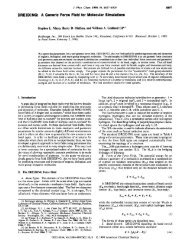
Figure 4.4 Excess Temperature Distribution for the Case <strong>of</strong> 4 Towers in<br />
Linear Array and 90° to Wind Direction
12<br />
2<br />
o<br />
-40-<br />
Exes LIQM ij TWRS 1 ARRAY 135 DEG TO WIND<br />
2 4 6<br />
x/o<br />
8 10 12<br />
Figure 4.9 Excess Liquid Phase Moisture Distribution for the Case <strong>of</strong> 4<br />
Towers in Linear Array and 135 0<br />
to Wind Direction
-41-<br />
Exes TEMP 5 TWRS IN ROUND ARRAY<br />
4 6<br />
X/O<br />
8 10 12<br />
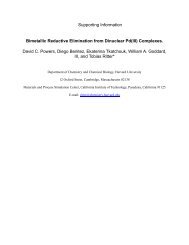
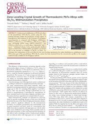
Figure 4.10 Excess Temperature Distribution for the Case <strong>of</strong> 5 Towers<br />
in Round Array
4<br />
2<br />
o<br />
o<br />
-42-<br />
Exes HUMI 5 TWRS IN ROUND ARRAY<br />
2 4 6<br />
x/o<br />
8 10 12<br />
Figure 4.11 Excess Humidity Distribution for the Case <strong>of</strong> 5 Towers in Round<br />
Array
-49-<br />
Three ambient relative humidity pr<strong>of</strong>iles (100%, 70%, 0%) associated with<br />
the relative temperature pr<strong>of</strong>iles were generated and tested. The exit<br />
plume humidities were assumed 100% (saturated) except for one dry plume<br />
case which is 0% for ambient and exit humidities. The input data cards<br />
are presented in Tables 4.4 and 4.5. The predicted results and the compari<br />
sons are shown in Figures 4.17 and 4.18. From the variations <strong>of</strong> plume<br />
trajectory for different ambient humidity conditions, the effect <strong>of</strong> the<br />
ambient humidity can be seen to be quite significant. Similar conclusions<br />
could be drawn for the effect <strong>of</strong> ambient temperature and wind velocity.<br />
The present model overpredicts the plume trajectories for TVA's cases.<br />
This could be due to the incomplete information <strong>of</strong> the ambient conditions<br />
and the neglect <strong>of</strong> drift in the tower initial conditions. Adequate<br />
ambient and source conditions are mandatory for proper model validation.
-54-<br />
Table 4.3 Input Data Cards for Chan et a1. 's (1974) Experiment<br />
with F = 4, K = 1.02<br />
Case (1) 6 Towers in One Array 90 Degrees to Wind F=4, K=1.02<br />
6 100 21 17 11<br />
0 0 1 2 0 0 1 1 0 0 1<br />
.00000 .00000 .00000 .00000 .00000 .00000<br />
.00000 .06501 .13003 .19504 .26006 .32507<br />
.00000 900.00000<br />
25.00000 25.00000<br />
.00000 .00000<br />
.37621 .37621 .37621 .37621 .37621 .37621 .37621 .37621<br />
.37621 .37621 .37621 .37621<br />
.05690 .38374 30.00000 .00000 .00000<br />
.50000 .50000 1.00000 3.00000<br />
6.31250 5.06250 0 0 0 0<br />
EXCS TEMP 6 TWRS 1 ARRAY 90 DEC TO WIND Z/D X/D A3=0.3536 CD=1.5
-57-<br />
CHAPTER 5<br />
CONCLUSIONS AND RECOMMENDATIONS<br />
In this study, a mathematical model and corresponding computer<br />
program have been developed for the prediction <strong>of</strong> plume behavior from<br />
multiple cooling towers. Some comparisons between the predictions<br />
based on the present model and the measured results from laboratories<br />
and the field are made in order to test the model. The following<br />
conclusions and recommendations are made based on this study.<br />
(1) The model is developed for arbitrary vertical pr<strong>of</strong>iles <strong>of</strong><br />
ambient temperature, humidity, wind velocity, and arbitrary tower<br />
arrangement. The velocity defect for the downstream towers due to the<br />
effect <strong>of</strong> the upstream towers and plumes can be included by specifying<br />
different ambient velocity pr<strong>of</strong>iles for each plume. A general expression<br />
for the velocity defect <strong>of</strong> the downstream towers might be developed in<br />
the future.<br />
(2) The temperature range for which this model is valid is -50°C<br />
to 140°C, because <strong>of</strong> the accuracy associated with the calculation <strong>of</strong><br />
the saturation humidity.<br />
(3) A set <strong>of</strong> suggested values <strong>of</strong> entrainment and drag coefficients<br />
have been incorporated in the computer program. Because <strong>of</strong> the rapid<br />
merging and usually rapid bending over <strong>of</strong> the plumes, the coefficients<br />
a 3 , as and Cd are the most important ones. Better estimates <strong>of</strong> their<br />
values are needed such as by further experimental study or field program.<br />
(4) The merging criteria and processes (defined in this model by<br />
equations (2.38) (2.39) and (2.40),) could also be improved when further
-58-<br />
research results on plume interaction are available.<br />
(5) The blockage and recirculation effects in the wake zone <strong>of</strong> the<br />
towers and plumes have not been incorporated in the present model.<br />
Future effort could be made to include these effects.<br />
(6) Based on comparisons between model and laboratory results<br />
(Fan, and Chan et al.), good predictions <strong>of</strong> dry plume behavior can be<br />
obtained. In order to verify the model for actual cooling tower plumes,<br />
a more complete set <strong>of</strong> experimental dataancluding the plume width,<br />
trajectory, dilution and detailed ambient pr<strong>of</strong>iles <strong>of</strong> temperature,<br />
humidity and wind velocity) are required. Therefore, a complete set <strong>of</strong><br />
field measurement are strongly recommended for validation <strong>of</strong> the model.
-59-<br />
REFERENCES<br />
Abraham, G. (1970), "The Flow <strong>of</strong> Round Buoyant Jets Issuing Vertically<br />
into Ambient Fluid Flowing in a Horizontal Direction," Advan. Water<br />
Poll. Res. Proc. Int. Conf. Water Poll. Res. 5th Paper 111-15.<br />
Briggs, G. A. (1969), "Plume Rise," AEC Critical Review Series Report.<br />
Report number TID-25075.<br />
Briggs, G. A. (1974), "Plume Rise<br />
Environment-74. CONF-74032,<br />
Technical Exchange Service.<br />
pp. 161-179.<br />
from Multiple Sources,!!<br />
ERDA Symposium Series.<br />
U.S. Dept. <strong>of</strong> Commerce,<br />
Cooling Tower<br />
National<br />
Springhill, VA.,<br />
Carpenter, S. R., F. W. Thomas, and R. E. Gartrell (1968), "Full-Scale<br />
Study <strong>of</strong> Plume Rise at Large Electric Generating Stations," TVA,<br />
Muscle Shoals. Alabama.<br />
Chan, T. L., S.-T. Hsu, J.-T. Lin, K.-H. Hsu, N.-S. Huang, S. C. Jain, C. E.<br />
Tsai, T. E. Croley II, H. Fordyce and J. F. Kennedy, "Plume Recirculation<br />
and In terf erence in Mechanical Draf t Cooling Towers," Iowa Ins t. Hyd. Res.<br />
Rep. No. 160, 41 pp.<br />
Csanady, G. T. (1971), "Bent-Over Vapor Plume," J. Appl. Meteor., 10,<br />
34-42.<br />
Davis, L. R. (1975), "Analysis <strong>of</strong> Multiple Cell Mechanical Draft Cooling<br />
Towers," Environ. Prot. Agency Rep. Office <strong>of</strong> Research and Development,<br />
Ecological Research Series, EPA-660l3-75-039.<br />
Fan, L. N. (1967), "Turbulent Buoyant Jets into Stratified or Flowing<br />
Ambient Fluid," <strong>California</strong> <strong>Institute</strong> <strong>of</strong> <strong>Technology</strong>, W. M. Keck<br />
Laboratory <strong>of</strong> Hydraulics and Water Resources, Rep. No. KH-R-15.<br />
Fox, D. G. (1970), "Forced Plume in a Stratified Fluid," J. Geophys.<br />
Res., 75 (33), 6818-35.<br />
Hanna, S. R. (1972), "Rise and Condensation <strong>of</strong> Large Cooling Tower Plumes,"<br />
J. Appl. Meteor., 11, 793-799.<br />
Hirst, E. A. (1971), "Analysis <strong>of</strong> Round, Turbulent, Buoyant Jets Discharged<br />
to Flowing Stratified Ambients," Oak Ridge National<br />
Laboratory, Report Number ORNL-4685.<br />
Hoult, D. P., J. A. Fay, and L. J. Forney (1969), "A Theory <strong>of</strong> Plume<br />
Rise Compared with Field Observations," J. Air Pollut. Contr.<br />
Assoc. 19(9), 585-90.<br />
Jirka, G. and D.R.F.<br />
port Diffusers<br />
M. Parsons Lab.<br />
Harleman (1974), "The Mechanics <strong>of</strong> Submerged Multifor<br />
Buoyant Discharges in Shallow Water," MIT Ralph<br />
for Water Resources and Hydraulics, Report Number 169.
-60-<br />
Koh, R.C.Y. and N. H. Brooks (1975), "Fluid Mechanics <strong>of</strong> Waste-Water<br />
Disposal in the Ocean," Ann. Rev. Fluid Mech., 7:187-211.<br />
Koh, R.C.Y. and Y. C. Chang (1973), "Mathematical Model for Barged Ocean<br />
Disposal <strong>of</strong> Wastes," Environ. Pro t. Agency, Office <strong>of</strong> Research and<br />
Development, Environ. Prot. Tech. Series, EPA-660/2-73-029.<br />
Koh, R.C.Y. and L. N. Fan (1970), "Mathematical Models for the Prediction<br />
<strong>of</strong> Temperature Distributions Resulting from the Discharge <strong>of</strong><br />
Heated Water into Large Bodies <strong>of</strong> Water," Environ. Prot. Agency<br />
Rep. 16130 DWO 10/70,219 pp. (Also Tetra Tech, Inc., Rep. TC-170).<br />
Linsley, Jr., R. K., M. A. Kohler, and J.L.H. Paulhus (1975), Hydrology for<br />
Engineers, McGraw-Hill Book Company, Inc., New York, NY.<br />
List, E. J. and J. Imberger (1973), "Turbulent Entrainment in Buoyant<br />
Jets and Plumes," J. Hydrau1. Div., Proc. ASCE, 99:1461-74.<br />
Meyer, J. H., T. W. Eagles, L. C. Kohlenstein, J. A. Kagan, and W. D.<br />
Stanbro (1974), -ItMechanical Draft Cooling Tmver Visible Plume<br />
Behavior: Measurements, Models, Predictions," Cooling Tower<br />
Environment-74. CONF-74032, ERDA Symposium Series. National<br />
Technical Exchange Service, U.S. Dept. <strong>of</strong> Commerce, Springhill, VA,<br />
pp. 307-352.<br />
Morton, B. R. (1957), "Buoyant Plumes in a Moist Atmosphere," J. Fluid<br />
Mech., 2, 127-144.<br />
Morton, B. R., G. I. Taylor and J. S. Turner (1956), "Turbulent Gravitational<br />
Convection from Maintained and Instanteous Sources," Proc.<br />
Roy. Soc. London, Ser. A 234:1-23.<br />
Richards, J. M. (1963), "Experiments on the Motion <strong>of</strong> Isolated Cylindrical<br />
Thermals through Unstratified Surroundings," Intern. J. <strong>of</strong><br />
Air and Water Pollut., 7, pp. 17-34.<br />
Richards, J. M. (1971), "Simple Expression for the Saturation Vapor<br />
Pressure <strong>of</strong> Water in the Range -50° to 140°C," Brit. J. App1. Phys.,<br />
4, 115-118.<br />
Schatzmann, M. (1977), "A Mathematical Model for the Prediction <strong>of</strong> Plume<br />
Rise in Stratified Flows," Sonderforschungsbereich 80, University<br />
<strong>of</strong> Karlsruhe, W. Germany.<br />
Slawson, P. R. and G. T. Csanady (1967), "On the Mean Path <strong>of</strong> Buoyant,<br />
Bent-Over Chimney Plumes," J. Fluid Mech., 28, 311-322.<br />
Slawson, P. R. and G. T. Csanady (1971), "The Effect <strong>of</strong> Atmospheric<br />
Conditions on Plume Rise," J. Fluid Mech., 47, 33-39.
-61-<br />
Slawson, P. R., J. H. Coleman, and J. W. Frey (1975), "Some Observations<br />
on Cooling-Tower Plume Behavior at the Paradise Steam Plant,"<br />
Cooling Tower Environment--1974 (ERDA Symp. Series: CONF-740302),<br />
147-160.<br />
Weil, J. C. (1974), "The Rise <strong>of</strong> Moist, Buoyant Plumes," J. Appl. Meteor.,<br />
13, 435-443.<br />
Wigley, T. M. L. (1974), Comments on "A Simple but Accurate Formula for<br />
the Saturation Vapor Pressure over Liquid Water," J. Appl. Meteor.,<br />
13, 60S.<br />
Wigley, T. M. L. (1975), "A Numerical Analysis <strong>of</strong> the Effect <strong>of</strong> Condensation<br />
on Plume Rise," J. Appl. Meteor., 14, 1105-1109.<br />
Wigley, T.M.L. (1975), "Condensation in Jets, Industrial Plumes and Cooling<br />
Tower Plumes, II J. Appl. Meteor., 14, 7S-S6.<br />
Wigley, T.M.L. and P. R. Salwson (1971), "On the Condensation <strong>of</strong> Buoyant,<br />
Moist Bent-Over Plumes," J. Appl. Meteor., 10, 253-259.<br />
Wigley, T. M. 1. and P. R. Salwson (1972), "A Comparison <strong>of</strong> Wet and Dry<br />
Bent-Over Plumes," J. Appl. Meteor., 11, 335-340.<br />
Wright, S. J. (1977), "Effects <strong>of</strong> Ambient Crossflows and Density Stratification<br />
<strong>of</strong> the Characteristic Behavior <strong>of</strong> Round, Turbulent Buoyant<br />
Jets," <strong>California</strong> <strong>Institute</strong> <strong>of</strong> <strong>Technology</strong>, W. M. Keck Laboratory <strong>of</strong><br />
Hydraulics and Water Resources, Report No. KH-R-36, 254 pp.
A-I<br />
APPENDIX A<br />
COMPUTER PROGRAM<br />
The computer program based on the model and listed in Appendix C<br />
was tested on an IBM 370/158. The detailed input and output information<br />
are listed in this Appendix. The input ambient wind velocity pr<strong>of</strong>iles<br />
(AU(NP,MG) for each tower are designed to allow consideration <strong>of</strong> the<br />
velocity defect in the wake <strong>of</strong> upstream towers (i.e., the tower array<br />
parallel to the ambient wind direction). In addition, some suggested<br />
input values are listed below for reference:<br />
NS = 300<br />
NX 40<br />
NY = 40<br />
NCONT = 11<br />
IX(3) = IX(6) = IX(ll) =0<br />
In this Appendix, the input sequence as well as the input and output<br />
variables are tabulated, explained and related to the symbols used in the<br />
text <strong>of</strong> this report.
A-2<br />
INPUT SEQUENCE<br />
Symbol Parameter Format Subroutine<br />
NP,NS,NX,NY,NCONT 514 CTPS<br />
(IX(I) ,1=1,11) 11 14 MTP<br />
(CX(I) ,1=1 ,NP) 8Fl0.5 MTP<br />
(CY(I) ,I=l ,NP) 8F10.5 MTP<br />
(AZ( 1),1=1 ,MG) 8Fl0.5 MTP<br />
(AT (I ) , 1=1 , MG ) 8Fl0.5 MTP<br />
(AH( I), 1=1 ,MG) 8Fl0.5 MTP<br />
( (AU (I , J ) ,J = 1 ,MG) , 1=1 , N P ) 8Fl0.5 MTP<br />
01(1) ,UO(1), TO(1) ,HO(1) ,WO(1) IX(l)=O+ 8F10.5 MTP<br />
(OI(I),I=l,NP) IX(l )=1* 8F10.5 MTP<br />
(UO( 1),1=1 ,NP) IX(l )=1* 8F10.5 MTP<br />
(TO(I) ,1=1 ,NP) IX(1)=l* 8F10.5 MTP<br />
(HO(I) ,1=1 ,NP) IX(l )=1* 8F10.5 MTP<br />
(WO ( I ) , 1=1 , N P ) IX(l )=1* 8F10.5 MTP<br />
A1,A2,A3,A4,CO,TURBF IX(2)=1* 8F10.5 MTP<br />
OX,OZ,XO,ZO IX(3)=1* 4F10.5 OUTPUT<br />
WIDTH, HITE,MORE,NOMAP,ICENT<br />
NOTICK<br />
IX(l1)=l* 2F10.5<br />
414<br />
OUTPUT<br />
(HEON(k) ,k=l, 10), (LABY(L) ,L=l ,5) ,(LABX(M) ,M=l ,5) IX(8)=1* 20A4 OUTPUT<br />
(HEON ( k) , k= 1 , 1 0) , (LABY (L) , L = 1 ,5) , (LABX (M) ,M= 1 ,5) IX(9)=1* 20A4 OUTPUT<br />
(HEON ( k) , k= 1 , 1 0) , (LABY (L) , L = 1 ,5) , (LABX (M) ,M= 1 ,5) IX(10)=1* 20A4 OUTPUT<br />
+ Skip card if IX(l)=l<br />
* Skip card if the corresponding IX(I)=O, (1=1,2,3,11,8,9,10)
In Program<br />
NP<br />
NS<br />
NX, NY<br />
[CONTA(NX,NY) ]<br />
NCONT<br />
[CONTB(NCONT)]<br />
IX(l)<br />
IX(2)<br />
IX(3)<br />
IX(4)<br />
IX(5)<br />
IX(6)<br />
IX(7)<br />
IX(8)<br />
IX(9)<br />
IX(lO)<br />
IX(ll)<br />
A-3<br />
EXPLANATION OF THE INPUT SYMBOLS<br />
In Text Remarks<br />
Total number <strong>of</strong> towers<br />
Desired number <strong>of</strong> calculation steps<br />
Horizontal and vertical grid sizes, respectively<br />
(for contour plot)<br />
Desired contour levels for plotting<br />
IX(l)=O<br />
IX(l)=l<br />
rX(2)=O<br />
IX(2)=1<br />
Same exit conditions <strong>of</strong> all the<br />
plumes (Input one card only)<br />
Different exit conditions <strong>of</strong> the<br />
plumes<br />
No input card <strong>of</strong> entrainment and<br />
drag coefficients is needed<br />
Input the desired entrainment and<br />
drag coefficients<br />
IX(3)=O No input card <strong>of</strong> DX, DZ, XO and ZO<br />
is needed<br />
IX(3)=l Input the desired values <strong>of</strong> DX, DZ,<br />
XO and ZO<br />
IX(3)=-1 No plot needed<br />
MG<br />
INRPR<br />
IPNT=O<br />
Number <strong>of</strong> vertical levels for<br />
ambient conditions<br />
Interval <strong>of</strong> detailed printout for<br />
plume 1<br />
For contour plot (always use IPNT=O)<br />
LC=O For cluster array (round array) <strong>of</strong><br />
towers<br />
LC=l For line or random array <strong>of</strong> towers<br />
IX(8)=O<br />
IX(8)=1<br />
No contour map plotted for plume<br />
excess temperature<br />
Contour map plotted for plume<br />
excess temperature<br />
IX(9)=O No contour map plotted for plume<br />
excess humidity<br />
IX(9)=1 Contour map plotted for plume excess<br />
humidity<br />
IX(lO)=O No contour map plotted for plume<br />
excess liquid moisture<br />
IX(lO)=l Contour map plotted for plume excess<br />
liquid moisture<br />
IX(ll)=O No input card <strong>of</strong> W1DTH, HITE, MORE,<br />
NOMAP, ICENT, and NOTICK is needed<br />
IX(ll)=l Input the desired values <strong>of</strong> WIDTH,<br />
HITE, MORE, NOMAP, ICENT and NOTICK
In PrograIll<br />
CX(NP)<br />
CY(NP)<br />
AZ(MG)<br />
AT (MG)<br />
AH(MG)<br />
AU(NP ,MG)<br />
DI(NP)<br />
UO(NP)<br />
TO(NP)<br />
HO(NP)<br />
WO(NP)<br />
Al,A2,A3<br />
and A4<br />
CD<br />
TURBF<br />
DX,DZ<br />
XO,ZO<br />
WIDTH,HITE<br />
MORE<br />
NOMAP<br />
ICENT<br />
NOTICK<br />
In Text<br />
x<br />
y<br />
z<br />
ta<br />
U a<br />
D o<br />
U o<br />
A-4<br />
Remarks<br />
x-coordinates <strong>of</strong> towers (in m)<br />
y-coordinates <strong>of</strong> towers (in m)<br />
Ambient levels (in m)<br />
Ambient temperature pr<strong>of</strong>ile corresponding to<br />
AZeI) (in °C)<br />
Ambient relative humidty pr<strong>of</strong>ile corresponding<br />
to AZ(I) (in percentage <strong>of</strong> the saturation<br />
humidity)<br />
Ambient wind velocity pr<strong>of</strong>ile corresponding<br />
to AZ(I) for each tower (in m/sec)<br />
Diameter <strong>of</strong> each tower (in m)<br />
Exit velocity <strong>of</strong> each plume (in m/sec)<br />
Exit temperature <strong>of</strong> each plume (in °C)<br />
Exit specific humidity <strong>of</strong> each plume (in<br />
kg/kg)<br />
Exit liquid phase moisture <strong>of</strong> each plume<br />
(in kg/kg)<br />
Entrainment coefficients (Default: Al=O.0806,<br />
A2=O.4775, A3=O.3536, A4=O.)<br />
Drag coefficient (Default: CD=1.5)<br />
Intensity <strong>of</strong> ambient turbulent fluctuations<br />
(in percentage, decimal; Default: TURBF=8.)<br />
Increments <strong>of</strong> grid size in x and z directions,<br />
respectively (Normalized by the diameter <strong>of</strong><br />
the first tower; Default:DX=O.5, DZ=O.5)<br />
Location <strong>of</strong> the center <strong>of</strong> the top <strong>of</strong> the<br />
first tower in the grid (Normalized by the<br />
diameter <strong>of</strong> the first tower; Default:XO=l,<br />
Z0=2. )<br />
Width and height <strong>of</strong> contour map, respectively<br />
(Inches; Default: 8", 8")<br />
MORE=l Do not finish <strong>of</strong>f the map (Default:<br />
MORE=O)<br />
NOMAP=l Do not force grid to be -square<br />
(Default:NOMAP=O)<br />
ICENT=l Do not center the title (Default:<br />
ICENT=O)<br />
NOCITK=l Do not draw tick marks (Default:<br />
NOTICK=O)
In Program<br />
HEDN(lO)<br />
LABY(5)<br />
LABX(5)<br />
In Text<br />
A-5<br />
Remarks<br />
40 characters to plot as<br />
(Default: Blank)<br />
20 characters to plot as<br />
left (Default: Blank)<br />
20 characters to plot as<br />
bottom (Default: Blank)<br />
title on top<br />
label on vertical<br />
label on horizontal
In Program<br />
PX(NP,NS)<br />
PY(NP,NS)<br />
PZ(NP,NS)<br />
PS(NP,NS)<br />
PCOS(NP,NS)<br />
PSIN(NP,NS)<br />
PQ(NP,NS)<br />
PMX(NP,NS)<br />
PMZ(NP,NS)<br />
PF(NP,NS)<br />
PG(NP,NS)<br />
PH(NP,NS)<br />
PW(NP,NS)<br />
PT(NP,NS)<br />
PET(NP,NS)<br />
PEH(NP,NS)<br />
PAN:(NP,NS)<br />
PU(NP,NS)<br />
PENT(NP,NS)<br />
PA(NP,NS)<br />
PB(NP,NS)<br />
PC(NP,NS)<br />
PDIL(NP,NS)<br />
CONTA(NX,NY)<br />
CONTB(NCONT)<br />
IND (I)<br />
IS (I)<br />
MP(I)<br />
MS(I)<br />
A(I)<br />
Bl (I)<br />
B2(I)<br />
BXZ(I)<br />
BY(I)<br />
PMCOS (I)<br />
PMSIN(I)<br />
DW(I)<br />
NEV(I)<br />
NEV(I)<br />
PAl<br />
GRA<br />
Al<br />
A2<br />
A3<br />
A4<br />
B-1<br />
APPENDIX B<br />
EXPLANATION OF THE IMPORTANT SYMBOLS IN THE PROGRAM MTP<br />
In Text<br />
x<br />
y<br />
z<br />
s<br />
case<br />
sine<br />
Q<br />
:x<br />
F Z<br />
G<br />
H<br />
W<br />
T<br />
tp - ta<br />
qp - qa<br />
e<br />
U<br />
E<br />
A<br />
b or (Bl+B2)/2<br />
BXZ<br />
Q/Qo<br />
A<br />
Bl<br />
B2<br />
BXZ<br />
BY<br />
cos<br />
sin<br />
2·BY<br />
IND(I)=5<br />
IND(I)=l<br />
IND(I)=2<br />
IND(I)=3<br />
Remarks<br />
*<br />
Excess temperature<br />
Excess humidity<br />
*<br />
Net plume velocity<br />
*<br />
Average plume width<br />
*<br />
Plume dilution<br />
Normalized PET,PEH & PW (or PEW)<br />
Contour levels<br />
Indication <strong>of</strong> the status <strong>of</strong> each plume<br />
Plume which has not been started<br />
Single plume<br />
Merged plume<br />
All plumes are merged<br />
Beginning step number for each plume<br />
Merged plume pair<br />
Merged plume step numbers associated<br />
with MP(I)<br />
*<br />
Beginning step number for visible plume<br />
Ending step number for visible plume<br />
3.1415926<br />
*
In Program In Text<br />
CD<br />
TURBF<br />
UC<br />
B<br />
Cd<br />
U' a<br />
Up<br />
TP<br />
HP<br />
WP<br />
ET<br />
EH<br />
MG<br />
tp<br />
qp<br />
O"p<br />
tp - ta<br />
qp - qa<br />
CFRL<br />
ALV<br />
CPA<br />
ANG<br />
ITHP<br />
FrLC<br />
Lv<br />
Cpa<br />
e<br />
ENTRAN<br />
IQ<br />
E<br />
IL<br />
IK<br />
KE(I)<br />
Y(I) Y(I)=Q<br />
Y(2)=Mcose<br />
Y(3)=Msine<br />
Y(4)=G<br />
Y(5)=F<br />
Y(6)=x<br />
Y(7)=z<br />
YP(I)<br />
YRI(I),YR2(I),<br />
& YS (I)<br />
YRIP(I),YR2P(I) ,<br />
& YSP(I)<br />
* Refer to "List <strong>of</strong> Symbols"<br />
3<br />
B-2<br />
Remarks<br />
*<br />
Plume width<br />
*<br />
Excess temperature<br />
Excess humidity<br />
Elevation level<br />
* ith plume<br />
* All the plumes have not been<br />
completely merged<br />
All the plumes have merged<br />
All the plumes have merged and<br />
become a round plume again<br />
Number <strong>of</strong> merged pairs<br />
Plume step number<br />
Ending step number <strong>of</strong> each plume<br />
*<br />
Derivatives <strong>of</strong> Y(I) with respect to s<br />
Y(I) associated with the two half<br />
round plumes and the central slot<br />
plume for the merged plume<br />
YP(I) associated with the two half<br />
round plumes and the central slot<br />
plume for the merged plume
C-l<br />
APPENDIX C<br />
LISTING OF PROGRAM
C-10<br />
fORTRAN IV G LEVEL 20.7 VS BLANK DATE 6/07/77 14:<br />
0096 END<br />
----- - ------<br />
.------------------ -_.-- ----- - ._--
C-43<br />
FORTRAN IV G lEVEL 20.1 VS CONTU<br />
0112<br />
0113<br />
0114<br />
0115<br />
YBIG=YOFF+(A(I.IJ-YMIN1*YD<br />
9S CALL SYSPLT(XBIG.YBIG.2)<br />
RETURN<br />
END<br />
DATE = 8/03111 10: 14:
C-47<br />
FORTRAN IV G LEVEL 20.1 VS TOPO<br />
0112<br />
0113<br />
0114<br />
0115<br />
0116<br />
0111<br />
0118<br />
0119<br />
0120<br />
0121<br />
0122<br />
0123<br />
0124<br />
0125<br />
0126<br />
0121<br />
0128<br />
0129<br />
0130<br />
0131<br />
0132<br />
0133<br />
10116 IF(ABS lXPA-XPBJ-.001J5003,5004,5004<br />
5003 IFlABS lYPA-YPB)-.001110C,5004,5004<br />
5004 CALL PlOTllXPA,YPA,XPB,YPBI<br />
100 RCzCNTRlNC+1J<br />
NC=NC+l<br />
GO TO 80<br />
103 XPA : XCl<br />
YPA & YCl<br />
GO TO 99<br />
106 Q:(RC-RM)/(RL-RMI<br />
XPA=XCM-Q*(XCM-XCLJ<br />
YPA=YCM-Q* (YCM-YCL)<br />
GO TO 99<br />
110 GO TO l,1112,1181<br />
112 ASSIGN 118 TO l<br />
FIR =RBIJ-1 J<br />
XX aX I J-lI<br />
YY =Y (10<br />
GO TO 31<br />
118 CONTINUE<br />
RETURN<br />
END<br />
DATE 8/03/77 10:14