Operating Instructions CQ Series - Meyer Sound Laboratories Inc.
Operating Instructions CQ Series - Meyer Sound Laboratories Inc.
Operating Instructions CQ Series - Meyer Sound Laboratories Inc.

You also want an ePaper? Increase the reach of your titles
YUMPU automatically turns print PDFs into web optimized ePapers that Google loves.
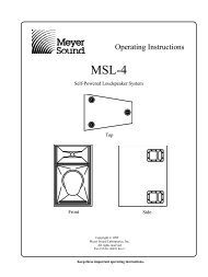
LD-1A with <strong>CQ</strong> and 650-P<br />
Activating the Lo Cut filter on the LD-1A for the Mid-Hi<br />
output also eliminates the low frequency rise caused<br />
by the overlap between the <strong>CQ</strong> and 650-P. Although a<br />
typical <strong>CQ</strong> : 650-P ratio is 2:1, separate Sub and Mid-Hi<br />
level controls on the LD-1A allow the ratio to vary<br />
while maintaining control of the spectral balance of<br />
the system.<br />
Mid-hi<br />
LD-1A<br />
Line Driver<br />
Sub<br />
<strong>CQ</strong>-1 or<br />
<strong>CQ</strong>-2<br />
650-P<br />
Set the <strong>CQ</strong> and 650-P to the same polarity.<br />
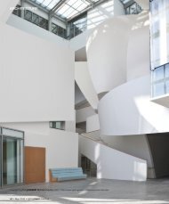
LD-1A with Flown MSL-4, DS-2P, and <strong>CQ</strong>;<br />
650-P on the Floor<br />
This example shows the LD-1A integrating a complete<br />
system of speakers appropriate for a large venue.<br />
Although channels 1, 3, and 5 constitute half of a<br />
complete system, channels 2, 4, and 6 can be used<br />
with identical connections to create the other half of<br />
the system. The MSL-4 mid-hi, DS-2P mid-bass, and<br />
<strong>CQ</strong> down-fill speakers are flown; the 650-P subwoofers<br />
are on the floor.<br />
The Mid-Hi and CH 3 outputs drive the inner three<br />
and outer two speakers, respectively, of the MSL-4<br />
array. These two outputs apply appropriate levels for<br />
speakers directed at audience locations at different<br />
distances from the main system. The diagram shows the<br />
additional mid-hi output created by connecting the<br />
CH 1 Loop to the CH 3 input. Using a Y-connection at<br />
the CH 1 input, as shown for the down-fills, accomplishes<br />
the same signal routing.<br />
The Lo Cut and Array EQ switches for the Mid-Hi and<br />
CH 3 outputs should be in. The Lo Cut filter eliminates<br />
the rise caused by the overlap between the MSL-4 and<br />
DS-2P/650-P systems. The Array EQ filter minimizes<br />
the low-mid rise caused by the MSL-4 array.<br />
The DS-2 and Sub outputs drive the DS-2P and 650-P<br />
systems with the DS-2 & Crossover switch in. Set the<br />
MSL-4 and DS-2P to the same polarity. The polarity of<br />
the 650-P depends on the displacement from the flown<br />
system.<br />
CH 5 controls the <strong>CQ</strong> down-fill system. Since the main<br />
system is normally set to a higher volume than the<br />
down-fill system to project farther into the venue, the<br />
main system is audible in the down-fill’s coverage<br />
area. To insure that the speakers combine properly in<br />
the overlapping coverage area:<br />
• Set the <strong>CQ</strong> to the opposite polarity to the MSL-4<br />
and DS-2P to phase align the mid-hi frequencies and<br />
minimize the MSL-4’s low frequency down-lobe.<br />
• Use the CH 5 Lo Cut filter to eliminate the low<br />
frequency rise caused by the overlap with the<br />
650-P/DS-2P systems.<br />
• Delay the down-fill to compensate for the<br />
propagation delay between the down-fill and<br />
main systems in the intersecting coverage area.<br />
(This is highly recommended, but not required.)<br />
We recommend using the <strong>Meyer</strong> SIM System II <strong>Sound</strong><br />
Analyzer and CP-10 Parametric Equalizer to optimize this<br />
configuration.<br />
Delay<br />
CP-10 EQ<br />
CP-10 EQ<br />
LD-1A<br />
CH 1<br />
Input Mid-Hi<br />
Output<br />
Loop DS-2<br />
Output<br />
Sub<br />
Output<br />
Input Output<br />
CH 3<br />
Input Output<br />
CH 5<br />
MSL-4 Mid-Hi<br />
DS-2P Mid-Bass<br />
<strong>CQ</strong> Down-fills<br />
650-P Subwoofers<br />
Set the MSL-4 and DS-2P to the same polarity; reverse<br />
the polarity for the <strong>CQ</strong>. The polarity for the 650-P depends<br />
on the displacement from the flown system.<br />
9