

GM HEI TimingComputerInstructionManual - RABID GATOR ...
GM HEI TimingComputerInstructionManual - RABID GATOR ...
GM HEI TimingComputerInstructionManual - RABID GATOR ...

You also want an ePaper? Increase the reach of your titles
YUMPU automatically turns print PDFs into web optimized ePapers that Google loves.
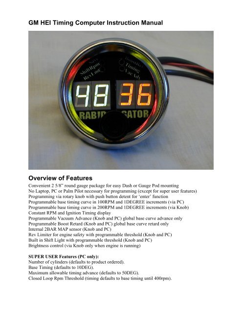
<strong>GM</strong> <strong>HEI</strong> Timing Computer Instruction Manual<br />
Overview of Features<br />
Convenient 2 5/8” round gauge package for easy Dash or Gauge Pod mounting<br />
No Laptop, PC or Palm Pilot necessary for programming (except for super user features)<br />
Programming via rotary knob with push button detent for ‘enter’ function<br />
Programmable base timing curve in 100RPM and 1DEGREE increments (via PC)<br />
Programmable base timing curve in 200RPM and 1DEGREE increments (via Knob)<br />
Constant RPM and Ignition Timing display<br />
Programmable Vacuum Advance (Knob and PC) global base curve advance only<br />
Programmable Boost Retard (Knob and PC) global base curve retard only<br />
Internal 2BAR MAP sensor (Knob and PC)<br />
Rev Limiter for engine safety with programmable threshold (Knob and PC)<br />
Built in Shift Light with programmable threshold (Knob and PC)<br />
Brightness control (via Knob only when engine is running)<br />
SUPER USER Features (PC only):<br />
Number of cylinders (defaults to product ordered).<br />
Base Timing (defaults to 10DEG).<br />
Maximum allowable timing advance (defaults to 50DEG).<br />
Closed Loop Rpm Threshold (timing defaults to base timing until 400rpm).
Mounting<br />
For best results mount in a visible location. Use standard gauge mounting methods (in your<br />
dashboard, or a gauge pod, or a gauge bracket) inside the passenger compartment. Although the<br />
Timing Computer is treated to be weather resistant it CANNOT tolerate under-hood or on-hood<br />
environments.<br />
If you must bend the wires that come out of the back please observe the following guidelines.
Connect the MAP sensor port shown in the photo below
Vehicle already equipped with 7 Pin (Large Diameter Cap)<br />
Wiring<br />
Disconnect the Negative Battery Terminal.<br />
Connect the power wire to a 12v source that is fused and switched.<br />
Drill a ½” hole in the firewall.<br />
Feed the grey cable through the hole.<br />
Feed the vacuum hose through the hole.<br />
Install the pins into the weather-pack connector, wired as follows A=EST B=Reference<br />
C=Bypass D=Ground see photo below<br />
Plug the weather-pack connector into the distributor’s weather-pack connector.<br />
Reconnect the Negative Battery Terminal
Power Up<br />
Turn on your ignition without cranking the engine.<br />
The display should read 5 then 4 then 3 then 2 then 1<br />
Then the display will go blank until you start programming or start cranking<br />
Programming<br />
See the ‘Programming via Knob’ or ‘Programming via Serial Port’ sections.<br />
Prepare to Start your Engine!<br />
Note to simplify the next steps you may want to program a flat timing curve then disconnect and<br />
plug the map sensor hose.<br />
Connect a timing light to the engine and battery<br />
Start your engine. If the engine doesn’t start verify the wiring.<br />
Verify that the timing you see on the Timing Computer matches the timing light<br />
If it doesn’t match then your base timing is probably wrong. It should be corrected by either;<br />
rotating the distributor or changing the ‘Base Timing’ super user setting. Note you can unplug<br />
the Timing Computer from the distributor and run the engine, then use the timing light to note<br />
the timing at idle. This timing should match the base timing setting (usually 10 degrees).
Vehicle NOT equipped with 7 Pin (Large Diameter Cap)<br />
Distributor Installation<br />
Locate a new or used (in good condition) large diameter <strong>HEI</strong> distributor with cap, coil and<br />
module. IT MUST BE A 7 PIN MODULE WITH THE ADDITIONAL WEATHER PACK<br />
CONNECTOR HANGING OUT OF IT AND NO VACUUM ADVANCE CANISTER. The<br />
older 4 pin module with a vacuum advance canister, weights and springs, will NOT work. NOTE<br />
some <strong>GM</strong>C trucks came with the 7 pin module AND a vacuum canister. No testing has been<br />
done at this time.<br />
With the engine off rotate the crankshaft and set Cylinder One to 10 degrees before top dead<br />
center.<br />
Install the distributor and align the magnetic pickup (you can feel a slight detent)<br />
Whichever post the rotor is pointing should get spark plug wire for cylinder 1<br />
The remaining firing order should be wired clockwise around the distributor cap<br />
Wire Switched +12volt power to the BAT terminal<br />
Follow the instructions listed in the previous section.
8pin <strong>GM</strong> <strong>HEI</strong> Timing Computer Instructions<br />
.<br />
Wiring<br />
Disconnect the Negative Battery Terminal.<br />
Connect the power wire to a 12v source that is fused and switched.<br />
Drill a 1” hole in the firewall.<br />
Feed the metri-pack connector and cable through the hole.<br />
Feed the vacuum hose through the hole.<br />
Plug the metri -pack connector into the distributor’s metri -pack connector.<br />
Reconnect the Negative Battery Terminal<br />
Power Up<br />
Turn on your ignition without cranking the engine.<br />
The display should read 5 then 4 then 3 then 2 then 1<br />
Then the display will go blank until you start programming or start cranking<br />
Programming<br />
See the ‘Programming Via Knob’ or ‘Programming Via Serial Port’ sections.<br />
Prepare to Start your Engine!<br />
Note to simplify the next steps you may want to program a flat timing curve then disconnect and<br />
plug the map sensor hose.<br />
Connect a timing light to the engine and battery<br />
Start your engine. If the engine doesn’t start verify the wiring.<br />
Verify that the timing you see on the Timing Computer matches the timing light<br />
If it doesn’t match then your base timing is probably wrong. It should be corrected by either;<br />
rotating the distributor or changing the ‘Base Timing’ super user setting. Note you can unplug<br />
the Timing Computer from the distributor and run the engine, then use the timing light to note<br />
the timing at idle. This timing should match the base timing setting (usually 10 degrees).
Vehicle NOT equipped with 8 Pin (Small Diameter Cap)<br />
Distributor Installation<br />
Locate a new or used (in good condition) small diameter <strong>HEI</strong> distributor with cap, coil and<br />
module. IT MUST BE AN 8 PIN MODULE WITH THE TWO METRI PACK CONNECTORS<br />
PROTRUDING OUT OF THE SIDE AND NO VACUUM ADVANCE CANISTER. If it is not<br />
like this, it will NOT work.<br />
With the engine off rotate the crankshaft and set Cylinder One to 10 degrees before top dead<br />
center.<br />
Install the distributor and align the magnetic pickup (you can feel a slight detent)<br />
Whichever post the rotor is pointing should get spark plug wire for cylinder 1<br />
The remaining firing order should be wired clockwise around the distributor cap<br />
Wire the module as shown in the picture above<br />
Follow the instructions listed in the previous section.
Feature Descriptions<br />
TIMING: the base timing curve for your engine, programmable in 100 rpm (200 via knob) and<br />
1 degree increments. This timing is your Wide Open Throttle (WOT) timing with no vacuum<br />
advance or boost retard factored in. WARNING if you skip over an rpm range the timing for that<br />
range cannot be guaranteed and can ruin your engine.<br />
VACUUM ADVANCE: For normal part throttle driving you can gain fuel economy and throttle<br />
response by advancing the timing based on manifold vacuum. It is a simplified algorithm that<br />
advances the entire base curve by a percentage of your programmed amount. For example if you<br />
program 10 degrees of vacuum advance, then at ‘full’ vacuum (throttle closed) your base curve<br />
will be advanced by 10 degrees. At partial throttle your base curve will be advanced a portion of<br />
the 10 degrees. NOTE some engines especially ones with big cams and rough idle will never<br />
achieve ‘full’ vacuum.<br />
BOOST RETARD: If your engine is turbocharged or supercharged you can retard the timing<br />
based on boost. It is a simplified algorithm that retards the entire base curve by a percentage of<br />
your programmed amount. For example if you program 10 degrees of boost retard, then at 2bar<br />
your base curve will be retarded by 10 degrees. At 1.5bar then your base curve will be retarded<br />
by 5 degrees.<br />
REV LIMIT: To protect your engine set the rev limit to the maximum RPM that you want the<br />
engine to turn. Once this RPM is exceeded then sparks are sequentially cut. NOTE if you<br />
downshift to the wrong gear, no rev limiter is going to protect the engine.
SHIFT LIGHT: If you like to hold gears right up to redline but do not like to lose speed by<br />
bouncing off the rev limiter set the shift light RPM slightly below the rev limit. When the shift<br />
light RPM is exceeded ALL of the feature LEDs come on to warn you to shift! (shown below)<br />
SAVE: To have the desired settings available upon every power-up you can permanently save<br />
your settings to EEPROM.<br />
Feature Utilization<br />
Programming via knob<br />
Programming can only be done while the engine is not running.<br />
Power up the Timing computer.<br />
To select a feature gently press on knob and rotate<br />
The LED will light up the feature you want to modify<br />
When you have selected the feature let go of the knob.<br />
Rotate the knob to change the value of the feature.<br />
Move onto the next feature by again, gently pressing on knob and rotating<br />
For Timing Map editing briefly press the knob in to toggle between RPM and Timing<br />
The highlighted parameter is the one that will change when the knob is rotated<br />
To Save your new settings permanently select SAVE and press the knob for 5 seconds<br />
Once saved, the display will flash random segments and turn off.<br />
If you do not SAVE then your settings will be lost if you cycle power.<br />
Programming via Serial Port<br />
For easier control and quicker programming you may want to use a PC
Download the Programming software from www.RabidGator.com .<br />
Run the software. You should get a screen like seen in Appendix C.<br />
Connect the Timing Computer serial port to the PC’s Comm1<br />
Note PC communication is not functional above idle (closed loop RPM)<br />
Press the read button to get the present settings<br />
Edit the settings according to your preference (Danger: you can damage your engine)<br />
All RPMs are in hundreds (for example 55 = 5500RPM)<br />
All timings are in degrees before top dead center (10 = 10 o BTDC)<br />
All Map Sensor settings are in 8bit ADC counts ( 1BAR approx = 128)<br />
Once editing is completed press the Write button (this is not permanent)<br />
To permanently save the new settings press Save<br />
SUPER USER Features (PC only):<br />
Max RPM: 99 stands for 9900. Please do not change this. It hard limits all engine calculations.<br />
Operation above this or especially above 10000rpm will yield very erratic results<br />
Dwell: Percentage of off time versus on time for coil energy build up. Even though the <strong>HEI</strong><br />
module limits to 6amps you can still ruin your coil by changing this.<br />
Base Timing: Like <strong>GM</strong> the base timing should be 10 degrees. Changing this is a simple way to<br />
advance or retard the whole curve but that should not change more than 5 degrees either way<br />
because rotor phasing will be affected. Also note negative values wont work. Also note this<br />
affects limp home mode.<br />
Max Timing: Hard caps the vacuum advance from advancing too far.<br />
cLoopRpm: is the RPM where the timing computer takes over ignition timing. Increasing it is<br />
useful with cams that prohibit low idle RPMs.<br />
maxVac is the 8bit ADC value at which the MAP sensor no longer advances.<br />
minVac is the 8bit ADC value at which the MAP sensor will not start affecting advance mainly<br />
for hysteresis purposes when pegging is not successful.<br />
minBoost is the 8bit ADC value at which the MAP sensor will not start affecting retard, mainly<br />
for hysteresis purposes when pegging is not successful.<br />
vBattHigh is 8bit ADC representation of battery voltage used in hysteresis of compensating<br />
dwell for less energy..<br />
vBattLow is 8bit ADC representation of battery voltage used in hysteresis of compensating dwell<br />
for more energy.<br />
nbOfCyls is used if the timing computer is moved to an engine with more or less cylinders. This<br />
feature is not supported yet and default to the product ordered.<br />
bankSpace is the number of degrees between firings which is useful in odd fire engines but it is<br />
also not supported yet.
Upgrading Firmware via Serial Port (Bootloader)<br />
The Timing Computer has a small kernel of software dedicated to upgrading to future releases in<br />
firmware. This kernel is known as a ‘Bootloader’. To upgrade firmware do the following….<br />
Download the upgrade from www.rabidgator.com<br />
Run your favorite Terminal Emulator on your PC… or Download and install ‘Tera Term Pro’<br />
from http://hp.vector.co.jp/authors/VA002416/teraterm.html Note you can use ‘Hyper Terminal’<br />
(supplied with Windows) but it is much more confusing than Tera Term Pro<br />
.<br />
Run Tera Term Pro and configure the opening screen as follows, with your comport.<br />
and press OK<br />
Connect the PC COMport to the Timing Computer via the serial cable<br />
Ground the Green pigtail hanging out of the serial port connector.<br />
Power down the Timing Computer<br />
Power up the Timing Computer.<br />
The Terminal Emulator will show the following prompt.
Press ‘a’ to ‘Erase Flash’ Five seconds later you will get the prompt back like this:<br />
If you get an error message, cycle power and start over.<br />
If error message persists contact Rabid Gator.<br />
Then Press ‘b’ to ‘Program Flash’ it will prompt you for the file like this
Then select File / Send File… select the .s19 file you downloaded from rabidgator.<br />
While downloading it will look like this<br />
When done it will look like this<br />
You have Successfully downloaded new firmware!<br />
Remove the ground from the pigtail and cycle power.
APPENDIX A: Troubleshooting and Error Codes<br />
If you are experiencing technical difficulty you may simply unplug the Timing Computer from<br />
the distributor. The <strong>HEI</strong> module will default to a limp-home timing curve between 10 and 20<br />
degrees BTDC.<br />
If you see an error code displayed here is the following meaning:<br />
Err1 is an incomplete serial message was received by the serial port and it timed out.<br />
Err 2 is a write/save to the EEPROM timed out.<br />
Err 3 is an error occurred writing to the EEPROM
APPENDIX B: Knob Editing Example photos<br />
Programming the Base Timing Curve via knob<br />
Press the knob in and rotate until the LED is lit. In the photo below notice the 400 RPM is<br />
brighter than the 10 degrees. This means the RPM can be changed and the timing for the<br />
associated RPM will be displayed.<br />
To edit the timing press the knob in briefly (just tap it) and timing will be brighter than RPM and it<br />
will look like the photo below. Now you can change timing.
Programming the Vacuum Advance via knob<br />
Press the knob in and rotate until the LED is lit. Notice the 10 degree timing is bright and<br />
change-able. This means the whole base curve will be advanced by 10 degrees at full vacuum.<br />
The RPM displayed is irrelevant.
Programming the Boost Retard via knob<br />
Press the knob in and rotate until the LED is lit. Notice the 10 degree timing is bright and<br />
change-able. This means the whole base curve will be retarded by 10 degrees at full boost<br />
(2BAR). The RPM displayed is irrelevant.
Programming the Rev-Limiter via knob<br />
Press the knob in and rotate until the LED is lit. Notice the 8700 RPM is bright and change-able.<br />
This means the engine will be rev-limited at 8700 RPM. The timing displayed is irrelevant.
Programming the Shift Light RPM Activation via knob<br />
Press the knob in and rotate until the LED is lit. Notice the 6000 RPM is bright and change-able.<br />
This means the shift light will be activated at 6000 RPM. The timing displayed is irrelevant.
Saving your values via knob<br />
Press the knob in and rotate until the LED is lit. Notice both RPM and Timing are dim. This<br />
means nothing is change-able. If you then hold the knob in for 5 seconds you will permanently<br />
save all your Timing and RPM settings to EEPROM.
APPENDIX C: PC Programming Software<br />
all communications will take place at 38.4k baud, No Parity, 1 Start and Stop bits.<br />
Write = send parameters to RAM, the first step of applying new values.<br />
Save = copy parameters from RAM to EEPROM for permanent use.
APPENDIX D: Legal and Glossary of Terms<br />
<strong>GM</strong> and <strong>HEI</strong> are trademarks of General Motors Corporation<br />
ADC = Analog to Digital Converter, converts real world signals into digital representation.<br />
1BAR = one atmosphere approximately the pressure at sea level<br />
BTDC = piston position Before Top Dead Center<br />
EEPROM = storage memory that will be remembered if power is removed<br />
<strong>HEI</strong> = High Energy Ignition<br />
Hysteresis = the middle point of no change in activity.<br />
LED = Light Emitting Diode, in this case red or green lights.<br />
MAP = Manifold Air Pressure Sensor, an expensive device that converts engine vacuum or boost<br />
to an analog signal.<br />
RAM = memory that will be lost if power is removed.<br />
Rotor Phasing = where the rotor is pointing at the time of spark creation, relative to where the<br />
high voltage wire terminal is located. Optimally the rotor is pointing directly at the terminal but<br />
with EST it is always a compromise.<br />
RPM = revolutions per minute<br />
All the information here in is believed to be true.