Evaluation Environment for AUTOSAR-Autocode in Motor Control ...
Evaluation Environment for AUTOSAR-Autocode in Motor Control ...
Evaluation Environment for AUTOSAR-Autocode in Motor Control ...

Create successful ePaper yourself
Turn your PDF publications into a flip-book with our unique Google optimized e-Paper software.
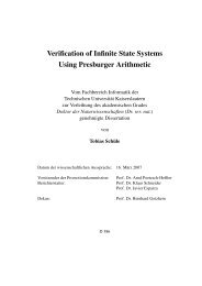
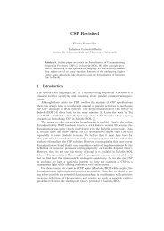
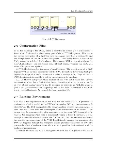
SWC1 SWC2 SWC3<br />
2.6 Configuration Files<br />
. . .<br />
Figure 2.7: VFB diagram<br />
SWCn<br />
Virtual Functional Bus<br />
2.6 Configuration Files<br />
To do the mapp<strong>in</strong>g to the ECUs, which is described <strong>in</strong> section 2.2, it is necessary to<br />
know a lot of <strong>in</strong><strong>for</strong>mation about every part of the <strong>AUTOSAR</strong> system. This means<br />
the precise description of a SWC <strong>for</strong> each mechanism described <strong>in</strong> section 2.4 and<br />
the configuration of the ECUs and the system. This configuration is done <strong>in</strong> an<br />
XML <strong>for</strong>mat <strong>for</strong> a def<strong>in</strong>ed XML scheme. The concrete XML scheme depends on the<br />
<strong>AUTOSAR</strong> release. For one release some different scheme versions can exist, as a<br />
result of bug fixes and updates.<br />
<strong>AUTOSAR</strong> dist<strong>in</strong>guishes two cases of specifications. The specification of a SWC<br />
together with its <strong>in</strong>ternal behavior is called a SWC description. Everyth<strong>in</strong>g that goes<br />
beyond the scope of a s<strong>in</strong>gle component is called a configuration. Together with a<br />
SWC description it is possible to deliver the component to suppliers.<br />
<strong>AUTOSAR</strong> does not specify, which <strong>in</strong><strong>for</strong>mation has to be put <strong>in</strong> which files. Instead<br />
the structure of the files is flexible that the whole configuration can be put <strong>in</strong> one file<br />
or every object can have its own file. To reference an object <strong>in</strong> an XML file a unique<br />
path is used, which consists of the package names that have to traversed <strong>in</strong> the XML<br />
tree to reach this object. An example is given <strong>in</strong> section 2.8.<br />
2.7 Runtime <strong>Environment</strong><br />
The RTE is the implementation of the VFB <strong>for</strong> one specific ECU. It provides the<br />
environment which is needed <strong>for</strong> the SWCs to run on that ECU and communicate with<br />
other SWCs. The RTE encapsulates the communication between the components, so<br />
that they don’t know were the counterpart of the communication is located. This<br />
means, that the communication with a component on the same ECU is done directly,<br />
whereas the communication with a component, which is located elsewhere, is done<br />
through a communication mechanism like CAN or LIN. But the RTE does more than<br />
just provide the connections of the VFB. It additionally ensures that runnables of a<br />
SWC are triggered through the configured events, provides consistency <strong>for</strong> IRVs and<br />
ensures the effect of exclusive areas. Or <strong>in</strong> short, it provides the functions <strong>for</strong> all the<br />
configured mechanisms.<br />
As earlier described the RTE is auto generated from the RTE generator but this is<br />
15