Evaluation Environment for AUTOSAR-Autocode in Motor Control ...
Evaluation Environment for AUTOSAR-Autocode in Motor Control ...
Evaluation Environment for AUTOSAR-Autocode in Motor Control ...

Create successful ePaper yourself
Turn your PDF publications into a flip-book with our unique Google optimized e-Paper software.
<strong>Evaluation</strong> <strong>Environment</strong> <strong>for</strong><br />
<strong>AUTOSAR</strong>–<strong>Autocode</strong> <strong>in</strong> <strong>Motor</strong><br />
<strong>Control</strong> Units<br />
Robert BOSCH GmbH<br />
DGS–EC/ESB<br />
Diploma Thesis<br />
Mike Gemünde<br />
July, 2008<br />
Supervised by<br />
Prof. Dr. Klaus Schneider<br />
Peter Bolz<br />
Embedded Systems Group<br />
Department of Computer Science<br />
University of Kaiserslautern
Erklärung<br />
Hiermit erkläre ich, dass ich die vorliegende Arbeit selbstständig und ohne fremde<br />
Hilfe verfasst, ke<strong>in</strong>e anderen als die angegebenen Quellen und Hilfsmittel benutzt und<br />
die aus anderen Quellen entnommenen Stellen als solche gekennzeichnet habe.<br />
Kaiserslautern, den 30. Juli 2008<br />
Mike Gemünde<br />
iii
Danksagung<br />
An dieser Stelle möchte ich denjenigen danken, die mir diese Arbeit ermöglicht haben.<br />
Zum e<strong>in</strong>en möchte ich Herrn Prof. Dr. Schneider danken, der die Diplomarbeit von<br />
der universitären Seite betreut hat. Zum anderen geht me<strong>in</strong> Dank auch an Herrn<br />
Peter Bolz, für die Betreuung von Seiten der Firma BOSCH GmbH und für das sehr<br />
angenehme Arbeitsklima.<br />
v
Contents<br />
1 Introduction 1<br />
1.1 Motivation . . . . . . . . . . . . . . . . . . . . . . . . . . . . . . . . . 1<br />
1.2 Related Work . . . . . . . . . . . . . . . . . . . . . . . . . . . . . . . . 1<br />
1.3 Outl<strong>in</strong>e . . . . . . . . . . . . . . . . . . . . . . . . . . . . . . . . . . . 2<br />
2 <strong>AUTOSAR</strong> 3<br />
2.1 Architecture . . . . . . . . . . . . . . . . . . . . . . . . . . . . . . . . . 4<br />
2.1.1 <strong>AUTOSAR</strong> Software . . . . . . . . . . . . . . . . . . . . . . . . 4<br />
2.1.2 Basic Software . . . . . . . . . . . . . . . . . . . . . . . . . . . 5<br />
2.2 <strong>AUTOSAR</strong> basic approach . . . . . . . . . . . . . . . . . . . . . . . . 5<br />
2.3 <strong>AUTOSAR</strong> Operat<strong>in</strong>g System . . . . . . . . . . . . . . . . . . . . . . . 7<br />
2.3.1 Tasks . . . . . . . . . . . . . . . . . . . . . . . . . . . . . . . . 7<br />
2.3.2 Events . . . . . . . . . . . . . . . . . . . . . . . . . . . . . . . . 8<br />
2.3.3 Resources . . . . . . . . . . . . . . . . . . . . . . . . . . . . . . 9<br />
2.4 Basic Concepts . . . . . . . . . . . . . . . . . . . . . . . . . . . . . . . 9<br />
2.4.1 Types . . . . . . . . . . . . . . . . . . . . . . . . . . . . . . . . 9<br />
2.4.2 Ports . . . . . . . . . . . . . . . . . . . . . . . . . . . . . . . . . 9<br />
2.4.3 Software Components . . . . . . . . . . . . . . . . . . . . . . . 10<br />
2.4.4 Internal Behavior . . . . . . . . . . . . . . . . . . . . . . . . . . 11<br />
2.4.5 Modes . . . . . . . . . . . . . . . . . . . . . . . . . . . . . . . . 13<br />
2.5 Virtual Functional Bus . . . . . . . . . . . . . . . . . . . . . . . . . . . 14<br />
2.6 Configuration Files . . . . . . . . . . . . . . . . . . . . . . . . . . . . . 15<br />
2.7 Runtime <strong>Environment</strong> . . . . . . . . . . . . . . . . . . . . . . . . . . . 15<br />
2.8 Example . . . . . . . . . . . . . . . . . . . . . . . . . . . . . . . . . . . 16<br />
2.8.1 Configuration of the Example . . . . . . . . . . . . . . . . . . . 17<br />
2.8.2 The Generated Source Code . . . . . . . . . . . . . . . . . . . . 19<br />
2.8.3 Implement<strong>in</strong>g the Runnables . . . . . . . . . . . . . . . . . . . 22<br />
2.8.4 Conclusion of the Example . . . . . . . . . . . . . . . . . . . . 23<br />
2.9 Summary . . . . . . . . . . . . . . . . . . . . . . . . . . . . . . . . . . 23<br />
3 MEDC17 25<br />
3.1 ERCOSEK . . . . . . . . . . . . . . . . . . . . . . . . . . . . . . . . . 25<br />
3.2 Basic Software and Application Software . . . . . . . . . . . . . . . . . 26<br />
3.3 Communication . . . . . . . . . . . . . . . . . . . . . . . . . . . . . . . 26<br />
3.4 Tasks and Processes . . . . . . . . . . . . . . . . . . . . . . . . . . . . 26<br />
3.5 Summary . . . . . . . . . . . . . . . . . . . . . . . . . . . . . . . . . . 27<br />
vii
Contents<br />
4 Goals 29<br />
4.1 Background of the Topic . . . . . . . . . . . . . . . . . . . . . . . . . . 29<br />
4.1.1 Differences of MEDC17 and <strong>AUTOSAR</strong> . . . . . . . . . . . . . 29<br />
4.1.2 Integration of <strong>AUTOSAR</strong> Software <strong>in</strong> MEDC17 . . . . . . . . . 30<br />
4.1.3 Development of RTE Generators . . . . . . . . . . . . . . . . . 32<br />
4.1.4 Current Situation (be<strong>for</strong>e Diploma Thesis) . . . . . . . . . . . 32<br />
4.2 Topic of the Diploma Thesis . . . . . . . . . . . . . . . . . . . . . . . . 32<br />
4.2.1 Ma<strong>in</strong> Task . . . . . . . . . . . . . . . . . . . . . . . . . . . . . . 33<br />
4.2.2 Requirements . . . . . . . . . . . . . . . . . . . . . . . . . . . . 33<br />
4.2.3 Available Resources and Tools . . . . . . . . . . . . . . . . . . 33<br />
4.3 Summary . . . . . . . . . . . . . . . . . . . . . . . . . . . . . . . . . . 34<br />
5 Analysis and Design 35<br />
5.1 Test Data Flow . . . . . . . . . . . . . . . . . . . . . . . . . . . . . . . 35<br />
5.2 Components of the <strong>Environment</strong> . . . . . . . . . . . . . . . . . . . . . 37<br />
5.2.1 RTE Generator . . . . . . . . . . . . . . . . . . . . . . . . . . . 37<br />
5.2.2 Options . . . . . . . . . . . . . . . . . . . . . . . . . . . . . . . 37<br />
5.2.3 RTE Library . . . . . . . . . . . . . . . . . . . . . . . . . . . . 39<br />
5.2.4 Resource . . . . . . . . . . . . . . . . . . . . . . . . . . . . . . 39<br />
5.2.5 Test Type . . . . . . . . . . . . . . . . . . . . . . . . . . . . . . 39<br />
5.2.6 Variables . . . . . . . . . . . . . . . . . . . . . . . . . . . . . . 41<br />
5.2.7 Test Template . . . . . . . . . . . . . . . . . . . . . . . . . . . 41<br />
5.2.8 Test . . . . . . . . . . . . . . . . . . . . . . . . . . . . . . . . . 42<br />
5.3 Configuration of the Components . . . . . . . . . . . . . . . . . . . . . 42<br />
5.4 Structure of the File System . . . . . . . . . . . . . . . . . . . . . . . . 43<br />
5.4.1 The Directory “pool” . . . . . . . . . . . . . . . . . . . . . . . 44<br />
5.4.2 Resource Directory . . . . . . . . . . . . . . . . . . . . . . . . . 45<br />
5.4.3 Configuration Directory . . . . . . . . . . . . . . . . . . . . . . 46<br />
5.4.4 The Directory “per<strong>for</strong>m” and Test Directories . . . . . . . . . . 46<br />
5.5 Summary . . . . . . . . . . . . . . . . . . . . . . . . . . . . . . . . . . 47<br />
6 Implementation of the Test <strong>Environment</strong> 49<br />
6.1 Design Decisions . . . . . . . . . . . . . . . . . . . . . . . . . . . . . . 49<br />
6.1.1 Graphical User Interface . . . . . . . . . . . . . . . . . . . . . . 49<br />
6.1.2 Java and SWT . . . . . . . . . . . . . . . . . . . . . . . . . . . 49<br />
6.1.3 XML Files <strong>for</strong> Stor<strong>in</strong>g the Configurations . . . . . . . . . . . . 49<br />
6.1.4 Perl <strong>for</strong> Tests . . . . . . . . . . . . . . . . . . . . . . . . . . . . 50<br />
6.2 The Graphical User Interface . . . . . . . . . . . . . . . . . . . . . . . 50<br />
6.2.1 RTE Generator Configuration View . . . . . . . . . . . . . . . 52<br />
6.2.2 Test Template Configuration View . . . . . . . . . . . . . . . . 52<br />
6.2.3 Per<strong>for</strong>m View . . . . . . . . . . . . . . . . . . . . . . . . . . . . 54<br />
6.3 Implementation of the GUI with Java . . . . . . . . . . . . . . . . . . 56<br />
6.3.1 Logg<strong>in</strong>g <strong>for</strong> the Application . . . . . . . . . . . . . . . . . . . . 56<br />
6.3.2 Basic Data Structures . . . . . . . . . . . . . . . . . . . . . . . 57<br />
viii
Contents<br />
6.3.3 Per<strong>for</strong>m . . . . . . . . . . . . . . . . . . . . . . . . . . . . . . . 59<br />
6.3.4 Ma<strong>in</strong> W<strong>in</strong>dow . . . . . . . . . . . . . . . . . . . . . . . . . . . . 61<br />
6.3.5 Configuration Widgets . . . . . . . . . . . . . . . . . . . . . . . 63<br />
6.3.6 Per<strong>for</strong>m Widgets . . . . . . . . . . . . . . . . . . . . . . . . . . 66<br />
6.4 Implement<strong>in</strong>g Tests with Perl . . . . . . . . . . . . . . . . . . . . . . . 68<br />
6.4.1 Utilities <strong>for</strong> Test Scripts . . . . . . . . . . . . . . . . . . . . . . 68<br />
6.4.2 Scripts <strong>for</strong> the Test Types . . . . . . . . . . . . . . . . . . . . . 69<br />
6.5 XML Scheme . . . . . . . . . . . . . . . . . . . . . . . . . . . . . . . . 71<br />
6.6 Launch<strong>in</strong>g the Test <strong>Environment</strong> . . . . . . . . . . . . . . . . . . . . . 71<br />
6.7 Summary . . . . . . . . . . . . . . . . . . . . . . . . . . . . . . . . . . 73<br />
7 Test Cases 75<br />
7.1 Creat<strong>in</strong>g Test Cases . . . . . . . . . . . . . . . . . . . . . . . . . . . . 75<br />
7.1.1 Tests to Accept or Reject . . . . . . . . . . . . . . . . . . . . . 75<br />
7.1.2 Code Review of Tests . . . . . . . . . . . . . . . . . . . . . . . 76<br />
7.1.3 Tests <strong>for</strong> the PC–OS . . . . . . . . . . . . . . . . . . . . . . . . 76<br />
7.1.4 Tests <strong>for</strong> Integration <strong>in</strong> MEDC17 . . . . . . . . . . . . . . . . . 77<br />
7.2 Example: Mode Test . . . . . . . . . . . . . . . . . . . . . . . . . . . . 79<br />
7.2.1 Configuration of the Mode Example . . . . . . . . . . . . . . . 79<br />
7.2.2 Implementation of the Mode Example . . . . . . . . . . . . . . 80<br />
7.2.3 Modification of this Example . . . . . . . . . . . . . . . . . . . 84<br />
7.2.4 Conclusion . . . . . . . . . . . . . . . . . . . . . . . . . . . . . 84<br />
7.3 Example: DataReceivedEvent <strong>in</strong> MEDC17 . . . . . . . . . . . . . . . . 85<br />
7.3.1 Configuration of the MEDC17 Example . . . . . . . . . . . . . 85<br />
7.3.2 Implementation of the MEDC17 Example . . . . . . . . . . . . 86<br />
7.3.3 Execution . . . . . . . . . . . . . . . . . . . . . . . . . . . . . . 87<br />
7.4 Found RTE Generator Bugs . . . . . . . . . . . . . . . . . . . . . . . . 88<br />
7.4.1 Implicit API buffers copied twice . . . . . . . . . . . . . . . . . 88<br />
7.4.2 DataReceivedEvent without DataReceivedEvent . . . . . . . . 89<br />
7.4.3 Header Files <strong>for</strong> Composition not created . . . . . . . . . . . . 90<br />
7.5 Summary . . . . . . . . . . . . . . . . . . . . . . . . . . . . . . . . . . 90<br />
8 Conclusion 91<br />
8.1 Reached Goals . . . . . . . . . . . . . . . . . . . . . . . . . . . . . . . 91<br />
8.2 Perspective . . . . . . . . . . . . . . . . . . . . . . . . . . . . . . . . . 91<br />
8.3 Impressions . . . . . . . . . . . . . . . . . . . . . . . . . . . . . . . . . 92<br />
A Example 93<br />
B Requirements of the Functional Specification 99<br />
B.1 Ma<strong>in</strong> Requirements . . . . . . . . . . . . . . . . . . . . . . . . . . . . . 99<br />
B.2 User Interface . . . . . . . . . . . . . . . . . . . . . . . . . . . . . . . . 99<br />
B.3 Layout and Organization . . . . . . . . . . . . . . . . . . . . . . . . . 100<br />
B.4 Provided Tests . . . . . . . . . . . . . . . . . . . . . . . . . . . . . . . 100<br />
ix
Contents<br />
Abbreviations 105<br />
Bibliography 107<br />
x
Chapter 1<br />
Introduction<br />
1.1 Motivation<br />
The <strong>in</strong>creas<strong>in</strong>g complexity of embedded systems found the way <strong>in</strong>to automotive development<br />
some years ago. The number of electronic control units (ECU) has <strong>in</strong>creased<br />
to about 70 and they are connected by about 5 system buses per car [11]. However,<br />
not every component comes from the same manufacture, <strong>in</strong>stead the whole hardware<br />
and software system of a car is composed from different suppliers.<br />
The <strong>in</strong>creas<strong>in</strong>g complexity has to be handled together with the needs to be compatible<br />
with other manufactures to keep the development ef<strong>for</strong>t down. To achieve<br />
these goals there was still an attempt to standardize software done with OSEK/VDX<br />
[13]. These first reached goals are now cont<strong>in</strong>ued by the Automotive Open System<br />
Architecture (<strong>AUTOSAR</strong>) [9].<br />
However, the migration to such a standard has to be done and s<strong>in</strong>ce there is a lot<br />
of exist<strong>in</strong>g software, which should not be discarded, a way must be found, to do such<br />
a migration <strong>in</strong> little steps.<br />
1.2 Related Work<br />
For embedded system, automatic code generators play a significant role. They provide<br />
the creation of code from a configuration or a model and prevents errors from hand–<br />
written code. However, it is required, that the code generators conta<strong>in</strong> no errors and<br />
produce correct code, which reflects the configuration.<br />
For develop<strong>in</strong>g software <strong>for</strong> embedded devices the model<strong>in</strong>g tools ASCET[20] and<br />
MATLAB/Simul<strong>in</strong>k/Stateflow[21] exist. ASCET provides its own code generator to<br />
create source code from the model. The software TargetL<strong>in</strong>k[23] from dSPACE is<br />
typically used to generate code from MATLAB/Simul<strong>in</strong>k/Stateflow models.<br />
The tool MTest[22, 17], which is also provided from dSPACE, is used to test the<br />
models <strong>in</strong> different development phases. Other works deal with the test<strong>in</strong>g of the code<br />
generators itself[24, 26, 25]. However, these works assume that the semantic is def<strong>in</strong>ed<br />
and the behavior of the generated code can be compared to that of the model. The<br />
works also do not handle the aspect of <strong>in</strong>tegration of the generated code <strong>in</strong>to another<br />
enviroment.<br />
Another tool <strong>for</strong> test<strong>in</strong>g embedded software, which is also based on XML configurations,<br />
is described <strong>in</strong> [18, 10]. However, it handles test<strong>in</strong>g of source code and does<br />
1
Chapter 1 Introduction<br />
not allow to call a code generator be<strong>for</strong>e the test execution.<br />
1.3 Outl<strong>in</strong>e<br />
This work starts with an <strong>in</strong>troduction to <strong>AUTOSAR</strong> <strong>in</strong> chapter 2. There is an overview<br />
given and relevant mechanism and features <strong>for</strong> this work are described. Chapter 3<br />
gives a short overview of MEDC17, which is the currently used plat<strong>for</strong>m of BOSCH<br />
<strong>for</strong> software development. Together with these prelim<strong>in</strong>ary explanations, the actual<br />
topic of this diploma thesis is described <strong>in</strong> detail <strong>in</strong> chapter 4.<br />
Afterwards the real work of this diploma thesis is expla<strong>in</strong>ed. An evaluation environment<br />
is created and it is <strong>in</strong> pr<strong>in</strong>ciple divided by an test environment and test<br />
cases. The behavior and structure of the test environment is described <strong>in</strong> chapter 5.<br />
The implementation, which is used to achieve this behavior, is expla<strong>in</strong>ed <strong>in</strong> chapter 6.<br />
The test cases itself together with some guidel<strong>in</strong>es <strong>for</strong> creat<strong>in</strong>g tests are addressed <strong>in</strong><br />
chapter 7. A conclusion of the work is given <strong>in</strong> chapter 8.<br />
2
Chapter 2<br />
<strong>AUTOSAR</strong><br />
Automotive Open System Architecture (<strong>AUTOSAR</strong>) is a consortium of automotive<br />
manufactures <strong>in</strong>clud<strong>in</strong>g BOSCH, which tends to establish a standard 1 <strong>for</strong> automotive<br />
software eng<strong>in</strong>eer<strong>in</strong>g. The first discussions were done <strong>in</strong> 2002 and the partnership was<br />
signed <strong>in</strong> 2003. One idea beh<strong>in</strong>d <strong>AUTOSAR</strong> is “Cooperate on standards, compete on<br />
implementation”[8] and it is aimed to solve some pr<strong>in</strong>cipal goals:<br />
• decoupl<strong>in</strong>g of software from underly<strong>in</strong>g hardware<br />
• development of software without dependency of the system structure<br />
• shar<strong>in</strong>g of software between manufactures<br />
• relocat<strong>in</strong>g of software to a different Electronic <strong>Control</strong> Unit (ECU) <strong>in</strong> a vehicle<br />
• better tool support <strong>for</strong> the development process and even compatible tool<strong>in</strong>g<br />
between the manufactures<br />
• replaceability of hardware components without much ef<strong>for</strong>t to customize the<br />
software<br />
This is achieved with the standardization of all major system functions and exchange<br />
<strong>for</strong>mats. Additionally some parts of the hardware and the software are encapsulated to<br />
provide high reusability, scalability and flexibility. The standardization is done stepwise<br />
by publish<strong>in</strong>g different releases. The first release with number 1.0 was published<br />
<strong>in</strong> 2005.<br />
Not every detail of <strong>AUTOSAR</strong> is of <strong>in</strong>terest <strong>for</strong> this work and a complete description<br />
would go beyond the scope. The next sections give an overview of the architecture<br />
and the basic approach and it is based on [8]. The <strong>for</strong> this work significant parts are<br />
described <strong>in</strong> more detail <strong>in</strong> the follow<strong>in</strong>g sections. This description is based on the<br />
<strong>AUTOSAR</strong> release 2.1, which is ma<strong>in</strong>ly used <strong>in</strong> this whole work. The newer release<br />
3.0 is already published, but there doesn’t exist enough tools yet, which supports this<br />
release.<br />
1 Currently <strong>AUTOSAR</strong> is just a de–facto standard<br />
3
Chapter 2 <strong>AUTOSAR</strong><br />
2.1 Architecture<br />
Basically <strong>AUTOSAR</strong> is a global approach to the software development of a whole<br />
vehicle, but this section just describes the software architecture <strong>for</strong> one ECU 2 . The<br />
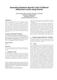
overall view is described later. The architecture is shown <strong>in</strong> figure 2.1 and it covers<br />
the relations between all software runn<strong>in</strong>g on one ECU. At the bottom of this diagram<br />
the ECU with the complete hardware is located. The other big layer is the Runtime<br />
<strong>Environment</strong> (RTE), which is arranged at a higher level. Everyth<strong>in</strong>g between the RTE<br />
and the hardware is called Basic Software (BSW) and this is the <strong>in</strong>frastructural basis<br />
to run other applications. The <strong>AUTOSAR</strong> software is arranged above the RTE layer<br />
and contributes the functional part of the software.<br />
Application Software<br />
Component<br />
<strong>AUTOSAR</strong> Interface<br />
Standardized<br />
Interface<br />
Operat<strong>in</strong>g<br />
System<br />
Standardized<br />
Interface<br />
Actuator Software<br />
Component<br />
<strong>AUTOSAR</strong> Interface<br />
Standardized<br />
<strong>AUTOSAR</strong> Interface<br />
Services<br />
Standardized<br />
Interface<br />
2.1.1 <strong>AUTOSAR</strong> Software<br />
Sensor Software<br />
Component<br />
<strong>AUTOSAR</strong> Interface<br />
Runtime <strong>Environment</strong> (RTE)<br />
Basic Software<br />
Standardized<br />
Interface<br />
Communication<br />
Standardized<br />
Interface<br />
ECU Hardware<br />
<strong>AUTOSAR</strong><br />
Software<br />
<strong>AUTOSAR</strong> Interface<br />
ECU Abstraction<br />
Standardized<br />
Interface<br />
Standardized<br />
Interface<br />
Microcontroller<br />
Abstraction Layer<br />
Figure 2.1: <strong>AUTOSAR</strong> architecture diagram<br />
Application Software<br />
Component<br />
<strong>AUTOSAR</strong> Interface<br />
<strong>AUTOSAR</strong> Interface<br />
Complex Device<br />
Drivers<br />
The <strong>AUTOSAR</strong> Software is realized by several Software Components (SWCs), which<br />
provide the functional behavior of the system. The communication between SWCs<br />
and other components or with parts of the BSW is done through the RTE 3 . In the<br />
diagram is a dist<strong>in</strong>ction of two k<strong>in</strong>ds of SWCs made:<br />
2<br />
An ECU is not just a microcontroller, it additionally consists of peripherals as e.g. flash–ROM,<br />
controller <strong>for</strong> bus systems or ASICs.<br />
3<br />
This also implies communications with components on other ECUs<br />
4
2.2 <strong>AUTOSAR</strong> basic approach<br />
<strong>AUTOSAR</strong> Software Component The <strong>AUTOSAR</strong> Software Component is <strong>in</strong>dependent<br />
from the underly<strong>in</strong>g hardware. That is done with the abstraction through<br />
the RTE and BSW.<br />
Sensor / Actuator Software Component This component depends on sensors<br />
and actuators which are available at the ECU. Due to per<strong>for</strong>mance such a component<br />
runs on the ECU to which the sensors and actuators are physically connected. Besides<br />
it is as <strong>in</strong>dependent as an <strong>AUTOSAR</strong> Software Component.<br />
2.1.2 Basic Software<br />
The BSW only provides <strong>in</strong>frastructural functionality to run the SWCs. In the follow<strong>in</strong>g<br />
is an overview of the several parts of the BSW given.<br />
Services This provides some basic services like e.g. memory and flash management<br />
and diagnostic protocols.<br />
Communication This are Communication stacks <strong>for</strong> <strong>in</strong>ter-ECU communication like<br />
e.g. <strong>Control</strong>ler Area Network (CAN) ([12]), Local Interconnect Network (LIN) ([2]),<br />
FlexRay ([1]), etc.<br />
Operat<strong>in</strong>g System The operat<strong>in</strong>g system provides priority based schedul<strong>in</strong>g of<br />
tasks and protection mechanisms. It is described <strong>in</strong> section 2.3 <strong>in</strong> more detail.<br />
Microcontroller Abstraction Layer (MCAL) To make the higher software layers<br />
<strong>in</strong>dependent from the microcontroller the MCAL is used. It avoids direct access<br />
to registers from higher–level software and abstracts features like e.g. digital I/O, or<br />
A/D converters. It is aimed to replace the microcontroller with another one without<br />
chang<strong>in</strong>g anyth<strong>in</strong>g at higher–level software. This assumes that a MCAL is available<br />
<strong>for</strong> the substitut<strong>in</strong>g controller.<br />
ECU abstraction S<strong>in</strong>ce the MCAL just abstracts the microcontroller the ECU<br />
abstraction does the same <strong>for</strong> the whole ECU.<br />
Complex Device Drivers Due to per<strong>for</strong>mance reasons the complex device drivers<br />
directly access the hardware.<br />
2.2 <strong>AUTOSAR</strong> basic approach<br />
After the architecture is clarified, this section takes a look at the basic approach of<br />
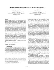
<strong>AUTOSAR</strong> <strong>for</strong> br<strong>in</strong>g<strong>in</strong>g software to ECUs. In <strong>AUTOSAR</strong> this is done <strong>in</strong> multiple<br />
steps. The approach shown <strong>in</strong> figure 2.2 handles the whole view of the complete system<br />
with multiple ECUs. The SWCs are developed us<strong>in</strong>g well def<strong>in</strong>ed <strong>in</strong>terfaces and<br />
they are connected through the Virtual Functional Bus (VFB). This is an abstract<br />
connection, that makes it possible <strong>for</strong> the components to <strong>in</strong>teract. It does not yet<br />
say someth<strong>in</strong>g about the later location of the SWC <strong>in</strong> the whole system and hides<br />
5
Chapter 2 <strong>AUTOSAR</strong><br />
the hardware dependency and the topology of the different ECUs and communication<br />
buses. To specify the requirements of SWCs on the hardware and <strong>in</strong>frastructure an<br />
XML–based configuration is used, which says what operations with which data elements<br />
are possible and what requirements to the <strong>in</strong>frastructure (<strong>in</strong> <strong>for</strong>m of functions<br />
and resources) are needed to run this SWC. It is also described, whether the SWC is<br />
available as source code or as object code.<br />
SWC1 SWC2 SWC3<br />
ECU descriptions<br />
SWC1<br />
ECU1<br />
RTE<br />
BSW<br />
SWC3<br />
Tool support<strong>in</strong>g<br />
deployment of SWC<br />
ECU2<br />
SWC2<br />
RTE<br />
BSW<br />
. . .<br />
SWCn<br />
Virtual Functional Bus<br />
. . .<br />
System constra<strong>in</strong>ts<br />
ECUm<br />
SWCn<br />
RTE<br />
BSW<br />
Figure 2.2: Basic <strong>AUTOSAR</strong> approach<br />
Together with the SWC description, a description <strong>for</strong> the system and <strong>for</strong> the ECUs<br />
must exist. The system description specifies the structure and constra<strong>in</strong>ts of the whole<br />
system. The ECU description def<strong>in</strong>es the resources and functions of every ECU. Together<br />
with this descriptions it is possible to map the SWCs to several ECUs, at<br />
which the RTE encapsulates the SWCs from everyth<strong>in</strong>g else. This means that the<br />
RTE provides the implementation of the VFB and hides the implementation of the<br />
communication <strong>for</strong> the SWCs. The components don’t get noticed about the communication,<br />
especially if it is an <strong>in</strong>tra– or <strong>in</strong>ter–ECU communication. The BSW at the<br />
bottom of each ECU provides the <strong>in</strong>frastructural functionality, as seen <strong>in</strong> the previous<br />
section.<br />
The idea is that the SWCs can be developed <strong>in</strong>dependent from the hardware and<br />
from other components as long as they use the standardized <strong>in</strong>terface and the description<br />
of the components is provided. With the VFB a complete separation of the<br />
applications and the <strong>in</strong>frastructure is provided. The SWCs can then be exchanged<br />
or <strong>in</strong>tegrated from other suppliers. The generation of the RTE is tool supported and<br />
6
2.3 <strong>AUTOSAR</strong> Operat<strong>in</strong>g System<br />
will be done automatically. A tool called the RTE generator is used, which is the<br />
ma<strong>in</strong> focus of this work. Such tools are not provided by the <strong>AUTOSAR</strong> consortium<br />
itself, but they are provided by tool–suppliers. Several different implementations of<br />
<strong>AUTOSAR</strong> tools, especially of RTE generators exist, but they shall all be compliant<br />
with the <strong>AUTOSAR</strong> standard.<br />
2.3 <strong>AUTOSAR</strong> Operat<strong>in</strong>g System<br />
In terms of a normal personal computer, the whole BSW would be called the operat<strong>in</strong>g<br />
system. However, <strong>for</strong> automotive architectures a strict dist<strong>in</strong>ction is done. The operat<strong>in</strong>g<br />
system is just a lightweight system, which provides schedul<strong>in</strong>g of tasks, event<br />
mechanisms and resource mechanisms. The resource mechanisms are used <strong>for</strong> the handl<strong>in</strong>g<br />
of mutual exclusive execution <strong>in</strong> critical sections and they have noth<strong>in</strong>g to do<br />
with physical resources.<br />
<strong>AUTOSAR</strong> def<strong>in</strong>es a standard <strong>for</strong> an operat<strong>in</strong>g system [4], which is based on the<br />
OSEK–OS standard [14]. One ma<strong>in</strong> attribute of this operat<strong>in</strong>g system is, that it is<br />
statically configured and typically the operat<strong>in</strong>g system is compiled and l<strong>in</strong>ked with all<br />
other software. The configuration is done with the OSEK Implementation Language<br />
(OIL), which is described <strong>in</strong> [15], until release 2.1. For release 3.0 this configuration<br />
has changed to an XML <strong>for</strong>mat [5] and so XML based descriptions are used <strong>for</strong> the<br />
whole <strong>AUTOSAR</strong> standard. Some basic features of the operat<strong>in</strong>g system are described<br />
<strong>in</strong> [4]. These are:<br />
• statical configuration<br />
• real–time per<strong>for</strong>mance<br />
• runs on low–end microcontroller without external resources<br />
• priority based schedul<strong>in</strong>g of tasks<br />
• protection mechanisms <strong>for</strong> memory access and tim<strong>in</strong>g<br />
The <strong>AUTOSAR</strong> specification <strong>for</strong> the operat<strong>in</strong>g system just ma<strong>in</strong>ly describes differences<br />
to OSEK–OS. So the follow<strong>in</strong>g explanations are based on the OSEK–OS specification<br />
([14]).<br />
2.3.1 Tasks<br />
Like other operat<strong>in</strong>g systems, OSEK–OS supports multitask<strong>in</strong>g. The scheduler of the<br />
operat<strong>in</strong>g system provides a priority–based schedul<strong>in</strong>g of tasks. A task def<strong>in</strong>es an<br />
execution of <strong>in</strong>structions, which are done <strong>in</strong> a sequential order. The different tasks<br />
are executed concurrent and asynchronous by the scheduler. OSEK–OS differentiates<br />
between two k<strong>in</strong>ds of tasks, which are expla<strong>in</strong>ed <strong>in</strong> the follow<strong>in</strong>g.<br />
7
Chapter 2 <strong>AUTOSAR</strong><br />
Basic task Basic tasks release the processor, only if they term<strong>in</strong>ate, the scheduler<br />
switches to a task with a higher priority or an <strong>in</strong>terrupt arises and an <strong>in</strong>terrupt service<br />
rout<strong>in</strong>e is called.<br />
Extended task The extended tasks provide <strong>in</strong> addition to the basic tasks the possibility<br />
to release the processor without term<strong>in</strong>ation and wait <strong>for</strong> an event. After the<br />
event occurs, the extended task can be waked up by the scheduler aga<strong>in</strong>. This is<br />
called a wait–po<strong>in</strong>t and can be used to synchronize tasks. Basic tasks can just be<br />
synchronized on the start or the end.<br />
ready<br />
start<br />
activate<br />
release<br />
suspend<br />
start<br />
preempt<br />
wait<br />
term<strong>in</strong>ate<br />
wait<br />
Figure 2.3: States of a Task<br />
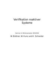
The scheduler works priority–based and a task can reach the states, which are shown<br />
<strong>in</strong> figure 2.3. The state “wait” can only be reached by an extended task. Only one<br />
task can be <strong>in</strong> state “run” at a time. “start” and “preempt” are the transitions, which<br />
are per<strong>for</strong>med by the scheduler to start or defer a task. The “term<strong>in</strong>ate” and “wait”<br />
transitions are done by the task itself. The “release” transition <strong>for</strong> an extended task<br />
is done by the operat<strong>in</strong>g system, if the event, which the task waits <strong>for</strong>, arises. The<br />
“activate” transition can be done <strong>in</strong> several ways. The operat<strong>in</strong>g system can switch<br />
the state of the task, if it is configured to be triggered by an operat<strong>in</strong>g system event<br />
and the event occurs. However, the transition can also be done with the operat<strong>in</strong>g<br />
system functions ActivateTask() or Cha<strong>in</strong>Task(). These functions can be called from<br />
every rout<strong>in</strong>e <strong>in</strong>clud<strong>in</strong>g the task itself.<br />
Due to the wait–po<strong>in</strong>ts the schedul<strong>in</strong>g and handl<strong>in</strong>g of an extended task takes more<br />
resources.<br />
2.3.2 Events<br />
Extended tasks can own one or more events. This are the events, the extended task<br />
can wait <strong>for</strong>. An event can be set from every other rout<strong>in</strong>e and it has to be cleared<br />
8<br />
run
2.4 Basic Concepts<br />
by the own<strong>in</strong>g task. If the task waits <strong>for</strong> an event and the event is set from another<br />
rout<strong>in</strong>e, the task will switch <strong>in</strong>to the state “ready”. At the beg<strong>in</strong>n<strong>in</strong>g of an extended<br />
task, that means at the transition from “suspended” to “ready”, all events of this task<br />
will be cleared from the operat<strong>in</strong>g system.<br />
2.3.3 Resources<br />
The resources of the operat<strong>in</strong>g system provide mutual exclusive access of tasks with<br />
different priorities to shared resources. If a task occupies a resource, no other task can<br />
do the same. So the task have to wait until the resource is released. That this wait<strong>in</strong>g<br />
cannot only be done <strong>in</strong> an extended task, the priority ceil<strong>in</strong>g protocol is used. This<br />
protocol <strong>in</strong>creases the priority of the task that occupies a resource. This is done dur<strong>in</strong>g<br />
the time, the resource is accessed. The priority is <strong>in</strong>creased to the highest priority of<br />
all tasks that can also access this resource. So it is prevented that another task, which<br />
can also access the resource, runs dur<strong>in</strong>g this time.<br />
2.4 Basic Concepts<br />
Some basic concepts and terms are now described <strong>in</strong> more detail. They are necessary<br />
<strong>for</strong> this work and to understand the RTE and the generat<strong>in</strong>g of the RTE. This description<br />
is based on the documents [6, 7, 3]. The second document is a specification<br />
of the VFB <strong>for</strong> release 3.0, because a version of this document <strong>for</strong> 2.1 does not exist.<br />
However, it conta<strong>in</strong>s the same mechanisms as release 2.1 and someth<strong>in</strong>g more that is<br />
not used here.<br />
2.4.1 Types<br />
To use data types <strong>in</strong> the software and especially with <strong>AUTOSAR</strong> mechanisms like the<br />
communication, this data types have to be specified. The simplest types that can be<br />
specified are the primitive types, which can be <strong>in</strong>tegers, str<strong>in</strong>gs, characters or Boolean<br />
types. This types are additionally specified with a range (or a length <strong>for</strong> str<strong>in</strong>gs), that<br />
says which values are possible. Exist<strong>in</strong>g types can be comb<strong>in</strong>ed to composite data<br />
types, which are an array or a record.<br />
2.4.2 Ports<br />
Ports are the mechanism of software components to communicate between each other.<br />
They def<strong>in</strong>e <strong>in</strong>teraction po<strong>in</strong>ts of a SWC. Several k<strong>in</strong>ds of ports are dist<strong>in</strong>guished. A<br />
port is either a required port or a provided port. A provided port offers data elements<br />
or services, a required port is the counterpart, which uses the data elements or services.<br />
This dist<strong>in</strong>ction describes the direction of the communication. Another classification is<br />
the k<strong>in</strong>d of the communication, which is divided <strong>in</strong>to sender–receiver and client–server<br />
9
Chapter 2 <strong>AUTOSAR</strong><br />
communications. These are described <strong>in</strong> the follow<strong>in</strong>g along with their symbols 4 to<br />
draw such a connection. The symbols are shown <strong>in</strong> figure 2.4.<br />
sender receiver client server<br />
Figure 2.4: Symbols <strong>for</strong> ports<br />
sender–receiver The sender distributes data to every receiver. Additionally, a<br />
mode manager can notify mode switches to the receivers. The direction of the communication<br />
is given through the arrow. Connections of the <strong>for</strong>m 1 : N and N : 1 are<br />
possible. M : N connections are explicitly not allowed because of the complexity of<br />
the implementation. One sender port can send multiple data elements and multiple<br />
modes. The sender is <strong>in</strong> this case the provided port, the receiver is the required port.<br />
client–server The server provides an operation which can be <strong>in</strong>voked by the client.<br />
So the server is accessed via the provided port <strong>for</strong> this case, whereas the client is called<br />
via the required port. The client can send values and the server can return values.<br />
Here only connections of the <strong>for</strong>m N : 1 are possible. One server port can provide<br />
multiple operations. An operation receives multiple values, does a calculation and<br />
then it can return multiple results.<br />
In both cases a required port, this is a receiver or a client, has to be connected. On<br />
the other hand a provided port, this means analogous a server or sender, can be left<br />
unconnected.<br />
The data elements and modes or the operations that are provided via a port are<br />
specified by the <strong>in</strong>terface of this port. They may be used to create multiple ports with<br />
the same <strong>in</strong>terface <strong>for</strong> one or different SWCs.<br />
Ports with the same or a compatible <strong>in</strong>terface can be connected. Compatible means<br />
that the provided port at least provides the operations or data types as <strong>for</strong> the required<br />
port specified. The provided port can provide more data or operations, which is not<br />
used by the required port.<br />
2.4.3 Software Components<br />
The SWCs are the applications which run on an <strong>AUTOSAR</strong> <strong>in</strong>frastructure. They<br />
<strong>in</strong>teract only through ports with other components. Thus, they can be developed<br />
<strong>in</strong>dependent from the hardware or from other components.<br />
4 To come back to the release discussion, the <strong>in</strong>troduced symbols are specified <strong>in</strong> release 3.0. The<br />
older release 2.1 uses other symbols, but the newer are much easier to draw and the mean<strong>in</strong>g is<br />
clearer<br />
10
Atomic Software Components<br />
2.4 Basic Concepts<br />
An atomic Software Components is a basic component, which provides an own behavior.<br />
The behavior is given with the later described <strong>in</strong>ternal behavior. An atomic<br />
Software Component can provide ports to allow communications with other components.<br />
Compositions<br />
Composition<br />
SWC1<br />
SWC2<br />
SWC3<br />
Figure 2.5: Composition of SWCs<br />
Compositions are another <strong>for</strong>m of a SWC which consists of other components. The<br />
components are aggregated to create a new component. Figure 2.5 shows such a<br />
composition of three SWCs. The ports from the components can be connected between<br />
each other or with ports of the composition. A connection between components <strong>in</strong>side<br />
the composition is called an assembly connector. A connection from a conta<strong>in</strong>ed<br />
component to a port of the composition is called a delegation connector.<br />
A composition of components just provides the behavior that results by the connections<br />
of the conta<strong>in</strong>ed components. It does not add an own implementation or own<br />
functionality.<br />
2.4.4 Internal Behavior<br />
A component can not only provide ports, there also have to be some functionality<br />
beh<strong>in</strong>d it. This is done by specify<strong>in</strong>g an <strong>in</strong>ternal behavior <strong>for</strong> an atomic Software<br />
Component. The <strong>in</strong>ternal behavior consists of several parts.<br />
Runnable Entities<br />
The functionality of an atomic Software Component is implemented <strong>in</strong> the <strong>for</strong>m of<br />
runnable entities or <strong>in</strong> short runnables. Runnables are executed when a special event<br />
arises and they are implemented <strong>in</strong> <strong>for</strong>m of a C or C ++ function. A runnable can<br />
access the ports of the SWC. The description <strong>for</strong> this is done with different po<strong>in</strong>ts or<br />
accesses.<br />
DataSendPo<strong>in</strong>t It describes an access to a sender port and a concrete data element<br />
of that port. The value, which is written to the port, is directly available.<br />
11
Chapter 2 <strong>AUTOSAR</strong><br />
DataReceivePo<strong>in</strong>t It describes an access to a client port and a concrete data element<br />
of that port. The value, which is returned, is the current value.<br />
DataWriteAccess It describes an implicit access to a sender port and a concrete<br />
data element of that port. The runnable can access the port multiple times, but just<br />
the last written value will be available at the port after term<strong>in</strong>ation of the runnable.<br />
DataReadAccess It describes an implicit access to a receiver port and a concrete<br />
data element of that port. The runnable can access the port multiple times dur<strong>in</strong>g<br />
one execution and will get the same value every time.<br />
AsynchronousServerCallPo<strong>in</strong>t A runnable calls a server with an asynchronous<br />
call through a client port. It has to be specified, which client port and which provided<br />
operation is used. An asynchronous call returns directly <strong>for</strong> the <strong>in</strong>vok<strong>in</strong>g runnable.<br />
The result is not available by now, <strong>in</strong>stead it has to be fetched later by another call<br />
when the operation is f<strong>in</strong>ished.<br />
SynchronousServerCallPo<strong>in</strong>t A runnable calls a server with an synchronous call<br />
through a client port. It has to be specified, which client port and which provided<br />
operation is used. A synchronous call returns not until the operation is f<strong>in</strong>ished and<br />
the result is available.<br />
WaitPo<strong>in</strong>t A special item <strong>in</strong> this enumeration is the WaitPo<strong>in</strong>t. All other items<br />
refers to a port and a special data element or operation of the port. Instead of that<br />
a WaitPo<strong>in</strong>t refers an RTE event <strong>for</strong> which can be waited. The call does not return<br />
until the event or a specified timeout occurs.<br />
It can be seen <strong>in</strong> this enumeration, that the accesses are described <strong>in</strong> very detail. So<br />
e.g. a runnable can read a data element of a port directly and another data element<br />
of the same port with an implicit access.<br />
RTE Events<br />
For the RTE some events can be specified. An event can either trigger a runnable or<br />
wake up a WaitPo<strong>in</strong>t. The follow<strong>in</strong>g events are def<strong>in</strong>ed by <strong>AUTOSAR</strong>.<br />
Tim<strong>in</strong>gEvent For this event an <strong>in</strong>terval and an offset has to be specified. So the<br />
po<strong>in</strong>ts <strong>in</strong> time are given at which the event occurs.<br />
DataReceivedEvent This event is specified <strong>for</strong> a receiver port and <strong>for</strong> a concrete<br />
data element of the port. It occurs when new data is received.<br />
DataReceivedErrorEvent This event is also specified <strong>for</strong> a receiver port and <strong>for</strong><br />
a concrete data element of the port. But it occurs when data is <strong>in</strong>validated <strong>for</strong> a<br />
communication.<br />
DataSendCompletedEvent The DataSendCompletedEvent have to be specified<br />
<strong>for</strong> a sender port and a DataSendPo<strong>in</strong>t. It occurs when the send<strong>in</strong>g of a data element<br />
is completed.<br />
12
2.4 Basic Concepts<br />
OperationInvokedEvent This event is called when an operation <strong>for</strong> a server port<br />
is <strong>in</strong>voked. The event is specified with the port and with the operation <strong>for</strong> which it<br />
should occur.<br />
AsynchronousServerCallReturnsEvent If an asynchronous call is used to <strong>in</strong>voke<br />
an operation on a server, the result of the server call can be fetched at later time. This<br />
event shows, that the server is f<strong>in</strong>ished and the result is available. It is specified <strong>for</strong> a<br />
client port and an operation, which is called by the client.<br />
ModeSwitchEvent For this event a mode and an action “entry” or “exit” has to<br />
be specified. The event arises when the specified mode is entered or exited, depend<strong>in</strong>g<br />
on which action is specified.<br />
Every event can trigger a runnable, but not every event can wake up a WaitPo<strong>in</strong>t.<br />
The events, which can wake up a WaitPo<strong>in</strong>t, are DataReceivedEvents, DataSendCompletedEvents<br />
and AsynchronousServerCallReturnsEvents.<br />
Inter Runnable Variable<br />
Ports def<strong>in</strong>e the <strong>in</strong>teraction between SWCs, or more precise the <strong>in</strong>teraction between<br />
the runnables of the SWCs. For runnables of one SWC another mechanism <strong>for</strong> <strong>in</strong>ternal<br />
communication exists. These are the Inter Runnable Variables (IRVs), which can be<br />
accessed by the runnables. Runnables could also use global variables <strong>for</strong> this <strong>in</strong>ternal<br />
communication, but with IRVs protection mechanism are provided by the RTE <strong>for</strong><br />
concurrency.<br />
Exclusive Area<br />
Exclusive Area are a similar mechanism to the operat<strong>in</strong>g system resources described <strong>in</strong><br />
section 2.3.3. Exclusive areas just provide mutual exclusive access <strong>for</strong> the runnables of<br />
one SWC, but not <strong>for</strong> the whole task. Exclusive areas can be implemented with operat<strong>in</strong>g<br />
system resources, but this is no requirement. There can be other implementation<br />
possibilities specified like e.g. <strong>in</strong>terrupt–disabl<strong>in</strong>g.<br />
2.4.5 Modes<br />
Modes have the simple purpose that components can provide a different behavior<br />
depend<strong>in</strong>g on which mode is active. The mode can be distributed from a component<br />
through ports to other components. Typical modes <strong>for</strong> a motor control unit are<br />
“Start”, “Drive” and “Stop”.<br />
A mode has to be distributed through a port, because there must be the possibility<br />
to provide modes to other ECUs. RTE Events can be disabled <strong>in</strong> a mode. Then<br />
the event is prevented, if a special mode is active. This makes it possible to execute<br />
runnables just <strong>in</strong> one mode. A ModeSwitchEvent responds directly to a mode switch.<br />
It triggers a runnable if a special mode is entered or left. These runnables can be used<br />
to clean up the old mode or prepare the new mode.<br />
13
Chapter 2 <strong>AUTOSAR</strong><br />
mode<br />
A<br />
mode<br />
dependent<br />
runnables<br />
mode<br />
switch<br />
<strong>in</strong>dication<br />
OnExit<br />
runnables<br />
OnEntry<br />
runnables<br />
transisiton<br />
mode <strong>in</strong>dependent runnables<br />
time<br />
Figure 2.6: Sequence of a mode switch<br />
mode<br />
dependent<br />
runnables<br />
mode<br />
B<br />
The <strong>AUTOSAR</strong> specification def<strong>in</strong>es a concrete sequence <strong>for</strong> a mode switch. This<br />
sequence is shown <strong>in</strong> figure 2.6 with a switch from mode “A” to mode “B”. If a mode<br />
switch is <strong>in</strong>dicated, first all runnables that depend on the active mode have to be<br />
f<strong>in</strong>ished. After that, the OnExit runnables <strong>for</strong> mode “A” are executed. Then the<br />
OnEntry runnables <strong>for</strong> mode “B” are executed. Afterwards the new mode “B” is<br />
reached and the runnables depend<strong>in</strong>g on this mode can be executed. However, this<br />
depends on the events, trigger<strong>in</strong>g these runnables. Runnables that do not depend on<br />
a mode are not affected from the mode switch.<br />
In the diagram it can be seen, that after the mode switch <strong>in</strong>dication it has to be<br />
waited <strong>for</strong> the term<strong>in</strong>ation of all mode depend<strong>in</strong>g runnables that depend on mode “A”.<br />
For this reason the <strong>AUTOSAR</strong> specification prohibits that a runnable, which depends<br />
on a mode, can have a WaitPo<strong>in</strong>t.<br />
2.5 Virtual Functional Bus<br />
An abstract mechanism <strong>for</strong> connect<strong>in</strong>g SWCs called the VFB has been <strong>in</strong>troduced<br />
<strong>in</strong> the section 2.2. It allows to develop SWCs <strong>in</strong>dependent from other hardware and<br />
software by provid<strong>in</strong>g a def<strong>in</strong>ed <strong>in</strong>terface. For this <strong>in</strong>terface, the ports are def<strong>in</strong>ed and<br />
can be used from the functions <strong>in</strong> the component. At the VFB level, this ports can<br />
be used to connect components by connect<strong>in</strong>g compatible ports.<br />
In figure 2.7 is a connection of some components shown. This represents the functional<br />
part of the system, <strong>in</strong>dependent from the architecture or <strong>in</strong>frastructure which<br />
is needed to execute this system.<br />
14
SWC1 SWC2 SWC3<br />
2.6 Configuration Files<br />
. . .<br />
Figure 2.7: VFB diagram<br />
SWCn<br />
Virtual Functional Bus<br />
2.6 Configuration Files<br />
To do the mapp<strong>in</strong>g to the ECUs, which is described <strong>in</strong> section 2.2, it is necessary to<br />
know a lot of <strong>in</strong><strong>for</strong>mation about every part of the <strong>AUTOSAR</strong> system. This means<br />
the precise description of a SWC <strong>for</strong> each mechanism described <strong>in</strong> section 2.4 and<br />
the configuration of the ECUs and the system. This configuration is done <strong>in</strong> an<br />
XML <strong>for</strong>mat <strong>for</strong> a def<strong>in</strong>ed XML scheme. The concrete XML scheme depends on the<br />
<strong>AUTOSAR</strong> release. For one release some different scheme versions can exist, as a<br />
result of bug fixes and updates.<br />
<strong>AUTOSAR</strong> dist<strong>in</strong>guishes two cases of specifications. The specification of a SWC<br />
together with its <strong>in</strong>ternal behavior is called a SWC description. Everyth<strong>in</strong>g that goes<br />
beyond the scope of a s<strong>in</strong>gle component is called a configuration. Together with a<br />
SWC description it is possible to deliver the component to suppliers.<br />
<strong>AUTOSAR</strong> does not specify, which <strong>in</strong><strong>for</strong>mation has to be put <strong>in</strong> which files. Instead<br />
the structure of the files is flexible that the whole configuration can be put <strong>in</strong> one file<br />
or every object can have its own file. To reference an object <strong>in</strong> an XML file a unique<br />
path is used, which consists of the package names that have to traversed <strong>in</strong> the XML<br />
tree to reach this object. An example is given <strong>in</strong> section 2.8.<br />
2.7 Runtime <strong>Environment</strong><br />
The RTE is the implementation of the VFB <strong>for</strong> one specific ECU. It provides the<br />
environment which is needed <strong>for</strong> the SWCs to run on that ECU and communicate with<br />
other SWCs. The RTE encapsulates the communication between the components, so<br />
that they don’t know were the counterpart of the communication is located. This<br />
means, that the communication with a component on the same ECU is done directly,<br />
whereas the communication with a component, which is located elsewhere, is done<br />
through a communication mechanism like CAN or LIN. But the RTE does more than<br />
just provide the connections of the VFB. It additionally ensures that runnables of a<br />
SWC are triggered through the configured events, provides consistency <strong>for</strong> IRVs and<br />
ensures the effect of exclusive areas. Or <strong>in</strong> short, it provides the functions <strong>for</strong> all the<br />
configured mechanisms.<br />
As earlier described the RTE is auto generated from the RTE generator but this is<br />
15
Chapter 2 <strong>AUTOSAR</strong><br />
not absolutely true. Some parts of the RTE are fixed and have not to be generated<br />
every time. This files are called the RTE library. However they are delivered with the<br />
RTE generator to cooperate with the generated code.<br />
The RTE generator shall provide two different phases, which can be used <strong>in</strong> different<br />
development stages. This two phases can be split <strong>in</strong>to two tools, but they are very<br />
similar and the currently known generators support both.<br />
Contract phase In the contract phase an RTE generator shall produce the header<br />
files <strong>for</strong> the SWCs to allow compil<strong>in</strong>g the components. It is not necessary to def<strong>in</strong>e<br />
the whole system <strong>in</strong> this case, but just the SWCs <strong>for</strong> which the header files should<br />
be generated. The header files just conta<strong>in</strong> the Application Programm<strong>in</strong>g Interface<br />
(API), which can be used from the SWCs.<br />
Generat<strong>in</strong>g phase In this phase the generator shall produce the whole RTE <strong>for</strong> one<br />
ECU. The generated RTE also consists of header files <strong>for</strong> the SWCs and these have to<br />
be compliant with those generated <strong>in</strong> the contract phase.<br />
Together with that, the RTE generator normally works <strong>in</strong> a mode called the “compatibility<br />
mode”. It can additionally support an optional mode, which is called the<br />
“vendor mode”. A description of both is given <strong>in</strong> the follow<strong>in</strong>g.<br />
Compatibility mode The RTE generator produces well–def<strong>in</strong>ed data structures<br />
and types <strong>in</strong> this mode. That means, that not only the API <strong>for</strong> the SWCs is def<strong>in</strong>ed,<br />
but also a lot of the implementation beh<strong>in</strong>d this API. There are e.g. structures to<br />
provide access to the current values of a sender–receiver communication. This mode<br />
has its ma<strong>in</strong> focus on the shar<strong>in</strong>g of object code between different suppliers.<br />
Vendor mode This is an optional mode, <strong>in</strong> which the RTE generator can assume<br />
that the RTE is created only with that one generator (or maybe compatible generators<br />
from the same vendor). So it does not have to create that well–def<strong>in</strong>ed implementation<br />
of the API from compatibility mode and it can produce more efficient code and do<br />
optimizations.<br />
The source code <strong>in</strong> the contract phase also have to conta<strong>in</strong> the tasks, which are specified<br />
<strong>in</strong> the configuration and <strong>in</strong> which context the runnables are executed. The code<br />
<strong>for</strong> the tasks have to provide calls <strong>for</strong> the runnables, because they shall be executed<br />
if the configured events occur. Additionally the RTE generator shall output a part<br />
of the configuration <strong>for</strong> the operat<strong>in</strong>g system. This is necessary, that the operat<strong>in</strong>g<br />
system gets noticed about the tasks and how they should be executed. The example<br />
<strong>in</strong> the next section also addresses this po<strong>in</strong>t.<br />
2.8 Example<br />
This is a short example to clarify the concepts and proceed<strong>in</strong>gs described <strong>in</strong> this<br />
chapter. It especially focuses the view of the implementation and the generat<strong>in</strong>g of<br />
16
2.8 Example<br />
the RTE and should clarify how components can be implemented and how the API<br />
can be used.<br />
2.8.1 Configuration of the Example<br />
The example is based on a system with two SWCs, which are shown <strong>in</strong> figure 2.8. This<br />
section just conta<strong>in</strong>s an extract of the configuration and some parts of the source code<br />
<strong>for</strong> SWC1. To whole configuration of the system can be found <strong>in</strong> appendix A. The<br />
configuration of the ECU is not shown.<br />
SWC1<br />
run11 run12<br />
SWC2<br />
run21 run22<br />
Virtual Functional Bus<br />
Figure 2.8: Visualization of the example<br />
Task1<br />
Task2<br />
Every SWC uses two ports and has two runnables, which are shown as boxes <strong>in</strong>side<br />
of the components. The l<strong>in</strong>es to the ports show an access to this ports. The runnable<br />
run11 is triggered by a tim<strong>in</strong>g event which occurs every 100ms. Runnable run12 is<br />
triggered by another tim<strong>in</strong>g event which occurs every 50ms. The two runnables of<br />
SWC1 are mapped to the same task Task1. In more detail the events trigger<strong>in</strong>g a<br />
runnable are mapped to a task, but here every runnable is just triggered by one event<br />
and so they only run <strong>in</strong> the context of one Task. The runnable run22 of SWC2 is<br />
also triggered by an tim<strong>in</strong>g event every 50ms and runs <strong>in</strong> the context of Task2. The<br />
other runnable run21 is triggered by the <strong>in</strong>vocation of a server call at the server port.<br />
This runnable is not mapped to a task, but is has the option set, that it can be<br />
<strong>in</strong>voked concurrently. This is one special case, where an event must not be mapped<br />
to a task. Instead a direct call to the runnable should be per<strong>for</strong>med to provide a<br />
better per<strong>for</strong>mance. Both SWCs are mapped to the same ECU. All this <strong>in</strong><strong>for</strong>mation<br />
is reflected by the configuration files.<br />
List<strong>in</strong>g 2.1 shows the def<strong>in</strong>ition of the data elements which are used <strong>for</strong> this example.<br />
The first is the <strong>in</strong>teger type Int16 with a specified range of valid values. The second<br />
type is a str<strong>in</strong>g type, which has a length of 8 characters and the symbol Str<strong>in</strong>g8. To<br />
reference a type, the names of the packages have to be used as path. This means <strong>for</strong><br />
the <strong>in</strong>teger type, that it can be referenced by the path /types/Int16.<br />
The description of the <strong>in</strong>terface of the sender–receiver port used <strong>in</strong> the example is<br />
shown <strong>in</strong> list<strong>in</strong>g 2.2. The <strong>in</strong>terface SR Int16 consists of two data elements <strong>in</strong>tValue1<br />
and <strong>in</strong>tValue2, which are both of type Int16, and it provides a not queued communication.<br />
Here it is shown, how the reference to the data types are used multiple times.<br />
The package names specified <strong>in</strong> the list<strong>in</strong>gs are arbitrary. There is no need to call<br />
17
Chapter 2 <strong>AUTOSAR</strong><br />
1 <br />
<br />
<br />
<br />
types<br />
<br />
<br />
Int16<br />
-32768<br />
10 32767<br />
<br />
<br />
Str<strong>in</strong>g8<br />
utf8<br />
8<br />
<br />
<br />
<br />
<br />
20 <br />
List<strong>in</strong>g 2.1: Example description of data types<br />
1 <br />
<br />
<br />
<br />
<strong>in</strong>terfaces<br />
<br />
<br />
SR Int16<br />
false<br />
10 <br />
<br />
<strong>in</strong>tValue1<br />
/types/Int16<br />
false<br />
<br />
<br />
<strong>in</strong>tValue2<br />
/types/Int16<br />
false<br />
20 <br />
<br />
<br />
<br />
<br />
<br />
<br />
18<br />
List<strong>in</strong>g 2.2: Example description of port <strong>in</strong>terfaces
2.8 Example<br />
them “types” or “ <strong>in</strong>terfaces ”. Additionally, it is not needed to have different names<br />
<strong>for</strong> these packages.<br />
1 <br />
<br />
<br />
<br />
swc root<br />
<br />
<br />
swc1<br />
<br />
10 <br />
pport1<br />
/<strong>in</strong>terfaces/SR Int16<br />
<br />
<br />
rport1<br />
/<strong>in</strong>terfaces/CS str<strong>in</strong>g to <strong>in</strong>t<br />
<br />
<br />
<br />
20 <br />
<br />
<br />
<br />
List<strong>in</strong>g 2.3: Example description of SWC1<br />
To describe the component SWC1, the code of list<strong>in</strong>g 2.3 is used. Here are the two<br />
ports of SWC1 specified. List<strong>in</strong>g 2.4 shows the <strong>in</strong>ternal behavior of SWC1. There are<br />
the runnables and the ports, which are accessed by the runnables, described. This is<br />
needed to generate the API and to provide consistency <strong>for</strong> the communication. The<br />
access is specified with DataSendPo<strong>in</strong>ts and a SynchronousServerCallPo<strong>in</strong>t. Runnable<br />
run11 writes both values to the sender port pport11, whereas run12 only writes the<br />
value <strong>in</strong>tValue1.<br />
The runnables are triggered by the specified tim<strong>in</strong>g events. One runnable can be<br />
triggered by more than one event, but this case is not shown here.<br />
At this po<strong>in</strong>t it can be seen that every part is very flexible handled with references. It<br />
is also permitted to have more than one <strong>in</strong>ternal behavior <strong>for</strong> one Software Component<br />
specified, but just one can be used. This is done by the <strong>in</strong>stantiation of the SWC, which<br />
is part of the system description and not shown here. So it is e.g. possible to reuse a<br />
def<strong>in</strong>ition of a Software Component and reuse it with different <strong>in</strong>ternal behaviors. As<br />
also can be seen <strong>in</strong> the configuration, it is possible <strong>for</strong> an <strong>in</strong>ternal behavior to support<br />
multiple <strong>in</strong>stantiation, which should also not be considered here, because it does not<br />
contribute to the understand<strong>in</strong>g and would just complicate the example.<br />
2.8.2 The Generated Source Code<br />
After call<strong>in</strong>g the RTE generator with that configuration, it should produce the auto<br />
generated part of the RTE. This part conta<strong>in</strong>s the API <strong>for</strong> the SWCs. The <strong>in</strong>terest<strong>in</strong>g<br />
extract <strong>for</strong> SWC1 is shown <strong>in</strong> list<strong>in</strong>g 2.5. In the last two l<strong>in</strong>es the functions <strong>for</strong> the<br />
runnables are declared. These functions are called when a runnable is executed. This<br />
means <strong>for</strong> this example that the functions are called when the tim<strong>in</strong>g events occur. So<br />
19
Chapter 2 <strong>AUTOSAR</strong><br />
1 <br />
<br />
<br />
<br />
swc root<br />
<br />
<br />
<strong>in</strong>tBehSwc1<br />
/swc root/swc1<br />
10 <br />
<br />
Time100ms<br />
/swc root/<strong>in</strong>tBehSwc1/run11<br />
0.1<br />
<br />
<br />
Time50ms<br />
/swc root/<strong>in</strong>tBehSwc1/run12<br />
0.05<br />
20 <br />
<br />
<br />
<br />
run11<br />
false<br />
<br />
<br />
dwa1<br />
<br />
30 /swc root/swc1/pport1<br />
<br />
/<strong>in</strong>terfaces/SR Int16/<strong>in</strong>tValue1<br />
<br />
<br />
<br />
<br />
dwa2<br />
<br />
/swc root/swc1/pport1<br />
40 <br />
/<strong>in</strong>terfaces/SR Int16/<strong>in</strong>tValue2<br />
<br />
<br />
<br />
<br />
run11<br />
<br />
<br />
run12<br />
50 false<br />
<br />
<br />
dwa2<br />
<br />
/swc root/swc1/pport1<br />
<br />
/<strong>in</strong>terfaces/SR Int16/<strong>in</strong>tValue1<br />
<br />
<br />
60 <br />
<br />
<br />
<br />
sscp<br />
<br />
<br />
<br />
/swc root/swc1/rport1<br />
<br />
70 <br />
/<strong>in</strong>terfaces/CS str<strong>in</strong>g to <strong>in</strong>t/parse<br />
<br />
<br />
<br />
<br />
<br />
run12<br />
<br />
<br />
80 false<br />
<br />
<br />
<br />
<br />
<br />
20<br />
List<strong>in</strong>g 2.4: Example description of <strong>in</strong>ternal behavior of SWC1
1 #def<strong>in</strong>e RTE E CS str<strong>in</strong>g to <strong>in</strong>t overflow (42)<br />
#def<strong>in</strong>e RTE E CS str<strong>in</strong>g to <strong>in</strong>t underflow (43)<br />
2.8 Example<br />
#def<strong>in</strong>e Rte Call rport1 parse(array, sum) (Rte Call swc1 rport1 parse(array, sum))<br />
FUNC(Std ReturnType, RTE CODE) Rte Call swc1 rport1 parse(CONSTP2VAR(Str<strong>in</strong>g8, �<br />
AUTOMATIC, RTE APPL DATA), CONSTP2VAR(Int16, AUTOMATIC, RTE APPL DATA));<br />
/∗ Inl<strong>in</strong>e Write optimization; Rte Write pport1 <strong>in</strong>tValue2 to direct access ∗/<br />
extern VAR(Int16, RTE DATA) Rte RxBuf 1;<br />
10 #def<strong>in</strong>e Rte Write pport1 <strong>in</strong>tValue2(data) ( �<br />
Rte WriteHook swc1 pport1 <strong>in</strong>tValue2 Start(data), (Rte RxBuf 1 = data), �<br />
Rte WriteHook swc1 pport1 <strong>in</strong>tValue2 Return(data), RTE E OK )<br />
/∗ Inl<strong>in</strong>e Write optimization; Rte Write pport1 <strong>in</strong>tValue1 to direct access ∗/<br />
extern VAR(Int16, RTE DATA) Rte RxBuf 0;<br />
#def<strong>in</strong>e Rte Write pport1 <strong>in</strong>tValue1(data) ( �<br />
Rte WriteHook swc1 pport1 <strong>in</strong>tValue1 Start(data), (Rte RxBuf 0 = data), �<br />
Rte WriteHook swc1 pport1 <strong>in</strong>tValue1 Return(data), RTE E OK )<br />
FUNC(void, RTE APPL CODE) run11(void);<br />
FUNC(void, RTE APPL CODE) run12(void);<br />
List<strong>in</strong>g 2.5: Example header file <strong>for</strong> SWC1 (Rte swc1.h)<br />
to implement a functional behavior <strong>for</strong> the Software Component, this functions have<br />
to be implemented. With<strong>in</strong> these functions, the values of the ports can be accessed, if<br />
it is configured <strong>for</strong> the SWC.<br />
For an access to a sender port with a DataSendPo<strong>in</strong>t, the API is specified with<strong>in</strong><br />
<strong>AUTOSAR</strong> to be of the <strong>for</strong>m Rte Write (data). Whereas is the name<br />
of the port and is the name of the data element which is accessed. The value,<br />
which is passed to the call with the parameter data, is written to the port.<br />
As mentioned be<strong>for</strong>e, the both components are mapped to the same ECU and so<br />
there is no need to use any <strong>in</strong>ter–ECU communication mechanism. Instead the communication<br />
can be done directly. It can be seen <strong>in</strong> the example that the API is<br />
implemented with #def<strong>in</strong>e directives, which directly accesses the global variables<br />
Rte RxBuf 1 and Rte RxBuf 2. The API <strong>for</strong> SWC2 is not shown here, but it has to<br />
access the same variables to establish the communication.<br />
To <strong>in</strong>voke an operation at the server, a function call is necessary. For the runnable<br />
run12 is a SynchronousServerCallPo<strong>in</strong>t specified. So the function does not return<br />
until the operation on the server is f<strong>in</strong>ished and the return values are available. In<br />
the special case mentioned above, the runnable, which implements the server, is not<br />
mapped to a task and can be <strong>in</strong>voked concurrently. This runnable is then executed <strong>in</strong><br />
the context of the current task and therewith no other task has to be started.<br />
For the SynchronousServerCallPo<strong>in</strong>t, the API Rte Call rport1 parse( str<strong>in</strong>g , value)<br />
is expected and created by the RTE generator. The operation parse takes one str<strong>in</strong>g<br />
as argument and returns one <strong>in</strong>teger value. This API is implemented us<strong>in</strong>g a #def<strong>in</strong>e<br />
directive to a function. This function is implemented <strong>in</strong> the also generated file Rte.c.<br />
21
Chapter 2 <strong>AUTOSAR</strong><br />
1 TASK(Task1)<br />
{<br />
Rte RECount Task1 divby2 0−−;<br />
if ( Rte RECount Task1 divby2 0 == 0 )<br />
{<br />
run11();<br />
}<br />
{<br />
run12();<br />
10 }<br />
if ( Rte RECount Task1 divby2 0 == 0 )<br />
{<br />
Rte RECount Task1 divby2 0 = 2;<br />
}<br />
Term<strong>in</strong>ateTask();<br />
}<br />
List<strong>in</strong>g 2.6: Example code <strong>for</strong> Task1<br />
The RTE generator also creates the source code <strong>for</strong> the tasks. The extract <strong>for</strong> Task1<br />
is shown <strong>in</strong> list<strong>in</strong>g 2.6. Here it can be seen that the runnable run11 is triggered every<br />
100ms and runnable run12 every 50ms. This is done by activat<strong>in</strong>g the task every<br />
50ms and execut<strong>in</strong>g the runnable run11 just any second call. The activation of the<br />
task every 50ms is done <strong>in</strong> the configuration of the operat<strong>in</strong>g system, which is also<br />
created from the generator.<br />
2.8.3 Implement<strong>in</strong>g the Runnables<br />
At the end list<strong>in</strong>g, 2.7 shows how the runnable run12 can be implemented. The created<br />
API can be used to access the ports. Here it is just necessary to write the correct API<br />
to the source code. This code can then be compiled with the generated header file.<br />
Instead of the global variables <strong>for</strong> the sender–receiver communication shown <strong>in</strong> this<br />
example, also a function call can be used. The runnable would not get noticed about<br />
it.<br />
1 FUNC(void, RTE APPL CODE) run12(void)<br />
{<br />
Str<strong>in</strong>g8 val1;<br />
Int16 val2;<br />
...<br />
6 Rte Call rport1 parse(val1, &val2);<br />
...<br />
8 Rte Write pport1 <strong>in</strong>tValue1(val2);<br />
...<br />
10 }<br />
List<strong>in</strong>g 2.7: Example code <strong>for</strong> run12<br />
This also shows the first problem <strong>for</strong> shar<strong>in</strong>g object code. If a component is compiled<br />
aga<strong>in</strong>st such a header file with global variables, it is expected that a generator, which<br />
creates the whole API, does not create the same global variable. So the object code<br />
22
2.9 Summary<br />
cannot be used. There<strong>for</strong>e function calls have to be created <strong>for</strong> shar<strong>in</strong>g object code.<br />
But this causes an overhead <strong>for</strong> the function <strong>in</strong>vocation when access<strong>in</strong>g a port.<br />
2.8.4 Conclusion of the Example<br />
This simple example shows some basic mechanisms def<strong>in</strong>ed <strong>in</strong> <strong>AUTOSAR</strong>. It presents<br />
the complexity of the XML configuration which is already reached by such a simple<br />
case. But it should help to understand, how the mechanisms described <strong>in</strong> this chapter<br />
are implemented <strong>in</strong> the source code.<br />
2.9 Summary<br />
In summary <strong>AUTOSAR</strong> allows a strict dist<strong>in</strong>ction between functional parts (SWCs)<br />
of software and <strong>in</strong>frastructural parts (BSW), which just provides the necessary basis<br />
to run the SWCs. The functional components are developed <strong>in</strong>dependent with respect<br />
to <strong>AUTOSAR</strong> compliant <strong>in</strong>terfaces and descriptions, which specify <strong>in</strong> a <strong>for</strong>mal and<br />
detailed way, what resources are necessary to run a component. Additionally, it has<br />
to be specified, which conditions are provided by the hardware and the topology of<br />
the system. Then, the RTE generator creates automatically the RTE, which br<strong>in</strong>gs<br />
the two parts (SWCs and BSW) together.<br />
With the standardization of the BSW and the <strong>in</strong>terfaces between each part of the<br />
BSW, the replaceability of parts <strong>in</strong>creases and even with the MCAL it is possible<br />
to exchange microcontrollers with others, if there are <strong>AUTOSAR</strong> compliant MCALs<br />
available <strong>for</strong> the new controllers.<br />
23
Chapter 2 <strong>AUTOSAR</strong><br />
24
Chapter 3<br />
MEDC17<br />
<strong>AUTOSAR</strong> is a new standard, which is described <strong>in</strong> the previous chapter. The currently<br />
from BOSCH developed and used environment <strong>for</strong> software of motor control<br />
units is called MEDC17. It is not a standard as <strong>AUTOSAR</strong>, but just an environment<br />
consist<strong>in</strong>g of a software architecture and application software together with a build<br />
environment. The control unit, which is fabricated from BOSCH and <strong>for</strong> which the<br />
software is developed, has the same name. If it is not explicitly said, <strong>in</strong> this work with<br />
“MEDC17” is only the software part meant.<br />
MEDC17 provides another approach than <strong>AUTOSAR</strong>. First MEDC17 just provides<br />
support <strong>for</strong> the architecture and development of software <strong>for</strong> one control unit. It does<br />
not handle so much features, which can be used by the Application Software (ASW),<br />
than <strong>AUTOSAR</strong>. However, on the other hand MEDC17 supports the development<br />
process of BOSCH with some mechanisms like e.g. the automatically generation of<br />
documentation. This mechanisms have no counterpart with<strong>in</strong> the <strong>AUTOSAR</strong> standard.<br />
Due to secrecy, this chapter just takes a facile overview about what is necessary to<br />
understand the later described work. Some comparisons to <strong>AUTOSAR</strong> are made <strong>in</strong><br />
this chapter, but even if MEDC17 is described after <strong>AUTOSAR</strong>, MEDC17 is the older<br />
one.<br />
3.1 ERCOSEK<br />
MEDC17 is based on the embedded operat<strong>in</strong>g system ERCOSEK, which was developed<br />
and distributed by ETAS. ERCOSEK is an OSEK–OS compliant operat<strong>in</strong>g system.<br />
Some mechanisms of OSEK–OS are described <strong>in</strong> section 2.3.<br />
The OSEK standard specifies extended tasks, but they are optional <strong>for</strong> an OSEK<br />
compliant operat<strong>in</strong>g system. ERCOSEK is one of these, which do not support extended<br />
tasks. So just basic tasks can be used. On the other hand extended task are also<br />
undesired because of the resource overhead they cause.<br />
Not every feature of ERCOSEK is used <strong>in</strong> MEDC17. Additionally, MEDC17 has a<br />
fixed configured operat<strong>in</strong>g system and it is very unusual to change the configuration,<br />
especially <strong>for</strong> every auto build.<br />
25
Chapter 3 MEDC17<br />
3.2 Basic Software and Application Software<br />
Similar to the <strong>AUTOSAR</strong> architecture, MEDC17 is split <strong>in</strong>to BSW and ASW. One part<br />
of the Basic Software, the operat<strong>in</strong>g system, was mentioned <strong>in</strong> the previous section.<br />
But some other parts like a communication stack and device drivers exist here, too.<br />
However, they do not fit to the <strong>in</strong>terfaces specified by <strong>AUTOSAR</strong>. The BSW provides<br />
the <strong>in</strong>frastructure to run the ASW, whereas the Application Software is the functional<br />
part of the software.<br />
3.3 Communication<br />
The current development of motor control software does not care about other ECUs,<br />
<strong>in</strong>stead it just handles the one motor control unit. So MEDC17 does not share the<br />
<strong>in</strong>ter–ECU approach from <strong>AUTOSAR</strong>. Every part that is developed and compiled<br />
with MEDC17 runs on the same ECU. Nevertheless, MEDC17 provides access to<br />
communication over CAN or other buses.<br />
The <strong>in</strong>tra–ECU communication is here done with so called messages. These messages<br />
have to be configured <strong>for</strong> MEDC17 and than <strong>for</strong> each message one or more global<br />
variables are created dur<strong>in</strong>g the auto build. The application software uses an API to<br />
access the global variable. This API is typically a #def<strong>in</strong>e directive, that maps the<br />
access to the correct variable.<br />
3.4 Tasks and Processes<br />
The counterpart to a runnable <strong>in</strong> <strong>AUTOSAR</strong> is called a process <strong>in</strong> the terms of<br />
MEDC17. Here there are not so much mechanisms <strong>for</strong> a process than <strong>for</strong> a runnable<br />
<strong>in</strong> <strong>AUTOSAR</strong>.<br />
For MEDC17 some tasks are configured, which are time triggered. The periods<br />
of this tasks are from 1ms up to 1s. The source code of the tasks of MEDC17 is<br />
also auto generated from some configuration files, but it does not provide so much<br />
flexibility. The configuration of the tasks consist of a list of processes <strong>for</strong> each task,<br />
which is trans<strong>for</strong>med <strong>in</strong>to source code. The processes are called with<strong>in</strong> a task <strong>in</strong> the<br />
same sequential order as they are def<strong>in</strong>ed <strong>in</strong> the configuration. There is no handl<strong>in</strong>g<br />
of events that triggers the one or the other process like it is shown <strong>in</strong> the <strong>AUTOSAR</strong><br />
example <strong>in</strong> section 2.8, where two runnables with different tim<strong>in</strong>gs are executed <strong>in</strong> the<br />
same task.<br />
So all processes are time triggered and <strong>for</strong> a process it has to be decided, <strong>in</strong> which<br />
<strong>in</strong>terval it should be executed. Then the process is mapped to the task with the<br />
correspond<strong>in</strong>g tim<strong>in</strong>g. Due to dependencies between processes, they have to be mapped<br />
<strong>in</strong> the correct order. Because e.g. one process can determ<strong>in</strong>e a value and another<br />
process uses this value, but the value have to be up to date <strong>for</strong> a special tim<strong>in</strong>g. So<br />
these processes have to be executed <strong>in</strong> the correct order and there is no mechanism to<br />
determ<strong>in</strong>e this order automatically.<br />
26
3.5 Summary<br />
On the other hand the processes that run <strong>in</strong> a task do not necessarily have a dependency<br />
or fulfill the same job. They are just mapped to that task, so that they are<br />
executed <strong>in</strong> the correct <strong>in</strong>terval. The term “task” does here not imply the mean<strong>in</strong>g of<br />
achiev<strong>in</strong>g the same function.<br />
3.5 Summary<br />
MEDC17 provides the current architecture of software development <strong>for</strong> one ECU <strong>for</strong><br />
BOSCH. It has not to handle so much possibilities as <strong>AUTOSAR</strong>, s<strong>in</strong>ce it has not to be<br />
supported by any other manufacture. It is very static configured and the application<br />
software has to deal with the exist<strong>in</strong>g architecture. So processes have to deal with<br />
the exist<strong>in</strong>g tasks and it is very unusual that a new task is created. <strong>AUTOSAR</strong> uses<br />
another way where the BSW and especially the operat<strong>in</strong>g system is configured to fit<br />
the application software and this configuration can change with every call of the RTE<br />
generator.<br />
27
Chapter 3 MEDC17<br />
28
Chapter 4<br />
Goals<br />
This chapter first describes the background <strong>for</strong> this diploma thesis. Afterwards, it<br />
discusses the idea, why this diploma thesis was arisen and then it addresses the topic<br />
and the requirements.<br />
4.1 Background of the Topic<br />
Chapter 2 gives a short <strong>in</strong>troduction to <strong>AUTOSAR</strong>, a new standard which is becom<strong>in</strong>g<br />
more important <strong>for</strong> automotive software development. On the other hand, there is<br />
a lot of exist<strong>in</strong>g and not <strong>AUTOSAR</strong> compliant software <strong>in</strong> <strong>for</strong>m of the MEDC17<br />
environment, which should not be discarded. But their are two requirements <strong>for</strong><br />
support<strong>in</strong>g <strong>AUTOSAR</strong>:<br />
• suppliers deliver <strong>AUTOSAR</strong> compliant software, which should be <strong>in</strong>tegrated <strong>in</strong><br />
several projects<br />
• a conversion to <strong>AUTOSAR</strong> should be per<strong>for</strong>med step by step<br />
So the first step, which is agreeable with both, is to <strong>in</strong>tegrate <strong>AUTOSAR</strong> compliant<br />
software <strong>in</strong> MEDC17. With this, a new follow–up plat<strong>for</strong>m <strong>for</strong> MEDC17 can be<br />
developed accord<strong>in</strong>g to <strong>AUTOSAR</strong> and the old can be kept <strong>for</strong> current projects. So<br />
the migration to <strong>AUTOSAR</strong> can be done stepwise.<br />
4.1.1 Differences of MEDC17 and <strong>AUTOSAR</strong><br />
<strong>AUTOSAR</strong> and MEDC17 differ <strong>in</strong> a lot of cases. Here are described some po<strong>in</strong>ts,<br />
which cause issues by us<strong>in</strong>g MEDC17 and <strong>AUTOSAR</strong> together. This enumeration is<br />
not complete, because not all are identified yet.<br />
Extended tasks<br />
In section 3.1 the operat<strong>in</strong>g system ERCOSEK is described, on which the BOSCH<br />
architecture MEDC17 is based. It does not support the from OSEK–OS def<strong>in</strong>ed extended<br />
tasks. However, there exist some mechanisms of <strong>AUTOSAR</strong>, which result <strong>in</strong> an<br />
extended task after generat<strong>in</strong>g the RTE. E.g. a runnable can explicitly use a WaitPo<strong>in</strong>t<br />
to wait <strong>for</strong> an RTE event. This causes the usage of an extended task.<br />
29
Chapter 4 Goals<br />
Communication<br />
The communication <strong>for</strong> MEDC17 is done with global variables. In case of <strong>AUTOSAR</strong>,<br />
ports are used to communicate between SWCs. The RTE generator often implements<br />
the <strong>in</strong>tra-ECU sender–receiver communication with global variables, but it does not<br />
have to, especially not <strong>for</strong> components which are delivered <strong>in</strong> <strong>for</strong>m of object code.<br />
Nevertheless, if the communication is implemented with global variables, the RTE<br />
generator creates some #def<strong>in</strong>e directives, which map the call to a direct access<br />
to global variables. But the identifiers of the directives differ from <strong>AUTOSAR</strong> to<br />
MEDC17 and the names of the global variables, too.<br />
Top–down Approach<br />
<strong>AUTOSAR</strong> uses a top–down approach <strong>in</strong> the way, that the BSW, especially the operat<strong>in</strong>g<br />
system, is configured <strong>for</strong> the needs of the ASW. In the case of MEDC17 the<br />
configuration is fixed and it is changed <strong>in</strong> very few cases. Instead, the ASW is adjusted<br />
to work with this premises.<br />
Ignorance<br />
From view of the RTE generator, it creates the RTE <strong>for</strong> all software, that runs on an<br />
ECU. The generated RTE provides data consistency <strong>for</strong> the communication and the<br />
specified behavior of e.g. the correct trigger<strong>in</strong>g of runnables by events. It does not<br />
know, that there is other software, which is not <strong>AUTOSAR</strong> compliant, but which runs<br />
additionally on the same ECU. This is not really a difference, but an important item<br />
<strong>for</strong> us<strong>in</strong>g not <strong>AUTOSAR</strong> compliant software.<br />
4.1.2 Integration of <strong>AUTOSAR</strong> Software <strong>in</strong> MEDC17<br />
For <strong>AUTOSAR</strong> compliant Software Components the RTE provides the connection<br />
to the BSW and between the components itself. So to <strong>in</strong>tegrate such components<br />
somewhere else it is necessary to <strong>in</strong>tegrate the RTE. Figure 4.1 shows the architecture<br />
of MEDC17 together with the <strong>in</strong>tegrated RTE. Of <strong>in</strong>terest is especially the vertical<br />
part of the RTE layer, which adapts the old software to establish communications to<br />
the <strong>AUTOSAR</strong> software. However, adapters must exist to fit the old software.<br />
From the view of MEDC17 the RTE is just a new MEDC17 Application Software,<br />
which runs on it. But the RTE has some other requirements than a normal component<br />
and this requirements have to be provided from MEDC17. E.g. the RTE generator<br />
creates its own configuration <strong>for</strong> the operat<strong>in</strong>g system and the features and mechanisms<br />
specified <strong>in</strong> this configuration are needed to execute the generated RTE. So the<br />
operat<strong>in</strong>g system of MEDC17 have to be adjusted to provide this mechanisms. This<br />
could be e.g. a task or a special tim<strong>in</strong>g trigger<strong>in</strong>g a task.<br />
On the other hand not only MEDC17, but also the RTE can be changed, to get by<br />
the exist<strong>in</strong>g mechanisms. However the RTE is auto generated from the RTE generator,<br />
so this changes have to be done <strong>for</strong> every new configuration of a system. The other<br />
30
<strong>AUTOSAR</strong><br />
Application<br />
Software<br />
Runtime <strong>Environment</strong> (RTE)<br />
Adapter<br />
Adapter<br />
MEDC17 Basic Software<br />
MEDC17 Hardware<br />
4.1 Background of the Topic<br />
MEDC17<br />
Application<br />
Software<br />
Figure 4.1: Integration of <strong>AUTOSAR</strong> <strong>in</strong> MEDC17<br />
way is to change the RTE generator itself, that it prefers mechanisms <strong>in</strong> the created<br />
source code, which are easier to handle <strong>for</strong> MEDC17. As described <strong>in</strong> chapter 2, the<br />
RTE does not only consist of generated code, but also of some fix source code which is<br />
called the RTE library. This RTE library can be customized once to fit <strong>in</strong>to MEDC17.<br />
With this changes to the RTE library and the RTE generator and its output, it<br />
has to be assured, that the semantic of the configured system hasn’t changed. Because<br />
<strong>for</strong> delivered SWCs, the supplier has developed the components accord<strong>in</strong>g to<br />
the <strong>AUTOSAR</strong> standard and this expected behavior has to be obta<strong>in</strong>ed. However, it<br />
is possible, to <strong>in</strong><strong>for</strong>m the supplier about <strong>AUTOSAR</strong> features, which can’t be <strong>in</strong>tegrated<br />
and there<strong>for</strong>e shouldn’t be used <strong>in</strong> delivered software.<br />
So there rema<strong>in</strong> the follow<strong>in</strong>g questions:<br />
• Which features can be <strong>in</strong>tegrated?<br />
• Which features can’t be <strong>in</strong>tegrated?<br />
• What should be changed on the RTE generator?<br />
• What should be changed on MEDC17?<br />
S<strong>in</strong>ce the RTE depends on the configuration of the system, to get answers <strong>for</strong> these<br />
questions, different configuration have to be checked. The result should be an <strong>in</strong>terpretation,<br />
if the features can be <strong>in</strong>tegrated or what has to be changed to do it. If the<br />
feature cannot be <strong>in</strong>tegrated with adequate ef<strong>for</strong>t, this is also a result of the check.<br />
31
Chapter 4 Goals<br />
4.1.3 Development of RTE Generators<br />
Some tool suppliers develop different RTE generators. BOSCH uses an RTE generator,<br />
which is developed and distributed from ETAS. For every <strong>AUTOSAR</strong> release exists an<br />
own version of the generator. However, not only new generators <strong>for</strong> new <strong>AUTOSAR</strong><br />
releases have to be developed, but also exist<strong>in</strong>g versions <strong>for</strong> exist<strong>in</strong>g <strong>AUTOSAR</strong> releases<br />
rema<strong>in</strong> under further development. Reasons <strong>for</strong> this are:<br />
• XML–scheme updates <strong>for</strong> an <strong>AUTOSAR</strong> release<br />
• RTE generator optimizations<br />
• fix<strong>in</strong>g of bugs<br />
• adjustments to MEDC17 <strong>in</strong>tegration (desired from BOSCH)<br />
The generator must produce correct <strong>AUTOSAR</strong> compliant source code. But this<br />
work and <strong>for</strong>mer tests have detected some bugs. This is an outcome of the mass<br />
of comb<strong>in</strong>ation possibilities of the features and configurations, which should be all<br />
handled correctly. So the tests should also check some basic functionality of the RTE<br />
generators, because they should be used <strong>in</strong> production and so they have to work<br />
correctly and produce functional correct and <strong>AUTOSAR</strong> compliant code.<br />
4.1.4 Current Situation (be<strong>for</strong>e Diploma Thesis)<br />
Be<strong>for</strong>e this diploma thesis started, the evaluation was still <strong>in</strong> progress. The proceed<strong>in</strong>g<br />
lacks of structure, reusability and concepts. This means concretely:<br />
• the used tests didn’t cover all the features, which are expected to be <strong>in</strong>tegrated<br />
<strong>in</strong> MEDC17 <strong>in</strong> the future<br />
• every test is per<strong>for</strong>med on its own and just <strong>for</strong> one RTE generator<br />
• it takes a high ef<strong>for</strong>t to analyze a test result<br />
• many tests are per<strong>for</strong>med <strong>in</strong> separate environments<br />
This leads to the task of the diploma thesis, to br<strong>in</strong>g structure to the whole process<br />
and give a proceed<strong>in</strong>g to per<strong>for</strong>m the evaluation.<br />
4.2 Topic of the Diploma Thesis<br />
With the explanations <strong>in</strong> the previous section it is now easy to describe the topic.<br />
32
4.2.1 Ma<strong>in</strong> Task<br />
4.2 Topic of the Diploma Thesis<br />
The purpose of this diploma thesis is to design and create an environment to test and<br />
evaluate RTE generators. It shall help to per<strong>for</strong>m tests with an RTE generator and<br />
rate its quality. A major focus of these test shall be the <strong>in</strong>tegration <strong>in</strong> MEDC17 and<br />
results shall state the needs <strong>for</strong> changes to the generator and MEDC17. Additionally<br />
a proceed<strong>in</strong>g to evaluate a new version of an RTE generator shall be developed. This<br />
leads to the follow<strong>in</strong>g steps:<br />
• breakdown of the required features<br />
• decide which features shall be tested<br />
• decide how the result should be <strong>in</strong>terpreted<br />
• build an environment to provide the tests<br />
• create test cases<br />
• create evaluation guidance<br />
The term “environment” does not say how this shall be realized. From the topic it<br />
isn’t def<strong>in</strong>ed which <strong>for</strong>m the environment should have. Supposable are e.g. a graphical<br />
user <strong>in</strong>terface or just a description of a concrete proceed<strong>in</strong>g.<br />
4.2.2 Requirements<br />
At the beg<strong>in</strong> of the diploma thesis, a functional specification was worked out. It<br />
conta<strong>in</strong>s a lot of requirements <strong>for</strong> this work. Because the requirements also cover some<br />
implementation and analysis aspects, they does not fit <strong>in</strong> this chapter. So they are<br />
shown <strong>in</strong> appendix B.<br />
4.2.3 Available Resources and Tools<br />
There are some resources and tools available to do this diploma thesis. They are<br />
described <strong>in</strong> the follow<strong>in</strong>g list<strong>in</strong>g.<br />
RTE generators from ETAS ETAS has developed different versions of RTE generators<br />
<strong>for</strong> <strong>AUTOSAR</strong> release 2.0 and 2.1, which are available <strong>for</strong> this work. These<br />
versions already fulfill some special requirements from BOSCH. These generators are<br />
the ma<strong>in</strong> test objects of the whole environment, because these are the generators which<br />
will be used from BOSCH.<br />
GEENSYS <strong>AUTOSAR</strong> Builder The <strong>AUTOSAR</strong> Builder allows to edit the XML<br />
descriptions and XML configurations on a higher level than just edit<strong>in</strong>g the pla<strong>in</strong> text<br />
files. It helps creat<strong>in</strong>g descriptions and configurations by show<strong>in</strong>g the available tags<br />
<strong>for</strong> the XML structure. It also provides help <strong>for</strong> us<strong>in</strong>g the references <strong>in</strong> the XML file.<br />
The complete program is split <strong>in</strong>to several tools, which provides generat<strong>in</strong>g the XML<br />
33
Chapter 4 Goals<br />
files <strong>for</strong> special parts. Two of them are used to create the test cases <strong>for</strong> this work.<br />
This are the <strong>AUTOSAR</strong> Author<strong>in</strong>g Tool (AAT) and the Generic ECU Configuration<br />
Editor (GCE). The first one allows to create the description <strong>for</strong> the components and<br />
the compositions and to configure the system. The second one is used to configure the<br />
ECU parameters <strong>for</strong> the available ECUs.<br />
MEDC17 environment A checkout of the MEDC17 environment is called a PST 1 .<br />
Such a PST is available to test the <strong>in</strong>tegration of <strong>AUTOSAR</strong> files.<br />
MEDC17 control unit To do functional tests with a debugger a control unit is<br />
needed.<br />
Universal Debug Eng<strong>in</strong>e The Universal Debug Eng<strong>in</strong>e (UDE) from pls consists<br />
of a software front end and a Universal Access Device to establish the connection to<br />
the controller. It is used to program and debug the MEDC17 control unit.<br />
HighTec–GNU Compiler Suite To compile the MEDC17 environment to an executable<br />
file this compiler is necessary. Some other build tools are <strong>in</strong>tegrated <strong>in</strong><br />
MEDC17.<br />
RTA–OSEK PC–Port This is a PC–Port of the OSEK operat<strong>in</strong>g system <strong>for</strong> embedded<br />
devices. This operat<strong>in</strong>g system port is also compliant to the <strong>AUTOSAR</strong> OS<br />
1.0 specification [4] and it provides a virtual environment to execute OSEK compliant<br />
software directly on a PC.<br />
M<strong>in</strong>GW Compiler Suite Is a m<strong>in</strong>imal port of the GNU Compiler Collection <strong>for</strong><br />
W<strong>in</strong>dows. This is necessary to compile software <strong>for</strong> the PC–OS port.<br />
4.3 Summary<br />
Some differences of <strong>AUTOSAR</strong> and MEDC17 are addressed <strong>in</strong> this chapter and it is<br />
shown, why there is a need <strong>for</strong> br<strong>in</strong>g<strong>in</strong>g <strong>AUTOSAR</strong> compliant software to MEDC17.<br />
And it is also shown that it is needed to adjust both to reach this goal. The solution<br />
to derive adjustments is to do tests with software and try to <strong>in</strong>tegrate it <strong>in</strong> MEDC17.<br />
But also just basic tests are necessary to ensure correct functionality of the RTE<br />
generators and these tests do not depend on MEDC17. To do this an environment<br />
should be created, which is described <strong>in</strong> the follow<strong>in</strong>g chapters.<br />
1 PST is an abbreviation <strong>for</strong> the German word “Programmstand”.<br />
34
Chapter 5<br />
Analysis and Design<br />
The evaluation environment is divided <strong>in</strong>to two parts. The one is the test environment,<br />
which helps to per<strong>for</strong>m tests. The other are the test cases itself, because just with the<br />
test cases the environment can be used <strong>for</strong> evaluation. The structure and behavior of<br />
the test environment are expla<strong>in</strong>ed <strong>in</strong> this chapter, the implementation is described <strong>in</strong><br />
the next one. Chapter 7 deals with the test cases itself.<br />
The outl<strong>in</strong>e of this chapter is the follow<strong>in</strong>g. In section 5.1 first an evaluation flow is<br />
described. It should provide the idea of the classification of the components, which is<br />
made <strong>in</strong> section 5.2. Section 5.3 describes, how these components are configured and<br />
section 5.4 describes how they are stored <strong>in</strong> the file system of the environment.<br />
This chapter also provides some aspects of the implementation of the environment,<br />
which are expla<strong>in</strong>ed <strong>in</strong> the next chapter. This are e.g. the use of Perl files to implement<br />
test types or the use of XML files to store configurations.<br />
The term “components” is used <strong>in</strong> this chapter to address the <strong>in</strong> section 5.2 expla<strong>in</strong>ed<br />
components of the environment. There are not the <strong>AUTOSAR</strong> software components<br />
meant.<br />
5.1 Test Data Flow<br />
This section provides the idea of the made classification and structur<strong>in</strong>g of the later<br />
environment. The diagram <strong>in</strong> figure 5.1 shows a simple proceed<strong>in</strong>g of do<strong>in</strong>g a test with<br />
an RTE generator. MEDC17 is not considered <strong>in</strong> this diagram. The test case consists<br />
of some <strong>AUTOSAR</strong> XML files, which are fed <strong>in</strong>to the generator to create the RTE.<br />
The RTE not only consists of the auto generated part, but also of the RTE library,<br />
which is fix <strong>for</strong> one generator. The test case provides source files, which implement<br />
the SWCs that are described <strong>in</strong> the <strong>AUTOSAR</strong> XML files. The test case also consists<br />
of some documentation files, which describe the aim of the test <strong>in</strong> an <strong>in</strong><strong>for</strong>mal way.<br />
The generator creates OIL files <strong>for</strong> the configuration of the operat<strong>in</strong>g system, but<br />
this is not the whole configuration. So there are some additional files needed. From<br />
this configuration the source code <strong>for</strong> the operat<strong>in</strong>g system can be generated. This is<br />
not considered here <strong>in</strong> detail, but just displayed <strong>in</strong> the diagram.<br />
Some additional source files, which e.g. conta<strong>in</strong> the ma<strong>in</strong>() function, are also required.<br />
All source files can now be compiled and l<strong>in</strong>ked together. The created b<strong>in</strong>ary<br />
file then can be executed at a control unit or with the OSEK–OS PC–Port, depend<strong>in</strong>g<br />
on <strong>for</strong> which target the b<strong>in</strong>ary is built.<br />
35
Chapter 5 Analysis and Design<br />
test case<br />
test<br />
conf.<br />
src /<br />
obj<br />
test<br />
doc.<br />
test object<br />
RTE<br />
generator<br />
RTE<br />
lib.<br />
oil<br />
src /<br />
hdr<br />
compiler<br />
b<strong>in</strong>ary<br />
file<br />
Figure 5.1: Procedure of a test case<br />
src /<br />
rta build oil<br />
hdr<br />
src /<br />
hdr<br />
additional<br />
files<br />
The documentation describes the aim of the test and it has to be clarified, if this<br />
aim is reached. This can be done <strong>in</strong> several ways. Depend<strong>in</strong>g on the expected test<br />
behavior the source code has to be compiled and the result<strong>in</strong>g b<strong>in</strong>ary can be executed<br />
to check it. However, <strong>for</strong> some other cases it is sufficient to look at the generated<br />
source code and take a decision.<br />
So this simple diagram should show some variation possibilities and some components<br />
can be derived, which should be part of the environment to provide flexible<br />
test<strong>in</strong>g <strong>for</strong> the RTE generators.<br />
Test case The test case can be substituted with another one. This makes sense,<br />
because different features should be tested and it is not possible to cover all with just<br />
one case. Especially not, if different comb<strong>in</strong>ations of features should be tested and<br />
evaluated.<br />
RTE generator As described <strong>in</strong> chapter 4 it is necessary to evaluate different RTE<br />
generators, especially different versions from ETAS. Additionally the evaluation should<br />
be done <strong>for</strong> new versions, which conta<strong>in</strong> special changes. So the evaluation has to be<br />
done with such a new version, to ensure that the changes are implemented and that<br />
they work <strong>in</strong> the expected way.<br />
RTE library As also described <strong>in</strong> chapter 4, the RTE library has to be customized<br />
to <strong>in</strong>tegrate the RTE <strong>in</strong> MEDC17. S<strong>in</strong>ce OSEK–OS is compatible with <strong>AUTOSAR</strong><br />
36
5.2 Components of the <strong>Environment</strong><br />
OS, the orig<strong>in</strong>al RTE library should work with the RTA–OSEK PC–Port. Maybe<br />
<strong>for</strong> a newer generator version a customization of the library <strong>for</strong> MEDC17 won’t be<br />
necessary, but <strong>for</strong> the current versions it is and so there have to be at least two library<br />
versions <strong>for</strong> one generator handled, the standard and the customized <strong>for</strong> MEDC17.<br />
Test type The result can be obta<strong>in</strong>ed <strong>in</strong> some phases of the shown process. For<br />
some cases a code look up after the generation can be enough to take a decision of the<br />
result. The diagram just shows a simple flow and does not take care about MEDC17.<br />
For a test, which addresses RTE code <strong>in</strong>tegration <strong>in</strong> MEDC17, this diagram would<br />
look different. So even some other proceed<strong>in</strong>gs are necessary <strong>for</strong> tests.<br />
Typically an RTE generator supports just one <strong>AUTOSAR</strong> release. The XML scheme<br />
of the <strong>AUTOSAR</strong> configuration files and also the features differ a lot between the<br />
different <strong>AUTOSAR</strong> releases. So a test case also belongs just to one <strong>AUTOSAR</strong><br />
release.<br />
5.2 Components of the <strong>Environment</strong><br />
The components, which are described <strong>in</strong> the previous section, are the ma<strong>in</strong> objects of<br />
the environment. These components are shown with their relations <strong>in</strong> figure 5.2. There<br />
are more components than <strong>in</strong> the previous section described. Option, test, variable<br />
and resource are <strong>in</strong>troduced to provide a better reusability and flexibility.<br />
The test case from the previous section is called test template <strong>in</strong> the environment.<br />
A test template def<strong>in</strong>es the requirements of a test, but the test can only be per<strong>for</strong>med<br />
with a generator. So a test consists of an RTE generator and a test template.<br />
The diagram can be treated as a diagram <strong>for</strong> one <strong>AUTOSAR</strong> release, because there<br />
are no major dependencies between the components <strong>for</strong> different releases. Only the<br />
test types can be used globally. The components of this diagram are described <strong>in</strong> this<br />
section first, the next section deals with the configuration of this components.<br />
5.2.1 RTE Generator<br />
The RTE generators are the ma<strong>in</strong> test objects of the environment and of the evaluation.<br />
Every RTE generator has a specific name and version, which identifies a generator.<br />
For the environment it is necessary to know, how the RTE generator is called and how<br />
the <strong>AUTOSAR</strong> XML files are passed to the generator. This is done by the executable,<br />
which conta<strong>in</strong>s the path to the generator itself, and by the command l<strong>in</strong>e, which<br />
declares how the options and files are passed to the generator.<br />
5.2.2 Options<br />
An RTE generator also provides options, which can be passed through the command<br />
l<strong>in</strong>e. The options are treated separately to provide a better flexibility and to take care<br />
about different parameters <strong>for</strong> different generators. An RTE generator can provide an<br />
parameter <strong>for</strong> each option, but it does not have to. The test template then can specify<br />
37
Chapter 5 Analysis and Design<br />
38<br />
name<br />
description<br />
comandl<strong>in</strong>e<br />
resource<br />
parameter<br />
name<br />
number<br />
description<br />
doc. file<br />
name files<br />
executable<br />
provide<br />
option<br />
RTE generator<br />
test template<br />
version<br />
variable<br />
name<br />
provide<br />
RTE library<br />
def<strong>in</strong>e def<strong>in</strong>e<br />
def<strong>in</strong>e<br />
def<strong>in</strong>es<br />
value<br />
description<br />
name<br />
implementation<br />
require<br />
name<br />
result<br />
default value<br />
def<strong>in</strong>e<br />
test type<br />
require<br />
consist<br />
test<br />
consist<br />
Figure 5.2: Entity relationship diagram <strong>for</strong> the components<br />
file<br />
description<br />
perl file<br />
name
5.2 Components of the <strong>Environment</strong><br />
which options are used <strong>for</strong> the test. If the test is per<strong>for</strong>med, the concrete parameter<br />
<strong>for</strong> the used RTE generator is substituted. An option has a description that expla<strong>in</strong>s<br />
the purpose of the option.<br />
5.2.3 RTE Library<br />
Similar to the options, the libraries are treated. An RTE generator provides normally<br />
the library which is delivered with it. This library is called “Orig<strong>in</strong>al” <strong>in</strong> the environment.<br />
However, there can be other libraries, which are customized to take care about<br />
special needs of e.g. MEDC17. This library is called “Mx17Erco” <strong>in</strong> the environment.<br />
These two libraries are the only, which are currently used. The test template specifies<br />
a library to be used and a generator can provide an implementation <strong>for</strong> this library,<br />
or not.<br />
5.2.4 Resource<br />
Resources are the basis of the tests. Typically they consist of <strong>AUTOSAR</strong> XML and<br />
source files. The XML files are normally fed <strong>in</strong>to the generator and the source files<br />
implements the SWCs, which are configured <strong>in</strong> the XML files. The resources are<br />
handled separately to provide a better access with external tools and reusability <strong>for</strong><br />
multiple test templates.<br />
5.2.5 Test Type<br />
The test types specify how a test should be per<strong>for</strong>med and how the result is obta<strong>in</strong>ed.<br />
A test type consists of a name, which identifies the type. The description is a short<br />
characterization of what the test type does. The Perl file implements the concrete<br />
behavior of the type and it is expla<strong>in</strong>ed <strong>in</strong> section 6.4. It is used to per<strong>for</strong>m the test<br />
type automatically.<br />
In section 5.1 it is described, that <strong>for</strong> compil<strong>in</strong>g the source code the RTE generator<br />
has to accept the configuration and create the RTE. Thus, compil<strong>in</strong>g of the source<br />
code depends on whether the RTE generator accepts or rejects the configuration.<br />
Furthermore, <strong>for</strong> a test it could be enough to know, if the generator accepts or rejects<br />
a configuration. So there can be some test types like “accept”, “reject”, “compile”<br />
imag<strong>in</strong>ed. To keep the ef<strong>for</strong>t down, the test <strong>for</strong> compil<strong>in</strong>g a generated RTE can revert<br />
to the test “accept”, which obviously has to be f<strong>in</strong>ished successfully be<strong>for</strong>e. This leads<br />
to the dependencies between test types.<br />
In section 5.1 it is also described, that <strong>for</strong> the operat<strong>in</strong>g system configuration additional<br />
OIL files and <strong>for</strong> compil<strong>in</strong>g additional source files are needed. So a test type<br />
also has to provide some files that are needed <strong>for</strong> per<strong>for</strong>m<strong>in</strong>g this type.<br />
The types, which are used <strong>in</strong> the environment, are shown <strong>in</strong> figure 5.3 together with<br />
their dependencies. The test types <strong>in</strong> the blue boxes can be per<strong>for</strong>med automatically<br />
without an <strong>in</strong>teraction of the user. The result can be obta<strong>in</strong>ed from return values of<br />
the executed programs. The blue boxes show the tests, which are per<strong>for</strong>med by the<br />
39
Chapter 5 Analysis and Design<br />
configuration<br />
reject configuration accept configuration<br />
copy to Mx17 PST<br />
compile Mx17 PST<br />
run Mx17 PST<br />
compile RTA–OSEK<br />
5.0 <strong>for</strong> PC<br />
run RTA–OSEK 5.0<br />
<strong>for</strong> PC<br />
Figure 5.3: Dependencies of the test types<br />
code review<br />
user and <strong>for</strong> which the user determ<strong>in</strong>es the result. The types are described <strong>in</strong> the<br />
follow<strong>in</strong>g.<br />
accept configuration This type calls the RTE generator with the XML configuration<br />
files. If the generator creates the RTE, the type is correctly f<strong>in</strong>ished. This type<br />
needs the <strong>AUTOSAR</strong> XML path of the ECU, <strong>for</strong> which the RTE should be created.<br />
This path is passed to the RTE generator.<br />
reject configuration Instead of the type “accept configuration”, this type is f<strong>in</strong>ished<br />
correctly, if the generator does not create the RTE and rejects the configuration.<br />
It also requires the <strong>AUTOSAR</strong> XML path of the ECU, <strong>for</strong> which the RTE should be<br />
tried to create. This path is passed to the RTE generator.<br />
code review The review of the source code is based on a generated RTE. The user<br />
reviews the code to obta<strong>in</strong> the result of the test.<br />
compile OSEK–OS 5.0 <strong>for</strong> PC After generat<strong>in</strong>g the RTE the source code <strong>for</strong> the<br />
operat<strong>in</strong>g system is created. Then all source files are compiled and l<strong>in</strong>ked to a b<strong>in</strong>ary<br />
file, which can be executed on the PC–Port of the operat<strong>in</strong>g system. This type also<br />
requires some variables. It needs the name of the b<strong>in</strong>ary that should be created and<br />
the paths to the compiler and l<strong>in</strong>ker. These variables are all predef<strong>in</strong>ed with default<br />
values. The test type also provides some files which are used to per<strong>for</strong>m the test.<br />
These are OIL files <strong>for</strong> the operat<strong>in</strong>g system configuration and source files <strong>for</strong> start<strong>in</strong>g<br />
the RTE.<br />
40
5.2 Components of the <strong>Environment</strong><br />
run OSEK–OS 5.0 <strong>for</strong> PC This type executes the b<strong>in</strong>ary file <strong>for</strong> the PC–Port.<br />
The b<strong>in</strong>ary is executed <strong>for</strong> a specific time. Dur<strong>in</strong>g this time the b<strong>in</strong>ary can make some<br />
outputs to the standard output. If there is an output, that starts with the str<strong>in</strong>g<br />
“ERROR”, this type is adopted as “failed”. Otherwise it is f<strong>in</strong>ished correctly. As a<br />
variable this type requires a period of time that specifies how long the b<strong>in</strong>ary shall be<br />
executed.<br />
copy to Mx17 PST S<strong>in</strong>ce a complete built of MEDC17 has a size about 650MB,<br />
it is not workable to copy it <strong>for</strong> every test. So the sources of the test are copied<br />
to the MEDC17 directory, to <strong>in</strong>tegrate the test. So just one checkout is used <strong>for</strong> the<br />
whole environment. The names of the copied files are stored <strong>in</strong> the MEDC17 directory<br />
to delete the files be<strong>for</strong>e files of another test are copied to MEDC17. The test type<br />
requires also some variables. These are the location of the PST and the names of the<br />
subdirectories, <strong>in</strong> which the files shall be copied.<br />
compile Mx17 PST The compilation of MEDC17 is not <strong>in</strong>tegrated <strong>in</strong> the environment.<br />
It has to be per<strong>for</strong>med with other build tools, which have to be started<br />
manually.<br />
run on control unit Here aga<strong>in</strong>, the flash<strong>in</strong>g of the compiled MEDC17 to the control<br />
unit and the debugg<strong>in</strong>g of the control unit, have to be done by the user. This<br />
is done with the graphical debugger Universal Debug Eng<strong>in</strong>e, which is the debugger<br />
used at BOSCH.<br />
With this description it is clear that the test type “code review” does not need a<br />
Perl script, because everyth<strong>in</strong>g, which can be done automatically is done by an test<br />
type that is executed be<strong>for</strong>e. So a test type, which is per<strong>for</strong>med by the user, does not<br />
have a Perl file.<br />
5.2.6 Variables<br />
To keep the test types configurable <strong>for</strong> a test template, variables are <strong>in</strong>troduced. The<br />
types e.g. need the name of the ECU <strong>in</strong> the configuration files, <strong>for</strong> which the RTE shall<br />
be created, or a period of time <strong>for</strong> which a compiled b<strong>in</strong>ary shall be executed. Such<br />
variables are def<strong>in</strong>ed by the test type and can be used <strong>in</strong> the Perl files. The variables,<br />
which are required by the different test types, are already mentioned <strong>in</strong> the previous<br />
section. Typically the variables are set by the test templates, but a test type can also<br />
provide a “default value”, which is used, if no other is specified. A variable without<br />
a “default value” has to be set from a test template that uses this test type. A test<br />
type additionally sets a description <strong>for</strong> the variable. The description should expla<strong>in</strong><br />
the purpose of the variable.<br />
5.2.7 Test Template<br />
A test template consists of a number with four digits and a name. The template is<br />
unique identified by the number. The number is also used to sort the templates and<br />
41
Chapter 5 Analysis and Design<br />
group related templates together. A template has a description of what is expected<br />
to test. The description can conta<strong>in</strong> some proceed<strong>in</strong>gs <strong>for</strong> the user, which helps to<br />
<strong>in</strong>terpret the result or even to per<strong>for</strong>m the test. This is especially needed <strong>for</strong> tests,<br />
which cannot be per<strong>for</strong>med automatically. The test template has also to def<strong>in</strong>e the<br />
resources, which should be used <strong>for</strong> the test.<br />
A template also has to specify the test type. It must set the variables that are<br />
required by the test type. Due to the dependencies between the test types, the variables<br />
<strong>for</strong> all types that are per<strong>for</strong>med have to be set.<br />
5.2.8 Test<br />
A test br<strong>in</strong>gs a test template and an RTE generator together. Not every comb<strong>in</strong>ation<br />
of a template and a generator is a valid test. If the template specifies an RTE library,<br />
<strong>for</strong> which no implementation is provided by the generator, this comb<strong>in</strong>ation is not a<br />
valid test.<br />
A test additionally has of a result, which shows the success of the test. For test types,<br />
which can only be per<strong>for</strong>med with <strong>in</strong>teraction of the user, the user has to determ<strong>in</strong>e<br />
the result.<br />
5.3 Configuration of the Components<br />
The structure, which is expla<strong>in</strong>ed <strong>in</strong> the previous section, provides a flexible basis to<br />
create tests and reuse a lot of components <strong>for</strong> these tests. This structure could be<br />
stored <strong>in</strong> a database. However, this is not done, because some of the files should be<br />
edited with external tools. There<strong>for</strong> a file system structure, which is expla<strong>in</strong>ed <strong>in</strong><br />
the next section, is used <strong>for</strong> stor<strong>in</strong>g the components. This section deals with some<br />
simplifications. So not every part described have to be stored separately. Instead<br />
some components are stored implicitly with the others.<br />
The attributes and relations of test templates, RTE generators and test types are<br />
stored <strong>in</strong> XML files, which are described <strong>in</strong> section 6.5. The resources <strong>in</strong> pr<strong>in</strong>ciple only<br />
consist of files and they are just stored <strong>in</strong> a directory and the directory name is used<br />
as name <strong>for</strong> the resource. The RTE libraries also consist of files and they are also just<br />
stored <strong>in</strong> a directory.<br />
The tests itself have not to be configured. Every test evolves from an RTE generator<br />
and a test template. Everyth<strong>in</strong>g, which is def<strong>in</strong>ed by these two components is used<br />
<strong>for</strong> the test.<br />
Variables and options are not stored separately. The test type also def<strong>in</strong>es the<br />
required variables together with a description, <strong>for</strong> what this variable is used. The test<br />
templates def<strong>in</strong>es also values <strong>for</strong> the variables. The options are just set by the RTE<br />
generators and the same names are used by the test templates. The description of the<br />
options is stored <strong>in</strong> a global configuration of the environment.<br />
The options, which are required by the test template, and the command l<strong>in</strong>es <strong>for</strong><br />
the RTE generators are handled <strong>in</strong> a special way. This is described <strong>in</strong> the follow<strong>in</strong>g.<br />
42
Command L<strong>in</strong>e<br />
5.4 Structure of the File System<br />
Variables can be used <strong>in</strong> the command l<strong>in</strong>e of the RTE generator. To use a variable,<br />
the variable have to be written as “$(variable name)” <strong>in</strong> the command l<strong>in</strong>e and it<br />
is substituted at the execution with the value. For the command l<strong>in</strong>e the follow<strong>in</strong>g<br />
variables are currently used.<br />
RTE GEN OPTIONS This variable is set by the test template with the required<br />
options <strong>for</strong> the RTE generator and it is substituted with the concrete values <strong>for</strong> the<br />
generator. This is a special variable, which is def<strong>in</strong>ed by the test templates.<br />
ECU <strong>AUTOSAR</strong> PATH This is the <strong>AUTOSAR</strong> path <strong>in</strong> the XML files <strong>for</strong> the<br />
ECU <strong>for</strong> which the RTE should be created.<br />
TEST CONF This variable is substituted with the <strong>AUTOSAR</strong> XML configuration<br />
files, which have to be passed to the generator.<br />
In pr<strong>in</strong>ciple every variable, which is set by a test template or a test type, can be<br />
used. Currently no other than the here described are necessary. The command l<strong>in</strong>e<br />
<strong>for</strong> the RTE generators from ETAS is the follow<strong>in</strong>g:<br />
$(RTE GEN OPTIONS) −r $(ECU <strong>AUTOSAR</strong> PATH) $(TEST CONF)<br />
The path to the ECU is passed with the option “-r”, the other options are def<strong>in</strong>ed by<br />
the template and the configuration files are appended at the command l<strong>in</strong>e.<br />
Options<br />
The options are def<strong>in</strong>ed by RTE generators with the concrete parameters. The variable<br />
RTE GEN OPTIONS is set by the test templates, to complete the command l<strong>in</strong>e.<br />
The variable RTE GEN OPTIONS is set <strong>for</strong> the test templates <strong>in</strong> the same way,<br />
as the command l<strong>in</strong>e <strong>for</strong> the RTE generators. The str<strong>in</strong>g “$(option name)” can be<br />
used to def<strong>in</strong>e an option. An example str<strong>in</strong>g of options as they are typically used <strong>for</strong><br />
MEDC17 is:<br />
$(OS HDR <strong>AUTOSAR</strong> H) $(ATOMIC ASSIGN TYPES) $(OS ERCOSEK) �<br />
$(TASK AS FUNCTION ENABLE)<br />
The purpose of this options is described <strong>in</strong> section 7.3 with the example <strong>for</strong> MEDC17.<br />
5.4 Structure of the File System<br />
The whole environment is stored <strong>in</strong> the file system. This is especially needed to store<br />
the <strong>AUTOSAR</strong> XML files and the source files and to edit them with other tools, which<br />
are not part of the environment. The basic structure of the file system is shown <strong>in</strong><br />
figure 5.4.<br />
Every test template, test type and RTE generator is stored <strong>in</strong> a directory called<br />
“configuration directory” <strong>in</strong> the diagram. The resources are stored <strong>in</strong> a “resource<br />
43
Chapter 5 Analysis and Design<br />
directory” and the tests are stored and per<strong>for</strong>med <strong>in</strong> a “test directory”. RTE libraries<br />
are also stored <strong>in</strong> directories, which have the same <strong>for</strong>m as the “resource directories”,<br />
but they are not part of the environment itself. Instead they are stored anywhere else<br />
<strong>in</strong> the file system, because they are also used <strong>for</strong> other purpose. The content of these<br />
directories is described later.<br />
The file configuration.xml conta<strong>in</strong>s global preferences <strong>for</strong> the whole environment.<br />
The files Rte<strong>Evaluation</strong>.jar, Rte<strong>Evaluation</strong>.bat and swt.jar are part of the implementation<br />
and described <strong>in</strong> section 6.6.<br />
root<br />
pool<br />
Autosar Release 2.0<br />
resources<br />
Ecu<br />
0010 Ecu1<br />
0020 Ecu2<br />
. . .<br />
nnnn Ecun<br />
global types<br />
<strong>in</strong>terfaces<br />
types<br />
System<br />
0010 System1<br />
0020 System2<br />
. . .<br />
mmmm Systemm<br />
rte generators<br />
generator name1 version1<br />
. . .<br />
generator nameo versiono<br />
test templates<br />
0010 template name1<br />
. . .<br />
pppp template namep<br />
Autosar Release 2.1<br />
. . .<br />
per<strong>for</strong>m<br />
Autosar Release 2.0<br />
generator name1 version1<br />
0010 template name1<br />
. . .<br />
pppp template namep<br />
. . .<br />
generator nameo versiono<br />
. . .<br />
Autosar Release 2.1<br />
. . .<br />
types<br />
name1<br />
. . .<br />
nameq<br />
configuration.xml<br />
Rte<strong>Evaluation</strong>.bat<br />
Rte<strong>Evaluation</strong>.jar<br />
swt.jar<br />
Figure 5.4: Structure of the file system<br />
normal directory<br />
resource directory<br />
configuration directory<br />
test directory<br />
file<br />
The test types are <strong>in</strong>dependent from the <strong>AUTOSAR</strong> release and they are stored <strong>in</strong> a<br />
subdirectory of the directory “types”. The name of the subdirectory is the name of the<br />
test type. Everyth<strong>in</strong>g which is needed to configure the tests is stored <strong>in</strong> the directory<br />
“pool” and the tests itself are stored and per<strong>for</strong>med <strong>in</strong> the directory “per<strong>for</strong>m”.<br />
5.4.1 The Directory “pool”<br />
The directory “pool” stores everyth<strong>in</strong>g, which is needed to configure the tests. It is first<br />
divided by the <strong>AUTOSAR</strong> releases. Inside of a release directory the RTE generators,<br />
test templates and resources, which belong to this release, are stored.<br />
A configuration <strong>for</strong> an RTE generator is stored <strong>in</strong> a subdirectory of “rte generators”.<br />
This subdirectory is named with the name and version of the generator. Test templates<br />
44
5.4 Structure of the File System<br />
are stored <strong>in</strong>side the directory “test templates” and the subdirectories are named with<br />
the number and name of the templates.<br />
The resources are stored <strong>in</strong> the directory “resources”, but there is a division with<br />
other subdirectories done. These subdirectories group resources and are described <strong>in</strong><br />
the follow<strong>in</strong>g.<br />
global types This directory just stores the resources “types” and “<strong>in</strong>terfaces”. They<br />
conta<strong>in</strong> <strong>AUTOSAR</strong> XML descriptions of data types and port <strong>in</strong>terfaces. They are<br />
separately stored to be reused <strong>in</strong> every test.<br />
System The residual part of the XML configuration is divided <strong>in</strong>to the system and<br />
the ECU description. The whole system is conta<strong>in</strong>ed <strong>in</strong> the directory “System”. This<br />
is the part, which can be edited with the <strong>AUTOSAR</strong> Author<strong>in</strong>g Tool (AAT) from the<br />
GEENSYS <strong>AUTOSAR</strong> Builder.<br />
Ecu The ECU specific configuration is conta<strong>in</strong>ed as a resource <strong>in</strong> this directory. This<br />
is the part, which can be edited with the Generic ECU Configuration Editor (GCE)<br />
tool from the GEENSYS <strong>AUTOSAR</strong> Builder.<br />
The whole <strong>AUTOSAR</strong> XML configuration <strong>for</strong> a test template normally consists of<br />
the “types” and “<strong>in</strong>terfaces” and one resource conta<strong>in</strong>ed <strong>in</strong> “System” and one conta<strong>in</strong>ed<br />
<strong>in</strong> “Ecu”.<br />
A resource is typically named similar to the test template with a number and name.<br />
An exception are the resources stored <strong>in</strong> the directory “global types”. These belong<br />
to nearly every template and have no number.<br />
5.4.2 Resource Directory<br />
The resource directories store files, which are needed and used <strong>for</strong> tests. These files<br />
are conta<strong>in</strong>ed <strong>in</strong> subdirectories of the resource directory to group related files together.<br />
This provides a clearer view to such a directory. Additionally, files from external tools,<br />
like e.g. a project configuration <strong>for</strong> the GEENSYS <strong>AUTOSAR</strong> Builder, are ignored,<br />
because they are not conta<strong>in</strong>ed <strong>in</strong> such a subdirectory. The follow<strong>in</strong>g subdirectories<br />
are possible 1 , but not all have to be used at a time.<br />
Conf The <strong>AUTOSAR</strong> XML files are stored <strong>in</strong> this subdirectory.<br />
Hdr This directory should conta<strong>in</strong> <strong>in</strong>clude files.<br />
Oil Files <strong>for</strong> the operat<strong>in</strong>g system configuration are stored <strong>in</strong> this directory.<br />
Src This subdirectory conta<strong>in</strong>s the source files.<br />
XML XML files <strong>for</strong> the MEDC17 configuration are conta<strong>in</strong>ed <strong>in</strong> this directory.<br />
Doc This directory can conta<strong>in</strong> additional documentation files.<br />
1 This is stored <strong>in</strong> the file configuration.xml and can be changed <strong>in</strong> the environment.<br />
45
Chapter 5 Analysis and Design<br />
The structure of the resource directories are also used to store the RTE libraries <strong>in</strong><br />
the external location.<br />
5.4.3 Configuration Directory<br />
A configuration directory is <strong>in</strong> pr<strong>in</strong>ciple based on the structure of the resource directories<br />
and can conta<strong>in</strong> the same subdirectories, but there also exists an XML file,<br />
which stores a configuration. For a test type there is also the Perl script stored <strong>in</strong> this<br />
directory. This script has to be called test type.pm. The XML files have a different<br />
name <strong>for</strong> every configuration. For a test template it is e.g. called test template.xml.<br />
The whole structure of the three configuration directories is shown <strong>in</strong> figure 5.5. Only<br />
the subdirectories are displayed, which are really used <strong>in</strong> the environment, but it is<br />
possible to use all the subdirectories described <strong>in</strong> the previous section.<br />
<br />
rte generator.xml<br />
RTE generator<br />
<br />
Conf<br />
Hdr<br />
Oil<br />
Src<br />
XML<br />
test type.pm<br />
test type.xml<br />
test type<br />
<br />
Doc<br />
doc1<br />
. . .<br />
docn<br />
test template.xml<br />
test template<br />
Figure 5.5: Structure of the configuration directories<br />
An RTE generator is stored anyway else <strong>in</strong> the file system, so there is just the configuration<br />
needed. For test types, maybe some other files are necessary to per<strong>for</strong>m the<br />
test. This can be e.g. additional source or configuration files needed <strong>for</strong> the operat<strong>in</strong>g<br />
system. The Perl script is also needed <strong>for</strong> a test type. A test template just consists of<br />
the configuration and a subdirectory “Doc”, which stores additional files to describe<br />
the test.<br />
5.4.4 The Directory “per<strong>for</strong>m” and Test Directories<br />
This directory is to store and per<strong>for</strong>m the tests. It is also first divided by the<br />
<strong>AUTOSAR</strong> release. Inside such a release directory, the tests are identified with a<br />
path consist<strong>in</strong>g of two directory names. S<strong>in</strong>ce a test consists of an RTE generator and<br />
a test template the orig<strong>in</strong> directory names of these both are used to identify a test.<br />
A test is stored <strong>in</strong> a separate directory to per<strong>for</strong>m it <strong>in</strong>dependent from anyth<strong>in</strong>g else.<br />
An overview is shown <strong>in</strong> figure 5.6. Everyth<strong>in</strong>g, which is needed to per<strong>for</strong>m the test,<br />
is copied to this directory. These are ma<strong>in</strong>ly the resources def<strong>in</strong>ed by the components.<br />
The test template def<strong>in</strong>es some resources with <strong>AUTOSAR</strong> configurations and source<br />
files, the RTE generator provides the RTE library and every test type can provide<br />
some additional files <strong>for</strong> per<strong>for</strong>m<strong>in</strong>g the type. The configuration of the test itself is<br />
stored <strong>in</strong> the file test.conf. It conta<strong>in</strong>s the variables, which are set <strong>for</strong> this test, and<br />
46
test directory<br />
TestConf<br />
TestSrc<br />
TestDoc<br />
RteGenOutput<br />
RteGenSrc<br />
RteGenHdr<br />
. . .<br />
test.conf<br />
test.log<br />
test.result<br />
Figure 5.6: Structure of a test directory<br />
5.5 Summary<br />
the options <strong>for</strong> the RTE generator. The file test.result conta<strong>in</strong>s the result of every<br />
per<strong>for</strong>med test type. Together with the result a comment from the user can be added.<br />
The file test.log conta<strong>in</strong>s the log of the execution of the test.<br />
The resources, which are copied to a test directory, are not just stored <strong>in</strong> the same<br />
subdirectories than be<strong>for</strong>e. Instead a prefix is added, which <strong>in</strong>dicates the orig<strong>in</strong> of<br />
this resource. So the new directory name is , where is<br />
the name of the orig<strong>in</strong> subdirectory. The value is set by the object which<br />
provides this resource. The prefix “Test” is used <strong>for</strong> the test templates and “RteGen”<br />
<strong>for</strong> RTE generators. S<strong>in</strong>ce the test types depend on each other, every test type specifies<br />
its own prefix. E.g. The test type “compile RTA-OSEK 5.0 <strong>for</strong> PC” has the prefix<br />
“PcOs” and the test type “copy to Mx17 PST” has the prefix “Mx17”.<br />
So e.g. the <strong>in</strong> the diagram shown directory “TestConf” conta<strong>in</strong>s all configuration<br />
files from resources specified by the test template. The directory “RteGenSrc” conta<strong>in</strong>s<br />
the source files of resources specified by the RTE generator. The RTE generator just<br />
provides the RTE library, so the source files of the RTE library are stored <strong>in</strong> this<br />
directory.<br />
5.5 Summary<br />
In this chapter the structure and behavior of the environment is described. It is shown,<br />
what components are used to provide a configurable and flexible test environment, and<br />
how tests are created out of this structure by comb<strong>in</strong><strong>in</strong>g a test template and an RTE<br />
generator. It is also shown, how the environment is sectioned by the file system. The<br />
next chapter deals with the concrete implementation of the environment to achieve<br />
this behavior.<br />
47
Chapter 5 Analysis and Design<br />
48
Chapter 6<br />
Implementation of the Test<br />
<strong>Environment</strong><br />
The previous chapter describes the structure and behavior of the environment to fulfill<br />
the requirements. This chapter deals with the implementation and thus how this<br />
behavior is achieved. First are some design decisions expla<strong>in</strong>ed and the user <strong>in</strong>terface<br />
is shown with some screenshots. Afterwards, the implementation of the created user<br />
<strong>in</strong>terface is described. Then the Perl files of the test types and the XML files <strong>for</strong><br />
stor<strong>in</strong>g the configurations are expla<strong>in</strong>ed.<br />
6.1 Design Decisions<br />
6.1.1 Graphical User Interface<br />
The first idea was to just use some configuration files together with the file system<br />
structure to configure the tests. The execution should be done by some scripts. In the<br />
previous chapter the structur<strong>in</strong>g of the environment is expla<strong>in</strong>ed and a lot of variation<br />
possibilities are shown. These variations are the reason, why the configuration files<br />
seamed very confus<strong>in</strong>g <strong>for</strong> the user and lead to some error sources. So the decision<br />
was taken to create a Graphical User Interface (GUI) to access, configure and per<strong>for</strong>m<br />
the tests and to provide a clearer view <strong>for</strong> the user.<br />
6.1.2 Java and SWT<br />
Java [16] is used as programm<strong>in</strong>g language to implement the GUI. The choice <strong>for</strong> java<br />
is ma<strong>in</strong>ly based on the availability of development tools <strong>for</strong> BOSCH.<br />
As the toolkit <strong>for</strong> the GUI the Standard Widget Toolkit (SWT) [27] is used. It is<br />
faster and fits better to the exist<strong>in</strong>g look–and–feel than other GUI toolkits <strong>for</strong> Java,<br />
because it directly uses the libraries of the underly<strong>in</strong>g system.<br />
6.1.3 XML Files <strong>for</strong> Stor<strong>in</strong>g the Configurations<br />
Java provides some library classes that parse, store and check XML [29] files aga<strong>in</strong>st<br />
a scheme [28]. If another <strong>for</strong>mat would be used <strong>for</strong> stor<strong>in</strong>g the configurations, the<br />
parser would have to be reimplemented <strong>for</strong> this <strong>for</strong>mat. For XML it is just necessary<br />
to provide the XML scheme. The functional code beh<strong>in</strong>d is implemented and well<br />
49
Chapter 6 Implementation of the Test <strong>Environment</strong><br />
tested. By check<strong>in</strong>g the files aga<strong>in</strong>st a scheme, some semantic th<strong>in</strong>gs can be checked,<br />
which have not to be reconsidered <strong>in</strong> the later application. E.g. the number of a test<br />
template, which consists of four digits.<br />
6.1.4 Perl <strong>for</strong> Tests<br />
But not everyth<strong>in</strong>g of the environment is implemented us<strong>in</strong>g Java. Every test type<br />
needs its own functionality, which has to be executed. This is e.g. an execution of<br />
the RTE generator or the compilation of the source files. This functionality has to<br />
be implemented <strong>for</strong> every test type and s<strong>in</strong>ce a test type is just a component of the<br />
environment, it should be possible to add and edit types. But <strong>for</strong> edit<strong>in</strong>g a type, no<br />
change of the code and especially no rebuild of the GUI shall be necessary. So the<br />
functionality of a test is not implemented as a Java class. Instead it is implemented<br />
as a script, which is executed, when the test is per<strong>for</strong>med. And so the type can be<br />
edited or new types can be added without sett<strong>in</strong>g up a build environment <strong>for</strong> Java.<br />
As language <strong>for</strong> the scripts Perl [19] was chosen, because it is available at the BOSCH<br />
computers and used <strong>in</strong> MEDC17. So there exists some knowledge about Perl.<br />
6.2 The Graphical User Interface<br />
This section gives an overview of the graphical user <strong>in</strong>terface. Some screenshots are<br />
shown and the functions of the GUI elements are expla<strong>in</strong>ed.<br />
After start<strong>in</strong>g the application a dialog, which is shown <strong>in</strong> figure 6.1, occurs. The<br />
user have to choose the <strong>AUTOSAR</strong> release, which should be used <strong>in</strong> the environment.<br />
S<strong>in</strong>ce there are no dependencies between the components and tests of different releases,<br />
this is a reasonable dist<strong>in</strong>ction. Afterwards, the application w<strong>in</strong>dow is shown <strong>for</strong> the<br />
chosen release.<br />
Figure 6.1: <strong>AUTOSAR</strong> release dialog<br />
The application w<strong>in</strong>dow ma<strong>in</strong>ly consists of different views <strong>for</strong> different purposes.<br />
There is a view <strong>for</strong> configur<strong>in</strong>g the RTE generators, <strong>for</strong> configur<strong>in</strong>g the test templates<br />
and one <strong>for</strong> per<strong>for</strong>m<strong>in</strong>g the tests. An additional view shows the log of the application.<br />
The views, except of the log view, are described <strong>in</strong> the follow<strong>in</strong>g.<br />
50
2<br />
3<br />
Figure 6.2: RTE generator configuration view<br />
6.2 The Graphical User Interface<br />
6<br />
4<br />
5<br />
1<br />
51
Chapter 6 Implementation of the Test <strong>Environment</strong><br />
6.2.1 RTE Generator Configuration View<br />
The view used <strong>for</strong> configur<strong>in</strong>g the RTE generators is shown <strong>in</strong> figure 6.2. The several<br />
parts are now described.<br />
1. The buttons at the upper right allow to change the view of the w<strong>in</strong>dow.<br />
2. The “preferences” button shows a dialog <strong>for</strong> edit<strong>in</strong>g the global preferences of<br />
the environment. The test types can be configured <strong>in</strong> this dialog, because the<br />
test types are the same <strong>for</strong> every release and they are normally not changed. It<br />
allows also to set the path of the Perl <strong>in</strong>terpreter and to edit the subdirectories<br />
of the resource directories.<br />
3. The RTE generator, which should be configured, is selected <strong>in</strong> the list at the<br />
left side. The buttons at the top of the list allow to copy or delete an exist<strong>in</strong>g<br />
generator or create a new one.<br />
The right part of the w<strong>in</strong>dow conta<strong>in</strong>s widgets <strong>for</strong> configur<strong>in</strong>g the several parts of<br />
the chosen generator. If there is a problem with the configuration, the widgets show<br />
the correspond<strong>in</strong>g part with red color. These widgets are now described.<br />
4. The ma<strong>in</strong> attributes of an RTE generator are the executable, the command l<strong>in</strong>e<br />
and the directory, which conta<strong>in</strong>s the RTE libraries. The attributes can be set<br />
<strong>in</strong> this widget <strong>for</strong> configur<strong>in</strong>g the generators.<br />
5. The options of a generator can be edited, added or deleted. The table shows the<br />
name of the options <strong>in</strong> the environment together with the concrete parameters<br />
<strong>for</strong> the selected RTE generator. The options are edited with a dialog, which also<br />
shows the description of the option.<br />
6. In addition to the variables of the test templates and the test types, variables<br />
can be specified <strong>for</strong> an RTE generator. This could be useful <strong>in</strong> some special<br />
cases. E.g. The variable FLEXLM BATCH has to be set <strong>for</strong> RTE generators<br />
from ETAS <strong>for</strong> <strong>AUTOSAR</strong> release 2.0 to use them <strong>in</strong> a batch.<br />
6.2.2 Test Template Configuration View<br />
The view used <strong>for</strong> configur<strong>in</strong>g the test templates is shown <strong>in</strong> figure 6.3. This view<br />
also consists of some widgets <strong>for</strong> configur<strong>in</strong>g the several parts of the test templates.<br />
If there is a problem with the configuration, the widgets also show the correspond<strong>in</strong>g<br />
part with red color. All parts are described <strong>in</strong> the follow<strong>in</strong>g.<br />
52<br />
1. The list shows the test templates. With the buttons at the top of the list exist<strong>in</strong>g<br />
templates can be copied or deleted or new templates can be created. The selected<br />
template can be configured with the widgets a the right side.
1<br />
Figure 6.3: Test template configuration view<br />
6.2 The Graphical User Interface<br />
2<br />
3<br />
4<br />
5<br />
53
Chapter 6 Implementation of the Test <strong>Environment</strong><br />
2. This part is to edit the description of the test template. Additional documentation<br />
files can be added to the list at the right via drag’n’drop. These files are<br />
stored <strong>in</strong> the subdirectory “Doc” of the test templates and they are useful <strong>for</strong><br />
further description of the test.<br />
3. The ma<strong>in</strong> options of a test template can be edited with this part. The RTE<br />
library, which shall be used, the test type and the options <strong>for</strong> the RTE generator<br />
can be set.<br />
4. This widget shows the resources, which are configured <strong>for</strong> the selected test template.<br />
Resources can be added or deleted. If a configured resource does not exist,<br />
it is colored red.<br />
5. The variables of the template can be set with this widget. The variables, which<br />
are def<strong>in</strong>ed by the used test type and all required types, are also shown. For<br />
edit<strong>in</strong>g the variables a dialog is used. This dialog shows the description of the<br />
variable, if the variable is required by a test type. So the usage of the variable<br />
should be clear <strong>for</strong> the user.<br />
6.2.3 Per<strong>for</strong>m View<br />
The view, which is shown <strong>in</strong> figure 6.4, is used to per<strong>for</strong>m the tests. The several parts<br />
are now described.<br />
54<br />
1. The RTE generator, <strong>for</strong> which the tests shall be per<strong>for</strong>med, is chosen with this<br />
box.<br />
2. The list shows all available tests. If a test cannot be per<strong>for</strong>med, it is colored gray.<br />
This is the case, if the correspond<strong>in</strong>g template has errors <strong>in</strong> the configuration or<br />
if it requires an RTE library that is not provided by the selected generator. If<br />
the selected RTE generator has errors <strong>in</strong> the configuration, all tests are shown<br />
with gray color. A tooltip, which occurs if the mouse po<strong>in</strong>ter rests over an item,<br />
shows the reason, why it cannot be per<strong>for</strong>med. The checkbox of every item <strong>in</strong><br />
the list is used to choose some tests <strong>for</strong> per<strong>for</strong>m<strong>in</strong>g them at once.<br />
3. These buttons are used <strong>for</strong> special purposes. The “select automatic” button<br />
selects all checkboxes of the tests <strong>in</strong> the list, which can be per<strong>for</strong>med without<br />
<strong>in</strong>teraction of the user and are not colored gray. The “select none” button cancels<br />
the done selection. The “export results” button is used <strong>for</strong> export<strong>in</strong>g the results<br />
of all tests, of which the checkbox is selected. The export is done <strong>in</strong> an Excel<br />
file and the concrete target file can be chosen by a dialog.<br />
4. This panel shows the log of the currently selected test. There is the output of<br />
the executed programs shown. Additionally, it shows some <strong>in</strong><strong>for</strong>mation from the<br />
environment like e.g. which test type is started and how it is f<strong>in</strong>ished.
2<br />
1<br />
3<br />
7<br />
4<br />
Figure 6.4: Per<strong>for</strong>m view<br />
6.2 The Graphical User Interface<br />
8<br />
5<br />
6<br />
55
Chapter 6 Implementation of the Test <strong>Environment</strong><br />
5. The test types, which shall be per<strong>for</strong>med <strong>for</strong> the selected test, are shown at the<br />
right side. For every test type a box is shown, where the type can be started or<br />
stopped. It is also possible to add a comment <strong>for</strong> the test type. The first box is<br />
used to create or delete the test. If the test isn’t created, only the first box is<br />
shown and the test have to be created first. If a test type cannot be per<strong>for</strong>med<br />
automatically, the button “start” cannot be used. Instead the result has to be<br />
determ<strong>in</strong>ed by the user and added with the “edit” button. The dialog <strong>for</strong> edit<strong>in</strong>g<br />
the result also shows the description of the correspond<strong>in</strong>g test template. So the<br />
user knows what is expected and how the result is determ<strong>in</strong>ed.<br />
6. The file browser at the right side shows the test directory. All files of the test<br />
can be viewed. This is especially useful <strong>for</strong> test types with user <strong>in</strong>teraction.<br />
There is another file shown, which is not described <strong>in</strong> the last chapter. The file<br />
“test report excel.xls” is an Excel file, which conta<strong>in</strong>s the results and comments<br />
<strong>for</strong> this one test. It is generated automatically after a change at the test and it<br />
is useful to send a test with a bug to the RTE generator producer.<br />
7. The “start” button is used to per<strong>for</strong>m all tests <strong>in</strong> the list, of which the checkbox<br />
is selected.<br />
8. The “clear log” button clears the log of the currently selected test.<br />
6.3 Implementation of the GUI with Java<br />
The GUI to access the file system structure and configure and per<strong>for</strong>m the tests is<br />
implemented with Java and SWT. This section gives an overview of some implemented<br />
Java classes and their functionality. Only the major classes are described. There are<br />
also some simple classes like rte .evaluation.SortedList or some dialog classes, which<br />
are not essential <strong>for</strong> basic functionality of the application. For further <strong>in</strong><strong>for</strong>mation the<br />
source code and the source documentation should be consulted.<br />
The class diagrams shown <strong>in</strong> this section do not visualize the dependencies to SWT<br />
classes. Because they would only add superfluous complexity to the diagrams and they<br />
just displays what widgets are used. This can easily be seen, if it should be necessary,<br />
<strong>in</strong> the source code. A good start <strong>for</strong> programm<strong>in</strong>g with the SWT is [27].<br />
6.3.1 Logg<strong>in</strong>g <strong>for</strong> the Application<br />
To provide logg<strong>in</strong>g <strong>for</strong> the application the class LOG together with the <strong>in</strong>terface ILog<br />
is used. Objects that implements this <strong>in</strong>terface can be added to the class LOG, which<br />
just provides static methods. If a write is done to the class LOG, it is distributed to<br />
all added objects.<br />
This is used to distribute the output dur<strong>in</strong>g a test execution to the Test object itself<br />
and to the GUI. It is additionally used to provide a global log <strong>for</strong> the application,<br />
which shows issues while pars<strong>in</strong>g the XML files.<br />
56
6.3.2 Basic Data Structures<br />
Ma<strong>in</strong>Configuration<br />
∗ ◭ uses ∗<br />
rte.evaluation<br />
1<br />
XMLParser<br />
∗<br />
IPoolChangeListener<br />
1<br />
IConfigurationChange<br />
Listener<br />
rte.evaluation.resource<br />
6.3 Implementation of the GUI with Java<br />
ConfigurationPool<br />
TestTypePool TestTemplatePool RteGeneratorPool<br />
∗<br />
∗ ◭ creates 1<br />
∗ ∗<br />
◭ notifies<br />
∗ ∗<br />
◭ creates<br />
1<br />
∗ ◭ creates 1<br />
TestType TestTemplate RteGenerator<br />
1 ∗<br />
◭ uses<br />
∗ ∗<br />
◭ notifies<br />
∗ ∗<br />
1<br />
◭ uses<br />
ConfigurationStore<br />
∗<br />
1<br />
∗<br />
ResourcePool Resource<br />
1<br />
∗<br />
1<br />
1<br />
∗<br />
creates ◮ ∗<br />
Figure 6.5: Class diagram rte .evaluation. configuration<br />
The package rte .evaluation. configuration provides the basic configuration classes,<br />
which represents the components of the environment. The class diagram of this package<br />
is shown <strong>in</strong> figure 6.5. The dependencies to other packages are also shown. The<br />
configuration is stored us<strong>in</strong>g XML files.<br />
The classes RteGenerator, TestTemplate and TestType are used to store and access<br />
the configuration of the components. They provide an adapter to the configuration<br />
directories described <strong>in</strong> section 5.4.3. The structure of the used XML schemes are described<br />
<strong>in</strong> section 6.5. The schemes are very similar <strong>for</strong> the different components. The<br />
superclass ConfigurationStore provides a lot of methods to access this XML structure,<br />
which are used <strong>in</strong> the subclasses. So the subclasses have not to deal with the XML<br />
structure itself.<br />
∗<br />
1<br />
1<br />
∗<br />
∗ ◭ creates 1<br />
∗ ∗<br />
57
Chapter 6 Implementation of the Test <strong>Environment</strong><br />
To manage all the components of the environment, the classes RteGeneratorPool,<br />
TestTemplatePool and TestTypePool are <strong>in</strong>troduced. The class RteGeneratorPool e.g.<br />
can be seen as an adapter of the base directory <strong>for</strong> all generator configurations.<br />
The classes provide the functionality to create or delete components. Additionally<br />
there are some methods to check <strong>for</strong> consistency. This means that there are no objects<br />
with the same name or the same number <strong>in</strong> case of a test template. The classes have<br />
also a lot of similarities, which are outsourced to the superclass ConfigurationPool.<br />
To access a resource directory, the class Resource is used. The ResourcePool handles<br />
all resources of the environment and additional the RTE libraries <strong>in</strong> the external<br />
locations. The several classes are separately described <strong>in</strong> the follow<strong>in</strong>g.<br />
ConfigurationStore This is an abstract class, which provides access to the XML<br />
configuration files. An XML file stores the properties of an object and it is checked<br />
aga<strong>in</strong>st an XML scheme. Derived classes have to provide an XMLParser object <strong>for</strong><br />
check<strong>in</strong>g the XML files. Then some methods can be used by derived classes to access<br />
special elements <strong>in</strong> the XML structure and so derived classes have not to deal with<br />
the XML structure itself. IConfigurationChangeListener can be added to an object of<br />
the class ConfigurationStore. The listeners are used as a callback and their method<br />
configurationChanged() is called, if a property is changed. Every ConfigurationStore<br />
conta<strong>in</strong>s one resource, which is used to access the subdirectories of the directory, <strong>in</strong><br />
which the configuration is stored.<br />
RteGenerator This class represents a type <strong>for</strong> RTE generators. It provides an<br />
XML parser and methods to get and set the properties of an RTE generator. The<br />
RTE libraries are also handled as objects of the class Resource.<br />
TestType This class represents a type <strong>for</strong> test types. It provides an XML parser<br />
and methods to get and set the properties of a test type. The Perl file of the test type<br />
can also be accessed.<br />
TestTemplate This class represents a type <strong>for</strong> test templates. It provides an XML<br />
parser and methods to get and set the properties of a test template. The <strong>for</strong> the test<br />
template configured <strong>AUTOSAR</strong> XML configurations are handled as objects of the<br />
class Resource.<br />
IConfigurationChangeListener Objects which implements this <strong>in</strong>terface can be<br />
added to ConfigurationStore objects to get notified about changes of the configuration.<br />
The <strong>in</strong>terface just provides one s<strong>in</strong>gle method configurationChanged().<br />
ConfigurationPool This class provides some basic behavior which is the same <strong>for</strong><br />
the classes RteGeneratorPool, TestTemplatePool and TestTypePool. These are the<br />
management of a set of ConfigurationStore objects and methods to delete and create<br />
these objects. Objects of IPoolChangeListener, which are added to an object of this<br />
class, are notified if the pool is changed. This means, if a configuration is added or<br />
deleted.<br />
58
6.3 Implementation of the GUI with Java<br />
RteGeneratorPool This class extends the class ConfigurationPool to provide additional<br />
functionality <strong>for</strong> a set of RteGenerator objects. These are methods to get the<br />
union of all options and RTE libraries provided by the generators.<br />
TestTypePool This class extends the class ConfigurationPool, but it does not add<br />
really some new functionality. It has to be derived to implement some abstract methods<br />
<strong>for</strong> TestType objects.<br />
TestTemplatePool This class extends the class ConfigurationPool, but it does not<br />
add really some new functionality. It has to be derived to implement some abstract<br />
methods <strong>for</strong> TestTemplate objects.<br />
IPoolChangeListener Objects, which implement this <strong>in</strong>terface, can be added to<br />
objects of the class ConfigurationPool to get notified about changes. The <strong>in</strong>terface<br />
just provides one s<strong>in</strong>gle method poolChanged(), which is called, if a configuration is<br />
added or deleted.<br />
Ma<strong>in</strong>Configuration This class does not depend on the other classes of this packages,<br />
but it provides properties which are globally <strong>for</strong> the whole application. Like<br />
the properties of the class ConfigurationStore, the global properties are also stored<br />
us<strong>in</strong>g an XML file. The class Ma<strong>in</strong>Configuration provides get and set methods <strong>for</strong> the<br />
path of the Perl <strong>in</strong>terpreter, the names of the subdirectories which are considered <strong>for</strong><br />
resources and the descriptions of the RTE generator options.<br />
The package rte .evaluation.resource is completely described with all conta<strong>in</strong>ed<br />
classes <strong>in</strong> this diagram. These classes and the class XMLParser are now described.<br />
Resource This class represents a resource of the environment. Resources are typically<br />
stored <strong>in</strong> a directory with subdirectories, which conta<strong>in</strong> the files <strong>for</strong> this resource.<br />
An object of this class provides access to a resource directory as described <strong>in</strong> section<br />
5.4.2. It just considers the subdirectories.<br />
ResourcePool This class provides access to all resources of the environment. A<br />
Resource object can be created with a relative or an absolute path. This class ensures,<br />
that every Resource object, which is needed, is just created once. It additionally<br />
handles external resources like the RTE libraries.<br />
XMLParser This class provides methods to parse and write XML files. It additionally<br />
provides methods to check the files aga<strong>in</strong>st an XML scheme and to create empty<br />
XML documents. It encapsulates some classes of the Java class library to provide a<br />
simple <strong>in</strong>terface <strong>for</strong> XML access.<br />
6.3.3 Per<strong>for</strong>m<br />
The ma<strong>in</strong> purpose of the environment is to per<strong>for</strong>m tests. This is done by the package<br />
rte .evaluation.per<strong>for</strong>m, which is shown <strong>in</strong> figure 6.6. A test is represented by the class<br />
Test. Creat<strong>in</strong>g and per<strong>for</strong>m<strong>in</strong>g a test needs a lot of accesses to the file system and<br />
59
Chapter 6 Implementation of the Test <strong>Environment</strong><br />
60<br />
rte.evaluation<br />
java.lang<br />
writes log ◮<br />
Log ILog<br />
XMLParser<br />
∗ writes log ◮ 1<br />
TestPer<strong>for</strong>mer<br />
1<br />
1 ∗<br />
∗<br />
◭ notifies<br />
Thread<br />
∗<br />
∗<br />
1<br />
1<br />
per<strong>for</strong>ms ◮<br />
◭ writes log<br />
notifies ◮<br />
ITestPer<strong>for</strong>mer<br />
Callback<br />
1<br />
1<br />
Test<br />
1 ∗<br />
1<br />
TestType<br />
∗<br />
rte.evaluation.configuration<br />
creates, uses ◮<br />
1<br />
IRunnerCallback<br />
1<br />
1<br />
1 ◭ creates<br />
1<br />
TestTemplate<br />
RteGenerator<br />
◭ notifies<br />
Figure 6.6: Class diagram rte .evaluation.per<strong>for</strong>m<br />
1<br />
LogCatcher<br />
1<br />
TestCreator<br />
∗<br />
1 ◭ uses<br />
1 ◭ uses<br />
1 creates ◮ 1<br />
1
6.3 Implementation of the GUI with Java<br />
other tools like the RTE generator. So creat<strong>in</strong>g a test is done by the class TestCreator<br />
and per<strong>for</strong>m<strong>in</strong>g by the class TestPer<strong>for</strong>mer. Both extend the class java.lang.Thread,<br />
that they can be executed concurrently to the other classes.<br />
Test This class represents a test <strong>for</strong> the application. The configuration of the test<br />
and the results are saved <strong>in</strong> the files test.conf and test.result, which are accessed us<strong>in</strong>g<br />
an XMLParser. The file test.log is stored <strong>in</strong> a simple text <strong>for</strong>mat. So it is easier to<br />
send the complete test to the RTE generator producer and he can also read the log,<br />
without us<strong>in</strong>g this environment. The class provides an adapter to a test directory<br />
described <strong>in</strong> section 5.4.4. This class also implements the <strong>in</strong>terface ILog, to get the<br />
output of the executed test.<br />
TestCreator A TestCreator object creates a Test object <strong>for</strong> the application, but also<br />
the required directory <strong>in</strong> the file system with the content. It needs an object of the<br />
class RteGenerator and TestTemplate to create the test. It writes the configuration<br />
files and additionally copies the needed files to the test directory depend<strong>in</strong>g on the<br />
needs described <strong>in</strong> section 5.4.4. It notifies an IRunnerCallback about the created test.<br />
TestPer<strong>for</strong>mer The test per<strong>for</strong>mer per<strong>for</strong>ms a given test. It sets the variables of the<br />
environment and executes the Perl files of the def<strong>in</strong>ed test types <strong>in</strong> the test directory.<br />
The result is got from the success of the Perl files. It notifies an IRunnerCallback<br />
about the f<strong>in</strong>ished execution. An ITestPer<strong>for</strong>merCallback is notified if a new test type<br />
is started or f<strong>in</strong>ished.<br />
IRunnerCallback This <strong>in</strong>terface is used as a callback to get notified when an operation<br />
is f<strong>in</strong>ished.<br />
ITestPer<strong>for</strong>merCallback This <strong>in</strong>terface is used as a callback. It is notified by<br />
an object of the class TestPer<strong>for</strong>mer about every s<strong>in</strong>gle test type, that is started or<br />
f<strong>in</strong>ished.<br />
6.3.4 Ma<strong>in</strong> W<strong>in</strong>dow<br />
The package rte .evaluation.ui provides the classes <strong>for</strong> the ma<strong>in</strong> w<strong>in</strong>dow of the application.<br />
The w<strong>in</strong>dow is implemented by the class <strong>Evaluation</strong>W<strong>in</strong>dow. It also conta<strong>in</strong>s the<br />
ma<strong>in</strong>() method <strong>for</strong> the application. The whole package is shown <strong>in</strong> the class diagram<br />
of figure 6.7.<br />
The w<strong>in</strong>dow is parted <strong>in</strong>to a left sidebar and a greater content pane, which is located<br />
at the right. The content of the w<strong>in</strong>dow can be changed by buttons, which are located<br />
at the upper right of the w<strong>in</strong>dow. Each view that can be shown <strong>in</strong> the w<strong>in</strong>dow have to<br />
be an object implement<strong>in</strong>g the <strong>in</strong>terface I<strong>Evaluation</strong>ContentProvider of the package<br />
rte .evaluation.ui.content.<br />
A<strong>Evaluation</strong>W<strong>in</strong>dow This abstract class implements the behavior <strong>for</strong> show<strong>in</strong>g the<br />
views and switch<strong>in</strong>g between different views. It shows a button to edit the preferences<br />
at the upper left of the w<strong>in</strong>dow. The GUI part of the ma<strong>in</strong> w<strong>in</strong>dow is outsourced to<br />
this class.<br />
61
Chapter 6 Implementation of the Test <strong>Environment</strong><br />
62<br />
PreferencesDialog<br />
rte.evaluation.ui.dialogs rte.evaluation.ui.content<br />
rte.evaluation.configure<br />
A<strong>Evaluation</strong>W<strong>in</strong>dow<br />
I<strong>Evaluation</strong>W<strong>in</strong>dow<br />
ContentProvider<br />
ComboChooseDialog <strong>Evaluation</strong>W<strong>in</strong>dow<br />
LogPanel<br />
1 ◭ creates, uses 1<br />
1 creates ◮ 1<br />
RteGeneratorPool<br />
TestTemplatePool<br />
TestTypePool<br />
1 ◭ creates, uses 1<br />
1 ◭ creates<br />
1 ◭ creates<br />
1 ◭ creates<br />
1<br />
1<br />
1<br />
creates ◮<br />
creates ◮<br />
creates ◮<br />
Figure 6.7: Class diagram rte .evaluation.ui<br />
∗<br />
1<br />
1<br />
RteGeneratorPanel<br />
TestTemplatePanel<br />
rte.evaluation.ui.content.configure<br />
1<br />
TestPer<strong>for</strong>mPanel<br />
rte.evaluation.ui.content.per<strong>for</strong>m
6.3 Implementation of the GUI with Java<br />
<strong>Evaluation</strong>W<strong>in</strong>dow This class implements the ma<strong>in</strong> w<strong>in</strong>dow <strong>for</strong> the application.<br />
The behavior <strong>for</strong> switch<strong>in</strong>g the content and display<strong>in</strong>g the GUI is <strong>in</strong>herited from the<br />
abstract superclass A<strong>Evaluation</strong>W<strong>in</strong>dow. The class shows the dialog <strong>for</strong> choos<strong>in</strong>g the<br />
<strong>AUTOSAR</strong> release version at the beg<strong>in</strong>n<strong>in</strong>g. Depend<strong>in</strong>g on this choice, the classes<br />
TestTypePool, RteGeneratorPool and TestTemplatePool will be <strong>in</strong>stantiated. Then<br />
the classes, which implement the views of the w<strong>in</strong>dow, are <strong>in</strong>stantiated.<br />
6.3.5 Configuration Widgets<br />
The configuration of the test templates and RTE generators is done by the classes<br />
RteGeneratorPanel and TestTemplatePanel. Due to the structure of the configuration<br />
classes as it is shown <strong>in</strong> section 6.3.2 this two classes typically share a lot of code,<br />
which is outsourced to the abstract class AConfigurationContentProvider. The whole<br />
package overview is shown <strong>in</strong> figure 6.8.<br />
The class AConfigurationContentProvider provides a view <strong>for</strong> the w<strong>in</strong>dow, which<br />
shows a table with all elements of a given ConfigurationPool at the left sidebar. The<br />
right content is filled with objects, which shows the selected configuration. These<br />
objects are of the type AConfigurationContentGroup. If a selection is done at the<br />
table, the selected configuration will be set to all content groups at the right side.<br />
The <strong>in</strong>terface IConfigurationChanged is used to get notified about a change of a<br />
configuration, which is only done <strong>in</strong> the application by the content groups. The <strong>in</strong>terface<br />
IPoolChanged is not used, because the class AConfigurationContentProvider<br />
is the only one, which <strong>in</strong>itiates creation or deletion of configurations <strong>for</strong> a pool and<br />
so it has not to get notified about the change. For creat<strong>in</strong>g a new configuration,<br />
the RteGeneratorPanel and TestTemplatePanel displays a dialog <strong>for</strong> gett<strong>in</strong>g the new<br />
name.<br />
AConfigurationContentProvider This class provides a view <strong>for</strong> the ma<strong>in</strong> w<strong>in</strong>dow<br />
to show a ConfigurationPool and to show and edit each ConfigurationStore of the pool.<br />
The widgets to edit the configurations are of the type AConfigurationContentGroup<br />
and <strong>in</strong>stantiated by subclasses.<br />
RteGeneratorPanel It is derived from AConfigurationContentProvider and sets<br />
the RteGeneratorPool to the parent. It <strong>in</strong>stantiates objects of OptionsContentGroup,<br />
RteGeneratorContentGroup and VariablesContentGroup <strong>for</strong> edit<strong>in</strong>g the RTE generator<br />
configurations.<br />
TestTemplatePanel It is derived from AConfigurationContentProvider, sets the<br />
TestTemplatePool to the parent and <strong>in</strong>stantiates objects of ResourcesContentGroup,<br />
DescriptionContentGroup, TestTemplateContentGroup and VariablesContentGroup<br />
<strong>for</strong> edit<strong>in</strong>g the test template configurations.<br />
To configure the test templates and RTE generators a set of widgets is used. Every<br />
widget provides some special parts of the configuration. Each widget is derived<br />
from the abstract class AConfigurationContentGroup, which is shown by the<br />
63
Chapter 6 Implementation of the Test <strong>Environment</strong><br />
64<br />
rte.evaluation.configuration<br />
notifies ◮<br />
∗<br />
∗<br />
∗<br />
∗<br />
IConfiguration<br />
ChangeListener<br />
ConfigurationPool<br />
∗ 1<br />
ConfigurationStore<br />
∗<br />
1 ◭ shows<br />
∗ ◭ shows<br />
◭ shows, edits<br />
◭ shows, edits<br />
◭ shows, edits<br />
rte.evaluation.ui.content<br />
1<br />
∗<br />
I<strong>Evaluation</strong>W<strong>in</strong>dow<br />
ContentProvider<br />
AConfiguration<br />
ContentProvider<br />
∗ 1<br />
AConfiguration<br />
ContentGroup<br />
∗<br />
∗<br />
∗<br />
TestTemplate<br />
ContentGroup<br />
. . .<br />
Variable<br />
ContentGroup<br />
. . .<br />
RteGenerator<br />
ContentGroup<br />
rte.evaluation.ui.content.configure.widgets<br />
rte.evaluation.ui.dialogs<br />
RteGenerator<br />
NameEditDialog<br />
TestTemplate<br />
NameEditDialog<br />
RteGeneratorPanel<br />
TestTemplatePanel<br />
1<br />
1 ◭ creates<br />
1 ◭ creates<br />
1 ◭ creates<br />
Figure 6.8: Class diagram rte .evaluation.ui.content.configure<br />
creates, uses ◮<br />
1<br />
1<br />
1<br />
creates, uses ◮<br />
1<br />
1<br />
1
te.evaluation.configuration<br />
∗<br />
◭ shows ∗<br />
∗<br />
TestTemplate<br />
ConfigurationStore<br />
RteGenerator<br />
∗<br />
◭ shows, edits<br />
◭ shows, edits<br />
◭ shows, edits<br />
AConfiguration<br />
ContentGroup<br />
∗ ◭ shows, edits ∗<br />
∗ ◭ shows, edits ∗<br />
◭ shows, edits<br />
∗<br />
∗<br />
∗<br />
∗<br />
TestTemplate<br />
ContentGroup<br />
Description<br />
ContentGroup<br />
Resources<br />
ContentGroup<br />
ATableContentGroup<br />
Variable<br />
ContentGroup<br />
Options<br />
ContentGroup<br />
RteGenerator<br />
ContentGroup<br />
6.3 Implementation of the GUI with Java<br />
1 creates, uses ◮ 1<br />
1 creates, uses ◮ 1<br />
1 creates, uses ◮ 1<br />
1 creates, uses ◮ 1<br />
1 creates, uses ◮ 1<br />
1 creates, uses ◮ 1<br />
TemplateName<br />
EditDialog<br />
TextEditDialog<br />
ResourceChoose<br />
Dialog<br />
VariableEditDialog<br />
OptionEditDialog<br />
RteGeneratorName<br />
EditDialog<br />
rte.evaluation.ui.dialogs<br />
Figure 6.9: Class diagram rte .evaluation.ui.content.configure .widgets<br />
65
Chapter 6 Implementation of the Test <strong>Environment</strong><br />
AConfigurationContentProvider. The widgets normally show, if there is an error with<br />
the configuration. This is done by color<strong>in</strong>g some parts of the GUI red. All widgets are<br />
conta<strong>in</strong>ed <strong>in</strong> the package rte .evaluation.ui.content.configure .widgets, which is shown<br />
<strong>in</strong> figure 6.9.<br />
AConfigurationContentGroup This class provides some functionality of a widget,<br />
that can be added to AConfigurationContentProvider to show and edit configurations.<br />
The behavior <strong>for</strong> show<strong>in</strong>g and edit<strong>in</strong>g special parts of the configuration has<br />
to be implemented <strong>in</strong> the subclasses.<br />
ATableContentGroup This widget shows a table <strong>in</strong> the content group and buttons<br />
to edit, add and remove entries. This is used <strong>in</strong> some subclasses.<br />
VariablesContentGroup An object of this class shows the variables of a configuration.<br />
The variables can be edited or removed. New variables can be added. If a<br />
TestTemplate is shown, variables, which are required by the test types and which are<br />
not set, are colored red.<br />
OptionsContentGroup It shows the Options of an RTE generator. Like <strong>for</strong> the<br />
variables, the options can be edited, removed or new options can be added.<br />
DescriptionContentGroup This widget shows the description of a test template.<br />
This description consists of a str<strong>in</strong>g and some description files. The description can<br />
be edited and new description files can be added.<br />
ResourcesContentGroup This widget provides access to the configured resources<br />
<strong>for</strong> a test template. Resources can be added or removed. If a shown resource cannot<br />
be resolved, it is colored red.<br />
TestTemplateContentGroup It allows to configure special needs <strong>for</strong> test templates.<br />
This is the choice of the used RTE library, the used test type and the options,<br />
that are used <strong>for</strong> call<strong>in</strong>g the generator. If the test type, which is shown, does not exist,<br />
or if it has errors <strong>in</strong> the configuration, it is colored red.<br />
RteGeneratorContentGroup It allows to configure special needs <strong>for</strong> RTE generators.<br />
This is the choice of the executable, the command l<strong>in</strong>e and the path, where the<br />
RTE libraries are located. If the executable or the directory with the RTE libraries<br />
cannot be resolved, they are colored red.<br />
6.3.6 Per<strong>for</strong>m Widgets<br />
The package rte .evaluation.ui.per<strong>for</strong>m provides the classes <strong>for</strong> per<strong>for</strong>m<strong>in</strong>g the test<br />
via GUI. The class diagram of this package is shown <strong>in</strong> figure 6.10.<br />
S<strong>in</strong>ce the execution of a test is done <strong>in</strong> a separate thread, these GUI classes has also<br />
to deal with threads. A change at a SWT widget can only be done <strong>in</strong> the SWT thread,<br />
but the callback from the TestPer<strong>for</strong>mer and the TestCreator is done <strong>in</strong> another thread.<br />
So it has to be switched to the SWT thread, to update the user <strong>in</strong>terface. This is done<br />
66
te.evaluation.configuration<br />
rte.evaluation.per<strong>for</strong>m<br />
6.3 Implementation of the GUI with Java<br />
rte.evaluation.per<strong>for</strong>m rte.evaluation.ui.content<br />
java.lang<br />
LogPanel FileBrowser<br />
1<br />
TestTemplatePool<br />
1<br />
1<br />
RteGeneratorPool<br />
1<br />
Test<br />
◭ uses 1<br />
◭ uses 1<br />
◭ creates, shows<br />
1<br />
1<br />
TestPer<strong>for</strong>mPanel<br />
∗<br />
1<br />
IRunnerCallback<br />
1<br />
1<br />
◭ creates<br />
I<strong>Evaluation</strong>W<strong>in</strong>dow<br />
ContentProvider<br />
TestStepPer<strong>for</strong>mPanel<br />
∗<br />
∗<br />
∗<br />
creates, uses ◮ 1<br />
TestPer<strong>for</strong>mer<br />
TestCreator<br />
Figure 6.10: Class diagram rte .evaluation.ui.per<strong>for</strong>m<br />
∗<br />
1<br />
Runnable<br />
Per<strong>for</strong>mComponent<br />
rte.evaluation.ui.dialogs<br />
TestEditDialog<br />
ITestPer<strong>for</strong>mer<br />
Callback<br />
67
Chapter 6 Implementation of the Test <strong>Environment</strong><br />
with the <strong>in</strong>terface java.lang.Runnable, which is executed <strong>in</strong> the SWT thread. So all<br />
classes of this package additionally implements this <strong>in</strong>terface.<br />
There are two ways to create an object of the class Test. The test directory can<br />
still exist and the object is created from TestPer<strong>for</strong>mPanel. If the test does not exist,<br />
the TestCreator has to copy all files to this directory first. Then the object is created<br />
from the TestCreator.<br />
The several classes of the package rte .evaluation.ui.per<strong>for</strong>m are now described.<br />
TestPer<strong>for</strong>mPanel To fit <strong>in</strong>to the ma<strong>in</strong> w<strong>in</strong>dow, this class implements the <strong>in</strong>terface<br />
I<strong>Evaluation</strong>W<strong>in</strong>dowContentProvider. It displays a sidebar at the left, where the tests<br />
and RTE generators can be chosen. There<strong>for</strong> the objects of TestTemplatePool and<br />
RteGeneratorPool are needed. In the middle of the w<strong>in</strong>dow is a LogPanel displayed to<br />
show the log of the test. At the right side is a TestStepPer<strong>for</strong>mPanel and a FileBrowser<br />
shown. The first is to per<strong>for</strong>m every test type separately. The second is to access the<br />
test directory directly from the GUI.<br />
TestStepPer<strong>for</strong>mPanel This widget displays some Per<strong>for</strong>mComponents to access<br />
every test type separately. It implements the <strong>in</strong>terface ITestPer<strong>for</strong>merCallback to get<br />
notified about the execution of the several test types. So the Per<strong>for</strong>mComponents are<br />
updated to show the current state of the execution.<br />
Per<strong>for</strong>mComponent This class provides two buttons to start a test type or edit<br />
the result of it. The result is also displayed.<br />
6.4 Implement<strong>in</strong>g Tests with Perl<br />
The test types are implemented us<strong>in</strong>g Perl scripts, that are executed, if the test type<br />
is per<strong>for</strong>med. This section expla<strong>in</strong>s, how these Perl scripts are implemented.<br />
If a test type is per<strong>for</strong>med <strong>for</strong> a test, the Perl script is executed <strong>in</strong> the test directory.<br />
The variables, that are specified <strong>for</strong> a test will be set as variables of the environment 1 ,<br />
so that the script can access them.<br />
Some functions are typically used <strong>in</strong> several scripts, which belong to the special<br />
requirements of the execution context of the script. These functions are outsourced to<br />
another Perl file, to use them <strong>in</strong> all scripts.<br />
6.4.1 Utilities <strong>for</strong> Test Scripts<br />
There are some functions, which are used <strong>in</strong> the scripts of several test types. These<br />
functions are outsourced to the file utils.pm to use them <strong>in</strong> the other scripts and they<br />
are described <strong>in</strong> the follow<strong>in</strong>g.<br />
1 The global environment, <strong>in</strong> which the Perl script is executed, is meant and not the evaluation<br />
68<br />
environment.
6.4 Implement<strong>in</strong>g Tests with Perl<br />
substitute (str<strong>in</strong>g) This function substitutes occurrences of “$(variable)” with the<br />
value of the variable. The substitution is also done <strong>for</strong> the substituted values. This<br />
function is normally just called by the function get value.<br />
get value (variable, std value) It returns the value of the given variable. Substitutions<br />
with substitute () are already done. The second argument is used to set a<br />
standard value, which is returned if the variable is not def<strong>in</strong>ed. This function is typically<br />
used to get the values <strong>for</strong> the variables, which are def<strong>in</strong>ed by the environment.<br />
trim (str<strong>in</strong>g) This function cuts off the lead<strong>in</strong>g and trail<strong>in</strong>g whitespaces of a str<strong>in</strong>g.<br />
execute (executable, command l<strong>in</strong>e, proceed if fail) This function executes a<br />
given file with the given command l<strong>in</strong>e as argument. If the executed command returns<br />
a value, which is not 0, the script is exited with this return value. This can be<br />
<strong>in</strong>validated by sett<strong>in</strong>g the last argument. Then the function returns <strong>in</strong> every case after<br />
the execution of the command and the return value of the function is the return value<br />
of the command.<br />
execute <strong>in</strong> dir (dir, executable, command l<strong>in</strong>e, proceed if fail) If it is necessary<br />
to execute a command not <strong>in</strong> the current directory, this function can be used.<br />
It does nearly the same than the function execute(), but a directory can be specified,<br />
<strong>in</strong> which the execution should be proceeded. So the directory is changed be<strong>for</strong>e the<br />
command is executed and it is changed back after the execution.<br />
The follow<strong>in</strong>g functions operate on arrays. They are typically used <strong>in</strong> the scripts to<br />
process an array of file names.<br />
prefix (prefix, array) This function adds the given prefix to every value <strong>in</strong> the<br />
array.<br />
suffix (suffix, str<strong>in</strong>g) This function adds the given suffix to every value <strong>in</strong> the<br />
array.<br />
uniq (str<strong>in</strong>g) This function sorts the array and it removes duplicates from the array.<br />
So every value is <strong>in</strong> the result<strong>in</strong>g array just conta<strong>in</strong>ed once.<br />
6.4.2 Scripts <strong>for</strong> the Test Types<br />
This section should show how the scripts <strong>for</strong> the test types can be implemented and<br />
how the functions from the previous section can be used. As an example is the test<br />
type “accept configuration” used. The Perl script is shown <strong>in</strong> list<strong>in</strong>g 6.1.<br />
First the module utils.pm from the previous section is <strong>in</strong>cluded. IO::Handle is used<br />
to set the autoflush <strong>for</strong> the standard output and the error output. This is needed that<br />
the output is directly written and it is not lost, if the script term<strong>in</strong>ates too fast.<br />
The directory <strong>in</strong> which the output of the RTE generator is stored has the name<br />
“RteGenOutput”. This directory is created and a warn<strong>in</strong>g is pr<strong>in</strong>ted, if the directory<br />
still exists. Then the array @autosar files is created, which conta<strong>in</strong>s all <strong>AUTOSAR</strong><br />
69
Chapter 6 Implementation of the Test <strong>Environment</strong><br />
1 use strict;<br />
use utils;<br />
use IO::Handle;<br />
autoflush STDOUT 1;<br />
autoflush STDERR 1;<br />
my $output path = "RteGenOutput";<br />
10 unless (−d $output path) {<br />
mkpath ($output path, 0);<br />
} else {<br />
pr<strong>in</strong>t "directory $output path still exists\n"<br />
}<br />
my @autosar files = (<br />
glob ("TestConf/∗.arxml"),<br />
glob ("TestConf/∗.xml"),<br />
glob ("TestConf/∗.epc"),<br />
20 );<br />
$ENV{TEST CONF} = jo<strong>in</strong> (" ", prefix ("../", @autosar files));<br />
execute <strong>in</strong> dir (<br />
$output path,<br />
get value ("RTE EXECUTABLE"),<br />
get value ("RTE COMMAND LINE")<br />
);<br />
30 exit 0;<br />
70<br />
List<strong>in</strong>g 6.1: Perl file <strong>for</strong> the test type “accept configuration”
6.5 XML Scheme<br />
configuration files. This are the files with the extensions “.arxml”, “.epc”, “.xml” <strong>in</strong><br />
the directory “TestConf”. Normally the extension, which is specified by <strong>AUTOSAR</strong>,<br />
is “.arxml”. However, the other extensions are used by the GEENSYS <strong>AUTOSAR</strong><br />
Builder and so they are used here, too.<br />
With the use of the function prefix the prefix “../” is added to every file <strong>in</strong> the array<br />
added, because the RTE generator should be called from the directory “RteGenOutput”<br />
and there<strong>for</strong> the relative paths of the files have to be adjusted. The result<strong>in</strong>g<br />
array is composed to a s<strong>in</strong>gle str<strong>in</strong>g that the files can be passed via command l<strong>in</strong>e.<br />
This str<strong>in</strong>g is set to the environment variable “TEST CONF”, which is used <strong>in</strong> the<br />
command l<strong>in</strong>e of the generator. Then the RTE generator is called <strong>in</strong> the directory<br />
“RteGenOutput”. For the execution the path to the generator and the command l<strong>in</strong>e<br />
is got with the function get value(), which does also the substitution of the variables<br />
<strong>in</strong> the command l<strong>in</strong>e and <strong>in</strong> the options.<br />
It is just necessary to exit the script with success, because, if the generation of the<br />
RTE fails, the function execute <strong>in</strong> dir exits the script with an error.<br />
6.5 XML Scheme<br />
To use the XML parser from Java to check the configurations, XML schemes are used.<br />
This allows to parse the configuration and use them without do<strong>in</strong>g a lot of checks<br />
first. In section 6.3 is the class XMLParser used multiple times and there exist some<br />
different XML schemes like e.g. <strong>for</strong> test templates, RTE generators and test results.<br />
However, only the scheme <strong>for</strong> the test templates is expla<strong>in</strong>ed <strong>in</strong> this section <strong>in</strong> detail.<br />
It is shown <strong>in</strong> list<strong>in</strong>g 6.2.<br />
First are some def<strong>in</strong>itions done, which are also used <strong>in</strong> the other schemes. Then<br />
a root element is def<strong>in</strong>ed with “def<strong>in</strong>itions”. This root element conta<strong>in</strong>s the other<br />
configurations. The tag means, that the type of this element is<br />
composed by others. The tag def<strong>in</strong>es some other elements, which occurs at<br />
most once and <strong>in</strong> an arbitrary sequence. So the order of the elements <strong>in</strong> the XML file<br />
can be changed.<br />
The “number” and “name” tag have to exist and so they are always set. The others<br />
are optional, but the environment handles e.g. an empty test type <strong>in</strong> the same way as<br />
a wrong test type and displays an configuration error.<br />
The files are ma<strong>in</strong>ly parted <strong>in</strong> two k<strong>in</strong>ds of elements. The one are simple values<br />
like “name”, “description” or “number”. The others are lists of elements. The class<br />
ConfigurationStore, which is described <strong>in</strong> section 6.3.2, provides methods <strong>for</strong> the access<br />
of the XML structure. These methods are to access these two k<strong>in</strong>ds of elements.<br />
An example of a configuration <strong>for</strong> a test template is shown <strong>in</strong> list<strong>in</strong>g 6.3.<br />
6.6 Launch<strong>in</strong>g the Test <strong>Environment</strong><br />
The Java implementation is packed to the file Rte<strong>Evaluation</strong>.jar, which is located<br />
<strong>in</strong> the base directory of the environment. This file conta<strong>in</strong>s the classes described <strong>in</strong><br />
71
Chapter 6 Implementation of the Test <strong>Environment</strong><br />
1 <br />
<br />
<br />
<br />
<br />
<br />
<br />
10 <br />
<br />
<br />
<br />
<br />
<br />
<br />
<br />
<br />
20 <br />
<br />
<br />
<br />
<br />
<br />
<br />
<br />
30 <br />
<br />
<br />
<br />
<br />
<br />
<br />
<br />
<br />
40 <br />
50<br />
<br />
<br />
<br />
<br />
<br />
<br />
<br />
<br />
<br />
<br />
<br />
<br />
<br />
<br />
<br />
<br />
60 <br />
<br />
<br />
<br />
72<br />
List<strong>in</strong>g 6.2: XML scheme <strong>for</strong> the test templates
1 <br />
<br />
Mode Test<br />
0300<br />
run RTA-OSEK5.0 <strong>for</strong> PC<br />
<br />
<br />
ECU <strong>AUTOSAR</strong> PATH<br />
/system root/system/system topology <strong>in</strong>stance∗/ecu<br />
10 <br />
<br />
ECU NAME<br />
ecu<br />
<br />
<br />
<br />
<br />
Ecu/0300 mode test<br />
<br />
20 <br />
global configs/<strong>in</strong>terfaces<br />
<br />
<br />
global configs/types<br />
<br />
<br />
System/0300 mode test<br />
<br />
<br />
30 <br />
Orig<strong>in</strong>al<br />
$(ATOMIC ASSIGN TYPES)<br />
<br />
List<strong>in</strong>g 6.3: XML example <strong>for</strong> a test template<br />
6.7 Summary<br />
section 6.3 and the XML schemes described <strong>in</strong> section 6.5. The SWT library <strong>for</strong> the<br />
GUI is not conta<strong>in</strong>ed <strong>in</strong> this file. It is located <strong>in</strong> the file swt.jar <strong>in</strong> the same directory.<br />
The environment have to be started with the command<br />
java −j a r Rte<strong>Evaluation</strong> . j a r<br />
and the file swt.jar has to be <strong>in</strong> the same directory. Normally this call is done automatically<br />
by the operat<strong>in</strong>g system, if a file with the extension “.jar” is started. If not,<br />
the file Rte<strong>Evaluation</strong>.bat provides the same call.<br />
6.7 Summary<br />
In this chapter first some implementation decisions are addressed. Afterwards some<br />
screenshots of the GUI are shown and expla<strong>in</strong>ed. Then an overview of the implementation<br />
of the GUI is given. Some class diagrams show a first <strong>in</strong>troduction to the source<br />
code and these should be the first dest<strong>in</strong>ation <strong>for</strong> extend<strong>in</strong>g the application.<br />
Then an <strong>in</strong>troduction of the Perl files is given and it is shown, how the test types<br />
are implemented. The XML scheme <strong>for</strong> stor<strong>in</strong>g the configurations is expla<strong>in</strong>ed and it<br />
is also described, how the application can be started.<br />
73
Chapter 6 Implementation of the Test <strong>Environment</strong><br />
74
Chapter 7<br />
Test Cases<br />
The environment would be very useless without test cases. So this chapter first deals<br />
with some explanations <strong>for</strong> creat<strong>in</strong>g test cases. After that some test cases, which are<br />
created dur<strong>in</strong>g this work, are expla<strong>in</strong>ed <strong>in</strong> detail.<br />
7.1 Creat<strong>in</strong>g Test Cases<br />
For creat<strong>in</strong>g a test, first it has to be decided what feature or what comb<strong>in</strong>ation of<br />
features should be tested. With the test cases, which were created dur<strong>in</strong>g this work,<br />
several bugs were found. Need <strong>for</strong> changes <strong>for</strong> MEDC17 were not derived dur<strong>in</strong>g this<br />
work. Some little th<strong>in</strong>gs <strong>for</strong> MEDC17 are described <strong>in</strong> section 7.1.4, but some of them<br />
were known be<strong>for</strong>e this work started. The bulk of the found bugs belongs to the RTE<br />
generator and it turned out that be<strong>for</strong>e an <strong>in</strong>tegration test <strong>for</strong> MEDC17 is created<br />
and per<strong>for</strong>med, the same comb<strong>in</strong>ation of features should be tested with the PC–OS.<br />
So it can be ensured, that the feature works <strong>for</strong> a natively <strong>AUTOSAR</strong> environment.<br />
After that an <strong>in</strong>tegration <strong>in</strong> MEDC17 can be considered. This section gives some<br />
<strong>in</strong><strong>for</strong>mation and h<strong>in</strong>ts <strong>for</strong> creat<strong>in</strong>g tests <strong>for</strong> the different types.<br />
7.1.1 Tests to Accept or Reject<br />
The test cases, which shall be rejected from the RTE generators, are typically configurations<br />
which are explicitly marked as not valid <strong>in</strong> the <strong>AUTOSAR</strong> specification. Here<br />
are some examples <strong>for</strong> this.<br />
• A configuration with a SWC which has a required port that is not connected to<br />
a provided port is an <strong>in</strong>valid configuration and has to be rejected.<br />
• A SWC, which has a server port, has to provide a runnable <strong>for</strong> each operation,<br />
which is specified by the <strong>in</strong>terface of the port. The runnables are triggered with<br />
an OperationInvokedEvent. If a component does not provide a runnable <strong>for</strong> an<br />
operation, this configuration is <strong>in</strong>valid and shall be rejected.<br />
• All OnEntry and OnExit triggered runnables <strong>for</strong> a mode switch, shall be mapped<br />
to the same task. If this is not the case, the configuration shall be rejected by<br />
the RTE generator.<br />
75
Chapter 7 Test Cases<br />
These examples show, that such tests can be really small. It makes no sense to<br />
comb<strong>in</strong>e the tests, because each <strong>in</strong>valid configuration shall be rejected and not just<br />
the comb<strong>in</strong>ation of some <strong>in</strong>valid features.<br />
Configurations that should just be accepted and noth<strong>in</strong>g else like compil<strong>in</strong>g or review<strong>in</strong>g<br />
the code should be done are really rare. Because typically <strong>for</strong> an accepted test<br />
someth<strong>in</strong>g else should be checked. Here is one example of a test that is just done by<br />
accept<strong>in</strong>g the configuration.<br />
• For a SWC with a provided and a required port of the same <strong>in</strong>terface it is allowed<br />
that these two ports can be connected. This is a case, the generator shall accept<br />
and create the RTE.<br />
Here can also the functionality of this port be tested, but <strong>in</strong> this <strong>for</strong>m it fits to some<br />
other test cases, which handles some <strong>in</strong>valid connections.<br />
7.1.2 Code Review of Tests<br />
The test type <strong>for</strong> code review is typically used to check an efficient implementation.<br />
To do this automatically would cost a lot of ef<strong>for</strong>t, but to just take a short look at the<br />
code is much easier.<br />
Typically, it is not a priori expected <strong>for</strong> a configuration that this should be tested<br />
with a code review. However, typically an <strong>in</strong>efficient implementation is found by<br />
creat<strong>in</strong>g a test <strong>for</strong> other th<strong>in</strong>gs. Then the configuration can be used to create such a<br />
test out of this. This test can be used to check newer versions of the RTE generator<br />
to ensure that the <strong>in</strong>efficiency is fixed.<br />
7.1.3 Tests <strong>for</strong> the PC–OS<br />
To create a test <strong>for</strong> the PC–OS, some preconditions should be followed. The behavior<br />
of the SWCs has to be implemented <strong>in</strong> such a way, that the tested issues really occur<br />
and that the result can be obta<strong>in</strong>ed by the components itself. The components can<br />
then create an output to figure out the result of the test.<br />
As described <strong>in</strong> section 5.2.5 an error can be communicated to the environment by<br />
creat<strong>in</strong>g an output, that starts with the str<strong>in</strong>g “ERROR”. So the behavior have to be<br />
checked by the components and if someth<strong>in</strong>g goes wrong, an error output should be<br />
created. The function pr<strong>in</strong>tf (const char∗,...) of the C standard library can be used<br />
by the runnables to create the output.<br />
Typically tests <strong>for</strong> systems that are split <strong>in</strong>to several tasks are setup to test data<br />
consistency. The data consistency is often vulnerable, if one task <strong>in</strong>terrupts another<br />
task. So it is often necessary to provoke such an <strong>in</strong>terruption of tasks. It is really<br />
hard to do this with Tim<strong>in</strong>gEvents and to ensure that the <strong>in</strong>terruption really takes<br />
place. So it turned out that DataReceivedEvents are a good mechanism to ensure an<br />
<strong>in</strong>terruption at a def<strong>in</strong>ed position. The data has to be sent from a runnable through a<br />
port to another runnable, which is triggered by a DataReceivedEvent. The receiv<strong>in</strong>g<br />
76
7.1 Creat<strong>in</strong>g Test Cases<br />
runnable has to be executed with a higher priority than the send<strong>in</strong>g runnable. So it<br />
can be ensured that the current execution is really <strong>in</strong>terrupted.<br />
To check the consistency, some global variables can be used to communicate between<br />
the components without us<strong>in</strong>g the RTE. It has to be ensured that this global variables<br />
cannot conta<strong>in</strong> wrong values.<br />
7.1.4 Tests <strong>for</strong> Integration <strong>in</strong> MEDC17<br />
The <strong>in</strong>tegration <strong>in</strong> MEDC17 is more complex than a test <strong>for</strong> the PC–OS. In chapter<br />
3 it is described that the tasks of MEDC17 are ma<strong>in</strong>ly based on a periodic execution<br />
and that the whole application software also uses this tim<strong>in</strong>gs. For <strong>in</strong>tegration of<br />
<strong>AUTOSAR</strong> code <strong>in</strong> MEDC17, not only Tim<strong>in</strong>gEvents should be considered, but this<br />
is the first approach.<br />
The RTE is just another piece of application software that runs on MEDC17. To<br />
<strong>in</strong>itialize the RTE a call of Rte Start() has to be done. The RTE generators from<br />
ETAS are extended with an option support<strong>in</strong>g the <strong>in</strong>tegration of <strong>AUTOSAR</strong> tasks <strong>in</strong><br />
MEDC17. This option is called “−−task−as−function” and leads to the generation<br />
of functions <strong>in</strong>stead of tasks <strong>in</strong> the generated code from the RTE generator.<br />
100ms<br />
100ms<br />
OS Drv 100ms (<strong>AUTOSAR</strong> task)<br />
run1 run2 . . . runn<br />
OS Drv 100ms (MEDC17 task)<br />
Rte Task OS Drv 100ms<br />
(Function)<br />
p1 p2 . . . pm<br />
TASK( OS Drv 100ms )<br />
{<br />
. . .<br />
Term<strong>in</strong>ateTask ( ) ;<br />
}<br />
FUNC( void , RTE APPL CODE)<br />
Rte Task OS Drv 100ms ( void )<br />
{<br />
. . .<br />
}<br />
Figure 7.1: Visualization of the Task as Function Method<br />
The example <strong>in</strong> figure 7.1 shows how this option can be used to br<strong>in</strong>g a <strong>AUTOSAR</strong><br />
task to MEDC17. The exist<strong>in</strong>g MEDC17 task is time triggered. The RTE generator<br />
creates an <strong>AUTOSAR</strong> task, which is also time triggered by the same period.<br />
Instead of chang<strong>in</strong>g the operat<strong>in</strong>g system configuration of MEDC17 to schedule the<br />
<strong>AUTOSAR</strong> task, this task can easily be used as a MEDC17 process. The task body<br />
of the <strong>AUTOSAR</strong> task OS Drv 100ms is changed to a function body of the function<br />
Rte Task OS Drv 100ms by us<strong>in</strong>g the option. This function is added to the processes<br />
of the MEDC17 task with the same name. So the <strong>AUTOSAR</strong> runnables are executed<br />
<strong>in</strong> the same tim<strong>in</strong>g as be<strong>for</strong>e. However, to do this some conditions have to be satisfied.<br />
77
Chapter 7 Test Cases<br />
• The <strong>AUTOSAR</strong> task content has to be executed <strong>in</strong> the same tim<strong>in</strong>g. This is<br />
obviously true <strong>for</strong> the shown example<br />
• The code out of the <strong>AUTOSAR</strong> tasks shall not do any task handl<strong>in</strong>g. If there is<br />
e.g. a call of Cha<strong>in</strong>Task(OS Drv 100ms), then this call is added to the MEDC17<br />
task. The MEDC17 task will be restarted after term<strong>in</strong>ation, but this also restarts<br />
the orig<strong>in</strong>al MEDC17 processes p1, . . . , pm and this will change the orig<strong>in</strong>al<br />
behavior.<br />
• The MEDC17 tasks and the <strong>AUTOSAR</strong> tasks should have the same priority.<br />
This is not necessary <strong>for</strong> only one task, but if the RTE generator does some optimizations,<br />
which depends on the priority of all tasks and the tasks are executed<br />
<strong>in</strong> MEDC17 with different priorities, this can cause an unexpected behavior.<br />
This option cannot only be used to <strong>in</strong>tegrate time triggered <strong>AUTOSAR</strong> tasks <strong>in</strong>to<br />
MEDC17. Also other RTE events can be used, but this should be done <strong>in</strong> a different<br />
task.<br />
To handle other tasks, the operat<strong>in</strong>g system configuration has to be changed. This<br />
configuration is strongly <strong>in</strong>cluded <strong>in</strong> the whole toolcha<strong>in</strong> and the code of the tasks<br />
are typically auto generated at every build. So to use a task, which is generated<br />
from the RTE generator, a big change at the toolcha<strong>in</strong> has to be done. The option<br />
“−−task−as−function” provides way out to simply <strong>in</strong>tegrate other tasks <strong>in</strong>to<br />
MEDC17.<br />
The MEDC17 configuration has also be changed and tasks have to be added, but<br />
the toolcha<strong>in</strong> can be left unmodified. The new task should conta<strong>in</strong> one process, which<br />
will be the function, which is created from the RTE generator <strong>in</strong>stead of the task.<br />
This is shown <strong>in</strong> figure 7.2. So the MEDC17 task just calls the <strong>AUTOSAR</strong> task. If<br />
the <strong>AUTOSAR</strong> task does some task handl<strong>in</strong>g like Cha<strong>in</strong>Task() calls, there is no issue,<br />
because the MEDC17 task will be scheduled, but it only consists of the <strong>AUTOSAR</strong><br />
task body.<br />
Rte Task1 (MEDC17 task)<br />
FUNC( void , RTE APPL CODE)<br />
Rte Task Rte Task1 ( void )<br />
{<br />
. . .<br />
Cha<strong>in</strong>Task ( Rte Task1 ) ;<br />
. . .<br />
}<br />
Figure 7.2: <strong>AUTOSAR</strong> task as only process <strong>in</strong> MEDC17 task<br />
MEDC17 cannot use an output to show an error, but <strong>in</strong> pr<strong>in</strong>ciple the test cases<br />
should be designed <strong>in</strong> the same way as <strong>for</strong> the PC–OS. The errors should be figured<br />
out by the SWCs itself. S<strong>in</strong>ce no output can be created, a variable can be used, which<br />
will be set if an error occurs. This variable can be observed with the debugger to<br />
figure out, if the execution is done correctly or not. It tended to be useful, to use<br />
78
7.2 Example: Mode Test<br />
additional variables, which count the execution of the <strong>AUTOSAR</strong> runnables. This<br />
helps to determ<strong>in</strong>e if the runnables are really executed and to f<strong>in</strong>d errors.<br />
Dur<strong>in</strong>g this work, the configuration of the used MEDC17 PST was extended to<br />
support the task Rte Task1 from figure 7.2. This task can be used <strong>in</strong> the described<br />
way and an example is given <strong>in</strong> section 7.3.<br />
For the <strong>in</strong>tegration <strong>in</strong> MEDC17 also a customized library has to be used. The<br />
customization is not the focus of this work and there<strong>for</strong> not described <strong>in</strong> detail. In<br />
pr<strong>in</strong>ciple there are some operat<strong>in</strong>g system calls <strong>for</strong> access<strong>in</strong>g resources used. These<br />
have to be substituted, because the used operat<strong>in</strong>g system resource does not exist<br />
<strong>in</strong> MEDC17. Additionally, the <strong>in</strong>clude file “Os.h” is changed to “AutosarOs.h” to<br />
prevent a clash with the ERCOSEK <strong>in</strong>cludes. Everyth<strong>in</strong>g, which is really needed <strong>for</strong><br />
the RTE is put <strong>in</strong>to the file “AutosarOs.h”.<br />
However, the file “AutosarOs.h” have also be used <strong>in</strong> the generated files. For this<br />
reason the option “−−os−hdr” is desired from BOSCH <strong>for</strong> the RTE generators from<br />
ETAS, which changes the name of the <strong>in</strong>clude file “Os.h”.<br />
7.2 Example: Mode Test<br />
The first example 1 , which should be considered, handles some basic mode functionality<br />
and uses the test type “run RTA–OSEK5.0 <strong>for</strong> PC”. Modes are <strong>in</strong>troduced <strong>in</strong> section<br />
2.4.5 and there is also a sequence described with figure 2.6, which have to be preserved<br />
<strong>for</strong> a mode switch. This sequence should be tested with this case. In concrete the<br />
follow<strong>in</strong>g items are of <strong>in</strong>terest:<br />
• Mode dependent runnables shall only be executed, if the mode, on which they<br />
are depend, is active.<br />
• Runnables that are triggered by an OnExit event of the active mode shall not<br />
be executed until all mode dependent runnables are f<strong>in</strong>ished.<br />
• Runnables that are triggered by an OnExit or an OnEntry event shall be executed<br />
<strong>in</strong> the correct order. This means that the runnables that are triggered<br />
by OnExit events are executed be<strong>for</strong>e the runnables that are triggered by an<br />
OnEntry event.<br />
7.2.1 Configuration of the Mode Example<br />
The configuration <strong>for</strong> this example is visualized <strong>in</strong> figure 7.3. It consists of three SWCs.<br />
SWC1 provides the current mode through the sender port to the other components.<br />
The mode group OnOffModeGroup, which is used <strong>in</strong> this example, consists of the two<br />
modes “on” and “off”. SWC1 <strong>in</strong>duces some mode switches to the other components<br />
and run11 is triggered by an DataReceivedEvent.<br />
The runnables of SWC2 are both triggered by a tim<strong>in</strong>g event every 100ms. The<br />
event, which triggers the runnable run on, is disabled <strong>in</strong> mode “off” and the event,<br />
1 This example has number 0300 <strong>in</strong> the environment.<br />
79
Chapter 7 Test Cases<br />
SWC1<br />
run11<br />
SWC2<br />
run on run off<br />
OnOffModeGroup<br />
SWC3<br />
on exit off entry off exit on entry<br />
Virtual Functional Bus<br />
Figure 7.3: VFB diagram <strong>for</strong> mode example<br />
Task1<br />
Priority 3<br />
Task2<br />
Priority 1<br />
Task3<br />
Priority 1<br />
direct access<br />
DataReceived<br />
which triggers the runnable run off, is disabled <strong>in</strong> mode “on”. So that both runnables<br />
are just active <strong>in</strong> one mode.<br />
The runnables of SWC3 are triggered with OnExit and OnEntry events, accord<strong>in</strong>g<br />
to their names. So e.g. the runnable on exit is triggered, if the mode “on” is exited. In<br />
comparison with figure 2.6, the runnables of SWC2 are the mode dependent runnables<br />
and SWC3 conta<strong>in</strong>s the OnExit and OnEntry runnables.<br />
For a test typically the <strong>in</strong>terest<strong>in</strong>g situations or collisions are provoked. For this<br />
example it would be <strong>in</strong>terest<strong>in</strong>g to execute the runnables of SWC3 with a higher<br />
priority than the runnables of SWC2. In this case, the runnables from SWC3 could<br />
<strong>in</strong>terrupt the runnables run on and run off. This has to be prevented and <strong>for</strong> a mode<br />
switch, the RTE generator has to create code, <strong>in</strong> which the trigger<strong>in</strong>g of the runnables<br />
<strong>in</strong> SWC3 is delayed while run on or run off is active.<br />
However, this comb<strong>in</strong>ation is not allowed by the <strong>AUTOSAR</strong> specification. Instead<br />
the task, <strong>in</strong> which the runnables are executed with a ModeSwitchEvent, cannot have a<br />
higher priority than any task, <strong>in</strong> which a mode dependent runnable is executed <strong>for</strong> the<br />
same mode. This means <strong>for</strong> this example, that Task3 cannot have a higher priority<br />
than Task2. So the least that can be done is to use the same priority <strong>for</strong> both tasks.<br />
The <strong>AUTOSAR</strong> specification also prohibits that the runnables triggered by an<br />
OnEntry event are mapped to a task be<strong>for</strong>e the runnables that are triggered by OnExit<br />
events. This makes sense and avoids a source of error.<br />
7.2.2 Implementation of the Mode Example<br />
The source code <strong>for</strong> the components is shown <strong>in</strong> the list<strong>in</strong>gs 7.1, 7.2 and 7.3. The<br />
header file <strong>in</strong> list<strong>in</strong>g 7.4 conta<strong>in</strong>s some declarations that are used <strong>for</strong> all components.<br />
There are some global variables used to <strong>in</strong>dicate the current state of the system.<br />
These variables are set and checked by the runnables itself to detect errors. The<br />
runnable run11 is triggered with a DataReceivedEvent through the receiver port and<br />
it requests a mode switch at every call.<br />
The variable mode switch <strong>in</strong>dicated is set by the runnable run11 to show that a<br />
mode switch was <strong>in</strong>dicated. If this variable is set, no mode dependent runnable should<br />
80
10<br />
1 #<strong>in</strong>clude <br />
#<strong>in</strong>clude "Rte swc1.h"<br />
#<strong>in</strong>clude "test.h"<br />
<strong>in</strong>t mode switch <strong>in</strong>dicated = 0;<br />
<strong>in</strong>t runnable active = NO RUN;<br />
<strong>in</strong>t current mode = TEST MODE TRANSITION;<br />
<strong>in</strong>t activation count on = 0;<br />
<strong>in</strong>t activation count off = 0;<br />
FUNC(void, RTE APPL CODE) run11(void)<br />
{<br />
mode switch <strong>in</strong>dicated = 1;<br />
}<br />
7.2 Example: Mode Test<br />
if (Rte Mode pport11 OnOffModePrototype() == RTE MODE OnOffModeGroup Off)<br />
Rte Switch pport11 OnOffModePrototype (RTE MODE OnOffModeGroup On);<br />
else<br />
Rte Switch pport11 OnOffModePrototype (RTE MODE OnOffModeGroup Off);<br />
List<strong>in</strong>g 7.1: Source code <strong>for</strong> SWC1 (swc1.c)<br />
be started, but mode dependent runnables can be still active. At the beg<strong>in</strong> of the<br />
runnables run on and run off, this variable is checked. Additionally, it has to be ensured,<br />
that run11 cannot <strong>in</strong>terrupt these runnables be<strong>for</strong>e this check. This is done with<br />
the DataReceivedEvent, which can only occur at def<strong>in</strong>ed positions <strong>in</strong> the runnables<br />
run on and run off.<br />
The runnables triggered by an OnExit event of SWC3 should only be executed,<br />
if the variable mode switch <strong>in</strong>dicated is set, because then a mode switch was really<br />
requested. This is checked with<strong>in</strong> these runnables and the variable is reset to use it<br />
<strong>for</strong> the next switch.<br />
The variable runnable active is set by the runnables run on and run off to show,<br />
that one of these is still executed. Dur<strong>in</strong>g such an execution no runnable of SWC3<br />
shall be started, because they are all triggered by a ModeSwitchEvent. This is also<br />
checked with<strong>in</strong> these runnables.<br />
The runnables of SWC3 use the variable current mode to provide the currently<br />
active mode of the application to the other components without us<strong>in</strong>g the RTE API.<br />
This value should conta<strong>in</strong> the right mode, because <strong>for</strong> every mode switch a runnable<br />
of SWC3 shall be executed and this updates this variable.<br />
Aga<strong>in</strong>, there shall be no <strong>in</strong>consistency <strong>for</strong> this variable, because only one of the<br />
runnables of SWC2 and SWC3 shall be active at a time. This assumption depend on<br />
a correct behavior of the RTE, but if there is an error it should be found.<br />
At least, there are two count variables. They are just used <strong>for</strong> every mode to count<br />
the numbers of execution of run on and run off and to switch the mode at the fifth<br />
call <strong>in</strong> every mode. This variables are reset if a mode is entered.<br />
81
Chapter 7 Test Cases<br />
1 #<strong>in</strong>clude <br />
#<strong>in</strong>clude "Rte swc2.h"<br />
#<strong>in</strong>clude "test.h"<br />
FUNC(void, RTE APPL CODE) run off(void)<br />
{<br />
runnable active = RUN OFF;<br />
if (mode switch <strong>in</strong>dicated)<br />
10 pr<strong>in</strong>tf ("ERROR mode switch was <strong>in</strong>dicated, but a mode depend<strong>in</strong>g runnable is �<br />
executed\n");<br />
if (current mode != TEST MODE OFF)<br />
pr<strong>in</strong>tf ("ERROR runnable run off activated, but mode off is not active\n");<br />
activation count off++;<br />
if (activation count off > 5)<br />
Rte Write pport21 <strong>in</strong>tValue (1);<br />
20 runnable active = NO RUN;<br />
}<br />
30<br />
40 }<br />
FUNC(void, RTE APPL CODE) run on(void)<br />
{<br />
runnable active = RUN ON;<br />
82<br />
if (mode switch <strong>in</strong>dicated)<br />
pr<strong>in</strong>tf ("ERROR mode switch was <strong>in</strong>dicated, but a mode depend<strong>in</strong>g runnable is �<br />
executed\n");<br />
if (current mode != TEST MODE ON)<br />
pr<strong>in</strong>tf ("ERROR runnable run on activated, but mode on is not active\n");<br />
activation count on++;<br />
if (activation count on > 5)<br />
Rte Write pport21 <strong>in</strong>tValue (2);<br />
runnable active = NO RUN;<br />
List<strong>in</strong>g 7.2: Source code <strong>for</strong> SWC2 (swc2.c)
1 #<strong>in</strong>clude <br />
#<strong>in</strong>clude "Rte swc3.h"<br />
#<strong>in</strong>clude "test.h"<br />
7.2 Example: Mode Test<br />
FUNC(void, RTE APPL CODE) off entry(void)<br />
{<br />
if (runnable active != NO RUN)<br />
pr<strong>in</strong>tf ("ERROR runnable off entry is executed, but mode dependent runnable �<br />
is still active\n");<br />
10 if (current mode != TEST MODE TRANSITION)<br />
pr<strong>in</strong>tf ("ERROR runnable off entry is executed, but mode was not <strong>in</strong> �<br />
transition.\n");<br />
}<br />
activation count off = 0;<br />
current mode = TEST MODE OFF;<br />
FUNC(void, RTE APPL CODE) off exit(void)<br />
20 {<br />
if (runnable active != NO RUN)<br />
pr<strong>in</strong>tf ("ERROR runnable off exit is executed, but mode dependent runnable �<br />
is still active\n");<br />
if (!mode switch <strong>in</strong>dicated)<br />
pr<strong>in</strong>tf ("ERROR runnable off exit executed without a mode switch �<br />
<strong>in</strong>dication\n");<br />
if (current mode != TEST MODE OFF)<br />
pr<strong>in</strong>tf ("ERROR runnable off exit is executed, but mode off was not �<br />
active.\n");<br />
30 mode switch <strong>in</strong>dicated = 0;<br />
current mode = TEST MODE TRANSITION;<br />
}<br />
FUNC(void, RTE APPL CODE) on entry(void)<br />
{<br />
...<br />
38 }<br />
40<br />
FUNC(void, RTE APPL CODE) on exit(void)<br />
{<br />
...<br />
44 }<br />
List<strong>in</strong>g 7.3: Source code <strong>for</strong> SWC3 (swc3.c)<br />
83
Chapter 7 Test Cases<br />
1 #ifndef TEST H<br />
#def<strong>in</strong>e TEST H TEST H<br />
#def<strong>in</strong>e TEST MODE ON (1)<br />
#def<strong>in</strong>e TEST MODE OFF (2)<br />
#def<strong>in</strong>e TEST MODE TRANSITION (3)<br />
#def<strong>in</strong>e RUN ON (1)<br />
#def<strong>in</strong>e RUN OFF (2)<br />
10 #def<strong>in</strong>e NO RUN (0)<br />
extern <strong>in</strong>t current mode;<br />
extern <strong>in</strong>t activation count on;<br />
extern <strong>in</strong>t activation count off;<br />
extern <strong>in</strong>t mode switch <strong>in</strong>dicated;<br />
extern <strong>in</strong>t runnable active;<br />
#endif /∗ TEST H ∗/<br />
List<strong>in</strong>g 7.4: Shared header file <strong>for</strong> the components of the example (test .h)<br />
7.2.3 Modification of this Example<br />
From this example easily some other test cases can be derived. Instead of us<strong>in</strong>g two<br />
tasks <strong>for</strong> the runnables of SWC2 and SWC3, only one can be used <strong>for</strong> the runnables<br />
of both components. This just requires another ECU specific configuration, thus the<br />
part of the configuration, which is located <strong>in</strong> the “Ecu” directory of the resources. The<br />
part of the configuration, which is located <strong>in</strong> the resource directory “System”, can be<br />
reused.<br />
If the runnables e.g. mapped to one task with the runnable to task mapp<strong>in</strong>g sequence<br />
2<br />
on exit − off exit − run on − run off − on entry − off entry<br />
and a mode switch from mode “on” to mode “off” dur<strong>in</strong>g an execution of runnable<br />
run on occurs, the follow<strong>in</strong>g sequence 3 shall be executed from the RTE<br />
run on → on exit → off entry<br />
to reach mode “off” correctly. The RTE generator has to create source code <strong>for</strong> the<br />
task, which supports this execution and shall not execute off entry be<strong>for</strong>e on exit.<br />
This is obviously possible with an <strong>in</strong>correct implementation and the used mapp<strong>in</strong>g<br />
sequence.<br />
7.2.4 Conclusion<br />
The mode example passes the test without an error. Nevertheless, by creat<strong>in</strong>g this test<br />
case an error was found. The RTE generator from ETAS created a wrong identifier<br />
2 This is just the sequence <strong>in</strong> the task and not the sequence, <strong>in</strong> which the runnables are necessarily<br />
executed. The execution can be prevented by some enclos<strong>in</strong>g code like it is done with the tim<strong>in</strong>g<br />
events <strong>in</strong> the example <strong>in</strong> section 2.8.<br />
3 Here the real execution sequence is meant.<br />
84
7.3 Example: DataReceivedEvent <strong>in</strong> MEDC17<br />
<strong>for</strong> the API. Instead of the identifier RTE MODE OnOffModeGroup Off, the name<br />
RTE MODE Off was created. This is no functional fault, but it prevents to compile<br />
the example <strong>in</strong> the orig<strong>in</strong>al <strong>for</strong>m and it does not fulfill the <strong>AUTOSAR</strong> specification.<br />
Now, this bug is fixed <strong>in</strong> an current version of the generator.<br />
7.3 Example: DataReceivedEvent <strong>in</strong> MEDC17<br />
A second example 4 is a test case, which addresses the <strong>in</strong>tegration of <strong>AUTOSAR</strong> software<br />
<strong>in</strong> MEDC17. A test case is used, which does not only use Tim<strong>in</strong>gEvents <strong>for</strong><br />
trigger<strong>in</strong>g runnables, but also DataReceivedEvents, which are natively not used <strong>in</strong><br />
MEDC17. This example does not really test some special behavior of the generated<br />
code. The aim is just get the DataReceivedEvents run <strong>in</strong> MEDC17.<br />
7.3.1 Configuration of the MEDC17 Example<br />
SWC1<br />
run11 run12<br />
SWC2<br />
run21<br />
Virtual Functional Bus<br />
OS Drv 100ms Task<br />
Rte Task1<br />
direct access<br />
DataReceived<br />
Figure 7.4: VFB diagram <strong>for</strong> MEDC17 <strong>in</strong>tegration example<br />
This example is visualized <strong>in</strong> figure 7.4. There are just two SWCs used. Runnable<br />
run11 is triggered by a tim<strong>in</strong>g event every 100ms and it is executed <strong>in</strong> the task<br />
OS Drv 100ms Task. It sends a value through the port and triggers runnable run21<br />
with the DataReceivedEvent. The runnable run21 sends also a value and triggers<br />
runnable run12. The priorities of the tasks are not of <strong>in</strong>terest <strong>for</strong> this example, but<br />
the sequence of the runnables run12 and run21 are of <strong>in</strong>terest. Runnable run21 is<br />
mapped beh<strong>in</strong>d of run12 <strong>in</strong> the task Rte Task1. The aim is, that with the sent value<br />
from run21 the task has to be restarted to trigger run12 after.<br />
The names of the tasks are the same as <strong>in</strong> MEDC17. This is needed to use the<br />
option “task–as–function” of the RTE generator. As described <strong>in</strong> section 7.1.4, the<br />
used MEDC17 PST is extended to support also the task Rte Task1.<br />
This case is evolved after a similar test case and a look at the source code. The RTE<br />
generator created a call <strong>for</strong> Cha<strong>in</strong>Task() at the end of the task. So a configuration was<br />
searched, which explicitly <strong>for</strong>ces the call of this function. It is expected that there are<br />
no problems, s<strong>in</strong>ce this is just an operat<strong>in</strong>g system call.<br />
4 This example has number 0121 <strong>in</strong> the environment.<br />
85
Chapter 7 Test Cases<br />
7.3.2 Implementation of the MEDC17 Example<br />
The implementation of the components of this example is shown <strong>in</strong> the list<strong>in</strong>gs 7.5 and<br />
7.6. Runnable run11 counts a variable up to 50 and sends the current value through<br />
the sender port at every call. A global variable is set to <strong>in</strong>dicate that a value was<br />
sent. The runnable run21 should be triggered with the sent data. It checks with<br />
the global variable data send pport11 if really a value was sent. If no data was sent,<br />
the variable error triggered without data rport21 is set to <strong>in</strong>dicate an error. Then it<br />
writes the received value to the sender port. The global variable data send pport21<br />
should <strong>in</strong>dicate that really a value was sent through this port. This is checked by<br />
the runnable run12, which is also triggered by DataReceivedEvent. The variable<br />
error triggered without data rport21 is set, if runnable run12 is executed without sent<br />
data.<br />
1 #<strong>in</strong>clude <br />
#<strong>in</strong>clude "Rte swc1.h"<br />
Int32 received at rport12 = 0;<br />
Int32 data send pport11 = 0;<br />
Int32 data send pport21 = 0;<br />
Int32 error triggered without data pport21 = 0;<br />
FUNC(void, RTE APPL CODE) run11(void)<br />
10 {<br />
static Int32 counter = 0;<br />
15<br />
20<br />
}<br />
30 }<br />
counter++;<br />
counter %=50;<br />
data send pport11 = 1;<br />
Rte Write pport11 <strong>in</strong>tValue(counter);<br />
FUNC(void, RTE APPL CODE) run12(void)<br />
{<br />
if (!data send pport21) {<br />
error triggered without data pport21 = 1;<br />
}<br />
data send pport21 = 0;<br />
Rte Read rport12 <strong>in</strong>tValue(&received at rport12);<br />
List<strong>in</strong>g 7.5: Source code <strong>for</strong> SWC1 (swc1.c)<br />
So the variables received at rport12 and received at rport22 are set to the received<br />
values. These variables and the two variables that <strong>in</strong>dicates an error should be watched<br />
with the debugger to ensure the correct functionality of this example.<br />
86
10<br />
1 #<strong>in</strong>clude <br />
#<strong>in</strong>clude "Rte swc2.h"<br />
Int32 received at rport22 = 0;<br />
Int32 error triggered without data pport11 = 0;<br />
extern Int32 data send pport11;<br />
extern Int32 data send pport21;<br />
FUNC(void, RTE APPL CODE) run21(void)<br />
{<br />
if (!data send pport11) {<br />
error triggered without data pport11 = 1;<br />
}<br />
data send pport11 = 0;<br />
Rte Read rport22 <strong>in</strong>tValue(&received at rport22);<br />
20 data send pport21 = 1;<br />
Rte Write pport21 <strong>in</strong>tValue(received at rport22);<br />
}<br />
7.3.3 Execution<br />
7.3 Example: DataReceivedEvent <strong>in</strong> MEDC17<br />
List<strong>in</strong>g 7.6: Source code <strong>for</strong> SWC2 (swc2.c)<br />
For the <strong>in</strong>tegration <strong>in</strong> MEDC17 some special RTE generator options are necessary.<br />
The test template is configured with the follow<strong>in</strong>g options:<br />
$(OS HDR <strong>AUTOSAR</strong> H) $(ATOMIC ASSIGN TYPES) $(OS ERCOSEK) �<br />
$(TASK AS FUNCTION ENABLE)<br />
The options are described <strong>in</strong> the follow<strong>in</strong>g.<br />
OS HDR <strong>AUTOSAR</strong> H This option effects, that the RTE generator uses the<br />
header file “AutosarOs.h” <strong>in</strong>stead of “Os.h” <strong>in</strong> the generated files. This option is<br />
desired from BOSCH and available <strong>for</strong> the generators from ETAS.<br />
ATOMIC ASSIGN TYPES This option specifies some data types as atomic. So<br />
the generator does not need to enclose an access to this data types with a lock <strong>in</strong> the<br />
generated code. In pr<strong>in</strong>ciple, this option is just used <strong>for</strong> per<strong>for</strong>mance reasons.<br />
TASK AS FUNCTION ENABLE This option is described <strong>in</strong> section 7.1.4 and<br />
it is also desired from BOSCH <strong>for</strong> the generators from ETAS.<br />
OS ERCOSEK This option addresses some special needs <strong>for</strong> ERCOSEK and is also<br />
desired from BOSCH <strong>for</strong> the ETAS RTE generators. It e.g. prevents the generator<br />
from creat<strong>in</strong>g extended tasks. So, if it normally produces an extended task <strong>for</strong> a configuration,<br />
the RTE generator produces an error with this option, because ERCOSEK<br />
cannot handle extended tasks.<br />
87
Chapter 7 Test Cases<br />
1 FUNC(void, RTE CODE)<br />
Rte task Rte Task1(void)<br />
{<br />
if ( Rte ActCount SWCI0 DataReceived != FALSE )<br />
{<br />
Rte ActCount SWCI0 DataReceived = FALSE;<br />
run12();<br />
}<br />
if ( Rte ActCount SWCI1 DataReceived != FALSE )<br />
10 {<br />
Rte ActCount SWCI1 DataReceived = FALSE;<br />
run21();<br />
}<br />
if ( ( Rte ActCount SWCI0 DataReceived != FALSE ) | | ( �<br />
Rte ActCount SWCI1 DataReceived != FALSE ) )<br />
{<br />
Cha<strong>in</strong>Task(Rte Task1);<br />
}<br />
}<br />
List<strong>in</strong>g 7.7: Source code <strong>for</strong> Task1 as function (Task1.c)<br />
The RTE generator creates functions <strong>in</strong>stead of a tasks. The generated code <strong>for</strong><br />
the function Rte Task Rte Task1 is shown <strong>in</strong> list<strong>in</strong>g 7.7. The runnables are executed<br />
only, if a DataReceivedEvent occurs. The function has to be added to the MEDC17<br />
task Rte Task1 as the only process. So the call of Cha<strong>in</strong>Task (Rte Task1) at the<br />
end of the function causes a restart of the MEDC17 task and there only one process<br />
(Rte Task Rte Task1) is executed. Therewith a restart of the <strong>AUTOSAR</strong> task, as it<br />
is expected by the RTE, is done without any side effect.<br />
The auto built of MEDC17 succeeds and the result<strong>in</strong>g file can be downloaded to the<br />
control unit. A debugg<strong>in</strong>g of the target results <strong>in</strong> the expected behavior. The variables<br />
received at rport12 and received at rport22 counts nearly simultaneously up to 50.<br />
The variables, which <strong>in</strong>dicate an error, keep the value 0 dur<strong>in</strong>g the whole execution.<br />
7.4 Found RTE Generator Bugs<br />
In this section, some of the bugs, which were found dur<strong>in</strong>g this work, are listed. They<br />
show exemplarily the problems com<strong>in</strong>g up with the complexity of <strong>AUTOSAR</strong>. The<br />
described bugs are not expla<strong>in</strong>ed <strong>in</strong> detail like the other examples.<br />
One issue was already noted with the mode example, were the wrong API identifiers<br />
were created.<br />
7.4.1 Implicit API buffers copied twice<br />
The first issue that should be considered is an <strong>in</strong>efficient implementation <strong>for</strong> the implicit<br />
API. A runnable that accesses a port with a DataReadAccess can read the value<br />
from the port multiple times dur<strong>in</strong>g one execution and should every time get the same<br />
result. The requirements <strong>for</strong> the implementation of the implicit API describes more.<br />
88
7.4 Found RTE Generator Bugs<br />
The values which are accessed with the implicit API dur<strong>in</strong>g a task execution have to<br />
be copied at the beg<strong>in</strong> of the task <strong>for</strong> every runnable. If the same value is accessed<br />
from different runnables, the same buffer shall be used <strong>for</strong> the runnables.<br />
1 TASK(Task1)<br />
{<br />
...<br />
4<br />
Rte GetResource();<br />
Rte ImplicitBufs.o1. Task1.sbuf0.value = Rte RxBuf 2;<br />
Rte memcpy(&Rte ImplicitBufs.o1. Task1.sbuf1.value, &Rte RxBuf 0, �<br />
sizeof(Str<strong>in</strong>g8));<br />
Rte ImplicitBufs.o1. Task1.sbuf2.value = Rte RxBuf 1;<br />
Rte ImplicitBufs.o1. Task1.sbuf2.value = Rte RxBuf 1;<br />
10 Rte memcpy(&Rte ImplicitBufs.o1. Task1.sbuf1.value, &Rte RxBuf 0, �<br />
sizeof(Str<strong>in</strong>g8));<br />
Rte ReleaseResource();<br />
14<br />
}<br />
...<br />
Term<strong>in</strong>ateTask();<br />
List<strong>in</strong>g 7.8: Source code <strong>for</strong> Task1 of the <strong>in</strong>efficient handl<strong>in</strong>g of the implicit API<br />
(task1.c)<br />
An example with that API was fed <strong>in</strong>to the RTE generator. The generated code<br />
<strong>for</strong> a task is shown <strong>in</strong> list<strong>in</strong>g 7.8. There is one buffer used <strong>for</strong> every communication<br />
and every buffer is copied at the beg<strong>in</strong> of the task. However, two of the buffers are<br />
copied twice, which takes not really an effect <strong>in</strong>stead of be<strong>in</strong>g <strong>in</strong>efficient, especially <strong>for</strong><br />
the str<strong>in</strong>g, which is used <strong>in</strong> this example. Now the bug is fixed <strong>in</strong> an RTE generator<br />
update.<br />
7.4.2 DataReceivedEvent without DataReceivedEvent<br />
This is a real bug, which causes wrong behavior <strong>for</strong> the execution and not just <strong>in</strong>efficiency.<br />
The bug is trivial and it appeared completely unexpected.<br />
1 TASK(Task1)<br />
{<br />
Term<strong>in</strong>ateTask();<br />
}<br />
List<strong>in</strong>g 7.9: Source code <strong>for</strong> Task1 of the wrong DataReceivedEvent handl<strong>in</strong>g (task1.c)<br />
With a DataReceivedEvent, a runnable is triggered, if data is received at a port. This<br />
implies not that this data is really read from this port by the runnable. This have to be<br />
additionally configured by a DataReceivePo<strong>in</strong>t or a DataReadAccess. A configuration<br />
with a runnable that is just triggered by a DataReceivedEvent but doesn’t read the<br />
value, was fed <strong>in</strong>to the RTE generator. The result<strong>in</strong>g source code can be seen <strong>in</strong> list<strong>in</strong>g<br />
89
Chapter 7 Test Cases<br />
7.9. The source code <strong>for</strong> the task is created, but the runnable is not called there. This<br />
bug has been also fixed <strong>in</strong> a current version of the RTE generator.<br />
7.4.3 Header Files <strong>for</strong> Composition not created<br />
The composition of atomic software components is described <strong>in</strong> section 2.4.3. A test<br />
case with a composition was also created and fed <strong>in</strong>to the RTE generator. The whole<br />
test case consists of four atomic software components. The components SWC3 and<br />
SWC4 are put <strong>in</strong>to a composition. The components SWC1 and SWC2 communicate<br />
with this composition.<br />
The generated code conta<strong>in</strong>s the calls <strong>for</strong> the runnables of SWC3 and SWC4, but<br />
the header files <strong>for</strong> this components are not created. Only header files <strong>for</strong> SWC1 and<br />
SWC2 were created.<br />
This prevents from compil<strong>in</strong>g the components, because <strong>in</strong> the header files are also<br />
some #def<strong>in</strong>e directives, which have to be used <strong>for</strong> the communication of the components.<br />
7.5 Summary<br />
In this chapter first some h<strong>in</strong>ts <strong>for</strong> creat<strong>in</strong>g test cases are described. It is also expla<strong>in</strong>ed,<br />
how an <strong>in</strong>tegration <strong>in</strong> MEDC17 can be done with little ef<strong>for</strong>t <strong>for</strong> some <strong>AUTOSAR</strong><br />
mechanisms. Then two test cases are discussed <strong>in</strong> detail.<br />
The mode example is executed with the OSEK–OS <strong>for</strong> PC operat<strong>in</strong>g system. This<br />
was not possible be<strong>for</strong>e this work. So there is now a very good possibility to test<br />
<strong>AUTOSAR</strong> features without a control unit. Together with the found bugs, this seams<br />
to be necessary to ensure the correct functionality first. Afterwards, a test at a control<br />
unit can be considered.<br />
The second example addresses a test at the control unit. It shows, how the <strong>in</strong>tegration<br />
<strong>in</strong> MEDC17 can be done. The execution of only time triggered runnables<br />
was possible with the option “−−task−as−function” from the RTE generator. The<br />
<strong>in</strong>tegration of a DataReceivedEvent <strong>in</strong>to MEDC17 was first done <strong>in</strong> this work.<br />
Some bugs, which were found dur<strong>in</strong>g this work, are also shown <strong>in</strong> this chapter.<br />
90
Chapter 8<br />
Conclusion<br />
8.1 Reached Goals<br />
Dur<strong>in</strong>g this work, the requirements were worked out and a test environment was<br />
implemented to fulfill one part of this requirements. The others are achieved with the<br />
test cases, which were created.<br />
The environment supports creat<strong>in</strong>g and per<strong>for</strong>m<strong>in</strong>g tests. They can be easily per<strong>for</strong>med<br />
with another RTE generator and it can be per<strong>for</strong>med <strong>in</strong> several ways. More<br />
variance, than estimated at the beg<strong>in</strong>n<strong>in</strong>g, had to be handled by the environment.<br />
The idea to use the OSEK–OS <strong>for</strong> PC operat<strong>in</strong>g system evolves dur<strong>in</strong>g this work. It<br />
was <strong>in</strong>tegrated <strong>in</strong> the environment. This <strong>in</strong>volves a great benefit <strong>for</strong> test<strong>in</strong>g functionality<br />
without a control unit and extends the possibility <strong>for</strong> automatic test execution.<br />
The created tests cover some of the basic functionality of <strong>AUTOSAR</strong> release 2.1.<br />
The implementation of the GUI takes a lot of ef<strong>for</strong>t and not all features demanded<br />
by the requirements are considered with tests. So <strong>for</strong> example test<strong>in</strong>g the resource<br />
consumption, which belongs to the requirements REQ306 and REQ307, wasn’t done.<br />
Nevertheless some bugs of the RTE generators were found, which is a benefit <strong>for</strong> the<br />
evaluation and this work.<br />
8.2 Perspective<br />
There are some ideas to extend the environment <strong>for</strong> further usage. From ETAS is a<br />
PC operat<strong>in</strong>g system announced, which is compliant to <strong>AUTOSAR</strong> release 3.0. This<br />
operat<strong>in</strong>g system may be <strong>in</strong>tegrated with another test type <strong>in</strong> the environment.<br />
If an RTE generator is available <strong>for</strong> the <strong>AUTOSAR</strong> release 3.0, the environment<br />
should also be extended with tests <strong>for</strong> this new release.<br />
For this work it was not necessary to keep track about changes <strong>for</strong> test templates.<br />
So if a test is per<strong>for</strong>med with a generator and after that the test template is changed,<br />
it is not recognized. The ma<strong>in</strong> work was done with the latest version of the generator<br />
at a time and there was no need to update the tests <strong>for</strong> older versions. So there was<br />
no need <strong>for</strong> this feature. However, it is an extension, which may be added to the<br />
environment.<br />
Another feature, which may be added is an import and export function <strong>for</strong> the<br />
test templates. This makes it easier to migrate tests from one computer to another.<br />
91
Chapter 8 Conclusion<br />
S<strong>in</strong>ce a template typically requires different resources, a way should be found, that an<br />
imported resource does not overwrite an exist<strong>in</strong>g one.<br />
8.3 Impressions<br />
The upcom<strong>in</strong>g <strong>AUTOSAR</strong> standard specifies a lot of features and mechanisms and<br />
there are a lot of car manufactures <strong>in</strong>volved <strong>in</strong> creat<strong>in</strong>g this standard. It seams that<br />
<strong>AUTOSAR</strong> is a superset of the mechanisms that all car manufactures use and this<br />
leads to a huge complexity. Normally it is just necessary to support the mechanism<br />
used <strong>in</strong> the own software. Now it becomes necessary to support all mechanism of<br />
<strong>AUTOSAR</strong> to provide software shar<strong>in</strong>g.<br />
With the found bugs of the RTE generators it can be seen that it is hard to handle<br />
so much comb<strong>in</strong>ation possibilities. Maybe an approach, which def<strong>in</strong>es less features<br />
and mechanisms and first takes care about the tool support, would be the better one.<br />
Nevertheless, def<strong>in</strong><strong>in</strong>g a standard, which is supported by all manufactures, is a good<br />
way.<br />
92
Appendix A<br />
Example<br />
This is the whole configuration of the example from section 2.8, but it does not provide<br />
the ECU configuration, which have to be also provided create the RTE. But the file<br />
shows the complexity of the XML configuration <strong>for</strong> such a simple example. With the<br />
extract of the configuration given <strong>in</strong> section 2.8 it additionally shows <strong>in</strong> which way the<br />
configuration can be put <strong>in</strong> one file.<br />
1 <br />
<br />
<br />
<br />
types<br />
<br />
<br />
Int16<br />
-32768<br />
10 32767<br />
<br />
<br />
Str<strong>in</strong>g8<br />
utf8<br />
8<br />
<br />
<br />
<br />
<br />
20 <strong>in</strong>terfaces<br />
<br />
<br />
SR Int16<br />
false<br />
<br />
<br />
<strong>in</strong>tValue1<br />
/types/Int16<br />
false<br />
30 <br />
<br />
<strong>in</strong>tValue2<br />
/types/Int16<br />
false<br />
<br />
<br />
<br />
<br />
CS str<strong>in</strong>g to <strong>in</strong>t<br />
40 false<br />
<br />
<br />
parse<br />
<br />
<br />
str<strong>in</strong>g<br />
/types/Str<strong>in</strong>g8<br />
IN<br />
<br />
50 <br />
value<br />
/types/Int16<br />
OUT<br />
<br />
<br />
<br />
93
Appendix A Example<br />
<br />
/<strong>in</strong>terfaces/CS str<strong>in</strong>g to <strong>in</strong>t/overflow<br />
<br />
60 <br />
/<strong>in</strong>terfaces/CS str<strong>in</strong>g to <strong>in</strong>t/underflow<br />
<br />
<br />
<br />
<br />
<br />
<br />
overflow<br />
42<br />
70 <br />
<br />
underflow<br />
43<br />
<br />
<br />
<br />
<br />
<br />
<br />
80 swc root<br />
<br />
<br />
swc1<br />
<br />
<br />
pport1<br />
<br />
/<strong>in</strong>terfaces/SR Int16<br />
<br />
90 <br />
<br />
rport1<br />
<br />
/<strong>in</strong>terfaces/CS str<strong>in</strong>g to <strong>in</strong>t<br />
<br />
<br />
<br />
<br />
<br />
100 swc2<br />
<br />
<br />
pport1<br />
<br />
/<strong>in</strong>terfaces/CS str<strong>in</strong>g to <strong>in</strong>t<br />
<br />
<br />
<br />
rport1<br />
110 <br />
/<strong>in</strong>terfaces/SR Int16<br />
<br />
<br />
<br />
<br />
<br />
<strong>in</strong>tBehSwc1<br />
/swc root/swc1<br />
<br />
120 <br />
Time100ms<br />
/swc root/<strong>in</strong>tBehSwc1/run11<br />
0.1<br />
<br />
<br />
Time50ms<br />
/swc root/<strong>in</strong>tBehSwc1/run12<br />
0.05<br />
<br />
130 <br />
<br />
<br />
run11<br />
false<br />
<br />
<br />
dwa1<br />
<br />
/swc root/swc1/pport1<br />
140 <br />
94
<strong>in</strong>terfaces/SR Int16/<strong>in</strong>tValue1<br />
<br />
<br />
<br />
<br />
dwa2<br />
<br />
/swc root/swc1/pport1<br />
<br />
150 /<strong>in</strong>terfaces/SR Int16/<strong>in</strong>tValue2<br />
<br />
<br />
<br />
<br />
run11<br />
<br />
<br />
run12<br />
false<br />
160 <br />
<br />
dwa2<br />
<br />
/swc root/swc1/pport1<br />
<br />
/<strong>in</strong>terfaces/SR Int16/<strong>in</strong>tValue1<br />
<br />
<br />
<br />
170 <br />
<br />
<br />
sscp<br />
<br />
<br />
<br />
/swc root/swc1/rport1<br />
<br />
<br />
180 /<strong>in</strong>terfaces/CS str<strong>in</strong>g to <strong>in</strong>t/parse<br />
<br />
<br />
<br />
<br />
<br />
run12<br />
<br />
<br />
false<br />
190 <br />
<br />
<strong>in</strong>tBehSwc2<br />
/swc root/swc2<br />
<br />
<br />
Time50ms<br />
/swc root/<strong>in</strong>tBehSwc2/run22<br />
0.05<br />
<br />
200 <br />
operationInvoke<br />
/swc root/<strong>in</strong>tBehSwc2/run21<br />
<br />
/swc root/swc2/pport1<br />
<br />
/<strong>in</strong>terfaces/CS str<strong>in</strong>g to <strong>in</strong>t/parse<br />
<br />
<br />
<br />
210 <br />
<br />
<br />
run21<br />
true<br />
run21<br />
<br />
<br />
run22<br />
false<br />
220 <br />
<br />
dra1<br />
<br />
/swc root/swc2/rport1<br />
95
Appendix A Example<br />
<br />
/<strong>in</strong>terfaces/SR Int16/<strong>in</strong>tValue1<br />
<br />
<br />
<br />
230 <br />
dra2<br />
<br />
/swc root/swc2/rport1<br />
<br />
/<strong>in</strong>terfaces/SR Int16/<strong>in</strong>tValue2<br />
<br />
<br />
<br />
<br />
240 run22<br />
<br />
<br />
false<br />
<br />
<br />
implSwc1<br />
/swc root/<strong>in</strong>tBehSwc1<br />
<br />
src<br />
250 SRC<br />
<br />
C<br />
<br />
<br />
implSwc2<br />
/swc root/<strong>in</strong>tBehSwc2<br />
<br />
src<br />
SRC<br />
260 <br />
C<br />
<br />
<br />
<br />
<br />
comp root<br />
<br />
<br />
comp<br />
270 <br />
<br />
<br />
swc1<br />
/swc root/swc1<br />
<br />
<br />
swc2<br />
/swc root/swc2<br />
<br />
280 <br />
<br />
<br />
ac1 swc1pport1swc2rport1<br />
<br />
/comp root/comp/swc1<br />
/swc root/swc1/pport1<br />
<br />
<br />
/comp root/comp/swc2<br />
290 /swc root/swc2/rport1<br />
<br />
<br />
<br />
ac2 swc2pport1swc1rport1<br />
<br />
/comp root/comp/swc2<br />
/swc root/swc2/pport1<br />
<br />
<br />
300 /comp root/comp/swc1<br />
/swc root/swc1/rport1<br />
<br />
<br />
<br />
96
<br />
<br />
<br />
system root<br />
310 <br />
<br />
system topology<br />
<br />
<br />
<br />
ecu<br />
<br />
/ecu root/ecu<br />
BATTERY<br />
320 MOST-SIGNIFICANT-BYTE-LAST<br />
<br />
<br />
<br />
<br />
system<br />
<br />
<br />
<br />
<br />
330 sys mapp<strong>in</strong>g<br />
<br />
<br />
<br />
ecu <strong>in</strong>stance<br />
<br />
<br />
<br />
/system root/system/comp <strong>in</strong>stance<br />
<br />
340 <br />
/comp root/comp/swc1<br />
<br />
<br />
<br />
<br />
/system root/system/comp <strong>in</strong>stance<br />
<br />
<br />
/comp root/comp/swc2<br />
350 <br />
<br />
<br />
<br />
<br />
/system root/system/system topology <strong>in</strong>stance<br />
<br />
/system root/system topology/ecu<br />
<br />
<br />
360 <br />
<br />
<br />
comp <strong>in</strong>stance<br />
/comp root/comp<br />
<br />
<br />
system topology <strong>in</strong>stance<br />
/system root/system topology<br />
<br />
370 <br />
<br />
<br />
<br />
ecu root<br />
<br />
<br />
ecu<br />
/comp root/comp<br />
<br />
380 <br />
<br />
<br />
<br />
97
Appendix A Example<br />
98
Appendix B<br />
Requirements of the Functional<br />
Specification<br />
B.1 Ma<strong>in</strong> Requirements<br />
REQ000 concrete proceed<strong>in</strong>g <strong>for</strong> the use<br />
The user shall have a concrete guidance to evaluate an RTE generator.<br />
REQ010 per<strong>for</strong>m evaluation of at least one RTE generator<br />
With the evaluation environment at least one RTE generator shall be tested and<br />
evaluated. The whole process should be documented.<br />
B.2 User Interface<br />
REQ100 simple user <strong>in</strong>terface<br />
The user should have a simple <strong>in</strong>terface to per<strong>for</strong>m the tests and view the results.<br />
REQ101 implementation of the user <strong>in</strong>terface (recommended)<br />
It takes much ef<strong>for</strong>t to implement a graphical user <strong>in</strong>terface and on the other hand it<br />
is harder to ma<strong>in</strong>ta<strong>in</strong> a graphical solution. So a script based environment should be a<br />
better solution. If there should be time left, this po<strong>in</strong>t can be reconsidered.<br />
REQ110 per<strong>for</strong>m tests <strong>for</strong> special RTE generators<br />
It shall be possible to choose the RTE generator <strong>for</strong> which the tests shall be per<strong>for</strong>med.<br />
REQ120 per<strong>for</strong>m multiple tests at once<br />
To start every test at its own isn’t very effizient. If possible, some tests shall be<br />
per<strong>for</strong>med at once <strong>for</strong> the same RTE generator.<br />
REQ130 assistance <strong>for</strong> tests with human <strong>in</strong>teraction<br />
For some tests user <strong>in</strong>teraction might be required. In this case the test suite should<br />
assist the user as good as possible. E.g. the test suite po<strong>in</strong>ts out the source code<br />
passage and the user just have to look at it and answer some questions about it.<br />
Maybe this is not practicable <strong>for</strong> all tests or doesn’t work with all RTE generators<br />
from different suppliers. Then the user has to do more work.<br />
99
Appendix B Requirements of the Functional Specification<br />
B.3 Layout and Organization<br />
REQ200 organize tests and results simple<br />
It shall be easy to access the tests and the results also without us<strong>in</strong>g the user <strong>in</strong>terface<br />
(see REQ100). In the follow<strong>in</strong>g is this requirement ref<strong>in</strong>ed.<br />
REQ201 store test cases <strong>in</strong> directory structure (recommended)<br />
The tests shall be organized <strong>in</strong> a simple way. For this a directory structure could<br />
be a good agreement. Us<strong>in</strong>g a database <strong>in</strong>stead, prevents the easy access <strong>for</strong> the<br />
user. The user shall have the possibility to look at the tests, modify them or<br />
create new ones (see REQ204, REQ205).<br />
REQ202 store RTE generator output <strong>for</strong> each version and test<br />
The test shall be per<strong>for</strong>med <strong>in</strong> a separate directory. So the execution of the RTE<br />
generator can’t change or overwrite the orig<strong>in</strong>al files.<br />
REQ203 store test results <strong>for</strong> each RTE generator and test<br />
Stor<strong>in</strong>g the results makes it possible to compare different RTE generators without<br />
per<strong>for</strong>m<strong>in</strong>g the tests aga<strong>in</strong>. This especially makes sense <strong>for</strong> tests which are<br />
per<strong>for</strong>med with human <strong>in</strong>teraction.<br />
REQ204 user can modify tests<br />
The user must have the possibility to change the tests. So he or she can adjust<br />
tests e.g. <strong>for</strong> new <strong>AUTOSAR</strong> releases.<br />
REQ205 add<strong>in</strong>g new tests<br />
It should be possible <strong>for</strong> the user to add new tests to the test suite.<br />
REQ210 dist<strong>in</strong>guish between tests <strong>for</strong> different <strong>AUTOSAR</strong> releases<br />
A new release <strong>in</strong>cludes new features and maybe some old features are disposed. So<br />
not every test runs with every RTE generator or is con<strong>for</strong>m with every release. So it<br />
makes no sense to test such a comb<strong>in</strong>ation.<br />
REQ220 allow special test cases <strong>for</strong> special RTE generator versions<br />
It shall be possible to test special features of special RTE generator versions.<br />
B.4 Provided Tests<br />
Some different types of tests are possible <strong>for</strong> test<strong>in</strong>g autogenerated code. One concrete<br />
test case can belong to one or more of these types and maybe such types can depend<br />
on each other. A test type ma<strong>in</strong>ly describes the way the test can be per<strong>for</strong>med.<br />
For example, if it’s required that <strong>in</strong>valid configurations are rejected from the RTE<br />
100
B.4 Provided Tests<br />
generator, a lot of test cases with wrong configuration files are possible, but all cases<br />
would be per<strong>for</strong>med <strong>in</strong> the same way (feed<strong>in</strong>g the RTE generator with the files and<br />
expect<strong>in</strong>g an error). The test suite has to provide some types of tests. In pr<strong>in</strong>ciple it<br />
doesn’t take much work to add a new test case, but chang<strong>in</strong>g the test suite to provide<br />
another test type takes more ef<strong>for</strong>t. So the test environment should provide a good<br />
base of types <strong>for</strong> test<strong>in</strong>g the RTE generator.<br />
REQ300 provide good base of test types<br />
In the follow<strong>in</strong>g are some test types listed, which should be supported by the test<br />
environment.<br />
REQ301 test valid/<strong>in</strong>valid configuration<br />
The RTE generator shall accept valid and reject <strong>in</strong>valid <strong>in</strong>put configurations.<br />
The test environment shall provide this. E.g. the ERCOSEK operat<strong>in</strong>g system<br />
doesn’t provide extended tasks (see REQ305). So the RTE generator should<br />
reject configurations, which directly describes extended tasks, when it is called<br />
with the option to create ERCOSEK specific code.<br />
REQ302 test ability to be compiled<br />
Test case specific it shall be possible to compile the generated code and keep<br />
track about success.<br />
REQ303 test functionality<br />
The functionality of the generated code should be the functionality, which is<br />
specified <strong>in</strong> the configuration files. This means, if e.g. <strong>in</strong> the configuration an<br />
<strong>in</strong>direct API is specified, than the generated code has to conta<strong>in</strong> the <strong>in</strong>direct<br />
API and vice versa. To provide and execute this test, maybe a user <strong>in</strong>teraction<br />
is needed. Maybe some parts of this can be done automatically.<br />
REQ304 test behaviour with RTA-OSEK <strong>for</strong> PC<br />
Some functional tests with the generated code can be done on a PC with RTA-<br />
OSEK <strong>for</strong> PC. But the code has to be compiled <strong>for</strong> this operat<strong>in</strong>g system. Especially<br />
here, some cases with basic functionality can be created. It ensures,<br />
that this functionality is provided from the RTE-generator. This tests can be<br />
per<strong>for</strong>med automatically.<br />
REQ305 test behavior with MEDC17<br />
The generated code can be (hopefully) <strong>in</strong>tegrated and compiled with the Bosch<br />
environment MEDC17 and than run on a control unit. It is estimated, that these<br />
tests have to be done with human <strong>in</strong>teraction. Here is the observation of some<br />
signals by the user supposable.<br />
101
Appendix B Requirements of the Functional Specification<br />
REQ306 test resource consumption<br />
One ma<strong>in</strong> aspect <strong>for</strong> embedded software are the needed resources. For autogenerated<br />
code an overhead <strong>in</strong> comparisen to (good) hand-written code is expected.<br />
A way has to be found, to compare the resource consumption <strong>for</strong> one or a few<br />
representative examples.<br />
REQ307 classification number <strong>for</strong> resource consumption<br />
At least one resource classification number shall be def<strong>in</strong>ed.<br />
REQ308 test Bosch specific features<br />
The exist<strong>in</strong>g Bosch software environment uses some other features <strong>for</strong> development<br />
that differ from the <strong>AUTOSAR</strong> specification. The <strong>in</strong>tegration of the RTE<br />
code with<strong>in</strong> the Bosch environment has to be tested.<br />
REQ310 dependencies between tests<br />
Most of this tests have to be per<strong>for</strong>med one after another. E.g. after creat<strong>in</strong>g the<br />
RTE (If the RTE is created, than the RTE generator accepted the configuration), the<br />
code can be compiled <strong>for</strong> RTA-OSEK <strong>for</strong> PC or <strong>for</strong> MEDC17. On the other hand, no<br />
code can be compiled, if none is created from the RTE generator. The tests can be<br />
per<strong>for</strong>med <strong>in</strong> the follow<strong>in</strong>g cha<strong>in</strong>:<br />
reject<br />
configuration<br />
configuration<br />
compile with<br />
MED17<br />
run on control unit<br />
compare resources<br />
accept<br />
configuration<br />
compile with<br />
RTA-OSEK <strong>for</strong> PC<br />
run on PC<br />
Note, that the code has to be compiled <strong>for</strong> the target, at which the next test will<br />
be per<strong>for</strong>med. Additionally, a proceed<strong>in</strong>g after RTE generation only makes sense, if<br />
the test case should be accepted from the RTE generator. A test configuration, which<br />
should be rejected, shouldn’t be compiled.<br />
102
B.4 Provided Tests<br />
REQ320 concrete test cases <strong>for</strong> every type<br />
The <strong>in</strong>itial environment should <strong>in</strong>clude some test cases, which cover the current used<br />
functionality of the RTE generator.<br />
103
Appendix B Requirements of the Functional Specification<br />
104
Abbreviations<br />
API Application Programm<strong>in</strong>g Interface<br />
ASW Application Software<br />
<strong>AUTOSAR</strong> Automotive Open System Architecture<br />
BSW Basic Software<br />
CAN <strong>Control</strong>ler Area Network<br />
ECU Electronic <strong>Control</strong> Unit<br />
GUI Graphical User Interface<br />
IRV Inter Runnable Variable<br />
LIN Local Interconnect Network<br />
MCAL Microcontroller Abstraction Layer<br />
MEDC17 The from BOSCH used plat<strong>for</strong>m <strong>for</strong> motor control units.<br />
OIL OSEK Implementation Language<br />
OSEK Open Systems and the Correspond<strong>in</strong>g Interfaces <strong>for</strong> Automotive Electronics<br />
RTE Runtime <strong>Environment</strong><br />
SWC Software Component<br />
SWT Standard Widget Toolkit<br />
VDX Vehicle Distributed eXecutive<br />
VFB Virtual Functional Bus<br />
XML Extensible Markup Language<br />
105
Bibliography<br />
[1] FlexRay Protocol Specification V2.1 Rev.A.<br />
[2] LIN Specification Package Revision 2.0, 3 edition, 2005.<br />
[3] <strong>AUTOSAR</strong>. Software Component Template, v2.0.1, 2006.<br />
[4] <strong>AUTOSAR</strong>. Specification of Operat<strong>in</strong>g System, v2.1.0, 2007.<br />
[5] <strong>AUTOSAR</strong>. Specification of Operat<strong>in</strong>g System, v3.0.0, 2007.<br />
[6] <strong>AUTOSAR</strong>. Specification of RTE, v1.1.1, 2007.<br />
[7] <strong>AUTOSAR</strong>. Specification of the Virtual Functional Bus, v1.0.0, 2007.<br />
[8] <strong>AUTOSAR</strong>. Technical Overview, v2.1.0, 2007.<br />
[9] Automotive Open System Architecture (<strong>AUTOSAR</strong>). http://www.autosar.org/.<br />
[10] Yongyun Cho and Jaeyoung Choi. An embedded software test<strong>in</strong>g tool support<strong>in</strong>g<br />
multi-paradigm views. In Computational Science and Its Applications – ICCSA<br />
2008, volume 5072/2008 of Lecture Notes <strong>in</strong> Computer Science, pages 780–789.<br />
Spr<strong>in</strong>ger Berl<strong>in</strong> / Heidelberg, 2008.<br />
[11] W. Damm. Embedded system development <strong>for</strong> automotive applications: trends<br />
and challenges. In S.L. M<strong>in</strong> and W. Yi, editors, International Conference on<br />
Embedded Software (EMSOFT), page 1, Seoul, Korea, 2006. ACM.<br />
[12] ISO 11898. Road vehicles – <strong>Control</strong>ler area network (CAN). International Organization<br />
<strong>for</strong> Standardization (ISO), Genevan, Switzerland, 1 edition, 2006.<br />
[13] ISO 17356-1. Road vehicles – Open <strong>in</strong>terface <strong>for</strong> embedded automotive applications<br />
– Part 1: General structure and terms, def<strong>in</strong>itions and abbreviated terms.<br />
International Organization <strong>for</strong> Standardization (ISO), Genevan, Switzerland, 1<br />
edition, 2005.<br />
[14] ISO 17356-3. Road vehicles – Open <strong>in</strong>terface <strong>for</strong> embedded automotive applications<br />
– Part 3: OSEK/VDX Operat<strong>in</strong>g System (OS). International Organization <strong>for</strong><br />
Standardization (ISO), Genevan, Switzerland, 1 edition, 2005.<br />
[15] ISO 17356-6. Road vehicles – Open <strong>in</strong>terface <strong>for</strong> embedded automotive applications<br />
– Part 6: OSEK/VDX Implementation Language (OIL). International<br />
Organization <strong>for</strong> Standardization (ISO), Genevan, Switzerland, 1 edition, 2005.<br />
107
[16] Java. http://java.sun.com/.<br />
[17] Klaus Lamberg, Michael Be<strong>in</strong>e, Mario Eschmann, Ra<strong>in</strong>er Otterbach, Mirko Conrad,<br />
and Ines Fey. Model-based test<strong>in</strong>g of embedded automotive software us<strong>in</strong>g<br />
mtest. Detroit, US, 2004. SAE World Congress.<br />
[18] Jongbae Moon, Donggyu Kwak, Yongyun Cho, Sangjoon Park, and Jongchan<br />
Lee. A xml script-based test<strong>in</strong>g tool <strong>for</strong> embedded softwares. In Computational<br />
Science and Its Applications – ICCSA 2007, volume 4706/2007 of Lecture Notes<br />
<strong>in</strong> Computer Science, pages 818–828. Spr<strong>in</strong>ger Berl<strong>in</strong> / Heidelberg, 2007.<br />
[19] Perl. http://www.perl.org/.<br />
[20] ASCET product <strong>in</strong><strong>for</strong>mation. http://www.etas.com/.<br />
[21] MATLAB/Simul<strong>in</strong>k/Stateflow product <strong>in</strong><strong>for</strong>mation. http://www.mathworks.de/.<br />
[22] MTest product <strong>in</strong><strong>for</strong>mation. http://www.dspace<strong>in</strong>c.com/.<br />
[23] TargetL<strong>in</strong>k product <strong>in</strong><strong>for</strong>mation. http://www.dspace<strong>in</strong>c.com/.<br />
[24] Ingo Stürmer. Systematic Test<strong>in</strong>g of Code Generation Tools - A Testsuite-<br />
Orientated Approach <strong>for</strong> Safeguard<strong>in</strong>g Model-Based Code Generation. PhD thesis,<br />
Pro Bus<strong>in</strong>ess, 2006.<br />
[25] Ingo Stürmer and Mirko Conrad. Test suite design <strong>for</strong> code generation tools. In<br />
ASE, pages 286–290. IEEE Computer Society, 2003.<br />
[26] Ingo Stürmer, Mirko Conrad, Heiko Dörr, and Peter Pepper. Systematic test<strong>in</strong>g<br />
of model-based code generators. IEEE Trans. Software Eng., 33(9):622–634, 2007.<br />
[27] Standard Widget Toolkit (SWT). http://www.eclipse.org/swt/.<br />
[28] World Wide Web Consortium (W3C). XML Schema Part 0-3, 2 edition, 2004.<br />
http://www.w3.org/TR/2004/REC-xmlschema-0-20041028/.<br />
[29] World Wide Web Consortium (W3C). Extensible Markup Language (XML) 1.0,<br />
4 edition, 2006. http://www.w3.org/TR/2006/REC-xml-20060816.