

Virtual Museums
Virtual Museums
Virtual Museums

Create successful ePaper yourself
Turn your PDF publications into a flip-book with our unique Google optimized e-Paper software.
79<br />
of heritage documentation because it allows seeing ancient<br />
artefacts as dynamic entities and not as passive objects. Artificial<br />
Intelligence techniques, in particular computer simulation,<br />
permit to test different features and replicate distinct behaviours<br />
on a specific 3D digital model of an archaeological artefact –<br />
here described as a mathematical model that incorporates several<br />
variables. That is to say, the use of computer simulation as an<br />
experimentation and validation tool towards a better<br />
understanding of archaeological artefacts, by endowing 3D<br />
digital models with both physical and mechanical properties, and<br />
thereafter manipulate virtually these enhanced multidimensional<br />
models [REICHENBACH, 2003; KAMAT, 2007; PERROS, 2009].<br />
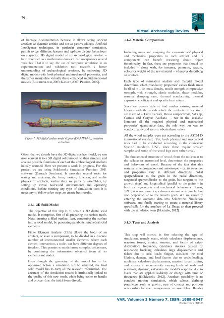
Figure 1. 3D digital surface model of spear (D03-JF88-3), curvature<br />
extraction.<br />
Given that we already have the 3D digital surface model, we can<br />
now convert it to a 3D digital solid model, to then simulate and<br />
analyze possible functions of each of the archaeological artefacts<br />
initially scanned. Here we present a work in progress. For this<br />
project we are using Solidworks Simulation Premium 2011<br />
software (Dassault Systèmes). It provides several tools for<br />
testing and analyzing the form, motion, function, and multiphysics<br />
of artefacts, wether they are parts or assemblies, by<br />
setting up virtual real-world environments and operating<br />
conditions. Before running any type of simulation tests it is<br />
necessary to follow a few steps, to ensure best results.<br />
3.4.1. 3D Solid Model<br />
The objective of this step is to obtain a 3D digital solid<br />
model. It comprises, first of all, preparing the surface mesh.<br />
Next, creating a filled surface. Last, converting the surface<br />
into a solid model, by generating parabolic tetrahedral solid<br />
elements.<br />
Finite Element Analysis (FEA) allows the body of an<br />
artefact, or even a component, to be divided in a discrete<br />
number of interconnected smaller elements, where each<br />
element intersection, a node, can have different degrees of<br />
freedom. This permits to model more complex behaviours,<br />
by combining the information obtained from all its<br />
elements and nodes.<br />
Even though the geometry of the model has to be<br />
optimized before a simulation can be achieved, the final<br />
solid model has to carry all the relevant information. The<br />
accuracy of the simulation results is intrinsically linked to<br />
the quality of this new mesh, while being easier to handle<br />
and process than the initial form directly.<br />
<strong>Virtual</strong> Archaeology Review<br />
3.4.2. Material Composition<br />
Including mass and assigning the raw-materials’ physical<br />
and mechanical properties to each artefact and its<br />
components can benefit reasoning about object<br />
functionality. In fact, these are properties that should be<br />
included – along with, for instance, geometry, texture,<br />
colour or weight of the raw-material – whenever describing<br />
an artefact.<br />
Each type of simulation analysis and material model<br />
determines which mandatory properties’ values fields must<br />
be filled in – i.e. mass density, tensile strength, compressive<br />
strength, yield strength, elastic modulus, shear modulus,<br />
material damping ratio, thermal conductivity, thermal<br />
expansion coefficient and specific heat values.<br />
Since we weren’t able to find neither existing material<br />
libraries with the woods which the artefacts of our study<br />
are made of – Taxus baccata, Buxus sempervirens, Salix sp,<br />
Cornus and Corylus Avellana –, nor in the available<br />
literature all the required physical and mechanical<br />
properties’ quantitative data, the only way out was to<br />
conduct real-world tests to obtain these values.<br />
All the wood samples were cut according to the ASTM D<br />
international standard. Yet, both physical and mechanical<br />
tests had to be conducted according to the equivalent<br />
Spanish standards UNE, since these require smaller<br />
samples and some of the wood logs were rather small.<br />
The fundamental structure of wood, from the molecular to<br />
the cellular or anatomical level, determines the properties<br />
and behaviour of wood. Because of the fact that this<br />
material is heterogeneous and anisotropic – i.e. its structure<br />
and properties vary in different directions: radial<br />
(perpendicular to the grain in the radial direction),<br />
tangential (perpendicular to the grain, but tangent to the<br />
growth rings) and longitudinal (parallel to the grain) – in<br />
both its hygroscopic and mechanical behaviours [Forest,<br />
1999], it is necessary to perform tests not only parallel but<br />
also perpendicular to the wood’s grain. We are currently<br />
entering the outcome data into Solidworks Simulation<br />
software, and finally starting to create a material library<br />
specifically for the artefacts of La Draga to then proceed<br />
with the simulation tests [Moitinho, 2012].<br />
3.4.3. Tests and Analysis<br />
This step will consist in first selecting the type of<br />
simulation, namely static, which calculates displacements,<br />
reaction forces, strains, stresses, and factor of safety<br />
distribution; frequency, calculates stresses caused by<br />
resonance; buckling, calculates large displacements and<br />
failure due to axial loads; fatigue, calculates the total<br />
lifetime, damage, and load factors due to cyclic loading;<br />
nonlinear, calculates displacements, reaction forces, strains,<br />
and stresses at incrementally varying levels of loads and<br />
restraints; dynamic, calculates the model's response due to<br />
loads that are applied suddenly or change with time or<br />
frequency [Solidworks, 2012]. Another possibility is to<br />
conduct motion simulation, which allows defining<br />
parameters such as gravity, type of contact and position<br />
relationship between components or assemblies. Besides<br />
VAR. Volumen 3 Número 7. ISSN: 1989-9947<br />
Diciembre 2012