Instrucciones de Funcionamiento - Maxon Motor
Instrucciones de Funcionamiento - Maxon Motor
Instrucciones de Funcionamiento - Maxon Motor

You also want an ePaper? Increase the reach of your titles
YUMPU automatically turns print PDFs into web optimized ePapers that Google loves.
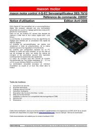
<strong>Instrucciones</strong> <strong>de</strong> <strong>Funcionamiento</strong><br />
maxon motor<br />
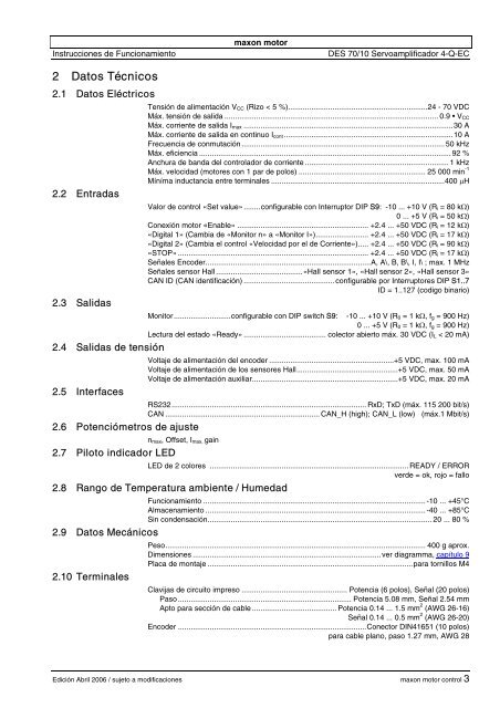
DES 70/10 Servoamplificador 4-Q-EC<br />
2 Datos Técnicos<br />
2.1 Datos Eléctricos<br />
2.2 Entradas<br />
2.3 Salidas<br />
Tensión <strong>de</strong> alimentación V CC (Rizo < 5 %)..................................................................24 - 70 VDC<br />
Máx. tensión <strong>de</strong> salida ..................................................................................................... 0.9 • V CC<br />
Máx. corriente <strong>de</strong> salida I max ...................................................................................................30 A<br />
Máx. corriente <strong>de</strong> salida en continuo I cont ................................................................................10 A<br />
Frecuencia <strong>de</strong> conmutación................................................................................................ 50 kHz<br />
Máx. eficiencia ....................................................................................................................... 92 %<br />
Anchura <strong>de</strong> banda <strong>de</strong>l controlador <strong>de</strong> corriente .................................................................... 1 kHz<br />
Máx. velocidad (motores con 1 par <strong>de</strong> polos) ............................................................ 25 000 min -1<br />
Míníma inductancia entre terminales ..................................................................................400 µH<br />
Valor <strong>de</strong> control «Set value»........configurable con Interruptor DIP S9: -10 ... +10 V (R i = 80 kΩ)<br />
0 ... +5 V (R i = 50 kΩ)<br />
Conexión motor «Enable» .............................................................. +2.4 ... +50 VDC (R i = 12 kΩ)<br />
«Digital 1» (Cambia <strong>de</strong> «Monitor n» a «Monitor I»)......................... +2.4 ... +50 VDC (R i = 17 kΩ)<br />
«Digital 2» (Cambia el control «Velocidad por el <strong>de</strong> Corriente»)..... +2.4 ... +50 VDC (R i = 90 kΩ)<br />
«STOP» .......................................................................................... +2.4 ... +50 VDC (R i = 17 kΩ)<br />
Señales Enco<strong>de</strong>r..............................................................................A, A\, B, B\, I, I\ ; max. 1 MHz<br />
Señales sensor Hall .........................................«Hall sensor 1», «Hall sensor 2», «Hall sensor 3»<br />
CAN ID (CAN i<strong>de</strong>ntificación) ........................................... configurable por Interruptores DIP S1..7<br />
ID = 1..127 (codigo binario)<br />
Monitor...........................configurable con DIP switch S9:<br />
-10 ... +10 V (R 0 = 1 kΩ, f g = 900 Hz)<br />
0 ... +5 V (R 0 = 1 kΩ, f g = 900 Hz)<br />
Lectura <strong>de</strong>l estado «Ready» ....................................... colector abierto máx. 30 VDC (I L < 20 mA)<br />
2.4 Salidas <strong>de</strong> tensión<br />
2.5 Interfaces<br />
Voltaje <strong>de</strong> alimentación <strong>de</strong>l enco<strong>de</strong>r ...........................................................+5 VDC, max. 100 mA<br />
Voltaje <strong>de</strong> alimentación <strong>de</strong> los sensores Hall................................................+5 VDC, max. 50 mA<br />
Voltaje <strong>de</strong> alimentación auxiliar.....................................................................+5 VDC, max. 20 mA<br />
RS232............................................................................................ RxD; TxD (máx. 115 200 bit/s)<br />
CAN ......................................................................... CAN_H (high); CAN_L (low) (máx.1 Mbit/s)<br />
2.6 Potenciómetros <strong>de</strong> ajuste<br />
n max , Offset, I max, gain<br />
2.7 Piloto indicador LED<br />
LED <strong>de</strong> 2 colores .............................................................................................. READY / ERROR<br />
ver<strong>de</strong> = ok, rojo = fallo<br />
2.8 Rango <strong>de</strong> Temperatura ambiente / Humedad<br />
<strong>Funcionamiento</strong> .........................................................................................................-10 ... +45°C<br />
Almacenamiento ........................................................................................................-40 ... +85°C<br />
Sin con<strong>de</strong>nsación.......................................................................................................... 20 ... 80 %<br />
2.9 Datos Mecánicos<br />
2.10 Terminales<br />
Peso........................................................................................................................... 400 g aprox.<br />
Dimensiones .........................................................................................ver diagramma, capítulo 9<br />
Placa <strong>de</strong> montaje .................................................................................................para tornillos M4<br />
Clavijas <strong>de</strong> circuito impreso .................................................. Potencia (6 polos), Señal (20 polos)<br />
Paso .................................................................................. Potencia 5.08 mm, Señal 2.54 mm<br />
Apto para sección <strong>de</strong> cable ........................................ Potencia 0.14 ... 1.5 mm 2 (AWG 26-16)<br />
Señal 0.14 ... 0.5 mm 2 (AWG 26-20)<br />
Enco<strong>de</strong>r .........................................................................................Conector DIN41651 (10 polos)<br />
para cable plano, paso 1.27 mm, AWG 28<br />
Edición Abril 2006 / sujeto a modificaciones maxon motor control 3