Mod. 1035/A1+1 - DOMUSWIRE
Mod. 1035/A1+1 - DOMUSWIRE
Mod. 1035/A1+1 - DOMUSWIRE

Create successful ePaper yourself
Turn your PDF publications into a flip-book with our unique Google optimized e-Paper software.
<strong>Mod</strong>.<br />
<strong>1035</strong>/<strong>A1+1</strong><br />
DS <strong>1035</strong>-007B LBT 87<br />
SISTEMA CITOFONICO A 1+1 FILI<br />
1+1 WIRE HOUSE PHONE SYSTEM<br />
SYSTEME DE PORTIER ELECTRIQUE A 1+1 FILS<br />
SISTEMA DE PORTERO ELECTRICO DE 1+1 HILOS<br />
1+1 DRAHT TÜRSPRECHANLAGE
Impianto esistente con sola chiamata<br />
Existing system with call only<br />
Installation existante avec seul appel<br />
Instalación existente con la sóla llamada<br />
Vorliegende Anlage nur mit Ruf<br />
Impianto a P.E. sistema a 1 + 1 fili<br />
Outdoor set installation with 1+1 system<br />
Installation de portier avec système 1+1<br />
Instalación de portero con sistema 1+1<br />
1+1 Anlage mit Türstation<br />
6<br />
5 6<br />
7<br />
7<br />
1<br />
5 6 7<br />
6<br />
1<br />
7<br />
2<br />
2<br />
3<br />
3<br />
4<br />
4<br />
1. Citofono<br />
House phone<br />
Poste<br />
Teléfono<br />
Hausstation<br />
2. Trasformatore 12 V ~<br />
12 V ~ Transformer<br />
Transformateur 12 V ~<br />
Tranformador 12 V ~<br />
Trafo 12 V ~<br />
3. Pulsantiera<br />
Push button panel<br />
Plaque de rue<br />
Placa de pulsandores<br />
Türstation<br />
4. Serratura elettrica<br />
Electric lock<br />
Serrure électrique<br />
Cerradura eléctrica<br />
Elektrisches Sckloß<br />
5. Tasto apertura serratura<br />
Lock opening key<br />
Touche ouvre-porte<br />
Pulsador abre-puerta<br />
Türöffnertaste<br />
6. Soneria appartamento<br />
Apartment bell<br />
Sonnerie appartement<br />
Timbre vivienda<br />
Etangensummer<br />
7. Tasto chiamata ai piani<br />
Apartment call key<br />
Touche d’appel aux appartements<br />
Pulsador llamada viviendas<br />
Etangenruftaste<br />
2 DS<strong>1035</strong>-007B<br />
DS<strong>1035</strong>-007B 3
ITALIANO<br />
SISTEMA CITOFONICO<br />
CON CHIAMATA ELETTRONICA<br />
A 1+1 FILI<br />
PRESTAZIONI<br />
Il sistema citofonico a 1 + 1 fili URMET <strong>Mod</strong>.<br />
<strong>1035</strong>A/1+1 consente di ottenere il servizio di conversazione,<br />
chiamata, apriporta di un normale impianto<br />
di portiere elettrico con soli 2 fili nella colonna<br />
montante:<br />
1 comune + 1 singolo per ogni apparecchio.<br />
Il portiere elettrico è alimentato con soli due fili da<br />
un trasformatore con tensione di 12V ca.<br />
L’applicazione più interessante del sistema 1 + 1 è<br />
nei vecchi immobili dove è già in funzione l’impianto<br />
di sola chiamata: senza aggiungere altri conduttori<br />
in colonna e negli appartamenti, il servizio esistente<br />
può essere trasformato in servizio di portiere elettrico.<br />
Nel Sistema 1+1 è presente il segreto di conversazione.<br />
A tal fine vengono utilizzati i citofoni speciali <strong>Mod</strong>.<br />
1131 e <strong>Mod</strong>.1132 nell’interno dei quali sono montati<br />
opportuni diodi. Nella pulsantiera occorre inserire<br />
un circuito per ogni pulsante che provvede ad<br />
attivare il segreto di conversazione (montato su<br />
piastrine multiple a 4 circuiti, una ogni 4 pulsanti).<br />
INSTALLAZIONE E COLLEGAMENTO<br />
L’impianto funziona correttamente con una resistenza<br />
di linea totale (andata e ritorno) massima di<br />
12 Ω.<br />
Pertanto occorre usare:<br />
− per distanze ≤ 100 m tra pulsantiera e ultimo<br />
citofono, conduttori di sezione 0,35 mm 2 ;<br />
− per distanze > 100 m, conduttori di sezione ><br />
0,35 mm 2 e tale da garantire una resistenza di<br />
linea non superiore a 12 Ω .<br />
Prevedere i conduttori per l’accensione delle lampadine<br />
della pulsantiera con relativo trasformatore<br />
di potenza adeguata (sino a 2 lampadine si può<br />
utilizzare il trasformatore dell’impianto) ed i conduttori<br />
per l’apertura serratura vicino alla porta.<br />
E’ possibile collegare un massimo di due citofoni in<br />
parallelo.<br />
APPARECCHIATURE<br />
Le apparecchiature necessarie per l’esecuzione<br />
dell’impianto con segreto sono le seguenti:<br />
CITOFONI ∼ Alimentazione 12 V<br />
77 56<br />
∼/1 Massa<br />
3 Chiamata tradizionale su ronzatore<br />
(sistemi con citofoni <strong>Mod</strong>. 1130)<br />
4 Fonia<br />
2 Comando elettroserratura<br />
5 Attivando la serratura elettrica, sul morsetto<br />
5 è presente un impulso negativo della<br />
durata di 500 ms.<br />
PS Chiamata elettronica su altoparlante<br />
SN Inserzione alimentatore video per<br />
impianti videocitofonici.<br />
90<br />
218<br />
<strong>Mod</strong>. 1131<br />
220<br />
69<br />
78,6<br />
25<br />
129<br />
IMPIEGO DELLA GUARNIZIONE ADESIVA SU<br />
P.E. <strong>1035</strong>/67 NELLE APPLICAZIONI CON<br />
PULSANTIERE MOD. 725<br />
FUNZIONE SEGRETO DI CONVERSAZIONE<br />
Per garantire il segreto di conversazione a tutti i<br />
citofoni dell’impianto, nell’interno della pulsantiera<br />
vengono inseriti degli appositi circuiti di segreto<br />
(uno per ogni pulsante).<br />
Tutti i citofoni sono così normalmente disabilitati<br />
alla conversazione (sollevando il microtelefono non<br />
si udrà alcuna conversazione); solo il citofono che<br />
verrà chiamato dall’esterno potrà iniziare la conversazione<br />
con il chiamante, sicuro che nessun altro<br />
utente potrà inserirsi ed intercettare la comunicazione.<br />
Il citofono chiamato rimane abilitato alla conversazione<br />
finchè dalla pulsantiera non viene inviata una<br />
successiva chiamata verso un altro apparecchio.<br />
L’apertura della serratura elettrica è pure abilitata<br />
dal circuito di segreto, ne consegue che non si può<br />
aprire la serratura se non si è stati chiamati.<br />
− Citofoni <strong>Mod</strong>.1131 Sch.1131/35 oppure<br />
Citofoni <strong>Mod</strong>.1132 Sch.1132/35<br />
(entrambi con diodi incorporati);<br />
− Posto esterno Sch.1135/67;<br />
− Pulsantiera Kombi <strong>Mod</strong>. 825;<br />
− Dispositivi segreto per pulsantiera<br />
Kombi<br />
Sch.<strong>1035</strong>/74;<br />
oppure<br />
− Pulsantiera Tradizionale <strong>Mod</strong>. 725;<br />
− Dispositivi segreto per pulsantiera<br />
<strong>Mod</strong>.725<br />
Sch.<strong>1035</strong>/25;<br />
− Trasformatore Sch.9000/20.<br />
<strong>Mod</strong>. 1132<br />
I citofoni <strong>Mod</strong>.1131 e <strong>Mod</strong>.1132 da utilizzare sono<br />
speciali ed hanno rispettivamente Sch.1131/35 e<br />
Sch.1132/35.<br />
La chiamata viene fatta inviando sull’altoparlante<br />
del microfono un tono di chiamata elettronico generato<br />
dal posto esterno.<br />
I citofoni sono inoltre equipaggiati del contatto di<br />
apertura della serratura elettrica (che viene azionato<br />
premendo l’apposito tasto).<br />
POSTO ESTERNO Sch.1135/67<br />
Il posto esterno viene fissato nell’interno dei moduli<br />
doppi.<br />
Sul frontale e sul retro sono accessibili due<br />
potenziometri che consentono la regolazione del<br />
volume esterno (EXT ) e del volume interno (INT ).<br />
Sch. <strong>1035</strong>/67<br />
Sch. <strong>1035</strong>/67<br />
4 DS<strong>1035</strong>-007B<br />
DS<strong>1035</strong>-007B 5
PULSANTIERA <strong>Mod</strong>.KOMBI<br />
Utilizzando le pulsantiere <strong>Mod</strong>. Kombi, occorre inserire<br />
nell’interno le piastrine con segreto<br />
Sch.<strong>1035</strong>/74, che separano i circuiti di chiamata e<br />
di fonia utilizzanti il medesimo conduttore.<br />
Il numero di piastrine occorrenti per le diverse<br />
capacità è indicato nella tabella dell’elenco delle<br />
apparecchiature di fianco alle pulsantiere relative.<br />
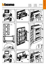
MODULI DOPPI PREDISPOSTI PER P.E.<br />
I moduli doppi sono predisposti per il montaggio del<br />
posto esterno 1 + 1 Sch. <strong>1035</strong>/67 e sono disponibili<br />
in tre versioni:<br />
− con 1 tasto di chiamata e 1 tasto luce scala<br />
− con 2 tasti di chiamata e 1 tasto luce scala<br />
− senza tasti di chiamata e 1 tasto luce scala<br />
PULSANTIERA <strong>Mod</strong>. 725<br />
Utilizzando le pulsantiere tradizionali <strong>Mod</strong>. 725,<br />
occorre inserire nell’interno le piastrine con segreto<br />
Sch.<strong>1035</strong>/25, che separano i circuiti di chiamata e<br />
di fonia utilizzanti il medesimo conduttore.<br />
Il numero di piastrine occorrenti per le diverse<br />
capacità è indicato nella tabella dell’elenco delle<br />
apparecchiature di fianco alle pulsantiere relative.<br />
Importante: Il dispositivo non può essere montato<br />
su pulsantiere con capacità di 1, 2, 3 e 4 pulsanti.<br />
TRASFORMATORE DI SICUREZZA<br />
Sch. 9000/20<br />
75<br />
103<br />
72<br />
Il trasformatore URMET Sch.9000/20 per montaggio<br />
su barra è stato progettato e realizzato in conformità<br />
alle Norme CEI 14-6 II Ed. 1990 relative ai<br />
trasformatori di isolamento e sicurezza.<br />
In quanto tale soddisfa le esigenze di protezione<br />
contro i contatti diretti ed indiretti come richiesto<br />
dalle norme 64-8 relative agli impianti elettrici.<br />
E’ inoltre provvisti del marchio IMQ con relativa<br />
approvazione.<br />
SCHEDE APPARECCHIATURE<br />
Gli apparecchi che compongono il SISTEMA 1+1<br />
sono quindi i seguenti:<br />
− Citofono <strong>Mod</strong>.1131 Bianco<br />
oppure<br />
− Citofono <strong>Mod</strong>.1132 Bianco<br />
− Posto esterno<br />
− Pulsantiera Tradizionale<br />
oppure<br />
− Pulsantiera Kombi<br />
Sch.1131/35<br />
Sch.1132/35<br />
Sch.<strong>1035</strong>/67<br />
<strong>Mod</strong>.725<br />
<strong>Mod</strong>.825<br />
− <strong>Mod</strong>uli doppi Kombi per P.E.:<br />
− con 1 tasto di chiamata e 1 tasto luce scala<br />
Sch.825/15<br />
*Sch.825/315<br />
− con 2 tasti di chiamata e 1 tasto luce scala<br />
Sch.825/16<br />
*Sch.825/316<br />
− senza tasti di chiamata e 1 tasto luce scala<br />
Sch.825/17<br />
*Sch.825/317<br />
Nota: I tipi contrassegnati con asterisco sono nella<br />
versione con frontale verniciato bianco anzichè in<br />
colore alluminio anodizzato naturale.<br />
DISPOSITIVI SEGRETO<br />
Sch.<strong>1035</strong>/74<br />
Per il montaggio nell’interno della Pulsantiera Kombi,<br />
attenersi alle istruzioni allegate ai dispositivi stessi.<br />
DISPOSITIVI SEGRETO<br />
Sch.<strong>1035</strong>/25<br />
41 41<br />
Sch. <strong>1035</strong>/25<br />
Per il montaggio nell’interno della Pulsantiera<br />
<strong>Mod</strong>.725, attenersi alle istruzioni allegate ai<br />
dispositivi stessi.<br />
CARATTERISTICHE ELETTRICHE<br />
- Alimentazione: 11/230 Vca<br />
50/60 Hz<br />
- Potenza: 18 VA<br />
- Secondario: 12 Vca<br />
- Carico massimo:<br />
1,2A alimentando a 110V<br />
1,6A alimentando a 230V<br />
- Protezioni: Con PTC<br />
DIMENSIONI<br />
lunghezza: 126 mm<br />
larghezza: 108 mm<br />
altezza : 75 mm<br />
La lunghezza di 72 mm corrisponde a 4 moduli da<br />
18 mm secondo le norme DIN 43880.<br />
− Dispositivi segreto per pulsantiera<br />
Kombi <strong>Mod</strong>.825<br />
Sch.<strong>1035</strong>/74<br />
oppure<br />
− Dispositivi segreto per pulsantiera<br />
Tradizionale <strong>Mod</strong>.725<br />
Sch.<strong>1035</strong>/25<br />
− Trasformatore<br />
Accessori<br />
Sch.9000/20<br />
− Confezione trasformazione tavolo per<br />
citofono <strong>Mod</strong>.1131<br />
Sch.1130/12<br />
− Confezione trasformazione tavolo per<br />
citofono <strong>Mod</strong>.1132<br />
Sch.1132/50<br />
6 DS<strong>1035</strong>-007B<br />
DS<strong>1035</strong>-007B 7
ENGLISH<br />
1+1 WIRE HOUSE PHONE SYSTEM<br />
PROGRAMMING<br />
URMET 1+1 wire system <strong>Mod</strong>.<strong>1035</strong>A/1+1 allows to<br />
obtain the service of a standard outdoor se<br />
installation with conversation, call, electric loch<br />
opening, with only 2 wires in the rising column: 1<br />
common + 1 for each house phone. The outdoor set<br />
is fed, with two wires only, by a 12 V a.c. voltage<br />
transformer.<br />
The most interesting application of the 1+1 system<br />
is in old buildings where only the call facility exists:<br />
without adding any further wires in the cable conduit<br />
and in the appartments, the existing service can be<br />
transformed into an outdoor set installation.<br />
The 1 + 1 wire electronic house phone system<br />
allows to obtain the secrecy of conversation.<br />
For this purpose the special house phones <strong>Mod</strong>.<br />
1131 and <strong>Mod</strong>. 1132, already equipped with the<br />
proper diodes, have to be installed, while in the<br />
push button panel a circuit for each key (mounted<br />
onto multiple plates with 4 diodes for each 4 keys)<br />
has to be inserted.<br />
INSTALLATION AND CONNECTION<br />
The system works correctly with a maximum total<br />
(forwards and backwards) line resistance of 12<br />
Ohms.<br />
It is therefore necessary to use:<br />
− for distances ≤ 100 m beetween push button<br />
panel and the farthest house phone, wires with<br />
section 0,35 mm 2<br />
− for distances > 100 m, wires with section > 0,35<br />
mm 2 and such as to guarantee a line resistance<br />
not higher than 12 Ohms<br />
It is necessary to foresee the wires for push button<br />
panel lamps lighting with the related adequate power<br />
transformer (for up to 2 lamps the standard system<br />
transformer can be used) as well as the wires for the<br />
lock opening next to te door.<br />
It is no possible to connect more than 2 house<br />
phones in parallel.<br />
HOUSE PHONES<br />
77 56<br />
218<br />
<strong>Mod</strong>. 1131<br />
90<br />
220<br />
69<br />
∼ supply 12 V<br />
∼/1 ground<br />
3 traditional call with buzzer<br />
(systems with house phone <strong>Mod</strong>. 1130)<br />
4 sound<br />
2 electric lock control<br />
5 when the electric lock is activated,on terminal<br />
5 there is a negative<br />
impulse which lasts for 500 ms<br />
PS electronic call on loudspeaker<br />
SN insertion of video power supply in video<br />
house phone installations.<br />
78,6<br />
25<br />
129<br />
SECRECY OF CONVERSATION<br />
To assure the secrecy to all the house phones,<br />
special devices for secrecy of conversation are<br />
inserted into the push button panel (one for each<br />
key).<br />
So, all the house phones will be cut off from any<br />
converation (nothing can be heard when picking up<br />
the handset); only the called house phone can start<br />
a conversation with the calter, no other being able<br />
to intercept the call. The called house phone is<br />
qualified to talk until another call is made from the<br />
push button panel to another house phone.<br />
The electric lock opening depends from circuit of<br />
secrecy of conversation (the lock cannot be operated<br />
unless the house phone has been called).<br />
EQUIPMENT<br />
The items required for this system are the following<br />
ones:<br />
− House phone <strong>Mod</strong>.1131 Ref.1131/35<br />
or<br />
− House phone <strong>Mod</strong>.1132 Ref.1132/35<br />
(both with diode plate inserted)<br />
− Loudspeaking unit Ref.<strong>1035</strong>/67<br />
− Kombi push button panel <strong>Mod</strong>.825<br />
− Secrecy of conversation device for<br />
Kombi push button panel Ref.<strong>1035</strong>/74<br />
or<br />
− Traditional push button panel Ref.725<br />
− Secrecy of conversation device for<br />
push button panel mod.725 Ref.<strong>1035</strong>/25<br />
− Transformer Ref.9000/20.<br />
<strong>Mod</strong>. 1132<br />
Use special house phones <strong>Mod</strong>. 1131 Ref. 1131/35<br />
and <strong>Mod</strong>. 1132 Ref. 1132/35.<br />
The call is possible by sending to the microphone<br />
loudspeaker an electronic call tone produced by the<br />
loudspeaking unit.<br />
The house phone is also equipped with an electric<br />
lock opening (operating by pressing the proper<br />
key).<br />
USE OF THE ADHESIVE SEAL ON THE <strong>1035</strong>/67<br />
LOUDSPEAKING UNIT IN APPLICATIONS ON<br />
MOD. 725 PUSH BUTTON PANELS<br />
Sch. <strong>1035</strong>/67<br />
LOUDSPEAKING UNIT Ref. <strong>1035</strong>/67<br />
The loudspeaking unit is placed inside double<br />
modules.<br />
On the front panel and the back there are two<br />
accessible potentiometers that allow adjustment of<br />
the external volume (EXT) and the internal volume<br />
(INT).<br />
Sch. <strong>1035</strong>/67<br />
8 DS<strong>1035</strong>-007B<br />
DS<strong>1035</strong>-007B 9
KOMBI PUSH BUTTON PANEL<br />
Use Kombi push button panel inserting the diode<br />
plates with secrecy Ref. <strong>1035</strong>/74, that separate the<br />
call and sound circuits that use the same wire.<br />
For different capacities, the required number of<br />
diode plates is indicated in the equipment table list<br />
near the respective push button panels.<br />
DOUBLE MODULES ARRANGED FOR<br />
LOUDSPEAKING UNIT<br />
The double modules are necessary when the 1+1<br />
wire loudspeaking unit Ref. <strong>1035</strong>/67 has to be<br />
installed, and are available in the following three<br />
versions:<br />
− with 1 call key and 1 stair lamp key<br />
− with 2 call keys and 1 stair lamp key<br />
− without call key and 1 stair lamp key<br />
SECRECY DEVICE REF. <strong>1035</strong>/74<br />
PUSH BUTTON PANEL <strong>Mod</strong>. 725<br />
Use traditional push button panel mod. 725 inserting<br />
diode plates with secrecy Ref. <strong>1035</strong>/25 that separate<br />
the call and sound circuits using the same wire.<br />
For different capacities the required number of<br />
diode plates is indicated in the equipment list near<br />
the respective push button panels.<br />
Important : The device cannot be installed in push<br />
buttons panels with 1, 2, 3 or 4 buttons.<br />
SECRECY DEVICE REF. <strong>1035</strong>/25<br />
41 41<br />
Sch. <strong>1035</strong>/25<br />
Use relative instructions to install secrecy device on<br />
<strong>Mod</strong>.725 push button panel.<br />
TRANSFORMER<br />
Ref.9000/20<br />
75<br />
103<br />
The URMET transformer Ref.9000/20 for bar<br />
mounting version has been designed and made in<br />
conformity with the existing rules.<br />
ELECTRICAL FEATURES<br />
- Supply voltage : 110/230 Vca<br />
50/60 Hz<br />
- Power: 18 VA<br />
- Output voltage: 12 Vac<br />
- Maximum load:<br />
1,2 A supplying 110 V<br />
1,6 A supplying 230 V<br />
- Protections: by PTC<br />
DIMENSIONS<br />
- length: 126 mm<br />
- width: 108 mm<br />
- height: 75 mm<br />
72<br />
The length of 72 mm corresponds to 4 modules of<br />
18 mm each, in accordance to DIN 43880 rules.<br />
EQUIPMENT<br />
1+1 wire SYSTEM is composed by the following<br />
items:<br />
− white house phone <strong>Mod</strong>.1131<br />
or<br />
− white house phone <strong>Mod</strong>. 1132<br />
− loudspeaking unit<br />
Ref.1131/35<br />
Ref.1132/35<br />
Ref.<strong>1035</strong>/67<br />
− traditional push button panel <strong>Mod</strong>.725<br />
or<br />
- Kombi push button panel <strong>Mod</strong>.825<br />
− Kombi double modules for loudspeaking unit:<br />
− with 1 call key and 1 stair lamp key<br />
Ref. 825/15<br />
*Ref. 825/315<br />
− with 2 call keys and 1 stair lamp key<br />
Ref. 825/16<br />
*Ref. 825/316<br />
− without call keys and 1 stair lamp key<br />
Ref. 825/17<br />
*Ref. 825/317<br />
Note : References bearing the symbol * concern<br />
panels with white front plate instead of aluminum.<br />
− secrecy device for push button panel<br />
Kombi mod. 825 Ref. <strong>1035</strong>/74<br />
or<br />
− secrecy device for traditional push button panel<br />
<strong>Mod</strong>.725 Ref. <strong>1035</strong>/25<br />
− transformer Ref. 9000/20<br />
Accessories<br />
− Table mounting kit for house phone<br />
mod. 1131 Ref. 1130/12<br />
− Table mounting kit for house phone<br />
mod. 1132 Ref. 1132/50<br />
Use relative instructions to install secrecy device on<br />
Kombi push button panel.<br />
10 DS<strong>1035</strong>-007B<br />
DS<strong>1035</strong>-007B 11
FRANÇAIS<br />
SYSTEME DE PORTIER<br />
ELECTRIQUE A 1+1 FILS<br />
PERFORMANCES<br />
Le système URMET à 1+1 fils <strong>Mod</strong>.<strong>1035</strong>A/1+1<br />
permet de réaliser une installation de portier<br />
électrique standard avec conversation, appel, ouverture<br />
de serrure électrique avec deux fils<br />
seulement dans la colonne montante: 1 commun +<br />
1 pour chaque poste.<br />
Le portier électrique est alimenté avec deux fils<br />
seulement, à l’aide d’un transformateur tension<br />
12 V ∼.<br />
L’application la plus intéressante du système 1+1<br />
est dans les ancies immeubles où le service sonnerie<br />
est déjà installé: sans ajouter d’autres conducteurs<br />
ni dans les colonnes ni dans les appartements, le<br />
service existant peut être transformé en une<br />
installation de portier électrique.<br />
Le système à 1+1 fils permet d’utiliser le secret de<br />
conversation.<br />
A ce propos il faut utiliser les postes d’appartement<br />
spéciaux <strong>Mod</strong>. 1131 et <strong>Mod</strong>. 1132, déjà équipés<br />
avec les diodes prévues à cet effet, tandis que dans<br />
la plaque de rue il faut installer un circuit pour<br />
chaque bouton (fixé sur des plaques multiples à 4<br />
diodes tous les 4 boutons), permettant ainsi le<br />
secret de conversation.<br />
INSTALLATION ET BRANCHEMENT<br />
Le système fonctionne correctement avec une<br />
résistance de ligne totale (aller et retour) de 12<br />
Ohms max.<br />
Par conséquent il faut employer:<br />
− pour des distances ≤100 m entre plaque de rue<br />
et le dernier poste, des fils section 0,35 mm 2<br />
− pour des distances > 100 m, des fils > 0,35 mm 2<br />
qui puissent assurer une résistance de ligne non<br />
supérieure à 12 Ohms<br />
Il faut prévoir les conducteurs pour l’allumage des<br />
lampes de la plaque de rue avec le relatif<br />
transformateur de puissance adéquate (jusqu’à 2<br />
lampes l’on peut utiliser le transformateur de<br />
l’installation) et les conducteurs pour l’ouverture de<br />
la serrure à côte de la porte.<br />
2 postes d’appartement max. peuvent être installés<br />
en parallèle.<br />
EQUIPMENT<br />
POSTES D’APPARTEMENT<br />
77 56<br />
218<br />
<strong>Mod</strong>. 1131<br />
90<br />
220<br />
69<br />
∼ alimentation 12 V<br />
∼/1 masse<br />
3 appel traditionnel avec ronfleur<br />
(installation avec poste d’appartement<br />
<strong>Mod</strong>. 1130)<br />
4 phonie<br />
2 mise en activité de la serrure électrique<br />
5 en activant la serrure électrique sur<br />
la borne 5 il y a une arrivée de<br />
courantnégatif dont la durée est 500 ms<br />
PS appel électronique sur haut-parleur<br />
SN insertion alimentation vidéo<br />
pour installations de vidéo-portier<br />
78,6<br />
25<br />
129<br />
EMPLOI DU JOINT ADHESIF SUR LE POSTE<br />
EXTERNE <strong>1035</strong>/67 POUR LES APPLICATIONS<br />
AVEC LES PLAQUES DE RUE MOD. 725<br />
FONCTION DU SECRET DE CONVERSATION<br />
Le secret de conversation à tous les postes de<br />
installation portier électrique est assuré par des<br />
circuits de secret fait exprès qui sont insérés dans<br />
la plaque de rue (un pour chaque touche).<br />
De cette façon tout poste est exclus de la<br />
conversation (en soulevant le micro l’on entend<br />
rien); se serait seulement le poste qui sera appelé<br />
de l’extérieur qui pourra commencer la conversation<br />
avec celui qui appelle, sûr que personne-parmi les<br />
usagers-pourra s’insérér et intercepter la<br />
communication.<br />
Le poste appelé reste habilité á la conversation<br />
jusq’au moment de la plaque de rue l’on envoie un<br />
autre appel vers un autre appareil.<br />
Le circuit du secret habilite aussi l’ouverture serrure<br />
électrique: par conséquent l’on ne peut pas ouvrir la<br />
serrure si l’on n’a pas été appelés.<br />
Les équipments nécessaires pour l’installation avec<br />
secret de conversation sont:<br />
− postes d’appartement <strong>Mod</strong>.1131 Réf. 1131/35<br />
ou<br />
− postes d’appartement <strong>Mod</strong>.1132 Réf.1132/35<br />
(les deux avec plaque à diodes insérée)<br />
− micro-HP Réf.<strong>1035</strong>/67<br />
− plaque de rue Kombi <strong>Mod</strong>.825<br />
− secret de conversation pour<br />
plaque Kombi Réf.<strong>1035</strong>/74<br />
ou<br />
− plaque de rue traditionnelle <strong>Mod</strong>.725<br />
− secret de conversation pour<br />
plaque <strong>Mod</strong>.725 Réf.<strong>1035</strong>/25<br />
− transformateur Réf. 9000/20<br />
<strong>Mod</strong>. 1132<br />
On utilise les postes d’appartement spéciaux <strong>Mod</strong>.<br />
1131 Réf. 1131/35 et <strong>Mod</strong>. 1132 Réf. 1132/35.<br />
L’appel se produit en envoyant sur l’haut-parleur du<br />
micro un ton d’appel électronique produit du<br />
micro-HP.<br />
Les postes sont aussi équipés du contact pour<br />
l’ouverture de la serrure électrique (en appuyant<br />
sur la touche prévue à cet effet).<br />
MICRO-HP Réf. <strong>1035</strong>/67<br />
Le micro-HP est fixé à l’intérieure des modules<br />
doubles.<br />
De front et derrière l’on peut joindre 2 potentiomètres<br />
permettant le réglage du volume extérieur (EXT) et<br />
l’intérieur (INT).<br />
Sch. <strong>1035</strong>/67<br />
Sch. <strong>1035</strong>/67<br />
12 DS<strong>1035</strong>-007B<br />
DS<strong>1035</strong>-007B 13
PLAQUE DE RUE KOMBI<br />
L’on utilise les plaques de rue <strong>Mod</strong>. Kombi en<br />
insérant à l’intérieur les plaques avec secret qui<br />
séparent les circuits d’appel et de phonie en utilisant<br />
le même conducteur.<br />
Le nombre des plaques nécessaires pour le<br />
différents types de plaque de rue est indiqué dans<br />
la table.<br />
MODULES DOUBLES PRÉDISPOSÉS POUR<br />
MICRO-HP<br />
PLAQUE DE RUE <strong>Mod</strong>. 725<br />
L’on utilise les plaques de rue traditionnelles<br />
<strong>Mod</strong>. 725 en insérant à l’intérieur les plaques avec<br />
secret Réf. <strong>1035</strong>/25, qui séparent les circuits d’appel<br />
et de phonie en utilisant le même conducteur.<br />
Le nombre des plaques nécessaires pour les<br />
différents types de plaque de rue est indiqué dans<br />
la table.<br />
Important : Le dispositif ne peut pas être installé<br />
dans plaques de rue à 1, 2, 3 ou 4 boutons.<br />
TRANSFORMATEUR<br />
RÉF. 9000/20<br />
75<br />
ÉQUIPMENTS<br />
Les équipments nécessaires pour l’installation du<br />
système de portier électrique à 1+1 fils sont les<br />
suivants:<br />
− poste d’appartement <strong>Mod</strong>.1131 blanc<br />
Réf.1131/35<br />
ou<br />
− poste d’appartement <strong>Mod</strong>.1132 blanc<br />
Réf.1132/35<br />
− micro-HP<br />
Réf.<strong>1035</strong>/67<br />
103<br />
72<br />
− plaque de rue traditionnelle<br />
ou<br />
− plaque de rue Kombi<br />
<strong>Mod</strong>.725<br />
<strong>Mod</strong>.825<br />
Les modules doubles sont nécessaires à<br />
l’installation du micro-HP 1+1 fils Réf. <strong>1035</strong>/67 et<br />
sont disponibles comme il suit:<br />
− avec 1 touche d’appel et 1 touche éclairage<br />
escaliers<br />
− avec 2 touches d’appel et 1 touche éclairage<br />
escaliers<br />
− sans touches d’appel et 1 touche éclairage<br />
escaliers<br />
SECRET DE CONVERSATION RÉF. <strong>1035</strong>/74<br />
SECRET DE CONVERSATION RÉF. <strong>1035</strong>/25<br />
41 41<br />
Sch. <strong>1035</strong>/25<br />
Le transformateur Urmet Réf.9000/20 pour montage<br />
sur barre a été projeté et realisé confermément aux<br />
normes en viguer.<br />
CARACTÉRISTIQUES ÉLECTRIQUES<br />
- tension d’alimentation: 110/230 Vca<br />
50/60 Hz<br />
- puissance: 18 Va<br />
- secondaire: 12 Vca<br />
- charge maximum:<br />
1,25 A avec 110 V alimentation<br />
1,6 A avec 230 V alimentation<br />
- protections: avec PTC<br />
DIMENSIONS:<br />
- longueur: 126 mm<br />
- largeur: 108 mm<br />
- hauteur: 75 mm<br />
− modules doubles Kombi pour micro-HP:<br />
− avec 1 touche d’appel et 1 touche éclairage<br />
escaliers<br />
Réf.825/15<br />
*Réf.825/315<br />
− avec 2 touches d’appel et 1 touche éclairage<br />
escaliers<br />
Réf.825/16<br />
*Réf.825/316<br />
− sans touches d’appel et 1 touche éclairage<br />
escaliers<br />
Réf.825/17<br />
*Réf.825/317<br />
Note: Les Réferences marquées avec * sont en<br />
version avec plaque frontale coloris blanc au lieu de<br />
aluminium anodisé.<br />
− dispositif secret pour plaque de rue<br />
Kombi <strong>Mod</strong>. 825<br />
Réf.<strong>1035</strong>/74<br />
ou<br />
− dispositif secret pour plaque de rue<br />
traditionnelle <strong>Mod</strong>. 725 Réf.<strong>1035</strong>/25<br />
− transformateur<br />
Réf.9000/20<br />
La longueur correspond à 4 modules de 18 mm<br />
suivant les normes DIN 43880.<br />
Accessoires<br />
Pour l’installation à l’intérieur de la plaque de rue<br />
<strong>Mod</strong>.725, il faut suivre les instructions relatives.<br />
− confection pour version de table pour poste<br />
d’appartement <strong>Mod</strong>.1131 Réf.1130/12<br />
− confection pour version de table pour poste<br />
d’appartement <strong>Mod</strong>.1132 Réf.1132/50<br />
Pour l’installation à l’intérieur de la plaque de rue<br />
Kombi, il faut suivre les instructions relatives.<br />
14 DS<strong>1035</strong>-007B<br />
DS<strong>1035</strong>-007B 15
ESPAÑOL<br />
SISTEMA DE PORTERO ELECTRICO<br />
DE 1+1 HILOS<br />
PRESTACIONES<br />
El sistema de portero eléctrico URMET de 1+1 hilos<br />
<strong>Mod</strong>.<strong>1035</strong>A/1+1 permite de realizzar el servicio de<br />
conversación, llamada, abre-puerta tal como una<br />
normal installación de portero eléctrico con sólo 2<br />
hilos en la columna: 1 común + 1 individual por cada<br />
teléfono.<br />
El portero eléctrico se elimina con dos hilos solamente<br />
por medio de un transformador con voltaje<br />
de 12 V ~.<br />
El empleo más interesante del sistema 1+1 es para<br />
los viejos edificios en los que ya se encuentra el<br />
servicio de llamada: sin añadir otros hilos en la<br />
columna y en las viviendas, el servicio de llamada<br />
se puede transformar en servicio de portero<br />
eléctrico.<br />
INSTALACION Y CONEXION<br />
La instalación funciona correctamente con una<br />
resistencia de linea total (ida y vuelta) maxima 12Û.<br />
Por lo tanto hay que emplear:<br />
− para distancias ≤ 100 m entre placa de pulsadores<br />
y último teléfono, hilos de sección 0,35 mm 2 ;<br />
− para distancias > 100 m, hilos de sección<br />
> 0,35 mm 2 y que garantizan una resistencia de<br />
linea no superior a los 12 Ω.<br />
Hay que proveer los conductores y el transformador<br />
de potencia conveniente para el alumbrado de la<br />
placa de pulsadores (hasta 2 lámparas se puedee<br />
emplear el transformador del sistema); proveer<br />
también los conductores para el accionamiento de<br />
la cerradura cerca de la puerta.<br />
TELÉFONOS<br />
77 56<br />
218<br />
<strong>Mod</strong>. 1131<br />
90<br />
69<br />
∼ Alimentación 12 V<br />
∼/1 Masa<br />
3 Llamada tradicional en zumbador<br />
(sistemas con Teléfonos <strong>Mod</strong>. 1130)<br />
4 Fonía<br />
2 Mando cerradura eléctrica<br />
5 Activando la cerradura eléctrica,<br />
en el borne 5 se encuentra un impulso<br />
negativo de 500 ms. de duración<br />
PS Llamada electrónica a altavoz<br />
SN Incorporación de alimentador de vídeo<br />
para sistemas de portero eléctrico.<br />
78,6<br />
129<br />
El sistema 1 + 1 tiene secreto de conversación.<br />
Para ello se utilizan los teléfonos especiales <strong>Mod</strong>.<br />
1131 y <strong>Mod</strong>. 1132 dentro de los cuales se montan<br />
diodos específicos. En la placa de pulsadores es<br />
necesario introducir un circuito para cada pulsador<br />
que se encarga de activar el secreto de conversación<br />
(montado en placas múltiples de 4 circuitos, una<br />
por cada 4 pulsadores).<br />
FUNCION SECRETO DE CONVERSACION<br />
Se pueden conectar dos teléfonos en paralelo<br />
como máximo.<br />
EQUIPOS<br />
Los equipos necesarios para la ejecución del sistema<br />
con secreto son los siguientes.<br />
220<br />
25<br />
USO DE LA JUNTA ADHESIVA EN EL<br />
MICROALTAVOZ <strong>1035</strong>/67 EN LAS APLICACIONES<br />
CON PLACA DE PULSADORES MOD. 725<br />
Para garantizar el secreto de conversación a todos<br />
los teléfonos del sistema del portero eléctrico, en el<br />
interior de la placa pulsadora se insertan apropiados<br />
circuitos de segreto (uno cada pulsador).<br />
De esta manera todos los teléfonos están excluidos<br />
normalmente de la conversación (levantando el<br />
microteléfono no se oye ninguna conversación);<br />
solo el teléfono que será llamado por el exterior<br />
podrá empezar la conversación con quien llama,<br />
seguro que ningún otro usuario podrá insertarse a<br />
interceptar la comunicación.<br />
El teléfono llamado está habilitado a la conversación<br />
hasta cuando de la placa pulsadora no llega la<br />
llamada sucesiva hacia otro aparato.<br />
La abertura de la cerradura eléctrica también está<br />
habilitada por el circuito de secreto, por eso el<br />
usuario no puede abrir la cerradura si no ha sido<br />
llamado.<br />
− Teléfonos <strong>Mod</strong>.1131 Ref.1131/35<br />
o<br />
teléfonos <strong>Mod</strong>.1132 Ref.1132/35<br />
(ambos con diodos incorporados);.<br />
− Microaltavoz Ref.<strong>1035</strong>/67;<br />
− Placa de pulsadores Kombi <strong>Mod</strong>.825;<br />
− Dispositivos de secreto para placa de<br />
pulsadores Kombi Ref.<strong>1035</strong>/74;<br />
o<br />
− Placa de pulsadores Tradicional <strong>Mod</strong>.725;<br />
− Dispositivos de secreto para placa de<br />
pulsadores <strong>Mod</strong>.725 Ref.<strong>1035</strong>/25;<br />
− Transformador Ref.9000/20.<br />
<strong>Mod</strong>. 1132<br />
Los teléfonos <strong>Mod</strong>. 1131 y <strong>Mod</strong>. 1132 que se<br />
utilizan son especiales y son Ref. 1131/35 y Ref.<br />
1132/35 respectivamente.<br />
La llamada se hace enviando al altavoz del<br />
micrófono un tono de llamada electrónico producido<br />
desde el microaltavoz.<br />
Asimismo, los teléfonos son equipados por el<br />
contacto de apertura de la cerradura eléctrica (que<br />
se acciona pulsando la tecla específica).<br />
MICROALTAVOZ Ref. <strong>1035</strong>/67<br />
El microaltavoz se fija dentro de los módulos dobles.<br />
En el frontal y en el dorso se accede a dos<br />
potenciómetros que permiten regular el volumen<br />
exterior (EXT) y el volumen interior (INT).<br />
Sch. <strong>1035</strong>/67<br />
Sch. <strong>1035</strong>/67<br />
16 DS<strong>1035</strong>-007B<br />
DS<strong>1035</strong>-007B 17
PLACA DE PULSADORES <strong>Mod</strong>. KOMBI<br />
Utilizando las placas de pulsadores <strong>Mod</strong>. Kombi, es<br />
necesario introducir en el interior las placas de<br />
secreto Ref. <strong>1035</strong>/74, que separan los circuitos de<br />
llamada y de fonía que utilizan el mismo conductor.<br />
El número de placas necesarias para las distintas<br />
capacidades se indica en la tabla de la lista de los<br />
equipos al lado de las placas de pulsadores<br />
correspondientes.<br />
MODULOS DOBLES PREPARADOS PARA<br />
MICROALTAVOZ<br />
PLACA DE PULSADORES <strong>Mod</strong>. 725<br />
Utilizando las placas de pulsadores tradicionales<br />
<strong>Mod</strong>. 725, es necesario introducir dentro las placas<br />
de secreto Ref. <strong>1035</strong>/25, que separan los circuitos<br />
de llamada y de fonía que utilizan el mismo<br />
conductor.<br />
El número de placas necesarias para las diferentes<br />
capacidades se indica en la tabla de la lista de los<br />
equipos junto a las placas de pulsadores<br />
correspondientes.<br />
Importante : El dispositivo no puede mortarse en<br />
placas pulsadoras con capacidad de 1, 2, 3 y 4<br />
pulsadores.<br />
TRANSFORMADOR DE SEGURIDAD<br />
Ref. 9000/20<br />
75<br />
103<br />
72<br />
El transformador URMET Ref.9000/20 para el<br />
montaje en barra se ha diseñado y realizado según<br />
las normas vigentes.<br />
REF. DE LOS EQUIPOS<br />
Por lo tanto, los equipos que componen el SISTE-<br />
MA 1 + 1 son los siguientes:<br />
− Telefono <strong>Mod</strong>. 1131 Blanco<br />
o<br />
− Telefono <strong>Mod</strong>. 1032 Blanco<br />
− Microaltavoz<br />
Ref.1131/35<br />
Ref.1132/35<br />
Ref.<strong>1035</strong>/67<br />
− Placa de pulsadores Tradicional <strong>Mod</strong>.725<br />
o<br />
− Placa de pulsadores Kombi <strong>Mod</strong>.825<br />
− Módulos dobles Kombi para microaltavoz.:<br />
− con 1 tecla de llamada y 1 tecla para luz de<br />
escalera Ref. 825/15<br />
*Ref. 825/315<br />
− con 2 teclas de llamada y 1 tecla para luz de<br />
escalera Ref. 825/16<br />
*Ref. 825/316<br />
− sin teclas de llamada y 1 tecla para luz de<br />
escalera Ref. 825/17<br />
*Ref. 825/317<br />
Los módulos dobles están preparados para montar<br />
el microaltavoz 1 + 1 Ref. <strong>1035</strong>/67<br />
y se ofrecen en tres versiones:<br />
- con 1 tecla de llamada y 1 tecla para la luz<br />
de la escalera<br />
- con 2 teclas de llamada y 1 tecla para la luz<br />
de la escalera<br />
- sin teclas de llamada y 1 tecla para la luz<br />
de la escalera<br />
DISPOSITIVOS DE SECRETO<br />
Ref. <strong>1035</strong>/74<br />
DISPOSITIVOS DE SECRETO<br />
Ref.<strong>1035</strong>/25<br />
41 41<br />
Sch. <strong>1035</strong>/25<br />
CARACTERISTICAS ELÉCTRICAS<br />
− Alimentación:<br />
− Potencia:<br />
− Secundario;<br />
− Carga máxima:<br />
− Protecciones:<br />
DIMENSIONES<br />
110/230 Vca<br />
50/60 Hz<br />
18 VA<br />
12 Vca<br />
- longitud: 126 mm<br />
- anchura: 108 mm<br />
- altura: 75 mm<br />
1.2 A alimentando a 110V<br />
1.6A alimentando a 230V<br />
Con PTC<br />
Nota: los tipos marcados con asterisco son de la<br />
versión con frontal pintado de color blanco en vez<br />
de color de aluminio anodizado natural.<br />
− Dispositivos de secreto para placa de<br />
pulsadores Kombi <strong>Mod</strong>. 825 Ref.<strong>1035</strong>/74<br />
o<br />
− Dispositivos de secreto para placa de<br />
pulsadores Tradicional <strong>Mod</strong>.725 Ref.<strong>1035</strong>/25<br />
− Transformador<br />
Accesorios<br />
Ref.9000/20<br />
− Kit de transformación mesa para teléfono<br />
<strong>Mod</strong>.1131 Ref. 1130/12<br />
Para el montaje dentro de la Placa de pulsadores<br />
<strong>Mod</strong>.725, seguir las instrucciones adjuntas a los<br />
dispositivos.<br />
La longitud de 72 mm corresponde a 4 módulos de<br />
18 mm según las normas DIN 43880.<br />
− Kit de transformación mesa para teléfono<br />
<strong>Mod</strong>.1132 Ref. 1132/50<br />
Para el montaje dentro de la Placa de pulsadores<br />
Kombi, seguir las instrucciones adjuntas a los<br />
dispositivos.<br />
18 DS<strong>1035</strong>-007B<br />
DS<strong>1035</strong>-007B 19
DEUTSCH<br />
1+1 DRAHT TÜRSPRECHANLAGE<br />
FUNKTIONEN<br />
Mit der URMET 1+1-Draht-Türsprechanlage<br />
<strong>Mod</strong>.<strong>1035</strong>A/1+1 erhält man die Sprech-,Rufund<br />
Türöffnungsanlage einer normalen Türstation mit<br />
nur 2 Drähten in der Steigleitung: 1 gemeinsame<br />
Leitung und 1 Einzelleitung für jede Wohnung.<br />
Die Türstation wird mit nur 2 Drähten von einem<br />
12 V ~ Spannungstrafo gespeist.<br />
Die interessanteste Verwendungsart des 1+1<br />
Systems erhalten wir bei Albauten, wo bereits eine<br />
Rufanlage in Betrieb ist: ohne weitere Leiter in der<br />
Steigleitung und in den Wohnungen zu installieren,<br />
kann die bestehende Anlage in eine Türstation<br />
umgewandelt werden.<br />
Mit der 1+1-Draht-Türsprechanlage erhält man die<br />
Abhörsicherheit; um das herzustellen, werden die<br />
speziellen Haustelefone <strong>Mod</strong>. 1131 und <strong>Mod</strong>. 1132<br />
verwendet, die mit einer Diodenplatine ausgerüstet<br />
sind.<br />
Eine Verbindung für jede Taste muß dagegen in die<br />
Türstation eingebaut werden (montiert auf<br />
Mehrfachplatinen mit 4 Leitungen für jeweils 4<br />
Tasten).<br />
INSTALLIERUNG UND ANSCHLUSS<br />
Die Anlage funktioniert fehlerfrei bei einem<br />
maximalen Gesamtleitungswiderstand (Hin- und<br />
Rückleitung) von 12 Ohm.<br />
Deshalb sind folgende Dimensionen zu verwenden:<br />
− für Entfernungen ≤ 100 m zwischen der Türstation<br />
und dem am weitesten entfernt liegenden<br />
Haustelefon, Drähte mit 0,35 mm 2 Durchmesser<br />
− für Entfernungen > 100 m., Drähte mit einem<br />
Durchmesser >0,35 mm 2 , und um einen<br />
Leitungswiderstand zu gewährleisten, der nicht<br />
mehr als 12 Ohm beträgt.<br />
Die Lefter zum Anzünden der Türstation-lampen<br />
mit einem angemessenen Trafo versehen (bei bis<br />
zu 2 Lampen kann der Anlagentrafo verwendet<br />
verden) und die Türöffnungsleiter in Türnähe<br />
anbringen.<br />
Man kann max. 2 Haustelefone parallelschalten.<br />
GRUNDAUSSTATTUNG<br />
HAUSTELEFONE<br />
77 56<br />
90<br />
218<br />
<strong>Mod</strong>. 1131<br />
220<br />
69<br />
∼ Speisung<br />
∼/1 Erdung<br />
3 Herkömmlicher Ruf mit Summer<br />
(Anlage mit Haustelefonen <strong>Mod</strong>.1130)<br />
4 Ton<br />
2 Kontrolle des elektrischen Schlosses<br />
5 Wenn der elektrische Türöffner<br />
aktiviert ist, gibt es auf der<br />
Anschlußklemme 5 einen negativen<br />
Impuls, der 500 ms lang dauert.<br />
PS Elektronischer Ruf am Lautsprecher<br />
SN Einbau eines Videonetzgerätes<br />
bei Videohaussprechanlagen<br />
78,6<br />
25<br />
129<br />
ABHÖRSPERRE<br />
Um die Mithörsperre für alle Hausstationen der<br />
Türsprechanlagen zu gewährleisten, werden im<br />
Innern der Türstation entsprechende Mithörsperre-<br />
Kreise (einer für jede Taste) installiert.<br />
Somit sind alle anderen Hausstationen vom<br />
Gespräch ausgeschlossen (wenn man den Hörer<br />
abnimmt, hört man Kein Gespräch), und nur die<br />
Hausstation kann das Gespräch einleiten, die von<br />
außen angerufen wurde. Somit hat man die Gewähr,<br />
daß sich kein anderer Teilnehmer in die Leitung<br />
einschalten kann.<br />
Die Hausstation bleibt so lange sprechfähig, bis<br />
von der Türstation ein Ruf zu einer anderen<br />
Hausstation erfolgt.<br />
Die Türöffnung wir ebenfalls durch den Mithörsperre-<br />
Kreis eingeleitet, und somit kann man die Tür nicht<br />
öffnen, wenn man vorher nicht angerufen wird.<br />
Für diese Anlage sind folgende Artikel erforderlich:<br />
− Haustelefone <strong>Mod</strong>.1131 BN 1131/35<br />
oder<br />
− Haustelefone <strong>Mod</strong>.1132 BN 1132/35<br />
(beide Ausführungen sind mit Diodensatz<br />
ausgestattet)<br />
− Sprecheinsatz BN <strong>1035</strong>/67<br />
− Kombi-Tortableu <strong>Mod</strong>.825<br />
− Abhörsperre BN <strong>1035</strong>/74<br />
für Kombi-Tortableau<br />
oder<br />
− Tortableau <strong>Mod</strong>.725<br />
− Abhörsperre BN <strong>1035</strong>/25<br />
für Tortableau <strong>Mod</strong>.725<br />
− Transformator BN 9000/20<br />
<strong>Mod</strong>. 1132<br />
Für diese Anlage sind die speziellen Haustelefone<br />
BN 1131/35 und BN 1132/35 zu verwenden. Der<br />
Anrufton wird im Sprecheinsatz erzeugt und als<br />
elektronischer Rufton über den<br />
Mikrofonlautsprecher übertragen. Die Haustelefone<br />
sind auch mit einem Türöffner-Kontakt (durch<br />
Drücken der dafürvorgesehenen Taste betätigt)<br />
ausgestattet.<br />
SPRECHEINSATZ BN <strong>1035</strong>/67<br />
Der Sprecheinsatz wird in Doppelmodule eingebaut.<br />
Auf der Frontplatte und auf der Rückseite befinden<br />
sich 2 zugängliche Potentiometer, mit denen man<br />
die Lautstärke in Richtung Torstelle (externe<br />
Lautstärke EXT) und die Lautstärke zu den<br />
Innenstellen (interne Lautstärke INT) regeln kann.<br />
EINSATZ DER KLEBEDICHTUNGAUF DER<br />
TORSTELLE <strong>1035</strong>/67 BEI ANWENDUNGEN MIT<br />
KLINGELTABLEAU<br />
Sch. <strong>1035</strong>/67<br />
Sch. <strong>1035</strong>/67<br />
20 DS<strong>1035</strong>-007B<br />
DS<strong>1035</strong>-007B 21
KOMBI-TÜRSTATION<br />
Verwenden Sie Türstationen <strong>Mod</strong>. Kombi, indem<br />
Sie die Diodenplatte mit Abhörsperre BN <strong>1035</strong>/74<br />
einbauen, die die Ruf- und Gesprächsleitungen<br />
trennen, die dieselbe Leitung benutzen. Die<br />
erforderliche Anzahl an Diodenplatinen für die<br />
verschiedenen Varianten der Türstationen ist in der<br />
Tabelle abgegeben.<br />
DOPPELMODULE ERWEITERBAR MIT<br />
SPRECHEINSATZ<br />
Die Doppelmodule sind notwendig, wenn der 1+1-<br />
Draht-Sprecheinsatz BN <strong>1035</strong>/67 installiert werden<br />
soll. Sie sind in folgenden Ausführungen erhältlich:<br />
− mit 1 Ruftaste und 1 Lichttaster für die<br />
Stiegenhausbeleuchtung<br />
− mit 2 Ruftasten und 1 Lichttaster für die<br />
Stiegenhausbeleuchtung<br />
− ohne Ruftasten und 1 Lichttaster für die<br />
Stiegenhausbeleuchtung<br />
TÜRSTATION <strong>Mod</strong>. 725<br />
Verwenden Sie Türstationen <strong>Mod</strong>. 725, indem Sie<br />
die Diodenplatte mit Abhörsperre BN <strong>1035</strong>/25<br />
einbauen, die die Ruf- und Gesprächsleitungen<br />
trennen, die dieselbe Leitung benutzen. Die<br />
erforderliche Anzahl an Diodenplatinen für die<br />
verschiedenen Varianten der Türstationen ist in der<br />
Tabelle abgegeben.<br />
Wichtig : Die Vorrichtung in Türstationen mit 1, 2,<br />
3 oder 4 Tasten nicht einbauen.<br />
ABHÖRSPERRE BN <strong>1035</strong>/25<br />
41 41<br />
Sch. <strong>1035</strong>/25<br />
TRANSFORMATOR<br />
BN 9000/20<br />
75<br />
103<br />
.Es entspricht der geltenden Normen.<br />
ELEKTRISCHE DATEN<br />
- Netzspannung 110/230Vac<br />
50/60 Hz<br />
- Leistung 18 VA<br />
- Ausgangsspannung 12 V ac<br />
- Max. Belastung :<br />
1,2 A mit 110 V Spannung<br />
1,6 A mit 230 V Spannung<br />
- Schutz : mit PTC<br />
ABMESSUNGEN :<br />
- Länge: 126 mm<br />
- Breite: 108 mm<br />
- Höhe: 75 mm<br />
72<br />
AUSSTATTUNG<br />
Die erforderlichen Artikel für 1+1-Draht-ANLAGEN<br />
sind deshalb :<br />
− Haustelefon <strong>Mod</strong>. 1131, Farbe weiß<br />
BN 1131/35<br />
oder<br />
− Haustelefon <strong>Mod</strong>. 1132, Farbe weiß<br />
BN 1132/35<br />
− Sprecheinsatz BN <strong>1035</strong>/67<br />
− Herkömmliche Türstation <strong>Mod</strong>.725<br />
oder<br />
− Kombi-Türstation <strong>Mod</strong>. 825<br />
− Doppelmodule Kombi erweiterbar mit<br />
Sprecheinsatz :<br />
− mit 1 Ruftaste und 1 Lichttaster<br />
BN 825/15<br />
*BN 825/315<br />
− mit 2 Ruftasten und 1 Lichttaster<br />
BN 825/16<br />
*BN 825/316<br />
− Ohne Ruftasten und 1 Lichttaster<br />
BN 825/17<br />
*BN 825/317<br />
Anmerkung : die mit dem Stern gekennzeichneten<br />
Artikel besitzen eine lackierte Frontplatte Farbe<br />
weiß anstelle der eloxierten Aluminiumfrontplatte.<br />
− Abhörsperre für Kombi-Tortableau<br />
BN <strong>1035</strong>/74<br />
− Abhörsperre für Tortableau <strong>Mod</strong>. 725<br />
BN <strong>1035</strong>/25<br />
− Transformator BN 9000/20<br />
ABHÖRSPERRE BN <strong>1035</strong>/74<br />
Zur Montage auf der <strong>Mod</strong>.725-Türstation geht man<br />
gemäß der mit der Abhörsperre gelieferten Anleitung<br />
vor.<br />
Die Länge von 72 mm entspricht in Übereinstimmung<br />
mit den DIN 43880 Hauptabmessungen 4 <strong>Mod</strong>ulen<br />
zu je 18 mm.<br />
Zubehör<br />
− Tischadapter für Haustelefon <strong>Mod</strong>. 1131<br />
BN 1130/12<br />
− Tischadapter für Haustelefon <strong>Mod</strong>. 1132<br />
BN 1132/50<br />
Zur Montage auf der Kombi-Türstation geht man<br />
gemäß der mit der Abhörsperre gelieferten Anleitung<br />
vor.<br />
22 DS<strong>1035</strong>-007B<br />
DS<strong>1035</strong>-007B 23
PULSANTIERA COMPONIBILE KOMBI<br />
KOMBI PUSH BUTTON PANEL<br />
PLAQUE DE RUE KOMBI<br />
PLACA DE PULSADORES MODULAR KOMBI<br />
KOMBI-TÜRSTATION IM MODUL-SYSTEM<br />
11<br />
12<br />
825/15<br />
825/15<br />
1 x 825/203<br />
2 x 825/204<br />
1 x 825/5<br />
3 x 825/204<br />
1 x 825/5<br />
3<br />
ELENCO SCHEDE COMPONENTI PER LE DIVERSE CAPACITA’ DI PULSANTI<br />
LIST OF COMPONENTS FOR DIFFERENT CAPACITIES<br />
LISTES DES COMPOSANTS POUR LE DIFFERENTES CAPACITES DE TOUCHES.<br />
LISTA DE REF. PARA LAS DISTINTAS CAPACIDADES DE PULSADORES<br />
LISTE DER BESTANDTEILE FÜR DIE VERSCHIEDENEN VARIANTEN<br />
13<br />
14<br />
15<br />
16<br />
2 x 825/23<br />
Su 2 file a 3 <strong>Mod</strong>uli<br />
For 2 modules on 3 rows<br />
2 rangées pour 3 modules<br />
En 2 filas de 3 Módulos<br />
2 Tastereihe zu 3 <strong>Mod</strong>.<br />
825/16<br />
825/17<br />
825/15<br />
825/15<br />
3 x 825/204<br />
1 x 825/5<br />
3 x 825/204<br />
1 x 825/5<br />
3 x 825/204<br />
1 x 825/203<br />
4 x 825/204<br />
4<br />
303 252<br />
12 294 244 45<br />
17<br />
18<br />
825/16<br />
825/17<br />
4 x 825/204<br />
4 x 825/204<br />
5<br />
20<br />
825/15<br />
5 x 825/204<br />
1 x 825/5<br />
5<br />
21<br />
22<br />
23<br />
2 x 825/24<br />
Su 2 file a 4 <strong>Mod</strong>uli<br />
For 2 modules on 4 rows<br />
2 rangées pour 4 modules<br />
En 2 filas de 4 Módulos<br />
2 Tastereihe zu 4 <strong>Mod</strong>.<br />
825/16<br />
825/17<br />
825/15<br />
5 x 825/204<br />
1 x 825/5<br />
5 x 825/204<br />
1 x 825/5<br />
1 x 825/203<br />
5 x 825/204<br />
6<br />
393 252 12 384 244 45<br />
24<br />
825/15<br />
6 x 825/204<br />
25<br />
26<br />
825/16<br />
825/17<br />
6 x 825/204<br />
6 x 825/204<br />
7<br />
1 2<br />
3 4<br />
5 6<br />
19<br />
825/15<br />
5 x 825/203<br />
1 x 825/204<br />
1 x 825/5<br />
4 x 825/203<br />
Puls.<br />
Keys<br />
Touches<br />
Puls.<br />
Tasten<br />
1<br />
2<br />
3<br />
4<br />
5<br />
6<br />
7<br />
8<br />
9<br />
10<br />
7<br />
8<br />
9<br />
10<br />
VERSIONE INCASSO PARETE WALL EMBEDDING VERSION<br />
VERSION MURALE A ENCASTRER VERSION EMPOTRADA EN LA PARED<br />
UNTERPUTZAUSFÜHRUNG<br />
COMPONENTI BASE BASIC COMPONENTS MODULES DE BASE<br />
COMPONENTES BASICOS GRUNDAUSSTATTUNG<br />
Telai portamoduli<br />
Embedding box<br />
Boîtier d'encastrement<br />
Caja para empotrar<br />
Unterputzdosen<br />
825/22<br />
825/23<br />
1 Fila con 3 <strong>Mod</strong>uli<br />
For 3 modules on 1 row<br />
1 rangée pour 3 modules<br />
1 Fila con 3 Módulos<br />
1 Tastenreihe zu 3 <strong>Mod</strong>.<br />
825/24<br />
1 Fila con 4 <strong>Mod</strong>uli<br />
For 4 modules on 1 row<br />
1 rangée pour 4 modules<br />
1 Fila con 4 Módulos<br />
1 Tastenreihe zu 4 <strong>Mod</strong>.<br />
2 x 825/22<br />
Su 2 file a 2 <strong>Mod</strong>uli<br />
For 2 modules on 2 rows<br />
2 rangées pour 2 modules<br />
En 2 filas de 2 Módulos<br />
2 Tastereihe zu 2 <strong>Mod</strong>.<br />
825/16<br />
825/17<br />
825/15<br />
825/15<br />
825/16<br />
825/17<br />
825/15<br />
825/15<br />
825/16<br />
825/17<br />
825/15<br />
825/15<br />
825/16<br />
825/17<br />
<strong>Mod</strong>uli<br />
<strong>Mod</strong>ules<br />
<strong>Mod</strong>ules<br />
Módulos<br />
<strong>Mod</strong>ule<br />
−<br />
−<br />
825/203<br />
825/204<br />
825/204<br />
825/204<br />
1 x 825/203<br />
1 x 825/204<br />
2 x 825/204<br />
2 x 825/204<br />
2 x 825/204<br />
1 x 825/203<br />
1 x 825/204<br />
2 x 825/204<br />
2 x 825/204<br />
2 x 825/204<br />
Quantità<br />
Quantity<br />
Quantité<br />
Cantidad<br />
Anzahl<br />
<strong>1035</strong>/74<br />
1<br />
2<br />
2<br />
3<br />
2<br />
3<br />
Dimensioni Dimensions Dimensions<br />
Dimensiones Abmessungen (mm)<br />
H2<br />
Frontale<br />
Front plate<br />
Façade<br />
Frontal<br />
Frontplatte<br />
L2<br />
213 126<br />
303 126<br />
393 126<br />
213 252<br />
S<br />
Incasso<br />
Embedding<br />
Encastrem.<br />
Parte empotr.<br />
UP-Montage<br />
H1<br />
L1<br />
P<br />
12 204 118 45<br />
12 294<br />
12<br />
118<br />
45<br />
12 384 116 45<br />
204 244 45<br />
20<br />
21<br />
22<br />
23<br />
24<br />
25<br />
26<br />
27<br />
28<br />
29<br />
30<br />
36<br />
38<br />
40<br />
42<br />
3 x 825/23<br />
Su 3 file a 3 <strong>Mod</strong>uli<br />
For 3 modules on 3 rows<br />
3 rangées pour 3 modules<br />
En 3 filas de 3 Módulos<br />
3 Tastereihe zu 3 <strong>Mod</strong>.<br />
3 x 825/24<br />
Su 3 file a 4 <strong>Mod</strong>uli<br />
For 3 modules on 4 rows<br />
3 rangées pour 4 modules<br />
En 3 filas de 4 Módulos<br />
3 Tastereihe zu 4 <strong>Mod</strong>.<br />
825/15<br />
825/15<br />
825/15<br />
825/15<br />
825/15<br />
825/16<br />
825/17<br />
825/15<br />
825/15<br />
825/16<br />
825/17<br />
825/15<br />
825/17<br />
825/15<br />
825/17<br />
2 x 825/204<br />
1 x 825/5<br />
3 x 825/203<br />
3 x 825/204<br />
1 x 825/5<br />
2 x 825/203<br />
4 x 825/204<br />
1 x 825/5<br />
1 x 825/203<br />
5 x 825/204<br />
1 x 825/5<br />
6 x 825/204<br />
1 x 825/5<br />
6 x 825/204<br />
1 x 825/5<br />
6 x 825/204<br />
1 x 825/5<br />
1 x 825/203<br />
6 x 825/204<br />
7 x 825/204<br />
7 x 825/204<br />
7 x 825/204<br />
9 x 825/204<br />
9 x 825/204<br />
10 x 825/204<br />
10 x 825/204<br />
6<br />
7<br />
8<br />
9<br />
10<br />
11<br />
303 378<br />
393 378<br />
12 294 370 45<br />
12 384 370 45<br />
H1-H2: Altezza Height Hauteur Altura Höhe<br />
L1-L2: Larghezza Width Largeur Anchura Breite<br />
S: Sporgenza Depth Saillie Saliente<br />
Vorstehende Tiefe<br />
P: Profondità incasso Embedding depth<br />
Profondeur encastrement<br />
Profundidad de empotrado<br />
Versenkte Tiefe<br />
24 DS<strong>1035</strong>-007B<br />
DS<strong>1035</strong>-007B 25
Puls.<br />
Keys<br />
Touches<br />
Puls.<br />
Tasten<br />
VERSIONE APPOGGIO PARETE WALL SURFACE MOUNTING VERSION<br />
VERSION MURALE EN SAILLIE VERSION APOYADA EN LA PARED<br />
AUFPUTZAUSFÜHRUNG<br />
1<br />
2<br />
3<br />
4<br />
5<br />
6<br />
7<br />
8<br />
9<br />
10<br />
11<br />
12<br />
13<br />
14<br />
15<br />
16<br />
17<br />
18<br />
19<br />
20<br />
21<br />
22<br />
23<br />
24<br />
25<br />
26<br />
27<br />
28<br />
29<br />
30<br />
Custodia con visiera<br />
Housing with box<br />
Boîtier avec visière<br />
Cubierta con cerco<br />
Regendach mit Rahmen<br />
825/52<br />
825/53<br />
1 Fila con 3 <strong>Mod</strong>uli<br />
For 3 modules on 1 row<br />
1 rangée pour 3 modules<br />
1 Fila con 3 Módulos<br />
1 Tastenreihe zu 3 <strong>Mod</strong>ulen<br />
825/54<br />
Su 2 file a 2 <strong>Mod</strong>uli<br />
For 2 modules on 2 rows<br />
2 rangées pour 2 modules<br />
En 2 filas de 2 Módulos<br />
2 Tastereihe zu 2 <strong>Mod</strong>ulen<br />
825/56<br />
Su 2 file a 3 <strong>Mod</strong>uli<br />
For 2 modules on 3 rows<br />
2 rangées pour 3 modules<br />
En 2 filas de 3 Módulos<br />
2 Tastereihe zu 3 <strong>Mod</strong>ulen<br />
825/59<br />
Su 3 file a 3 <strong>Mod</strong>uli<br />
For 3 modules on 3 rows<br />
3 rangées pour 3 modules<br />
En 3 filas de 3 Módulos<br />
3 Tastereihe zu 3 <strong>Mod</strong>ulen<br />
825/16<br />
825/17<br />
825/15<br />
825/15<br />
825/16<br />
825/17<br />
825/15<br />
825/15<br />
825/16<br />
825/17<br />
825/15<br />
825/15<br />
825/16<br />
825/17<br />
825/15<br />
825/15<br />
825/16<br />
825/17<br />
825/15<br />
825/15<br />
825/15<br />
825/15<br />
825/15<br />
825/15<br />
825/16<br />
825/17<br />
825/15<br />
825/15<br />
825/16<br />
825/17<br />
<strong>Mod</strong>uli<br />
<strong>Mod</strong>ules<br />
<strong>Mod</strong>ules<br />
Módulos<br />
<strong>Mod</strong>ule<br />
825/203<br />
825/204<br />
825/204<br />
825/204<br />
1 x 825/203<br />
1 x 825/204<br />
2 x 825/204<br />
2 x 825/204<br />
2 x 825/204<br />
1 x 825/203<br />
2 x 825/204<br />
1 x 825/5<br />
3 x 825/204<br />
1 x 825/5<br />
3 x 825/204<br />
1 x 825/5<br />
3 x 825/204<br />
1 x 825/5<br />
3 x 825/204<br />
1 x 825/203<br />
4 x 825/204<br />
4 x 825/204<br />
4 x 825/204<br />
5 x 825/203<br />
1 x 825/204<br />
1 x 825/5<br />
4 x 825/203<br />
2 x 825/204<br />
1 x 825/5<br />
3 x 825/203<br />
3 x 825/204<br />
1 x 825/5<br />
2 x 825/203<br />
4 x 825/204<br />
1 x 825/5<br />
1 x 825/203<br />
5 x 825/204<br />
1 x 825/5<br />
6 x 825/204<br />
1 x 825/5<br />
6 x 825/204<br />
1 x 825/5<br />
6 x 825/204<br />
1 x 825/5<br />
1 x 825/203<br />
6 x 825/204<br />
7 x 825/204<br />
7 x 825/204<br />
7 x 825/204<br />
Quantità<br />
Quantity<br />
Quantité<br />
Cantidad<br />
Anzahl<br />
<strong>1035</strong>/74<br />
P1 P2 H3 L3<br />
79 59 241 158<br />
26 DS<strong>1035</strong>-007B<br />
1<br />
2<br />
2<br />
3<br />
3<br />
4<br />
5<br />
6<br />
7<br />
8<br />
Dimensioni Dimensions<br />
Dimensions Dimensiones<br />
Abmessungen<br />
(mm)<br />
79<br />
59<br />
331 158<br />
79 59 241 287<br />
79 59 331 287<br />
79 59 331 416<br />
H3: Altezza Height Hauteur<br />
Altura Höhe<br />
L3: Larghezza Width<br />
Largeur Anchura Breite<br />
P1: Sporgenza superiore<br />
Upper depth Saillie<br />
supérieure Saliente<br />
superior Obere Tiefe<br />
P2 Sporgenza inferiore<br />
Lower depth Saliente<br />
superior Saliente inferior<br />
Untere Tiefe<br />
Nota: Nell’elenco delle tabelle, sono indicate le schede dei vari moduli in colore alluminio anodizzato<br />
naturale; nel caso di utilizzo di moduli verniciati bianchi, sostituire le varie schede seguendo la corrispondenza<br />
della tabella seguente:<br />
Note : References of various anodized aluminum models are indicated in table list.<br />
If you use the white colored ones, you must replace the correspondent References as follows:<br />
Note: Dans la liste des tables l’on indique les Références des différents modules en aluminium anodisé;<br />
dans le cas où l’on utilise des modules coloris blanc, il faut remplacer les Réferences comme il suit:<br />
Nota: En la lista de las tablas, se indican las Ref. de los distintos módulos de color de aluminio anodizado<br />
natural; en el caso de uso de módulos pintados blancos, sustituir las Ref. siguiendo la coincidencia de la<br />
tabla siguiente:<br />
Anmerkung : Auf der o. Tabelle werden die eloxierten Aluminiumfrontplatinen angegeben; wenn die<br />
lackierten weissen Frontplatte bevorzugt werden, ist die folgende Tabelle zu beachten :<br />
CORRISPONDENZA SCHEDE MODULI ALLUMINIO E BIANCHI<br />
ALUMINUM AND WHITE COLORED MODULES REFERENCES<br />
CORRESPONDANCE RÉFÉRENCES DES MODULES COLORIS BLANC ET EN ALUMINIUM<br />
CORRESPONDENCIA ENTRE REF. DE MODULOS DE ALUMINIO Y BLANCOS<br />
KOMBINIERBARKEIT MIT DEN MODULEN IN ALUMINIUM UND WEIß<br />
MODULI PER P.E.<br />
MODULES FOR LOUDSPEAKING UNIT<br />
MODULES POUR MICRO-HP<br />
MODULOS PARA MICROALTAVOZ<br />
MODULE FÜR SPRECHEINSATZ<br />
ALLUMINIO<br />
ALUMINUM<br />
ALUMINIUM<br />
ALUMINIO<br />
ALUMINIUM<br />
BIANCO<br />
WHITE<br />
BLANC<br />
BLANCO<br />
WEIß<br />
SENZA PULSANTI 825/15 825/315<br />
WITHOUT BUTTONS<br />
SANS BOUTONS<br />
SIN PULSADORES<br />
OHNE TASTEN<br />
CON 1 PULSANTE 825/16 825/316<br />
WITH 1 BUTTON<br />
AVEC 1 BOUTONS<br />
CON 1 PULSADOR<br />
MIT 1 TASTE<br />
CON 2 PULSANTI 825/17 825/317<br />
WITH 2 BUTTONS<br />
AVEC 2 BOUTONS<br />
CON 2 PULSADOR<br />
MIT 2 TASTE<br />
MODULI SENZA P.E.<br />
MODULES WITHOUT LOUDSPEAKING UNIT<br />
MODULES SANS MICRO-HP<br />
MODULOS SINE MICROALTAVOZ<br />
MODULE OHNE SPRECHEINSATZ<br />
ALLUMINIO<br />
ALUMINUM<br />
ALUMINIUM<br />
ALUMINIO<br />
ALUMINIUM<br />
BIANCO<br />
WHITE<br />
BLANC<br />
BLANCO<br />
WEIß<br />
CON 1 PULSANTE 825/201 825/301<br />
WITH 1 BUTTON<br />
AVEC 1 BOUTON<br />
CON 1 PULSADOR<br />
MIT 1 TASTE<br />
CON 2 PULSANTI 825/202 825/302<br />
WITH 2 BUTTONS<br />
AVEC 2 BOUTONS<br />
CON 2 PULSADOR<br />
MIT 2 TASTE<br />
CON 3 PULSANTI 825/203 825/303<br />
WITH 3 BUTTONS<br />
AVEC 3 BOUTONS<br />
CON 3 PULSADOR<br />
MIT 3 TASTE<br />
CON 4 PULSANTI 825/204 825/304<br />
WITH 4 BUTTONS<br />
AVEC 4 BOUTONS<br />
CON 4 PULSADOR<br />
MIT 4 TASTE<br />
REPERTORIO 825/5 825/305<br />
INFORMATION MODULE<br />
RÉPERTOIRE<br />
REPERTORIO<br />
INFORMATIONSMODUL<br />
MODULO CIECO 825/9 825/309<br />
BLANK MODULE<br />
MODULE OBTURATEUR<br />
MODULO EN BLANCO<br />
SONDERMODUL FÜR POSTZYLINDER<br />
REPERT. STATICO 825/550 825/350<br />
REPERTORY<br />
RÉPERTOIRE AVEC ECLAIRAGE<br />
MODULO DE REPERTORIO<br />
NAMENSVERZEICHNIS<br />
DS<strong>1035</strong>-007B 27
PULSANTIERA <strong>Mod</strong>.725<br />
<strong>Mod</strong>.725 PUSH BUTTON PANEL<br />
PLAQUE DE RUE <strong>Mod</strong>.725<br />
PLACA DE PULSADORES <strong>Mod</strong>.725<br />
TORTABLEAUS <strong>Mod</strong>.725<br />
ELENCO SCHEDE COMPONENTI PER LE DIVERSE CAPACITA’ DI PULSANTI<br />
LIST OF COMPONENTS FOR DIFFERENT CAPACITIES<br />
LISTES DES COMPOSANTS POUR LE DIFFERENTES CAPACITES DE TOUCHES.<br />
LISTA DE REF. PARA LAS DISTINTAS CAPACIDADES DE PULSADORES<br />
LISTE DER BESTANDTEILE FÜR DIE VERSCHIEDENEN VARIANTEN<br />
5 6 7 8<br />
4<br />
6 8 10 12 14 16<br />
18 20 22 24 26 28<br />
File<br />
Rows<br />
Rangées<br />
Filas<br />
Tastereihe<br />
1<br />
2<br />
3<br />
4<br />
3<br />
4<br />
5<br />
6<br />
Puls.<br />
Keys<br />
Touches<br />
Puls.<br />
Tasten<br />
H = Altezza<br />
Height<br />
Hauteur<br />
Altura<br />
Höhe<br />
5 725/105<br />
6 725/106<br />
7 725/107<br />
8 725/108<br />
4 725/204<br />
6<br />
8<br />
10<br />
12<br />
14<br />
16<br />
18<br />
20<br />
22<br />
24<br />
26<br />
28<br />
30<br />
32<br />
33<br />
36<br />
40<br />
44<br />
48<br />
52<br />
56<br />
60<br />
64<br />
70<br />
76<br />
82<br />
88<br />
94<br />
Pulsantiere<br />
Push button panels<br />
Plaques de rue<br />
Placa de pulsadores<br />
Tortableaus<br />
725/206<br />
725/208<br />
725/210<br />
725/212<br />
725/214<br />
725/216<br />
725/218<br />
725/220<br />
725/222<br />
725/224<br />
725/226<br />
725/228<br />
1 x 725/106<br />
1 x 725/212<br />
1 x 725/107<br />
1 x 725/108<br />
1 x 725/216<br />
1 x 725/218<br />
1 x 725/220<br />
1 x 725/222<br />
1 x 725/224<br />
1 x 725/226<br />
1 x 725/108<br />
1 x 725/218<br />
1 x 725/220<br />
1 x 725/222<br />
1 x 725/224<br />
1 x 725/226<br />
100 1 x 725/228<br />
COMPONENTI BASE BASIC COMPONENTS MODULES DE BASE<br />
COMPONENTES BASICOS GRUNDAUSSTATTUNG<br />
1 x 725/024<br />
1 x 725/020<br />
1 x 725/026<br />
1 x 725/028<br />
1 x 725/024<br />
1 x 725/026<br />
1 x 725/028<br />
1 x 725/030<br />
1 x 725/032<br />
1 x 725/034<br />
2 x 725/028<br />
2 x 725/026<br />
2 x 725/028<br />
2 x 725/030<br />
2 x 725/032<br />
Quantità<br />
Quantity<br />
Quantité<br />
Cantidad<br />
Anzahl<br />
<strong>1035</strong>/74<br />
2<br />
1<br />
2<br />
3<br />
4<br />
5<br />
6<br />
7<br />
8<br />
9<br />
10<br />
12<br />
14<br />
16<br />
19<br />
22<br />
L = Larghezza<br />
Width<br />
Largeur<br />
Anchura<br />
Breite<br />
Dimensioni Dimensions Dimensions<br />
Dimensiones Abmessungen (mm)<br />
Frontale Front plate<br />
Façade Frontal<br />
Frontplatte<br />
Incasso Embedding<br />
Encastrem. Parte empotr.<br />
UP-Montage<br />
H L H L P<br />
312<br />
336<br />
360<br />
384<br />
192<br />
216<br />
240<br />
264<br />
288<br />
312<br />
336<br />
360<br />
384<br />
408<br />
432<br />
456<br />
480<br />
336<br />
288<br />
360<br />
384<br />
336<br />
360<br />
384<br />
408<br />
432<br />
456<br />
384<br />
360<br />
384<br />
408<br />
432<br />
113<br />
205<br />
318<br />
410<br />
318<br />
318<br />
410<br />
410<br />
410<br />
410<br />
410<br />
410<br />
523<br />
615<br />
615<br />
615<br />
615<br />
2 x 725/034<br />
456 615<br />
25<br />
2 x 725/036 480 615<br />
297<br />
321<br />
345<br />
369<br />
177<br />
201<br />
225<br />
249<br />
273<br />
297<br />
321<br />
345<br />
369<br />
393<br />
417<br />
441<br />
465<br />
321<br />
273<br />
345<br />
369<br />
321<br />
345<br />
369<br />
393<br />
417<br />
441<br />
369<br />
345<br />
369<br />
393<br />
417<br />
465<br />
102 43,5<br />
Distanziali<br />
Set of spacers<br />
Entretoises<br />
Espaciador<br />
DistanztÜck<br />
Sch. 725/730<br />
NO<br />
194 43,5 NO<br />
307<br />
399<br />
307<br />
307<br />
399<br />
399<br />
399<br />
399<br />
399<br />
399<br />
512<br />
604<br />
604<br />
604<br />
604<br />
604<br />
465 604<br />
43,5<br />
1<br />
2<br />
P = Profondità<br />
Embedding depth<br />
Profondeur<br />
Profundidad<br />
Versenkte Tiefe<br />
28 DS<strong>1035</strong>-007B<br />
DS<strong>1035</strong>-007B 29
ITALIANO<br />
COLLEGAMENTO AD 1 PORTIERE ELETTRICO CON PULSANTIERA <strong>Mod</strong>.KOMBI<br />
Legenda:<br />
A=Ai citofoni successivi B=Citofoni C=Trasformatore D=Pulsantiera E=Posto esterno F=Dispositivi<br />
segreto G=Serratura H=Apertura Serratura I=Rete<br />
Importante - Il conduttore comune dei citofoni (1) deve essere collegato direttamente sul morsetto 1/ ~ del<br />
posto esterno, onde evitare ronzii.<br />
Sulle Pulsantiere <strong>Mod</strong>.kombi, i morsetti 1/ ~, PS e 4 del Posto esterno devono essere collegati su tutti i<br />
morsetti comuni (rispettivamente su 1-3 e 4) delle piastrine.<br />
ENGLISH<br />
CONNECTION OF ONE KOMBI OUTDOOR STATION<br />
Key:<br />
A= to the following house phones B= house phones C= transformer D= push button panel E= loudspeaking<br />
unit F= secrecy device G= lock H= door release I= mains<br />
Important: the house phones common wire (1) must be connected directly to the terminal 1/~ of the<br />
louspeaking unit (PE) in order to avoid noises.<br />
On Kombi push button panels, the terminals 1/ ~, PS and 4 of the loudspeaking unit must be connected to<br />
all common terminals (respectively to 1-3 and 4) of the diode plates.<br />
SC101-0494B<br />
1 comune + 1 singolo<br />
1 common + 1 single<br />
1 commun + 1simple<br />
1 común + 1 sencillo<br />
1 Null-Voltleiter + 1 einzelne Ader<br />
FRANÇAIS<br />
CONNEXION A 1 PORTIER AVEC PLAQUE DE RUE KOMBI<br />
Legende:<br />
A = aux postes successifs B = postes d’appartement C = transformateur D = plaque de rue E = micro-HP<br />
F = dispositif secret G = serrure H = ouverture serrure I = réseau<br />
Important: le conducteur commun des postes (1) doit être relié directement à la borne 1/~ du micro-HP,<br />
afin d’éviter tout bruit.<br />
Sur les plaques de rue Kombi les bornes 1/~ et 4 du micro-HP doivent être reliées sur toutes les bornes<br />
communes (respectivement sur 1 - 3 et 4) des plaques.<br />
ESPAÑOL<br />
CONEXION DE 1 PORTERO ELÉCTRICO CON PLACA DE PULSADORES <strong>Mod</strong>. KOMBI<br />
Leyenda:<br />
A = A los Teléfonos siguientes B = Teléfonos C = Transformador D = Placa de pulsadores E = Microaltavoz<br />
F = Dispositivos de secreto G = Cerradura H = Apertura de la Cerradura I = Red.<br />
Importante: el hilo común de los teléfonos (1) se debe conectar directámente al terminal 1/~ del<br />
microaltavoz (PE) para evitar ruídos.<br />
En las Placas de pulsadores <strong>Mod</strong>. Kombi, los bornes 1/-, PS y 4 del microaltavoz han de conectarse en todos<br />
los bornes comunes (en 1-3 y 4 respectivamente) de las placas.<br />
DEUTSCH<br />
ANSCHLUß AN 1 KOMBI-AUßENSTATION<br />
Kennzeichen :<br />
A = zu den folgenden Haustelefonen B = Haustelefone C = Transformator D = Türstation E = Sprecheinsatz<br />
F = Abhörsperre G = Schloß H = Türöffner I = Netz<br />
Wichting: der gemeinsame Leiter der Hausstationen (1) muß direkt mit der Klemme 1/~ des Sprecheinsatzes<br />
(PE) verbunden werden, um Summtönne zu verhindern.<br />
Bei den Kombi-Türstationen sind die Klemmen 1/~, PS und 4 des Sprecheinsatzes an alle gemeinsamen<br />
Klemmen (bzw. an 1-3 und 4) der Diodenplatine anzuschliessen.<br />
30 DS<strong>1035</strong>-007B<br />
DS<strong>1035</strong>-007B 31
ITALIANO<br />
COLLEGAMENTO AD 1 PORTIERE ELETTRICO CON PULSANTIERA <strong>Mod</strong>.725.<br />
Legenda: A=Ai citofoni successivi B=Citofoni C=Trasformatore D=Pulsantiera<br />
E=Posto esterno F=Dispositivi segreto G=Serratura H=Apertura Serratura I=Rete<br />
Importante - Il conduttore comune dei citofoni (1) deve essere collegato direttamente sul morsetto 1/ ~ del<br />
posto esterno, onde evitare ronzii.<br />
Sulle Pulsantiere <strong>Mod</strong>.725, i morsetti 1/ ~ e 4 del Posto esterno devono essere collegati rispettivamente sui<br />
morsetti 1 e 4 della prima piastrina; ponticellare poi, tra di loro, tutti i morsetti corrispondenti 1 e 4 delle<br />
successive piastrine.<br />
ENGLISH<br />
CONNECTION OF ONE <strong>Mod</strong>.725 OUTDOOR STATION<br />
Key: A= to the following house phones B= house phones C= transformer D= push button panel<br />
E= loudspeaking unit F= secrecy device G= lock H= door release I= mains<br />
Important: the house phones common wire (1) must be connected directly to the terminal 1/~ of the<br />
louspeaking unit (PE) in order to avoid noises.<br />
On push button panels <strong>Mod</strong>. 725 , the terminals 1/ ~ and 4 of the loudspeaking unit must be connected<br />
respectively to the terminals 1 and 4 of the 1st plate; then, make a jumper among all terminals 1 and 4 of<br />
the remaining plates.<br />
SC101-0932<br />
1 comune + 1 singolo<br />
1 common + 1 single<br />
1 commun + 1simple<br />
1 común + 1 sencillo<br />
1 Null-Voltleiter + 1 einzelne Ader<br />
FRANÇAIS<br />
CONNEXION A 1 PORTIER AVEC PLAQUE DE RUE <strong>Mod</strong>.725<br />
Legende: A = aux postes successifs B = postes d’appartement C = transformateur D = plaque de rue E<br />
= micro-HP F = dispositif secret G = serrure H = ouverture serrure I = réseau<br />
Important: le conducteur commun des postes (1) doit être relié directement à la borne 1/~ du micro-HP,<br />
afin d’éviter tout bruit.<br />
Sur les plaques de rue <strong>Mod</strong>. 725, les bornes 1/~ et 4 du micro-HP doivent être reliées respectivement sur<br />
1 et 4 de la première plaque; puis il faut relier entre elles-mêmes toutes les bornes qui correspondent à 1<br />
et 4 des plaques suivantes.<br />
ESPAÑOL<br />
CONEXION DE 1 PORTERO ELÉCTRICO CON PLACA DE PULSADORES <strong>Mod</strong>. 725<br />
Leyenda: A = A los Teléfonos siguientes B = Teléfonos C = Transformador D = Placa de pulsadores<br />
E = Microaltavoz F = Dispositivos de secreto G = Cerradura H = Apertura de la Cerradura I = Red.<br />
Importante: el hilo común de los teléfonos (1) se debe conectar directámente al terminal 1/~ del<br />
microaltavoz (PE) para evitar ruídos.<br />
En las Placas de pulsadores <strong>Mod</strong>. 725 los bornes 1/ - y 4 del microaltavoz han de conectarse a todos los<br />
bornes 1 y 4 antes de la placa respectivamente; puentear después, entre ellos, todos los bornes 1 y 4<br />
correspondientes de las placas siguientes.<br />
DEUTSCH<br />
ANSCHLUß AN 1 <strong>Mod</strong>.725-AUßENSTATION<br />
Kennzeichen: A = zu den folgenden Haustelefonen B = Haustelefone C = Transformator D = Türstation<br />
E = Sprecheinsatz F = Abhörsperre G = Schloß H = Türöffner I = Netz<br />
Wichting: der gemeinsame Leiter der Hausstationen (1) muß direkt mit der Klemme 1/~ des Sprecheinsatzes<br />
(PE) verbunden werden, um Summtönne zu verhindern.<br />
Bei der Türstation <strong>Mod</strong>. 725 sind die Klemmen 1/~ und PS des Sprecheinsatzes an die Klemmen 1 und 4<br />
der ersten Platine anzuschliessen; danach ist eine Brücke zwischen den Klemmen 1 und 4 derweiteren<br />
Platinen einzusetzen.<br />
32 DS<strong>1035</strong>-007B<br />
DS<strong>1035</strong>-007B 33
COLLEGAMENTO DI UN RELE’ RIPETITORE IN<br />
PARALLELO AL CITOFONO PER IL COMANDO<br />
DI UNA SONERIA SUPPLEMENTARE.<br />
NOTE / NOTE / REMARQUE / NOTAS / ANMERKUNGEN<br />
CONNECTION OF RELAY REPEATER IN<br />
PARALLEL WITH HOUSE PHONE FOR<br />
ADDITIONAL CHIME COMMAND<br />
CONNEXION D’UN RELAIS RÉPÉTITEUR EN<br />
PARALLÈLE AU POSTE D’APPARTEMENT POUR<br />
LA SONNERIE SUPPLÉMENTAIRE.<br />
CONEXION DE UN RELÉ REPETIDOR EN<br />
PARALELO AL TELEFONO PARA ACCIONAR<br />
UN TIMBRE SUPLEMENTARIO.<br />
PARALLELANSCHLUß EINES RELAIS FÜR<br />
ZUSATZSIGNAL MIT DEM HAUSTELEFON FÜR<br />
KONTROLLE EINES EXTERNEN SIGNALS<br />
COLLEGAMENTO DELLA SONERIA SCH.9854/41<br />
IN PARALLELO ALLA CHIAMATA ELETTRONI-<br />
CA DEL CITOFONO.<br />
CONNECTION OF CHIME REF. 9854/41 IN<br />
PARALLEL WITH HOUSE PHONE ELECTRONIC<br />
CALL<br />
CONNEXION DE LA SONNERIE RÉF. 9854/41<br />
EN PARALLELE A L’APPEL ÉLECTRONIQUE DU<br />
POSTE D’APPARTEMENT.<br />
CONEXION DEL TIMBRE REF. 9854/41 EN<br />
PARALELO A LA LLAMADA ELECTRONICA DEL<br />
TELEFONO.<br />
PARALLELANSCHLUß DES SIGNALS BN 9854/41<br />
MIT DEM ELEKTRONISCHEN RUFTON DES<br />
HAUSTELEFONS<br />
34 DS<strong>1035</strong>-007B<br />
DS<strong>1035</strong>-007B 35
DS <strong>1035</strong>-007B LBT 87<br />
FILIALI<br />
20151 MILANO - Via Gallarate 218<br />
Tel. 02.380.111.75 - Fax 02.380.111.80<br />
35133 PADOVA - Via dei Canozi 31<br />
Tel. 049.703.977 - Fax 049.887.22.74<br />
00043 CIAMPINO (ROMA) - Via L.Einaudi 17/19A<br />
Tel. 06.791.07.30 - Fax 06.791.48.97<br />
http://www.urmetdomus.it<br />
e-mail:info@urmetdomus.it<br />
STABILIMENTO<br />
URMET DOMUS S.p.A.<br />
10154 TORINO (ITALY)<br />
VIA BOLOGNA 188/C<br />
Telef. 011.24.00.000 (RIC. AUT.)<br />
Fax 011.24.00.300<br />
011.24.00.323