Mod. 1092 Sch./Ref. 1092/602
Mod. 1092 Sch./Ref. 1092/602
Mod. 1092 Sch./Ref. 1092/602
- No tags were found...

Create successful ePaper yourself
Turn your PDF publications into a flip-book with our unique Google optimized e-Paper software.
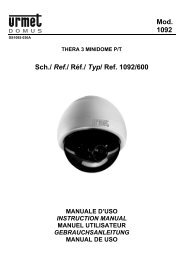
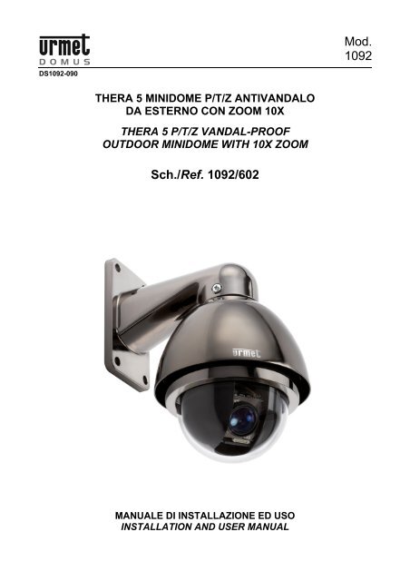
<strong>Mod</strong>.<strong>1092</strong>DS<strong>1092</strong>-090THERA 5 MINIDOME P/T/Z ANTIVANDALODA ESTERNO CON ZOOM 10XTHERA 5 P/T/Z VANDAL-PROOFOUTDOOR MINIDOME WITH 10X ZOOM<strong>Sch</strong>./<strong>Ref</strong>. <strong>1092</strong>/<strong>602</strong>MANUALE DI INSTALLAZIONE ED USOINSTALLATION AND USER MANUAL
ITALIANOINDICE1 Informazioni generali ............................................................................................................................. 31.1 Descrizione del prodotto......................................................................................................... 31.2 Apertura della confezione....................................................................................................... 31.2.1 Contenuto della confezione................................................................................................................... 31.3 Organizzazione del documento.............................................................................................. 32 Importanti norme di sicurezza .............................................................................................................. 43 Procedure di installazione..................................................................................................................... 63.1 Configurazione di un sistema minimale per l’uso di THERA 5............................................... 63.2 Tipologie di installazione ........................................................................................................ 63.2.1 Installazione a parete. ........................................................................................................................... 73.2.2 Requisiti dei cavi per il collegamento .................................................................................................. 133.2.3 Dimensioni dei cavi d’alimentazione.................................................................................................... 134 <strong>Mod</strong>alità di funzionamento .................................................................................................................. 144.1 Funzionamento all’accensione ............................................................................................. 144.2 <strong>Mod</strong>alità di utilizzo tramite tastiera di comando ................................................................... 144.2.14.2.2Sintassi dei comandi eseguibili da tastiera sch.<strong>1092</strong>/620 ................................................................... 15Tipi di comandi eseguibili da tastiera................................................................................................... 154.3 Selezione della dome ........................................................................................................... 164.4 Operazioni di manovra della dome....................................................................................... 164.4.1 Funzioni di brandeggio orizzontale (pan) e verticale (tilt) .................................................................... 164.4.2 Funzioni di modifica ingrandimento (zoom)......................................................................................... 174.4.3 Funzioni di modifica fuoco (focus) ....................................................................................................... 174.4.4 Funzioni di modifica apertura otturatore (iris) ...................................................................................... 174.4.5 Impostazione e richiamo di posizioni preimpostate (preset)................................................................ 184.5 Impostazione delle modalità di funzionamento tramite menu .............................................. 184.5.1 Menu relativo alle informazioni sul prodotto ........................................................................................ 194.5.2 Menu relativo alle visualizzazioni ........................................................................................................ 194.5.3 Impostazioni da menu relative alle programmazioni principali (Control Options) ................................ 204.5.4 Impostazioni da menu relative alle programmazioni principali (Diagnostic Options) ........................... 214.5.5 Impostazioni da menu relative alle programmazioni secondarie (Camera options)............................. 214.5.6 Descrizione del sistema dei menu....................................................................................................... 214.5.7 Descrizione delle voci di menu ............................................................................................................ 224.5.7.1 Cam title – assegnazione di un nome alla dome .......................................................................................... 224.5.7.2 White bal – bilanciamento del bianco ........................................................................................................... 224.5.7.3 Backlight – BLC – compensazione controluce.............................................................................................. 244.5.7.4 Focus– impostazioni dello zoom................................................................................................................... 244.5.7.5 Exposure– esposizione................................................................................................................................. 264.5.7.6 Special– regolazioni speciali......................................................................................................................... 284.5.8 Impostazioni da menu relative alle programmazioni (function programming)...................................... 304.5.8.1 Preset - memorizzazione della posizione e dello zoom della dome ............................................................. 314.5.8.2 Program vectorscan – definizione percorso costituito da preset, pattern e vectorscan................................ 314.5.8.3 Pattern – definizione percorso programmabile ............................................................................................. 334.5.8.4 Sector setup – definizione settori.................................................................................................................. 344.5.8.5 Masking zone- zona di mascheramento ....................................................................................................... 364.5.8.6 Motion – azionamenti automatici................................................................................................................... 364.5.8.7 Alarm in programming – azioni collegate agli allarmi.................................................................................... 394.6 Impostazioni hardware (dip-switch)...................................................................................... 414.6.1 Impostazione della dome..................................................................................................................... 414.6.2 Impostazione dell’indirizzo................................................................................................................... 414.6.3 Impostazioni di baud rate .................................................................................................................... 434.6.4 Impostazioni di protocollo di comunicazione ....................................................................................... 435 Comandi speciali.................................................................................................................................. 446 Caratteristiche tecniche....................................................................................................................... 45DS<strong>1092</strong>-090 2
1 INFORMAZIONI GENERALICaro cliente,La ringraziamo dell’acquisto di questo prodotto.Il presente documento descrive come installare ed utilizzare il modello di minidome THERA 5 URMETDomus S.p.A. <strong>Sch</strong>.<strong>1092</strong>/<strong>602</strong>.Prima di usare l’apparecchiatura, leggere il presente manuale che ne descrive l’uso corretto e sicuro.Conservare questo manuale con attenzione ed in un luogo facilmente reperibile per poterlo consultareprontamente quando necessario.1.1 DESCRIZIONE DEL PRODOTTOLa minidome <strong>Sch</strong>.<strong>1092</strong>/<strong>602</strong> offre elevate prestazioni in termini di qualità video e di manovrabilità, con lapossibilità di riprendere immagini a colori ad alta qualità durante il giorno ed in bianco e nero durante lanotte.Le minidome va abbinata a una tastiera di controllo, es.<strong>Sch</strong>.<strong>1092</strong>/620, <strong>Sch</strong>.<strong>1092</strong>/690 o <strong>Sch</strong>.<strong>1092</strong>/691 o<strong>Sch</strong>.<strong>1092</strong>/692, e tramite questa consente il controllo di brandeggio orizzontale e verticale (pan e tilt) e diingrandimento (zoom) a velocità variabile, per la sorveglianza di aree remote in sistemi TVCC professionali.1.2 APERTURA DELLA CONFEZIONEVerificare che l’imballo ed il contenuto non presentino danni visibili. Se alcune parti non sono presenti orisultano danneggiate, contattare immediatamente il rivenditore. In questi casi non tentare di utilizzare ildispositivo. Se il prodotto dovesse essere rimandato al fornitore, assicurarsi di spedirlo con il suo imballooriginale.1.2.1 CONTENUTO DELLA CONFEZIONE‣N°1 modulo camera.‣N°1 staffa da parete.‣N°1 guarnizione in gomma per staffa da parete.‣N°1 confezione contenente n°1 cacciavite, n°3 viti con guarnizione per fissaggio minidome, n°1guarnizione circolare per staffa da parete, n°1 anello di raccordo metallico.‣N°1 alimentatore dedicato.‣N°1 cavo di collegamento.‣Manuale istruzioni.NOTA BENELa composizione degli accessori a corredo può essere variata senza alcun preavviso.1.3 ORGANIZZAZIONE DEL DOCUMENTOQuesto documento è composto delle seguenti parti fondamentali.‣Una serie di avvertenze ed importanti norme di sicurezza‣Le procedure per l’installazione della minidome, degli accessori utili al loro funzionamento e lenorme per collegare il tutto in un unico sistema video integrato.‣Le modalità di funzionamento in abbinamento ad una tastiera e la gestione avanzate delle opzioni.‣Specifiche tecniche riassuntive.Ognuno dei capitoli che seguono approfondisce uno di questi argomenti.DS<strong>1092</strong>-090 3
2 IMPORTANTI NORME DI SICUREZZASono qui riportate importanti norme da seguirsi scrupolosamente per operare la telecamere <strong>Sch</strong>.<strong>1092</strong>/<strong>602</strong> erelativi accessori in condizioni di completa sicurezza.Nel seguito con il termine “sistema video” si intende una minidome <strong>Sch</strong>.<strong>1092</strong>/<strong>602</strong> comprendente tutto quantopossa servire per renderla operativa (ad esempio, alimentazione, cavi, supporti, tastiera di controllo, od altroancora).Leggere le istruzioniPrima di procedere alla messa in funzione del sistema video, leggere con attenzione tutte le norme disicurezza e le istruzioni operative.Conservare le istruzioniConservare le norme di sicurezza e le istruzioni d'uso per future evenienze.Rispettare le avvertenzePrestare attenzione a tutte le avvertenze riportate sulla minidome ed all'interno del manuale di installazioneed uso.Seguire le istruzioniAttenersi esclusivamente alle istruzioni riportate nel manuale di installazione ed uso.PuliziaScollegare tutte le parti elettriche dalla rete di alimentazione elettrica prima di pulirle.AttacchiNon utilizzare attacchi diversi da quelli raccomandati dal manuale di installazione ed uso in quanto questopotrebbe comportare dei rischi per il prodotto.AccessoriNon posizionare la minidome su carrelli instabili, treppiedi, staffe o tavoli. La minidome potrebbe cadere,ferendo gravemente adulti o bambini e danneggiando seriamente il prodotto stesso. Per l’installazione dellaminidome e la messa in opera del sistema video attenersi alle istruzioni del manuale di installazione ed usoe utilizzare solo gli accessori raccomandati e forniti come accessori alla minidome.AerazioneNon posizionare mai la minidome vicino o sopra radiatori o fonti di calore. Installare la minidome all'interno dizone parzialmente chiuse (quali nicchie, librerie, scaffali) a condizione che sia garantita un'opportunaaerazione e previo rispetto delle istruzioni riportate nel libretto di installazione ed uso.Alimentazione elettricaPrevedere un interruttore per le operazioni di manutenzione della minidome.Collegare la minidome esclusivamente al tipo di alimentazione elettrica indicata sulla targhetta. In caso didubbio relativamente al tipo di alimentazione, consultare il proprio rivenditore.Protezione dei cavi di alimentazioneEffettuare la posa dei cavi di alimentazione in modo che non possano essere calpestati o schiacciati daoggetti posti su di essi, prestando particolare attenzione ai cavi in corrispondenza di spine, viti e all'uscita dalprodotto.FulminiAl fine di proteggere la minidome durante i temporali o quando viene lasciata incustodita e non in uso perlunghi periodi, scollegare l'alimentazione e il cablaggio. Questo impedirà il danneggiamento del sistemavideo in caso di caduta di fulmine e sovraccarico della linea elettrica.SovraccarichiNon sovraccaricare l'alimentazione elettrica e le prolunghe poiché ciò comporta rischio di incendio e discosse elettriche.Infiltrazioni di liquidi e oggettiNon inserire oggetti di alcun tipo attraverso le aperture della minidome in quanto potrebbero toccare punti adalta tensione con il rischio che si generi un incendio o una scossa elettrica. Non versare liquidi di alcun tiposul dispositivo.DS<strong>1092</strong>-090 4
3 PROCEDURE DI INSTALLAZIONEQuesta sezione fornisce istruzioni dettagliate per l’installazione delle minidome THERA 5 Urmet Domus. Leistruzioni presuppongono da parte dell’installatore una buona conoscenza delle tecniche di installazione el’adozione di metodi d’installazione sicuri.3.1 CONFIGURAZIONE DI UN SISTEMA MINIMALE PER L’USO DI THERA 5La minidome THERA 5 contiene un ricevitore incorporato che decodifica i comandi provenienti dalla tastieradi comando <strong>Sch</strong>.<strong>1092</strong>/620 (fare riferimento al capitolo 4.2); Il funzionamento richiede quindi almeno unatastiera di comando. Questa, oltre alla configurazione dei parametri di funzionamento, gestisce lefunzionalità di brandeggio sull'asse orizzontale (360° continui) e sull'asse verticale (180°), di zoommotorizzato, di richiamo e programmazione delle sequenze predefinite di THERA 5.3.2 TIPOLOGIE DI INSTALLAZIONEL'installazione di THERA 5 si articola in due possibili soluzioni.‣a parete tramite staffa standard.‣a parete tramite Kit con staffa e power box di collegamento IP66 <strong>Sch</strong>. <strong>1092</strong>/628Nota BeneIndipendentemente dal tipo di installazione si consiglia di:‣prevedere un interruttore per le operazioni di manutenzione della minidome.‣assicurarsi che ai capi delle linee RS - 485 siano inserite le adeguate resistenze di terminazione(120 Ω ¼ W) non fornite a corredo.DS<strong>1092</strong>-090 6
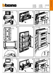
3.2.1 INSTALLAZIONE A PARETE.Prima d’iniziare l’installazione, assicurarsi che tutte le unità da collegare non siano alimentate.Posizionare sulla staffa da parete l’anello di tenuta in gomma (oring), a corredo, nella apposita sede.Inserire il cavo di collegamento della dome, in dotazione, all’interno della staffa fino a farlo fuoriusciredalla parte opposta.Posizionare l’anello di raccordo, in dotazione, nella sede superiore della dome avendo cura di allineare itre fori presenti sulla dome ai tre fori presenti sull’anello aiutandosi con i riferimenti presenti su entrambele parti.Collegare la morsettiera del cavo alla morsettiera della dome come indicato in figura.DS<strong>1092</strong>-090 7
Bloccare la staffa alla dome utilizzando le viti con la rondella in gomma, a testa bombata a corredoavvitandole saldamente nei fori presenti ai lati della staffa.Posizionare la dome nel punto prescelto della parete avendo cura di far passare il cavo attraversol’asola situata nella staffa o praticare un ulteriore foro sulla parete in corrispondenza del cavo in uscitadalla staffa di diametro sufficiente al passaggio del cavo intestato).Fissarla saldamente alla parete utilizzando i 4 fori situati nella base della staffa mediante 4 viti M6 nonfornite in dotazione. Qui di seguito si riportano per comodità gli interassi di foratura in mm.7050120100N°4 fori 8DS<strong>1092</strong>-090 8
INSTALLAZIONE A PARETE CON POWER BOX SCH.<strong>1092</strong>/628 (Non a corredo)Prima d’iniziare l’installazione, assicurarsi che tutte le unità da collegare non siano alimentate.Eseguire i fori sulla superficie di appoggio prevista e fissare il Power Box utilizzando i 4 fori presenti alleestremità del dispositivo.Con un cacciavite e croce svitare le viti 4 presenti sul frontale del Power Box per poterlo aprire edeseguire i collegamenti di seguito descritti.SVITARE PER APRIRESVITARE PER APRIREUna volta aperto il Power Box eseguire i collegamenti relativi alla linea RS485 inserendo attraverso ilforo più grande presente sul lato inferiore corredato di pressa cavo, un cavo a due conduttori dellalunghezza e sezione adeguati allo scopo (vedi Requisiti per i cavi di collegamento) da collegarsi aimorsetti AA (+) e BB (-) presenti sulla scheda.Eseguire il collegamento del cavo tipo RG relativo al segnale video inserendo il cavo di lunghezza etipologia adeguata allo scopo (vedi Requisiti per i cavi di collegamento) nel foro più grande corredato dipressa cavo presente sul lato inferiore del Power Box (lo stesso usato per la linea RS485) e collegarlo alconnettore BNC presente nel cavo in dotazione al Box.DS<strong>1092</strong>-090 9
Eseguire il collegamento dell’alimentazione a 230 Vca inserendo il cavo di sezione e lunghezzaadeguata allo scopo (vedi Requisiti per i cavi di collegamento) nel foro più piccolo corredato di pressacavo presente nel lato inferiore del Box e collegandolo ai morsetti presenti sulla scheda dopo averrimosso il coperchio di protezione.Riposizionare il coperchio di protezione.Richiudere il Power Box nel modo inverso alla sua apertura.Inserire il cavo di collegamento della dome, in dotazione, all’interno della staffa fino a farlo fuoriusciredalla parte opposta.Bloccare la staffa al Power Box per mezzo delle 4 viti come indicato in figura.Posizionare sulla staffa da parete l’anello di tenuta in gomma (oring), a corredo, nella apposita sede.ANELLO DI TENUTA INGOMMA (ORING)CAVO DICOLLEGAMENTOVITI DI BLOCCOVITI DI BLOCCODS<strong>1092</strong>-090 10
Posizionare l’anello di raccordo, in dotazione, nella sede superiore della dome avendo cura di allineare idue fori presenti sulla dome ai due fori presenti sull’anello aiutandosi con i riferimenti presenti suentrambe le parti.Collegare la morsettiera del cavo alla morsettiera della dome come indicato in figura.Bloccare la staffa alla dome utilizzando le tre viti con la rondella in gomma, a testa bombata a corredoavvitandole saldamente nei fori presenti ai lati della staffa.UTILIZZARE LE VITI IN DOTAZIONEPER BLOCCARE LA MINIDOMEALLA STAFFADS<strong>1092</strong>-090 11
COLLEGAMENTICollegare il cavo in dotazione alla dome per mezzo delle morsettiere.Collegare la seconda estremità del cavo al dispositivo video per mezzo del connettore BNC maschio.Collegare i due fili della RS485 per mezzo di morsettiera o eseguendo una saldatura alla borchia dellatastiera (<strong>Sch</strong>.<strong>1092</strong>/620) rispettando le polarità : ARANCIO + (positivo) - GIALLO – (negativo).Collegare i due fili di alimentazione per mezzo di morsettiera o eseguendo una saldatura ai due filidell’alimentatore fornito in dotazione (non è necessario rispettare le polarità).Se la dome è l’ultimo dispositivo della linea RS485 (vedi COLLEGAMENTO LOGICO DELLA LINEARS485),collegare una resistenza da 120 Ohm ¼ w non in dotazione , sulla linea RS485.Effettuare i collegamenti come indicato nel “DETTAGLIO DEI COLLEGAMENTI”Collegare l’alimentatore alla presa di rete.CONFIGURAZIONECavo di collegamentoAlimentatoreDomeCOAXSE IL DISPOSITIVO E’L’ULTIMO DELLALINEAINSERIRE LA RESISTENZA DA 120 OHM¼ WRS485CONFIGURAZIONE LOGICA DELLA LINEA RS485.Inserire resistenzaNota BeneFigura 1: CONFIGURAZIONE MINIMANel caso di collegamento di più Dome, si consiglia la configurazione a cascata, con collegamenti di tipo“entra-esci” su ciascun dispositivo. In ogni caso, la somma delle lunghezze delle singole tratte della lineaRS485 non deve mai superare 1200m.Si ricorda di inserire sempre la resistenza di terminazione sull’ultima Dome della linea.DS<strong>1092</strong>-090 12
3.2.2 REQUISITI DEI CAVI PER IL COLLEGAMENTOSono richiesti tre tipi di cavo:1. Il cavo video, che trasporta il segnale video composito standard alla postazione di osservazione remota.Normalmente si utilizza un cavo coassiale da 75 Ohm.2. Il cavo di alimentazione per la minidome THERA 5 (alimentatore da 24Vca). Per determinare ledimensioni del cavo, vedere la sezione “Dimensioni dei cavi d’alimentazione” di questo manuale.3. Il cavo di comando RS485, che distribuisce i comandi dalla tastiera a THERA 5. È necessario un cavotwistato a due conduttori, non schermato. Si consiglia un cavo di diametro 0,64 mm (22AWG).3.2.3 DIMENSIONI DEI CAVI D’ALIMENTAZIONEÈ importante determinare la dimensione corretta del cavo che trasporta i 24V di alimentazione di THERA 5 .Se il cavo è troppo piccolo sull’apparecchiatura, la caduta di tensione da esso determinata può causare unfunzionamento improprio. La seguente formula determina la tensione fornita a THERA 5 al variare delledimensioni del cavo.dove:VD VTPD RW DV 500TWV D = Tensione su THERA 5.V T = Tensione del trasformatore.P D = Assorbimento di THERA 5 in Watt.R W = Resistenza del cavo in Ohm per metro (vedere tabella sottostante).D W = Lunghezza del cavo (in metri) tra THERA 5 e l’alimentatoreDiametro del filo (mm)Resistenza (Ohm/m)2,60 3,35/10002,05 5,32/10001,63 8,46/10001,29 13,42/10001,02 21,36/10000,81 34,12/10000,64 54,14/1000Diametro del filo e valori di resistenzaLa tabella sottostante fornisce le lunghezze consigliate per il cavo di una THERA 5Diametro del filo (mm)Lunghezza massima dei caviper versione da esterno (m)2,60 2002,05 1251,63 801,29 501,02 300,81 200,64 10Lunghezza massima dei cavi di alimentazioneDS<strong>1092</strong>-090 13
4 MODALITÀ DI FUNZIONAMENTO4.1 FUNZIONAMENTO ALL’ACCENSIONEAlla prima accensione, la dome utilizza le impostazioni di default di fabbrica. Le impostazioni, se variate,vengono memorizzate in maniera permanente e sono disponibili anche alle successive accensioni delladome. Da notare che in qualsiasi momento si possono riportare le impostazioni al loro valore di default difabbrica agendo sulla voce di menu opportuna.In fase di accensione la dome si comporta nel seguente modo.1. La dome effettua una fase di calibrazione visualizzando nel menù OSD (On Screen Display) unmessaggio riportante le seguenti informazioni: protocollo usato, parametri di comunicazione,indirizzo della dome e versione softwareControllare che i dati siano quelli richiesti per il funzionamento.In caso contrario, fare riferimento alla sezione di questo documento che illustra come impostarecorrettamente la dome (cap. 4.7).PTOL: PELCO-DCOMM: 9600ADDR: 01SW version X.XXNota BenePrendere nota della versione SW in caso di richiesta di assistenza tecnica2. Al termine della fase di calibrazione, la dome si pone in fase di attesa comportandosi secondoquanto impostato nel menu di impostazione delle modalità di funzionamento alla voce POWER UPACTION dal menu . La dome mantiene tale comportamentofino a che non si manda un qualunque comando da tastiera. Il comportamento della dome in questafase può essere ad esempio il posizionamento in un punto fisso oppure l’esecuzione di unascansione nel campo di visibilità.Per maggiori dettagli si rimanda alla descrizione particolareggiata della voce di menu POWER UPACTION.4.2 <strong>Mod</strong>alità di utilizzo tramite tastiera di comandoDopo la fase di calibrazione la dome è pronta ad accettare comandi inviati da tastiera di comando.E’possibile utilizzare qualsiasi tastiera con caratteristiche di protocollo di comunicazione, baud rate ecomandi compatibili con la dome. Di seguito viene descritto l’uso della tastiera <strong>Sch</strong>.<strong>1092</strong>/620 (vedi figurasuccessiva).Tastiera di controllo <strong>Sch</strong>.<strong>1092</strong>/620DS<strong>1092</strong>-090 14
4.2.1 SINTASSI DEI COMANDI ESEGUIBILI DA TASTIERA SCH.<strong>1092</strong>/620È possibile dare comandi da tastiera usando tasti singoli, oppure una combinazione di tasti.La sintassi di descrizione del comando formato da tasti è la seguente.Sintassi di comandi formati da tastiLa sintassi usata in questo manuale per i comandi formati da tasti consiste in una serie di elementi chepossono essere parole oppure numeri a tre cifre decimali. Ogni comando è sempre delimitato da parentesied ogni elemento è separato da virgole. Ogni parola o cifra decimale usata nella sintassi è l’identificativo diun corrispondente tasto nella tastiera <strong>Sch</strong>.<strong>1092</strong>/620. Le parole possono essere racchiuse da parentesitonde, da parentesi quadre o da nessuna parentesi. I numeri a tre cifre decimali non sono mai racchiusi fraparentesi.In seguito viene mostrato in dettaglio come usare i comandi con alcuni esempi applicativi.Uso di un tasto singoloLa pressione di un singolo tasto può provocare un’azione sulla dome. Ad esempio, il comando seguenteprovoca un ingrandimento dell’inquadratura. La sottolineatura del testo in stampatello indica l’uso del tasto.TELEUso combinato di tastiLa pressione combinata in rapida successione di una serie di tasti permette di estendere l’insieme deicomandi. Ad esempio, il comando seguente, che seleziona la dome all’indirizzo 1, si esegue premendo consingola pressione i tasti:CAM + 1 + ENTER4.2.2 TIPI DI COMANDI ESEGUIBILI DA TASTIERAI comandi possono essere dei seguenti quattro tipi.1. Selezione della dome.2. Operazioni di manovra della dome (brandeggio, zoom, impostazioni fuoco ed iris, posizioni preimpostate).3. Impostazioni delle modalità di funzionamento della dome tramite menu.4. Comandi vari richiamabili in maniera veloce da tastiera.Nei paragrafi seguenti verranno illustrati in maggior dettagli le modalità di esecuzione di questi comandi.DS<strong>1092</strong>-090 15
4.3 SELEZIONE DELLA DOMEPrima di poter eseguire qualunque comando, si rende necessario selezionare la dome su cui si vuole agire.Ad esempio, per selezionare la dome numero 1 si usa il seguente comando:CAM + 1 + ENTERA completamento dell’operazione il display della tastiera indica : A001.4.4 OPERAZIONI DI MANOVRA DELLA DOMEUna volta selezionata, la dome può essere manovrata direttamente da tastiera per quanto riguarda leseguenti operazioni che saranno descritte di seguito.Funzioni di brandeggio orizzontale (pan) e verticale (tilt).Funzioni di modifica ingrandimento (zoom), fuoco (focus) ed apertura otturatore (iris).Impostazione e richiamo di posizioni preimpostate (Preset).Queste funzioni sono direttamente accessibili utilizzando un singolo tasto, od ancora una semplicecombinazione di tasti.4.4.1 FUNZIONI DI BRANDEGGIO ORIZZONTALE (PAN) E VERTICALE (TILT)La posizione di puntamento della dome può essere impostata agendo sui tasti indicati con il simbolo dellafreccia della tastiera <strong>Sch</strong>.<strong>1092</strong>/620. L’orientamento verticale delle frecce genera un brandeggio verticale(tilt), mentre l’orientamento orizzontale genera un brandeggio orizzontale (pan).L’escursione massima del pan è compresa fra 0 e 360 gradi a rotazione continua mentre quella del tilt ècompresa fra –2° e 90°gradi (dome in posizione verticale).Si può modulare la velocità di rotazione sia del pan che del tilt utilizzando i tasti numerici da 1 a 9 prima diagire sui tasti freccia in modo da ottenere velocità di rotazione della dome che sono crescenti al crescere delnumero selezionato.Si rammenta tuttavia che il valore di massima velocità di rotazione ottenibile agendo sui tasti numerici non èsempre uguale a quello impostato nelle opzioni di funzionamento. Esso infatti dipende dal valoredell’opzione PROPORTIONAL SPEED, nel menu CONTROL OPTIONS. Se il valore di questa opzione è ON,la massima velocità di rotazione ottenibile premendo il tasto numerico "9” viene ridotta in manieraproporzionale all’ingrandimento usato, in modo da ottenere un migliore inquadratura.Uso del brandeggio orizzontale (pan)Premendo il tasto freccia RIGHT si fa ruotare la dome orizzontalmente in senso orario , premendo il tastofreccia LEFT si fa ruotare la dome orizzontalmente in senso antiorario.Se non sono impostate opzioni avanzate (ad esempio, limiti di fine corsa impostati ed abilitati) la rotazionedella dome può essere continua senza interruzioni.Nel menu SETTING1 • MOTION • MANUAL LIMIT è possibile limitare la corsa del pan tra 2 angoli.Uso del brandeggio verticale (tilt)Premendo il tasto freccia UP si fa ruotare la dome verticalmente verso l’alto ,premendo il tasto frecciaDOWN la dome ruota verso il basso. La rotazione della dome è limitata verso l’alto dal piano orizzontale everso il basso dall’asse verticale.Tuttavia, il comportamento in prossimità all’asse verticale cambia considerevolmente a seconda che lafunzione AUTO FLIP è attivata oppure no (è attivata di default di fabbrica).Con AUTO FLIP disattivato, se si mantiene premuto il tasto DOWN, la dome si ferma in posizioneperfettamente verticale e non ruota oltre.Con AUTO FLIP attivato, se si mantiene premuto il tasto DOWN, la ripresa della dome prosegue oltrel’asse verticale. Questo perché una volta raggiunto l’asse verticale la dome compie automaticamente unarotazione orizzontale di 180 gradi e prosegue la traiettoria iniziale.DS<strong>1092</strong>-090 16
La funzione di AUTO FLIP consente di seguire un soggetto che arrivando da una direzione passa sotto ladome e prosegue in linea retta. Per fare questo, basta mantenere premuto il tasto DOWN seguendo ilmovimento dell’oggetto.4.4.2 FUNZIONI DI MODIFICA INGRANDIMENTO (ZOOM)L’ingrandimento della dome può essere variato agendo con i comandi TELE e WIDE. Agendo con il comandoTELE si ingrandisce il particolare, mentre agendo con WIDE si allarga l’inquadratura.L’ingrandimento può essere impostato fra i valori di X10 (ottico) o X10 (digitale), combinati fra zoom otticoe zoom digitale. Per maggiori dettagli si rimanda alla sezione opportuna delle impostazioni delle modalità difunzionamento.4.4.3 FUNZIONI DI MODIFICA FUOCO (FOCUS)La modifica del fuoco della dome può essere effettuata in maniera manuale agendo con i comandi NEAR eFAR.Siccome la messa a fuoco automatica (funzione autofocus) è sempre abilitata ed attiva ne consegue che laregolazione manuale, impostata con i comandi NEAR e FAR, si manterrà solo fino a quando non si agirà suun comando di pan, tilt o zoom. In questo caso, l’autofocus interverrà nuovamente a regolare il fuoco inmaniera automatica.Per ulteriori dettagli sulla regolazione della messa a fuoco e sulle varie opzioni si rimanda alla sezioneopportuna delle impostazioni delle modalità di funzionamento.NOTA BENELa funzione autofocus può non funzionare correttamente nei seguenti casi:‣L’oggetto da mettere a fuoco non è al centro dell’immagine‣Ci sono oggetti sia vicini che lontani‣L’oggetto e soggetto a forte illuminazione‣L’oggetto è dietro un vetro coperto di gocce o polvere‣L’oggetto si muove molto velocemente‣L’oggetto è poco illuminato‣L’oggetto è troppo grande nell’immagine4.4.4 FUNZIONI DI MODIFICA APERTURA OTTURATORE (IRIS)L’apertura dell’iris può essere effettuata in maniera manuale agendo sui comandi OPEN e CLOSE.Tuttavia, se è abilitata (vedi menù EXPOSURE-ESPOSIZIONE) l’opzione di apertura dell’iris regolata inmaniera automatica (come per default di fabbrica) la regolazione manuale impostata con i comandi OPEN eCLOSE si manterrà solo fino a quando non si agirà su un comando di pan, tilt o zoom. In questo casol’apertura sarà nuovamente regolata in maniera automatica.Per ulteriori dettagli sulla regolazione dell’apertura dell’iris si rimanda alla sezione opportuna delleimpostazioni delle modalità di funzionamento.DS<strong>1092</strong>-090 17
4.4.5 IMPOSTAZIONE E RICHIAMO DI POSIZIONI PREIMPOSTATE (PRESET)La minidome THERA 5 memorizza fino a 128 configurazioni di pan, tilt e zoom (dette posizioni preimpostateoppure preset) in modo tale da permettere il richiamo di una di queste posizioni in un qualsiasi momento.Nota BeneNella memorizzazione dei preset occorre tenere in considerazione che alcuni sono riservati e che nonpossono essere ne memorizzati ne utilizzati per posizionare la dome.‣Dal n°51 al 63 e dal 78 al101 sono riservati ai comandi di gestioneLa modalità per impostare i preset liberi e richiamarli è illustrato dai seguenti esempi.Esempio di impostazione di preset numero 321. Si posiziona la dome su una determinata configurazione di pan, tilt e zoom.2. Si digita il comando PRESET + 32 + ENTERDa questo momento in poi, per posizionare la dome in corrispondenza della posizione (preset) preimpostatasarà sufficiente digitare il comando CALL + 32 + ENTERNota BeneUna successiva operazione di impostazione cancella inevitabilmente il valore memorizzato.I valori di Preset vengono salvati in un’area di memoria permanente della dome dove sono mantenuti anchese si scollega l’alimentazione. Tuttavia, il ripristino delle condizioni di default di fabbrica cancella tutti i valoridi Preset impostati.Avvertenza: valori di Preset memorizzano le coordinate di un sistema di riferimento angolare per cui èpossibile che dopo un prolungato uso di comandi di brandeggio l’origine del sistema di riferimento possaperdere l’allineamento con la parte di controllo meccanica della dome. Questo si manifesta con piccoleimprecisioni nel posizionamento dei preset. In tal caso si raccomanda di eseguire una calibrazione delsistema di coordinate angolari utilizzando il comando {DOME RESET}. Tale calibrazione è la stessa cheviene eseguita all’accensione della dome.4.5 IMPOSTAZIONE DELLE MODALITÀ DI FUNZIONAMENTO TRAMITE MENUSi può accedere al menu di impostazione delle modalità di funzionamento utilizzando il seguente comandodalla tastiera <strong>Sch</strong>. <strong>1092</strong>/620.CALL + 90 + ONA questo punto, appare la seguente schermata di primo livello del menu.THERA 5> 1 Language English2 Dome Information3 Display Options4 Control Options5 Diagnostic Options6 Camera Options7 Function ProgrammingIRIS CLOSE to ExitPer scorrere le voci del menu basta agire sui tasti freccia posizionandosi in corrispondenza della voce dimenu da selezionare: a questo punto, usare il comando OPEN per entrare nel menu di secondo livelloselezionato.Una volta entrati in un menu, per tornare indietro al menu di livello precedente sarà sufficiente selezionare ilcomando CLOSEPer uscire completamente dai menu di qualunque livello è sufficiente selezionare il comando CLOSE.DS<strong>1092</strong>-090 18
Opzione Valore SpiegazioneLanguage ENGLISH I menu sono solo in lingua inglese.Dome Information Menu relativo alle informazioni sul prodotto (vedi par. 4.5.1).Display Informations Menu relativo alle visualizzazioni (vedi par. 4.5.2).Control Options Menu relativo alle programmazioni principali (vedi par. 4.5.3).Diagnostic Options Menu relativo alle programmazioni secondarie (vedi par. 4.5.4).Camera OptionsFunction ProgrammingMenu relativo alla impostazione del testo da associare alla dome(vedi par. 4.5.5).Menu relativo alla programmazione e memorizzazione dei Preset,Vector Scan , Pattern , Motion e Allarmi.4.5.1 MENU RELATIVO ALLE INFORMAZIONI SUL PRODOTTODal menu di primo livello, scegliendo si ottengono le informazioni relative al modulo,protocollo, baudrate,all’indirizzo della dome, alla versione.Dome InformationCameraSAMSUNGProtocolPelco DBaudrate 9600Dome NO 3Version X.XXIRIS CLOSE to ExitQueste informazioni non possono essere variate in questo menu.4.5.2 Menu relativo alle visualizzazioniIl menu permette di abilitare/disabilitare i testi che devono comparire incorrispondenza delle varie funzioni di THERA 5.Display OptionsCoordinates ONStart-Up Scr Msg ONIRIS CLOSE To ExitOpzione Valore SpiegazioneCOORDINATESSTART-UP SCR MSGON/OFFON/OFFAbilitazione/disabilitazione della visualizzazione delle coordinatedi pan e tilt corrispondenti alle immagini visualizzate.Abilitazione/disabilitazione della visualizzazione delle informazionisul prodotto al momento della accensione della Dome (vedi par.4.5.1).DS<strong>1092</strong>-090 19
4.5.3 Impostazioni da menu relative alle programmazioni principali (Control Options)Dal menu di primo livello, scegliendo e relativi sotto menu si ottiene l’accesso aiprincipali menu per la programmazione di THERA 5CONTROL OPTIONS>1 Auto Flip ON2 Proportional Speed ON3 Pan Reverse OFF4 Tilt Reverse OFF5 Vector Scan Still OFF6 Auto Focus PTZ7 Auto AE PTZ8 VectorScan AF ON9 +2 Tilt Limit OFF10 Speed limit OFFIRIS CLOSE to ExitOpzione Valore SpiegazioneAuto FlipProportional SpeedOn/offON/OFFSe questa modalità è attivata (ON), è possibile seguire latraiettoria di un soggetto che si muove e passa sotto la domeagendo solo con lo spostamento verticale del joystick. Questoperché una volta raggiunta la posizione verticale, la dome compieun movimento automatico di pan di 180 gradi per riposizionarsi epoter riprendere la corsa del tilt.Se questa modalità è attivata (ON), la velocità di pan e tiltapplicata da tastiera è proporzionale allo zoom impostato, in modoche la velocità di movimento diminuisca all’aumentare dello zoom.Pan RiverseTilt RiverseON/OFFON/OFFVectorScan Still ON/OFF FUNZIONE NON ABILITATASe questa modalità è attivata (ON), i comandi del joistick relativialla funzione di pan risultano invertiti.Se questa modalità è attivata (ON), i comandi del joistick relativialla funzione di tilt risultano invertiti.Auto FocusAuto AEON/OFF/PTZ/ZON/OFF/PTZ/ZSe attivato con ON la Dome eseguirà in automatico il controllodella messa a fuoco delle immagini. Se attivato con PTZ la Domeeseguirà la messa a fuoco solo durante l’utilizzo delle funzioniPan, Tilt e Zoom. Se attivato con Z la Dome eseguirà la messa afuoco delle immagini esclusivamente con l’utilizzo della funzionezoom.Se attivato con ON la Dome eseguirà in automatico il controllodella esposizione delle immagini. Se attivato con PTZ la Domeeseguirà il controllo solo durante l’utilizzo delle funzioni Pan, Tilt eZoom. Se attivato con Z la Dome eseguirà il controlloesclusivamente con l’utilizzo della funzione zoom.VectorScan AF ON/OFF FUNZIONE NON ABILITATA+2 Tilt Limit ON/OFFSpeed limitON/OFFSe attivo con ON il limite di tilt della Dome aumenta di 2gradipassando da 0° a -2°.Se attivata con ON, questa funzione riduce della metà la velocitàdi spostamento della dome precedentemente impostata.DS<strong>1092</strong>-090 20
4.5.4 IMPOSTAZIONI DA MENU RELATIVE ALLE PROGRAMMAZIONI PRINCIPALI (DIAGNOSTICOPTIONS)Dal menu di primo livello, scegliendo e relativi sotto menu si ottiene l’accesso aiprincipali menu per la gestione e la diagnostica di THERA 5Diagnostic Options>1 Clear Memory2 Restore Def Setting3 Color System PAL4 Dome ResetIRIS CLOSE to ExitOpzione Valore SpiegazioneSe attivata la funzione per mezzo del tasto OPEN e premendonuovamente il tasto OPEN per conferma, vengono cancellate tutteClear Memoryle memorizzazioni eseguite dell’utente relative ai Preset eVectorScan Still. (Sono escluse dalla cancellazione tutte lepersonalizzazioni impostate dall’utente relative alle impostazioni diutilizzo della Dome).Se attivato esegue un ripristino di tutti i dati di default presentiRestore Def Settingsulla Dome ad esclusione dei dati memorizzati dall’utente relativiai preset e ai VectorScan Still.Color System PAL/NTSC Utilizzare solo il sistema PAL.Dome ResetEsegue un RIAVVIO del dispositivo senza perdere le impostazionieseguite dall’utente. La dome esegue un riposizionamento.4.5.5 IMPOSTAZIONI DA MENU RELATIVE ALLE PROGRAMMAZIONI SECONDARIE (CAMERAOPTIONS)Dal menu di primo livello, scegliendo e relativi sotto menu si ottiene l’accesso ai menudella telecamera per la programmazione del modulo camera.4.5.6 DESCRIZIONE DEL SISTEMA DEI MENUUna volta impartito il comando di accesso al menu apparirà a monitor la finestra iniziale di accessoal menùOSD del modulo camera.E’ possibile selezionare le voci per mezzo dei tasti “freccia” della tastiera o .Una volta selezionata la voce voluta, è possibile variare il parametro utilizzando il tasto scegliendo fra leopzioni disponibili visualizzabili premendo ripetutamente il tasto .Per confermare le impostazioni volute selezionare END e premere Il tasto CLOSE.Il simbolo indica che selezionando la voce ad esso abbinato si accederà ad un successivo sottomenunel quale sarà possibile eseguire ulteriori variazioni.CAM TITLEWHITE BALBACKLIGHTMOTION DETFOCUSEXPOSURESPECIALRESETENDMAIN SETUPONATWLOWONDS<strong>1092</strong>-090 21
CAM TITLEWHITE BALBACKLIGHTOpzione Valore SpiegazioneMOTION DETFOCUS /EXPOSURE /SPECIAL /RESET /END /ON OFFMANUAL AWC-SET ATWLOW MIDDLE HIGH OFFON OFF4.5.7 DESCRIZIONE DELLE VOCI DI MENU4.5.7.1 Cam title – assegnazione di un nome alla domeQuesta opzione permette di nominare la domeutilizzando fino ad un massimo di 20caratteri. (Vedi oltre)Questa opzione consente di selezionare lamodalità di bilanciamento del bianco. (Vedioltre)Questa opzione consente di selezionare illivello di compensazione di controluce.(Vedi oltre)SELEZIONARE SOLO OFF (per configurare lafunzione Motion Detector utilizzare lafunzione presente nel menù principaleFunction Programming)Questa opzione consente di selezionare iparametri relativi al funzionamento zoomdella dome. (Vedi oltre)Questa opzione consente di eseguire leregolazioni relative all’esposizionedell’ottica. (Vedi oltre)Questa opzione consente di attivarefunzioni speciali. (Vedi oltre)Questa funzione consente di ripristinaretutte le variazioni eseguite dall’utenteriportando la dome allo stato iniziale.Questa opzione consente di uscire dal menuprincipale e tornare al menù OSD.Questa funzione consente di “nominare” la dome e di visualizzare il nome a monitor nella posizione preferita.Selezionando questa voce di menu è possibile scegliere fra le opzioni ON e OFF.Selezionando ON e premendo il tasto OPEN si accede al seguente sottomenu nel quale è possibilenominare la dome.ABCDEFGHIJKLMNOPQRSTUVWXYZabcdefghijklmnopqrstuvwxyz0123456789 ()-/#*!?,.CLR POS ENDUtilizzare i tasti “freccia” per spostarsi sopra il carattere voluto.Premere il tasto OPEN per confermarlo.Selezionare CLR per cancellare i caratteri selezionati.Per cancellare solo uno o più caratteri posizionarsi per mezzo dei tasti “freccia” sopra lo “spazio” nellaposizione successiva al numero 9 e precedente al simbolo (e premere OPEN.Selezionando POS e premendo OPEN si accede al seguente sottomenu:CAM TITLE POS SETUPto Locate, then SETUtilizzando I tasti “freccia” è possibile definire la posizione sullo schermo nel quale apparirà il nome delladome.Premere CLOSE per tornare al menu precedente.Selezionare END e premere CLOSE per tornare al menu precedente.4.5.7.2 White bal – bilanciamento del biancoDS<strong>1092</strong>-090 22
Questa funzione consente di selezionare la modalità del bilanciamento del bianco.Selezionando questa voce di menu è possibile scegliere fra le opzioni MANUAL, AWC-SET e ATW.MANUALOpzione Valore SpiegazioneAWC-SET /ATW MODERED ÷ BLUEOUTDOOR INDOORQuesta opzione consente di regolaremanualmente il bilanciamento del bianco.Auto White Balance: regolazione automaticaper interni da utilizzare in ambienti conbassa luce o in caso di presenza di lucifluorescentiAuto Tracking White <strong>Mod</strong>e: regolazioneautomatica basata sulla rilevazionedell’ambiente circostante (esterno ointerno).END / Consente di uscire dal sottomenu.MANUALSelezionando MANUAL e premendo il tasto OPEN si accede al seguente sottomenu:WHITE BAL MANUAL SETUPREDBLUEEND35 ■■■■■■■█■■■55 ■■■■█■■■■■■Questa opzione consente di regolare manualmente il bilanciamento del bianco in condizioni di luce estreme(inquadrature con grandi varietà di colori ma assenza di bianco, in ambienti chiusi con illuminazioneartificiale fluorescente colorata,ecc.);Nota BeneSi consiglia di non usare questa modalità se non strettamente necessario.Utilizzare i tasti “freccia” per spostarsi sopra la voce desiderata e incrementare o decrementare il valoreindicato.Eseguite le regolazioni posizionarsi sopra END e premere CLOSE per tornare al menu precedente.AWC-SETSelezionando AWC-SET e premendo il tasto OPEN si attiva il bilanciamento del tipo Auto White Bilance,tipicamente per interni.Premere CLOSE per tornare al menu precedente.Selezionare END e premere CLOSE per tornare al menu precedente.ATWSelezionando ATW e premendo il tasto OPEN si accede al seguente sottomenu:WHITE BAL MODEATW MODEENDOUTDOORPer mezzo dei tasti “freccia” è possibile variare l’indicazione OUTDOOR (per esterni) in INDOOR (perinterni).Premere CLOSE per tornare al menu precedente.Selezionare END e premere CLOSE per tornare al menu precedente.DS<strong>1092</strong>-090 23
4.5.7.3 Backlight – BLC – compensazione controluceUn oggetto inquadrato con forte luce proveniente da dietro solitamente appare scuro e poco visibile rispettoal resto dell’immagine. La funzione BLC permette di ovviare a questo inconveniente ed ottenere una buonacompensazione.Selezionando questa voce di menu è possibile scegliere fra le opzioni OFF (disattivo), LOW (bassa),MIDDLE (media) e HIGH (alta).4.5.7.4 Focus– impostazioni dello zoomQuesta funzione consente di accedere al sottomenu di impostazioni delle regolazioni della dome.Selezionando questa voce di menu e premendo OPEN si accede al seguente sottomenu:FOCUS SETUPMODEZOOM TRKZOOM SPEEDD-ZOOMDISP ZOOM MAGZOOM POS INITLENS INITENDMANUALONFASTOFFONONOpzione Valore SpiegazioneMODEZOOM TRKZOOM SPEEDMANUAL ÷ AUTO ÷ONE-PUSHON ÷ OFFFAST ÷ SLOWConsente di selezionare il modo di messa afuoco della dome. (Vedi oltre)Se l’opzione selezionata è ON l’otticadella dome eseguirà in continuo la messa afuoco automatica.Consente di selezionare la velocità dimessa a fuoco della dome. La funzione NONè attivabile se l’opzione MODE èselezionata in AUTO e l’opzione ZOOM TRK èselezionata in ON. (Vedi oltre)D-ZOOMDISP ZOOM MAGON ÷ OFFON ÷ OFFZOOM POS INIT ON ÷ OFF FUNZIONE NON ATTIVALENS INITENDConsente di abilitare/disabilitare lo zoomdigitale. In caso di abilitazione èpossibile regolare il valore inpercentuale dello zoom (x2 min. – x10max.). (Vedi oltre)Se l’opzione selezionata è ON vienevisualizzato a monitor l’impostazione dizoom attiva ( x2 min. – x10 max). Con lafunzione D-ZOOM attiva è possibilearrivare a x100 max.La funzione esegue l’inizializzazionedell’ottica della dome. (Vedi oltre)Consente di uscire dal sottomenu.DS<strong>1092</strong>-090 24
MODESelezionando MODE è possibile scegliere fra le opzioni MANUAL (manuale), AUTO (automatica) e ONE-PUSH (una pressione).Selezionando MANUAL e premendo OPEN si accede al seguente sottomenu:ZOOM/FOCUS POS SETUP:TELE:NEAR:WIDE:FARPress SET to ReturnUtilizzando I tasti “FOCUS” e “ZOOM” è possibile eseguire le regolazioni desiderate.TELE (avvicina l’immagine); WIDE (allarga l’immagine); NEAR (vicino); FAR (lontano).Premere CLOSE per tornare al menu precedente.Selezionare END e premere CLOSE per tornare al menu precedente.Selezionando AUTO e premendo OPEN si accede al seguente sottomenu:ZOOM POS SETUP:TELE:WIDEPress SET to ReturnUtilizzando I tasti “FOCUS” e “ZOOM” è possibile eseguire le regolazioni desiderate.TELE (avvicina l’immagine); WIDE (allarga l’immagine).Premere CLOSE per tornare al menu precedente.Selezionare END e premere CLOSE per tornare al menu precedente.Selezionando ONE-PUSH (ad ogni pressione dei tasti corrisponde una variazione) e premendo OPEN siaccede al seguente sottomenu:ZOOM/FOCUS POS SETUP:TELE:NEAR:WIDE:FARPress SET to ReturnUtilizzando I tasti “FOCUS” e “ZOOM” è possibile eseguire le regolazioni desiderate.TELE (avvicina l’immagine); WIDE (allarga l’immagine); NEAR (vicino); FAR (lontano).Premere CLOSE per tornare al menu precedente.Selezionare END e premere CLOSE per tornare al menu precedente.ZOOM SPEEDSelezionando ZOOM SPEED è possibile scegliere fra le opzioni FAST (veloce) e SLOW (lento).DS<strong>1092</strong>-090 25
D-ZOOMSelezionando D-ZOOM è possibile scegliere fra le opzioni ON (attivo) e OFF (disattivo).Selezionando ON e premendo OPEN si accede al seguente sottomenu:D-ZOOM LIMIT SETUPLIMITENDPress SET to ReturnX2Selezionando LIMIT è possibile variare la percentuale di ingrandimento potendo scegliere fra i valoricompresi tra X2 fino a X10.Selezionare END e premere CLOSE per tornare al menu precedente.LENS INITSelezionando LENS INIT e premendo i tasti OPEN o CLOSE si esegue la taratura dell’ottica conottimizzazione della messa a fuoco iniziale della dome.Selezionare END e premere CLOSE per tornare al menu precedente.4.5.7.5 Exposure– esposizioneQuesta funzione consente di variare le funzioni relative all’ottica della dome.Selezionando questa voce di menu e premendo il tasto OPEN si accede al seguente sottomenu:EXPOSURE SETUPBRIGHTNESSIRISSHUTTERAGCSSNRSENS-UPEND41 ■■■■■■■█■■■MANUALMANUALNORMALHIGHOFFOpzione Valore SpiegazioneBRIGHTNESS 0 ÷ 100IRISSHUTTERAGCSSNRSENS-UP (DSS)AUTO ÷ MANUALMANUAL ÷ A.FLKNORMAL ÷ HIGH ÷OFFLOW ÷ MIDDLE ÷HIGH ÷ OFFAUTO ÷ OFFConsente di regolare la luminosità delleimmagini. (Vedi oltre)Consente di selezionare il tipo diregolazione desiderata perl’apertura/chiusura dell’iris della dome.(Vedi oltre)Consente di determinare il tempo diesposizione del CCD per la regolazionedell’apertura dell’otturatore della dome.(Vedi oltre)Consente di selezionare un valore dell’AGCo disattivarlo. (Vedi oltre)Consente di selezionare un valore diriduzione del rumore o di disattivarlo.(Vedi oltre)Consente di attivare/disattivare lafunzione di variazione della sensibilità(DSS) della dome in funzione dellavariazione della luce. (Vedi oltre)END / Consente di uscire dal sottomenu.BRIGHTNESS - LUMINOSITA’Selezionando BRIGHTNESS e premendo i tasti “freccia” è possibile variare la percentuale di luminosità.DS<strong>1092</strong>-090 26
IRIS - IRIDESelezionando IRIS è possibile scegliere fra le opzioni MANUAL (manuale) e AUTO (automatico).Selezionando MANUAL e premendo OPEN si accede al seguente sottomenu:IRIS MANUAL SETUPIRIS VALEND85 ■■■■■■■█■■■Selezionando IRIS VAL e premendo i tasti “freccia” è possibile variare la percentuale di apertura dell’iridedella dome scegliere fra i valori compresi tra 1 a 100.Questa regolazione deve essere variata solo in condizioni estreme di utilizzo della dome. Per tutte le altreapplicazioni si consiglia di utilizzare la modalità AUTO.Selezionare END e premere CLOSE per tornare al menu precedente.SHUTTER – OTTICASelezionando SHUTTER è possibile scegliere fra le opzioni MANUAL (manuale) e A.FLK.Selezionando MANUAL e premendo OPEN si accede al seguente sottomenu:SHUTTER MANUAL SETUPSHUTTER VAL 1/50ENDPress SET to ReturnSelezionando SHUTTER VAL e premendo i tasti “freccia” è possibile variare la percentuale di aperturadell’ottica della dome potendo scegliere fra valori che variano fra “1/50” e “fix 2x”.Selezionare END e premere CLOSE per tornare al menu precedente.AGC – CONTROLLO AUTOMATICO DEL GUADAGNOL’AGC è un circuito elettronico che provvede ad amplificare il segnale video quando questo cade sotto aduna certa soglia, cioè quando la luminosità dell’immagine è scarsa. Il risultato è una visione più chiara inambienti poco illuminati che senza l’AGC risulterebbero scure.Selezionando AGC è possibile scegliere fra le opzioni NORMAL(normale), HIGH (alta) e OFF (disattiva).SSNR – CIRCUITO RIDUZIONE DEL RUMORELa tecnologia di riduzione del rumore SSNR (Samsung Super Noise Reduction) consente di ottenereimmagini più pulite e nitide senza effetti fantasma o neve, eliminando gli elevati livelli di rumore generati dacondizioni di scarsa illuminazione.Selezionando SSNR è possibile scegliere fra le opzioni LOW (bassa), MIDDLE (media), HIGH (alta) e OFF(disattiva).Nota BeneQuesta regolazione deve essere variata solo in condizioni estreme di utilizzo della dome. Per tutte le altreapplicazioni si consiglia di utilizzare la modalità OFF.Selezionare END e premere CLOSE per tornare al menu precedente.DS<strong>1092</strong>-090 27
SENS-UP (DSS) – VARIAZIONE DELLA SENSIBILITA’ DELLA DOME IN FUNZIONE DELLA VARIAZIONEDI LUCEQuesto dispositivo consente di effettuare riprese di scene in condizioni di scarsa luminosità. Alla gradualediminuzione della luminosità, corrisponde una diminuzione dei frame per secondo (numero diimmagini/secondo) aumentando la sensibilità della dome.Selezionando SENS-UP è possibile scegliere fra le opzioni AUTO (automatica) e OFF (disattivo).Selezionando AUTO e premendo OPEN si accede al seguente sottomenu:SENS-UP LIMIT SETUPLIMITENDX2Press SET to ReturnSelezionando LIMIT e premendo i tasti “freccia” è possibile variare la sensibilità di esposizione dell’otticadella dome potendo scegliere fra valori che variano fra X2 fino a X128.Selezionare END e premere CLOSE per tornare al menu precedente.4.5.7.6 Special– regolazioni specialiQuesta funzione consente di variare le funzioni relative ai parametri della dome.Selezionando questa voce di menu e premendo il tasto OPEN si accede al seguente sottomenu:SPECIAL SETUPUSER PRESETPRIVACYDAY/NIGHTSYNCCOMM ADJIMAGE ADJENDOFFOFFAUTO1INTOpzione Valore SpiegazioneUSER PRESETPRIVACYDAY/NIGHTSYNCCOMM ADJ /IMAGE ADJ /ON ÷ OFFON ÷ OFFCOLOR ÷ B/W ÷AUTO1 ÷ AUTO2 ÷EXTINTFUNZIONE ATTUALMENTE NON DISPONIBILE.NON USAREFUNZIONE ATTUALMENTE NON DISPONIBILE.NON USAREConsente di selezionare la modalità divariazione del funzionamento della dome infunzione delle condizioni di utilizzo.(Vedi oltre)Indica che il metodo di sincronizzazione èinterno e non può essere variato.NON SELEZIONAREPer evitare la perdita di comunicazione tradome e dome NON VARIARE QUESTO PARAMETRO.Selezionando questa voce, si accede alrelativo sottomenu nel quale è possibileselezionare le opzioni relative allamodalità di visualizzazione delle immagini.(Vedi oltre)END / Consente di uscire dal sottomenu.DS<strong>1092</strong>-090 28
DAY/NIGHT - VARIAZIONE DEL FUNZIONAMENTO DELLA DOME IN FUNZIONE DELLA VARIAZIONE DILUCE PRESENTE SULLA SCENALa dome, che normalmente riprende le immagini a colori, in condizioni di scarsa illuminazione, commutaautomaticamente il suo funzionamento da “colore” a “bianco/nero”, in questo modo viene ottimizzata laqualità delle immagini riprese.Selezionando DAY/NIGHT è possibile scegliere fra le opzioni AUTO1 (automatica), AUTO2 (automatica),EXT, COLOR e B/W (bianco e nero).AUTO1: Questa opzione consente alla dome di variare la funzione di mutazione automatica DAY/IGHT conuna variazione minima di luce pari a 40LUX.AUTO2: Questa opzione consente alla dome di variare la funzione di mutazione automatica DAY/IGHT conuna variazione minima di luce pari a 20LUX.EXT: FUNZIONE ATTUALMENTE NON DISPONIBILE.COLOR: Con questa opzione le immagini riprese dalla dome risultano sempre a colori.B/W: Con questa opzione le immagini riprese dalla dome risultano sempre in bianco/nero.IMAGE ADJSelezionando IMAGE ADJ e premendo OPEN si accede al seguente sottomenu:IMAGE SETUPFREEZEH-REVV-REVSHARPNESSCOLOR GAINENDOFFOFFOFFON56 ■■■■■■■█■■■FREEZEOpzione Valore SpiegazioneH-REV (MIRROR)V-REV (MIRROR) /SHARPNESSON ÷OFFON ÷ OFFON ÷ OFFCOLOR GAIN 0 ÷ 100Selezionando ON viene attivata la funzionedi “Fermo Immagine”.Consente di capovolgere l’immagineorizzontalmente.Consente di capovolgere l’immagineverticalmente.Selezionando ON è possibile accedere alrelativo sottomenu nel quale è possibilevariare la definizione delle immagini.(Vedi oltre)Consente di regolare l’intensità dei coloridelle immagini.END / Consente di uscire dal sottomenu.SHARPNESS - DEFINIZIONESelezionando SHARPNESS e premendo OPEN si accede al seguente sottomenu:SHARPNESS LEVELLEVELEND8 ■■■■■■■█■■■Press SET to ReturnDS<strong>1092</strong>-090 29
Selezionando LEVEL e premendo i tasti “freccia” è possibile variare la definizione delle immagini potendoscegliere fra valori che variano fra 0 fino a 31.Selezionare END e premere CLOSE per tornare al menu precedente.4.5.8 IMPOSTAZIONI DA MENU RELATIVE ALLE PROGRAMMAZIONI (FUNCTION PROGRAMMING)Dal menu di primo livello, scegliendo e relativi sotto menu si ottiene l’accessoai menu successivi per la programmazione di THERA 5.FUNCTION PROGRAMMING>1 Preset2 Program VectorScan3 Pattern4 Sector Setup5 Masking Zone5 Motion6 Alarm In ProgrammingIRIS CLOSE to ExitOpzione Valore SpiegazionePresetProgramVectorScanPatternSector SetupMasking ZoneNumber ÷ Set Preset÷ Call Preset÷DeletePreset ÷ Name÷DisplayNumber ÷ Program aVectorScan ÷ Run aVectorScan ÷ Deletea VectorScanNumber ÷ Name ÷Program a Pattern ÷Delete a Pattern ÷Name DisplayNumber÷Name ÷ PanStart POS ÷ Pan EndPOS ÷ Tilt Start POS÷ Name DisplayNumber ÷ Mask Edit ÷Mask DisplayConsente di accedere a tutte le funzioni relative ai Presetquali memorizzazione,selezione,nomenclatura e cancellazione.(Vedi oltre)Consente di accedere a tutte le funzioni relative ai VectorScanquali memorizzazione,selezione e cancellazione. (Vedi oltre)Consente di accedere a tutte le funzioni relative ai Patternquali memorizzazione,selezione,nomenclatura e cancellazione.(Vedi oltre)Consente di definire una determinate zona e di nominarla potendocosi riconoscerla ogni qualvolta si ripresenti a video. (Vedioltre)La funzione Masking Zone permette di specificare fino a 4 zonedi riservatezza che mascherano determinate aree della scena allavista dall’operatore. Una Masking Zone appare sul monitor comeun rettangolo di dimensioni precedentemente impostatidall’utente. (Vedi oltre)MotionAlarm InProgrammingPark Action ÷ PowerOn Action ÷ LimitOperationChannel Number ÷Label Edit ÷ LabelDisplay ÷ ActionSetup ÷ ChannelEnableConsente di accedere a tutte le funzioni relative allamovimentazione della dome. (Vedi oltre)Consente di accedere alle funzioni di allarme abbinabilidall’utente a specifiche funzioni della dome. (Vedi oltre)DS<strong>1092</strong>-090 30
4.5.8.1 Preset - memorizzazione della posizione e dello zoom della domeSelezionando PRESET e premendo OPEN si accede al seguente sottomenu:Preset>1 Number 12 Set Preset3 Call Preset4 Delete Preset5 Name -------------6 AlaName Display OFFIRIS CLOSE to ExitOpzione Valore SpiegazioneNumberSet Preset /Call Preset /1-50 ÷ 64-77 ÷ 102-165Questa opzione consente di identificare i preset che èpossibile memorizzare. E’ possibile selezionare unmassimo di 128 presetQuesta opzione consente di memorizzare il preset. E’necessario inquadrare l’immagine che si vuole abbinareal preset e premere CLOSE. La memorizzazione vieneconfermata dalla scritta STOREDQuesta operazione consente di richiamare un presetmemorizzato. (Viene richiamato il preset indicato allavoce “Number”)Delete Preset /Name /Name DisplayON/OFFQuesta operazione consente di cancellare un presetmemorizzato. Una volta selezionato il preset che sidesidera cancellare premere OPEN e confermarenuovamente ripremendo il tasto. In caso contrario èpossibile uscire premendo CLOSE.Questa operazione consente di nominare i presetmemorizzati. Premendo due volte OPEN è possibileaccedere alla schermata che consente di nominare ilpreset. (Vedi oltre)Questa operazione se selezionata in ON consente divedere a monitor il mome precedentemente memorizzato eassociato al preset visualizzatoNAMESelezionando NAME e premendo OPEN si accede al seguente sottomenu nel quale è possibile nominare ilpreset :- - - - - - - - - - - - - - - - -0123456789ABCDEFRGHIJKLMNOPQRSTUVWXYZ-IRIS CLOSE When Done‣Utilizzare i tasti freccia per spostarsi nella posizione nella quale si vuole inserire il carattere.‣Premere il tasto OPEN per selezionare il numero o la lettera voluta.‣Utilizzare i tasti freccia per spostarsi nella posizione del carattere desiderato.‣Premere il tasto OPEN per confermarlo.‣Per cancellare il carattere o i caratteri precedentemente selezionati è necessario spostarsi incorrispondenza del simbolo posizionato dopo la lettera Z e premere il tasto OPEN.‣Premere il tasto CLOSE per confermare quanto precedentemente selezionato ed uscire.4.5.8.2 Program vectorscan – definizione percorso costituito da preset, pattern e vectorscanSelezionando PROGRAM VECTORSCAN e premendo OPEN si accede al seguente sottomenu:DS<strong>1092</strong>-090 31
Opzione Valore SpiegazioneNumber 1 ÷ 6Program a VectorScan /Run a VectorScan /Delete a VectorScan /Questa opzione consente di identificare i VectorScanche si vogliono memorizzare. E’ possibile selezionareun massimo di 6 VectorScanQuesta opzione consente di definire le operazioni chedevono essere eseguite dal VectrorScan selezionato(max 16). E’possibile stabilire per ogni operazione iltipo di azione, il numero a cui è abbinata, la velocitàdi spostamento e il tempo di sosta. (Vedi oltre)Questa opzione consente di far partire il VectorScanselezionatoQuesta opzione consente di cancellare il VectorScanselezionato premendo due volte il tasto OPENPROGRAM A VECTORSCANSelezionando Program a VectorScan e premendo OPEN si accede al seguente sottomenu nel quale èpossibile definire i parametri del VectorScan che si vuole memorizzare:PROGRAM VECTORSCANName Num SP Dwell1 - - - -2 - - - -3 Pr 1 5 34 - - - -5 - - - -6 - - - -7 - - - -8 - - - -IRIS CLOSE When DoneUtilizzare i tasti freccia per spostarsi nella posizione nella quale si vuole inserire il dato.1 – è il numero di azione; è possibile inserire un massimo di 16 azioni.Name – è il tipo di azione; selezionare con il tasto OPEN Pr (Preset), Vs (VectorScan),Pt (Pattern).Num – è il numero riferito alla precedente memorizzazione dell’azione prescelta; premere il tasto OPEN peraccedere alla schermata di selezione.1~50 64~77 102~165_ _ _ ∟0123456789‣Premere i tasti freccia per spostasi nella posizione desiderata.‣Premere il pulsante OPEN per accedere alla selezione numerica.‣Premere i tasti freccia per selezionare il numero desiderato.‣Premere il tasto OPEN per confermarlo.‣Premere il tasto CLOSE alla fine della selezione.‣Spostarsi sul simbolo ∟ e premere il tasto OPEN per tornare alla schermata precedente.SP – è la velocità di spostamento fra una azione e l’altra; è possibile scegliere fra valori di 1 a 9, premere iltasto OPEN per selezionare la velocità desiderata.DS<strong>1092</strong>-090 32
Dwell – è il tempo di sosta prima che venga attivata la successiva azione; è possibile scegliere fra valori di 1a 9; premere il tasto OPEN per selezionare il tempo di sosta desiderato.Nota BeneAffinché il numero di azione sia attiva è necessario inserire tutti i parametri richiesti e precedentementeelencati.4.5.8.3 Pattern – definizione percorso programmabileSelezionando PATTERN e premendo OPEN si accede al seguente sottomenu:Pattern>1 Number 12 Name3 Program a Pattern4 Run a Pattern5 Delete a Pattern6 Name Display OFFIRIS CLOSE to ExitOpzione Valore SpiegazioneNumber 1 ÷ 3Name /Program a Pattern /Run a Pattern /Delete a Pattern /Name DisplayON/*OFFQuesta opzione consente di identificare i Pattern(Percorsi) che si vogliono memorizzare. E’ possibileselezionare un massimo di 3 PatternQuesta operazione consente di nominare i patternmemorizzati. Premendo due volte OPEN è possibileaccedere alla schermata che consente di battezzare ilpattern. (Vedi oltre)Questa opzione consente di memorizzare i pattern.Posizionandosi per mezzo dei tasti freccia sullainquadratura di partenza da memorizzare. Premere OPEN emuoversi seguendo il percorso che si vuole memorizzare,alla fine del percorso premere nuovamente CLOSE perconfermare la memorizzazione del patttern.Questa opzione consente di far partire il patternselezionatoQuesta opzione consente di cancellare il patternselezionato premendo due volte il tasto OPENQuesta operazione se selezionata in ON consente divedere a monitor il nome precedentemente memorizzato eassociato al pattern visualizzatoDS<strong>1092</strong>-090 33
NAMESelezionando NAME e premendo OPEN si accede al seguente sottomenu nel quale è possibile nominare ilpreset :- - - - - - - - - - - - - - - - -0123456789ABCDEFRGHIJKLMNOPQRSTUVWXYZ-IRIS CLOSE When Done‣Utilizzare i tasti freccia per spostarsi nella posizione nella quale si vuole inserire il carattere.‣Premere il tasto OPEN per selezionare il numero o la lettera voluta.‣Utilizzare i tasti freccia per spostarsi nella posizione del carattere desiderato.‣Premere il tasto OPEN per confermarlo.‣Per cancellare il carattere o i caratteri precedentemente selezionati è necessario spostarsi incorrispondenza del simbolo posizionato dopo la lettera Z e premere il tasto OPEN.‣Premere il tasto CLOSE per confermare quanto precedentemente selezionato ed uscire.4.5.8.4 Sector setup – definizione settoriLa dome viene limitata nel movimento all’interno dei settori stabiliti dall’utente.Selezionando SECTOR SETUP e premendo OPEN si accede al seguente sottomenu:Sector Setup>1 Number 12 Name ----------3 Pan Start POS4 Pan End POS5 Tilt Start POS6 Tilt End POS7 Name Display ONIRIS CLOSE to ExitOpzione Valore SpiegazioneNumber 1 ÷ 8Name /Pan Start POS 0,0 ÷ 359,9 ÷ 0,0 ÷ 90,0Questa opzione consente di identificare isettori che si vogliono memorizzare. E’possibile selezionare un massimo di 8 settoriQuesta operazione consente di nominare i settorimemorizzati. Premendo due volte OPEN è possibileaccedere alla schermata che consente di nominareil settore. (Vedi oltre)Questa opzione consente di memorizzare lecoordinate di partenza del settore relative alPAN. Premendo OPEN e posizionandosi per mezzodei tasti freccia sulla inquadratura di partenzada memorizzare, è possibile vedere a monitoranche le coordinate relative alla inquadraturavisualizzata. Premere nuovamente OPEN perconfermare la memorizzazione del punto dipartenza del settore.DS<strong>1092</strong>-090 34
Pan End POS 0,0 ÷ 359,9 ÷ 0,0 ÷ 90,0Tilt Start POS 0,0 ÷ 359,9 ÷ 0,0 ÷ 90,0Tilt End POS 0,0 ÷ 359,9 ÷ 0,0 ÷ 90,0Name DisplayON/OFFQuesta opzione consente di memorizzare lecoordinate finali del settore relative al PAN.Premendo OPEN e posizionandosi per mezzo deitasti freccia sulla inquadratura fine settore damemorizzare, è possibile vedere a monitor anchele coordinate relative alla inquadraturavisualizzata. Premere nuovamente OPEN perconfermare la memorizzazione del punto di finedel settore.Questa opzione consente di memorizzare lecoordinate di partenza del settore relative alTILT. Premendo OPEN e posizionandosi per mezzodei tasti freccia sulla inquadratura di partenzada memorizzare, è possibile vedere a monitoranche le coordinate relative alla inquadraturavisualizzata. Premere nuovamente OPEN perconfermare la memorizzazione del punto dipartenza del settore.Questa opzione consente di memorizzare lecoordinate di partenza del settore relative alTILT. Premendo OPEN e posizionandosi per mezzodei tasti freccia sulla inquadratura di partenzada memorizzare, è possibile vedere a monitoranche le coordinate relative alla inquadraturavisualizzata. Premere nuovamente OPEN perconfermare la memorizzazione del punto dipartenza del settore.Questa operazione se selezionata in ON consentedi vedere a monitor il nome precedentementememorizzato e associato al settore visualizzatoNAMESelezionando NAME e premendo OPEN si accede al seguente sottomenu nel quale è possibile nominare ilpreset :- - - - - - - - - - - - - - - - -0123456789ABCDEFRGHIJKLMNOPQRSTUVWXYZ-IRIS CLOSE When Done‣Utilizzare i tasti freccia per spostarsi nella posizione nella quale si vuole inserire il carattere.‣Premere il tasto OPEN per selezionare il numero o la lettera voluta.‣Utilizzare i tasti freccia per spostarsi nella posizione del carattere desiderato.‣Premere il tasto OPEN per confermarlo.‣Per cancellare il carattere o i caratteri precedentemente selezionati è necessario spostarsi incorrispondenza del simbolo posizionato dopo la lettera Z e premere il tasto OPEN.‣Premere il tasto CLOSE per confermare quanto precedentemente selezionato ed uscire pertornare al menù precedente.‣Selezionare ON alla voce Name Display per visualizzare il nome del settore sul monitor.DS<strong>1092</strong>-090 35
4.5.8.5 Masking zone- zona di mascheramentoPermette di escludere all’operatore la visione di parti delle immagini riprese e visualizzate a monitor.Selezionando MASKING ZONE e premendo OPEN si accede al seguente sottomenu:Masking Zone>1 Number 12 Mask Edit3 Mask Display OFFIRIS CLOSE to ExitOpzione Valore SpiegazioneNumber 1 ÷ 4Mask Edit /Mask DisplayON/OFFQuesta opzione consente di selezionare lequattro zone di mascheramento disponibili.Questa opzione consente di definire la grandezzae la posizione della zona di mascheramento.(Vedi oltre)Questa opzione se selezionata in ON consente direndere attiva la funzione visualizzando amonitor la zona di mascheramento.MASK EDITSelezionando MASK EDIT e premendo si visualizza a monitor la zona di riservatezza selezionataprecedentemente con Number.Utilizzando i tasti freccia è possibile spostare la zona nella posizione desiderata.Utilizzando i tasti TELE e WIDE è possibile variare le dimensioni della zona orizzontalmente.Utilizzando i tasti NEAR e FAR è possibile variare le dimensioni della zona verticalmente.OSSERVAZIONI SULLA ZONA DI RISERVATEZZAÈ consigliabile utilizzare zone di riservatezza leggermente più grandi dell’area da nascondere.Le zone di riservatezza possono essere solo di forma rettangolare.4.5.8.6 Motion – azionamenti automaticiSelezionando MOTION e premendo OPEN si accede al seguente sottomenu:MOTION>1 Park Action2 Power On Action3 Limit OperationIRIS CLOSE to ExitDS<strong>1092</strong>-090 36
PARK ACTIONLa PARK ACTION è l’azione che viene eseguita automaticamente dopo un periodo (PARK TIME) di inattivitàdella Dome.Selezionando PARK ACTION e premendo IL TASTO FRECCIA DESTRA si accede al seguente sottomenu:Park Action>1Action _________2 Number _________3 Park Time _________IRIS CLOSE to ExitOpzione Valore SpiegazionePark ActionNumberPark TimeNonePresetVector ScanPatternPanScanAutoScanRepeatLastVariabile infunzione del valoreselezionato su “ParkAction”Tempo in secondiAl termine dell’azione eseguita dall’utente, non vieneeseguita nessuna nuova azione in modo automatico.Al termine dell’azione eseguita dall’utente, la dome siposizionerà su uno dei 128 preset memorizzatiprecedentemente e selezionato dall’utente dopo il tempostabilito (PARK TIME) prima che l’azione abbia inizio.Al termine dell’azione eseguita dall’utente, la domeavvierà uno dei 6 VectorScan memorizzatiprecedentemente e selezionato dall’utente dopo il tempostabilito (PARK TIME) prima che l’azione abbia inizio.Al termine dell’azione eseguita dall’utente, la domeavvierà uno dei 3 Pattern memorizzati precedentemente eselezionato dall’utente dopo il tempo stabilito (PARKTIME) prima che l’azione abbia inizio.Al termine dell’azione eseguita dall’utente, la domeeseguirà una scansione orizzontale fra due puntiprecedentemente memorizzata dopo il tempo stabilito(PARK TIME) prima che l’azione abbia inizio.Al termine dell’azione eseguita dall’utente, la domeesegue una scansione orizzontale di 360° dopo il tempostabilito (PARK TIME) prima che l’azione abbia inizio.Al termine dell’azione eseguita dall’utente, la domeriprenderà semplicemente l’azione che stava facendoprima di essere interrotta unitamente al tempo che devetrascorrere prima che l’azione abbia inizio. (vedisotto).Questa opzione consente di definire specificatamentequale singola azione si vuole attivare. Il numeroselezionabile della singola azione varia in funzionedella azione precedentemente selezionata (da 1 a 165esclusi i non programmabili per i Preset; da 1 a 6 peri VectorScan; da 1 a 3 per i Pattern; 1 per PanScan; 1per AutoScan). La selezione del numero desiderato èpossibile premendo il tasto OPEN e accedendo allarelativa schermata.Tempo dopo il quale l’azione automatica (PARK ACTION)viene avviataPOWER ON ACTIONLa POWER ON ACTION è l’azione che viene eseguita automaticamente all’accensione della Dome.Selezionando POVER ON ACTION e premendo IL TASTO FRECCIA DESTRA si accede al seguentesottomenu:Power On Action>1Action _________2 Number _________IRIS CLOSE to ExitDS<strong>1092</strong>-090 37
Opzione Valore SpiegazioneActionNumberNone ÷ Preset ÷VectorScan ÷ Pattern÷ PanScan ÷ AutoScanVariabile infunzione del valoreselezionato su“Action”Questa opzione consente di selezionare una delle azionidescritte nella tabella precedente.NOTA: se l’opzione selezionata sarà None, nel momentodell’accensione verrà eseguita l’ultima funzione svoltadalla dome prima dello spegnimento, o il Park Time nelcaso in cui prima dello spegnimento non fossero staterichieste alla dome funzioni programmate).Questa opzione consente di definire specificatamentequale singola azione si vuole attivare. Il numeroselezionabile della singola azione varia in funzionedella azione precedentemente selezionata (da 1 a 165esclusi i non programmabili per i Preset; da 1 a 6 peri VectorScan; da 1 a 3 per i Pattern; 1 per PanScan; 1per AutoScan). La selezione del numero desiderato èpossibile premendo il tasto OPEN e accedendo allarelativa schermata.LIMIT OPERATIONQuesta opzione consente di memorizzare le coordinate del settore.Selezionando LIMIT OPERATION e premendo IL TASTO FRECCIA DESTRA si accede al seguentesottomenu:Limit Operation>1Start Position ________2End Position ________3Direction ________4Operation ________IRIS CLOSE to ExitOpzione Valore SpiegazioneStart Position 0,0 ÷ 359,9 ÷ 0,0 ÷ 90,0End Position 0,0 ÷ 359,9 ÷ 0,0 ÷ 90,0DirectionOperationLeft ÷ RightON ÷ OFF.Questa opzione consente di memorizzare lecoordinate di inizio del settore relative al PANe TILT. Premendo OPEN e posizionandosi per mezzodei tasti freccia sulla inquadratura finesettore da memorizzare, è possibile vedere amonitor anche le coordinate relative allainquadratura visualizzata. Premere nuovamenteOPEN per confermare la memorizzazione del puntodi inizio del settore.Questa opzione consente di memorizzare lecoordinate finali del settore relative al PAN eTILT. Premendo OPEN e posizionandosi per mezzodei tasti freccia sulla inquadratura finesettore da memorizzare, è possibile vedere amonitor anche le coordinate relative allainquadratura visualizzata. Premere nuovamenteOPEN per confermare la memorizzazione del puntodi fine del settore.Questa opzione consente di selezionare ladirezione di movimento della dome. (versosinistra Left, verso destra Right).Questa opzione se settata su ON consente direndere attiva la funzione.DS<strong>1092</strong>-090 38
4.5.8.7 Alarm in programming – azioni collegate agli allarmiQUESTA FUZIONE E’ DISPONIBILE SOLO SE SONO PRESENTI IL POWER BOX <strong>1092</strong>/628 E/O LE SCHEDEALLARME SUPPLEMENTARI <strong>1092</strong>/685Selezionando ALARM IN PROGRAMMING e premendo OPEN si accede al seguente sottomenu:Alarm In Programming>1Channel Number 12 Label Edit ____3 Label Display OFF4 Action Setup5 Channel Enable OFFIRIS CLOSE to ExitOpzione Valore SpiegazioneChannel Number 1 ÷ 16Label EditLabel DisplayAction SetupChannel Enable____________ON ÷ OFFON ÷ OFFQuesta opzione consente di selezionare il contatto diallarme che si vuole attivare. La disponibilità di 16contatti di allarme è possibile solo con l’uso di dueschede di allarme.Questa operazione consente di nominare i contatti diallarme memorizzati. Premendo due volte OPEN è possibileaccedere alla schermata che consente di battezzare icontatti prescelti.Questa opzione se settata in ON, consente di visualizzaresul monitor il nome precedentemente memorizzato delcontatto di allarme attivatosi a seguito di un evento.Selezionando questa opzione e premendo il tasto OPEN siaccede al relativo sottomenu nel quale è possibileimpostare i parametri di attivazione (vedi oltre).Questa opzione, se settata in ON, abilita le funzioniprecedentemente descritte.ACTION SETUPSelezionando ACTION SETUP e premendo il tasto OPEN si accede al seguente sottomenu:Action Setup>1Action --------2 Number --------3 Dwell Time --------IRIS CLOSE to ExitDS<strong>1092</strong>-090 39
Opzione Valore SpiegazioneActionNumber 1 ÷ 165Dwell Time 1 ÷ 999Preset÷VectorScan÷Patter÷PanScan÷AutoScanQuesta opzione consente di selezionare una delle azionidescritte nella tabella delle PARK ACTION.Questa opzione consente di definire specificatamentequale singola azione si vuole attivare. Il numeroselezionabile della singola azione varia in funzionedella azione precedentemente selezionata (da 1 a 165esclusi i non programmabili per i Preset; da 1 a 6 peri VectorScan; da 1 a 3 per i Pattern; 1 per PanScan; 1per AutoScan). La selezione del numero desiderato èpossibile premendo il tasto OPEN e accedendo allarelativa schermata.Questa opzione consente di definire il tempo (insecondi) di attivazione dell’uscita di allarme.DS<strong>1092</strong>-090 40
4.6 IMPOSTAZIONI HARDWARE (DIP-SWITCH)4.6.1 IMPOSTAZIONE DELLA DOMEPer eseguire le impostazioni di indirizzo,di baud rate e protocollo di comunicazione è necessario rimuoverela cupola estera e la cupola interna della dome procedendo nel seguente modo:1. Ruotare in senso antiorario la cupola esterna per circa ¼ di giro per sbloccarla dalla sede.2. Ruotare in senso antiorario la cupola interna per circa ¼ di giro per sbloccarla dalla sede.3. Rimosse le due parti è possibile accedere ai dipswitch situati internamente alla dome.DIP-SWITCH4. Eseguite le regolazioni volute utilizzando il piccolo cacciavite in dotazione.5. Posizionare la cupola interna sul supporto facendo coincidere le alette di tenuta della cupola stessa coni fori presenti su supporto e ruotare in senso orario sino al blocco.6. Posizionare la cupola esterna sul supporto e ruotarla in senso orario fino al blocco.4.6.2 IMPOSTAZIONE DELL’INDIRIZZOLa dome THERA 5 viene impostata di fabbrica con indirizzo 1.Per variare l’indirizzo in funzione dei dispositivi collegati, agire sul dipswitch situato sulla scheda elettronicadella dome seguendo l’esempio riportato in figura.IMPOSTAZIONE DI DEFAULTONON1 23 4 5 6 7 81 2 3 4 5 6 7 812128644 32816DS<strong>1092</strong>-090 41
Assegnazione dell’indirizzo della dome con protocollo pelco DA ciascuna dome si può assegnare uno fra 255 indirizzi possibili agendo sugli 8 interruttori del dip-switchdella Serie 2. L’indirizzo assegnato può essere determinato dalla tabella seguente.INDIRIZZODIP-SWITCH SERIE 21 2 3 4 5 6 7 80 (NON USARE) OFF OFF OFF OFF OFF OFF OFF OFF1 ON OFF OFF OFF OFF OFF OFF OFF2 OFF ON OFF OFF OFF OFF OFF OFF3 ON ON OFF OFF OFF OFF OFF OFF4 OFF OFF ON OFF OFF OFF OFF OFF5 ON OFF ON OFF OFF OFF OFF OFF6 OFF ON ON OFF OFF OFF OFF OFF7 ON ON ON OFF OFF OFF OFF OFF8 OFF OFF OFF ON OFF OFF OFF OFF9 ON OFF OFF ON OFF OFF OFF OFF10 OFF ON OFF ON OFF OFF OFF OFF11 ON ON OFF ON OFF OFF OFF OFF12 OFF OFF ON ON OFF OFF OFF OFF13 ON OFF ON ON OFF OFF OFF OFF14 OFF ON ON ON OFF OFF OFF OFF15 ON ON ON ON OFF OFF OFF OFF16 OFF OFF OFF OFF ON OFF OFF OFF17 ON OFF OFF OFF ON OFF OFF OFF18 OFF ON OFF OFF ON OFF OFF OFF19 ON ON OFF OFF ON OFF OFF OFF20 OFF OFF ON OFF ON OFF OFF OFF21 ON OFF ON OFF ON OFF OFF OFF22 OFF ON ON OFF ON OFF OFF OFF23 ON ON ON OFF ON OFF OFF OFF24 OFF OFF OFF ON ON OFF OFF OFF25 ON OFF OFF ON ON OFF OFF OFF26 OFF ON OFF ON ON OFF OFF OFF27 ON ON OFF ON ON OFF OFF OFF28 OFF OFF ON ON ON OFF OFF OFF246 OFF ON ON OFF ON ON ON ON247 ON ON ON OFF ON ON ON ON248 OFF OFF OFF ON ON ON ON ON249 ON OFF OFF ON ON ON ON ON250 OFF ON OFF ON ON ON ON ON251 ON ON OFF ON ON ON ON ON252 OFF OFF ON ON ON ON ON ON253 ON OFF ON ON ON ON ON ON254 OFF ON ON ON ON ON ON ON255 ON ON ON ON ON ON ON ONDS<strong>1092</strong>-090 42
4.6.3 IMPOSTAZIONI DI BAUD RATEE’ possibile selezionare la velocità comunicazione (baud rate) variando la configurazione dei dipswitch(numero 1 e 2) situato sulla scheda elettronica della dome, seguendo le posizioni indicate:ON1 23 4BAUD RATEPROTOCOLLO2400 4800 9600 19200ONONONON1 23 41 2 3 41 2 3 41 2 3 44.6.4 IMPOSTAZIONI DI PROTOCOLLO DI COMUNICAZIONEE’ possibile selezionare il protocollo di comunicazione variando la configurazione dei dipswitch (numero 3 e4) situato sulla scheda elettronica della dome, seguendo le posizioni indicate:ON1 23 4BAUD RATEPROTOCOLLOPELCO DPELCO PONON1 23 41 23 4NOTA BENE‣Si consiglia la selezione del protocollo PELCO D alla baud-rate di 9600 bps per garantire il correttofunzionamento dei prodotti della famiglia THERA con i prodotti compatibili del catalogo Urmet DomusDS<strong>1092</strong>-090 43
5 COMANDI SPECIALII comandi speciali, eseguibili da tastiera sotto descritti, possono essere realizzati inviando il comando CALLo PRESET seguito dai numeri che ne identificano l’azione.COMANDO DA TASTIERAFUNZIONECALL 51Memorizza la velocità del PanscanPRESET 51Avvia il Preset Tour di defaultCALL 52Abilita il PanScanPRESET 52Memorizza il punto di partenza del PanScanPRESET 53Memorizza il punto di arrivo del PanScanCALL 55Abilita la funzione BacklightPRESET 55Disabilita la funzione BacklightCALL 56Abilita la funzione Day/Night autoCALL 58Abilita la funzione ZoomPRESET 58Disabilita la funzione ZoomCALL 60Abilita la funzione Auto IrisCALL 80Abilita la partenza del primo patternCALL81Abilita la partenza del secondo patternCALL 82Abilita la partenza del terzo patternCALL 83Abilita la partenza del primo VectorScanCALL 84Abilita la partenza del secondo VectorScanCALL 85Abilita la partenza del terzo VectorScanCALL 86Abilita la partenza del quarto VectorScanCALL 87Abilita la partenza del quinto VectorScanCALL 88Abilita la partenza del sesto VectorScanCALL 90Abilita il menùCALL 91Richiama l’ultima posizione della dome mantenuta peralmeno 5 secondi.PRESET 94Esegue il reset della domeCALL 101 Esegue la scansione su 360°CALL 171 Abilita l’azione abbinata all’allarme 1CALL 172 Abilita l’azione abbinata all’allarme 2CALL 173 Abilita l’azione abbinata all’allarme 3CALL174 Abilita l’azione abbinata all’allarme 4CALL 175 Abilita l’azione abbinata all’allarme 5CALL 176 Abilita l’azione abbinata all’allarme 6CALL 177 Abilita l’azione abbinata all’allarme 7CALL 178 Abilita l’azione abbinata all’allarme 8CALL 179 Abilita l’azione abbinata all’allarme 9CALL 180 Abilita l’azione abbinata all’allarme 10CALL 181 Abilita l’azione abbinata all’allarme 11CALL 182 Abilita l’azione abbinata all’allarme 12CALL 183 Abilita l’azione abbinata all’allarme 13CALL 184 Abilita l’azione abbinata all’allarme 14CALL 185 Abilita l’azione abbinata all’allarme 15CALL 186 Abilita l’azione abbinata all’allarme 16PRESET 1÷50 – 64÷77 – 102÷165Memorizza i presetCALL 1÷50 – 64÷77 – 102÷165Richiama i preset memorizzatiDS<strong>1092</strong>-090 44
6 CARATTERISTICHE TECNICHESono qui riassunte le principali caratteristiche tecniche della telecamere <strong>Sch</strong>.<strong>1092</strong>/<strong>602</strong>.Caratteristiche generaliValorePeso 1000 g.Dimensioni x HTensione d’alimentazioneConsumo massimoGrado di protezioneTemperatura di utilizzo122 x193 mm24VAC6WIP66-25 +60°CCaratteristiche della minidomeValoreMinidome <strong>Mod</strong>ulo Samsung con CCD Sony ¼“OtticaZoomSensibilitàIndirizzi disponibili 1 - 256Rapporto segnale rumoreRisoluzioneMessa a fuocoSincronizzazioneStandard videoRange di rotazione asse orizzontaleRange di rotazione asse verticale10x, f3.8-38mm f.1.8100x (10x Optical, 10x Digitale)Colore 0,7 Lux/F1.8; 0.005 Lux/F1.8 (Sens-up)Bianco/Nero 0,02 Lux/F1.8>50 dBColore 500 TVL – B/N 570 TVLAutomatica/ManualeInternaPALNumero di Preset 181Numero di Preset programmabili 128FunzioniVectorScan (sequenze di funzioni e Presetattivabili)Pattern (percorsi memorizzabili)In – Out AllarmiAzioni abbinabili agli allarmi360° continui0 – 90° (funzione pivot)Repeat Last, Auto Scan, Pan Scan, Frame Scan;Sens-up, Auto Iris, Auto flip, Onscreen menu, Titolazione Preset, On Screen Display (OSD)6 VectorScan x 16 funzioni3 (fino a 120 secondi memorizzabili caduna)16 allrmi gestibili da menù (8 In – 2 Out inclusi nel Power Box + 8 In 1 Out da schedaallarmi supplementare)VectorScan – Pattern – Auto Scan Pan - PresetDS<strong>1092</strong>-090 45
Caratteristiche meccanicheVelocità manuale di spostamento orizzontaleVelocità manuale di spostamento verticaleVelocità in presetValore0.1 240°/s0.1 120°/s300°/sControllo remotoInterfacciaProtocolloData rateValoreRS485Pelco-D2400bps, 4800bps, 9600bps (selezionabili tramite dip-switch)NOTA BENEIl modulo camera di THERA 5 utilizza la tecnologia DSS (Digital Slow Shutter). In questo modulo dettoSens-Up le impostazioni rallentano la frequenza dei fotogrammi dell’immagine e aumentano lasensibilità della minidome in condizioni di scarsa illuminazione.Le caratteristiche tecniche possono essere soggette a variazione senza alcun preavviso.DS<strong>1092</strong>-090 46
ENGLISHINDEX1 GENERAL INFORMATION ................................................................................................................... 481.1 Product Description .............................................................................................................. 481.2 Package Opening.................................................................................................................481.2.1 Package Contents ............................................................................................................................... 481.3 Structure of this manual ....................................................................................................... 482 IMPORTANT SAFETY NOTES ............................................................................................................. 493 INSTALLATION PROCEDURES........................................................................................................... 513.1 Basic system configuration for the use of thera 5 ................................................................ 513.2 Installation Types.................................................................................................................. 513.2.1 Wall mounting...................................................................................................................................... 523.2.2 Requirements for connection cables ................................................................................................... 583.2.3 Power supply cables dimensions ........................................................................................................ 584 OPERATING MODE .............................................................................................................................. 594.1 Operation at power-up.......................................................................................................... 594.2 Use with command keypad .................................................................................................. 594.2.14.2.2Keypad ref. <strong>1092</strong>/620 command syntax .............................................................................................. 60Types of commands activated with the keypad................................................................................... 604.3 Dome selection..................................................................................................................... 614.4 Dome movement operations ................................................................................................ 614.4.1 Pan and tilt functions ........................................................................................................................... 614.4.2 Zoom functions.................................................................................................................................... 624.4.3 Focus change functions ...................................................................................................................... 624.4.4 Iris opening functions .......................................................................................................................... 624.4.5 Setting and recall of presets................................................................................................................ 634.5 Operation modes setting via the menu................................................................................. 634.5.1 Product information menu ................................................................................................................... 644.5.2 Display options .................................................................................................................................... 644.5.3 Settings of main programming procedures via the menu (Control Options) ........................................ 654.5.4 Settings of main programming via the menu (diagnostic options) ....................................................... 664.5.5 Settings of secondary programming via the menu (camera options)................................................... 664.5.6 Menu structure description .................................................................................................................. 664.5.7 Menu items description ....................................................................................................................... 674.5.7.1 Cam title – assigning a name to the dome.................................................................................................... 674.5.7.2 White bal – white balancing .......................................................................................................................... 684.5.7.3 Backlight – BLC – backlight compensation................................................................................................... 684.5.7.4 Focus– zoom adjustment.............................................................................................................................. 694.5.7.5 Exposure ....................................................................................................................................................... 714.5.7.6 Special– special adjustments........................................................................................................................ 734.5.8 Menu settings concerning programming (function programming)........................................................ 754.5.8.1 Preset – storage of dome position and zoom ............................................................................................... 764.5.8.2 Program vectorscan – definition of a path made by preset, pattern and vectorscan .................................... 774.5.8.3 Pattern – definition of the configurable path ................................................................................................. 784.5.8.4 Sector setup – definition of sectors............................................................................................................... 794.5.8.5 Masking zone................................................................................................................................................ 814.5.8.6 Motion – automatic operations...................................................................................................................... 814.5.8.7 Alarm in programming – actions associated to alarms ................................................................................. 844.6 Hardware settings (dip-switch) ............................................................................................. 854.6.1 Dome setting ....................................................................................................................................... 854.6.2 Address setting.................................................................................................................................... 854.6.3 Baud rate setting ................................................................................................................................. 874.6.4 Communication protocol settings ........................................................................................................ 875 SPECIAL COMMANDS ......................................................................................................................... 886 TECHNICAL SPECIFICATIONS ........................................................................................................... 89DS<strong>1092</strong>-090 47
1 GENERAL INFORMATIONDear Customer,Thank your for purchasing this product.This document shows how to install and use the URMET Domus THERA 5 <strong>Ref</strong>.<strong>1092</strong>/<strong>602</strong>.Read this manual which contains information for correct, safe use carefully.Keep this manual at hand so that you can refer to it when needed.1.1 PRODUCT DESCRIPTIONThe minidome <strong>Ref</strong>. <strong>1092</strong>/<strong>602</strong> offers many features providing excellent video quality and control capability;high quality colour images can be captured during the day and black/white images during the night.The minidome must be combined with a control keypad, for ex. <strong>Ref</strong>. <strong>1092</strong>/620, <strong>Ref</strong>.<strong>1092</strong>/690, <strong>Ref</strong>.<strong>1092</strong>/691or <strong>Ref</strong>.<strong>1092</strong>/692. The keypad allows pan/tilt and zoom control at a variable speed, to supervise remote areasin professional CCTV systems.1.2 PACKAGE OPENINGCheck that the packing and the contents are not visibly damaged. Contact the retailer immediately if parts are eithermissing or damaged. Do not attempt to use the device in this case. Send the product back in its original packing if it isdamaged.1.2.1 PACKAGE CONTENTS‣No.1 camera module.‣No.1 wall mounting bracket.‣No.1 rubber gasket for wall mounting bracket.‣No.1 kit containing No. 1 screwdriver, No. 3 screws with washer for fixing the minidome, No. 1 O-ringfor wall mounting bracket, No. 1 metal junction ring.‣No.1 dedicated power supply unit.‣No.1 connection cable.‣Instructions manual.NOTEThe provided accessories are subject to change without notice.1.3 STRUCTURE OF THIS MANUALThis document consists of the following fundamental parts:Warnings and important safety notes. Procedures for installing the camera, useful accessories and instructions for connecting all componentsto an integrated video system. Instructions for using the camera in combination with a control panel and advanced option management.Overview of technical specifications.Each chapter deals with one of these topics.DS<strong>1092</strong>-090 48
2 IMPORTANT SAFETY NOTESThe following important notes must be followed carefully to work the Thera 5 <strong>Ref</strong>.<strong>1092</strong>/<strong>602</strong> camera andrespective accessories in total safety.The term “video system” here means a camera and all components needed for its operation (e.g., power,leads, supports, control board and more).Read the instructionsRead all safety rules and instructions carefully before starting to work the video system.Keep the instructionsKeep the safety notes and instructions for use for future reference.Respect the warningsPay attention to all warnings on the camera and in the instruction manual.Follow the instructionsFollow the instructions in the instruction manual to the letter.CleaningDisconnect all electrical parts from the mains before cleaning.AttachmentsDo not use attachments other than those recommended in the instruction manual because this could causerisks for the products.Water and humidityDo not use any part of the video system near water, i.e. bathtubs, wash basins, sinks, tubs, on dampsurfaces, near swimming pools, etc.AccessoriesDo not position the camera on unsteady trolleys, stands, brackets or tables. The camera could fall andseverely injury adults and children in addition to seriously damaging the product. Follow the instructionmanual and only use the recommended accessories for the camera for installation and set-up.VentilationNever position the camera near or over radiators or sources of heat. Check that the area is suitablyventilated before installing the camera inside partially closed areas (such as recesses, bookshelves andshelves). <strong>Ref</strong>er to the instructions shown in the installation manual.Electrical powerA switch for performing maintenance operations on the camera must be included.Connect the camera only to the electrical power supply shown on the ratings plate. Contact your retailer if indoubt.Power lead protectionLay the power wires keeping them from being trodden on or squeezed by objects placed on top of them. Payparticular attention to leads near plugs, screws and the product outlet.LighteningDisconnect the power lead and the wiring to protect the camera during electrical storms or when it is leftunattended and not used for a long time. This will prevent damage to the video system in the event oflightening or electrical line overload.OverloadsDo not overload the electrical power and the extensions to prevent the risk of fire or electrocution.Penetration of liquid and objectsDo not insert objects of any kind through the camera openings to avoid touch live parts: fire and electrocutionrisk. No not pour any kind of liquid on the device.DS<strong>1092</strong>-090 49
RepairsDo not attempt to repair the camera (or any other part of the video system) yourself because opening orremoving the lids may expose you to high voltage and other dangers. Always contact a qualified servicetechnician.Damage requiring professional assistanceDisconnect the video system from the power mains and call qualified service personnel in the followingcases:‣If the power lead or plug is damaged.‣If liquid or foreign objects accidentally penetrate inside the device.‣If the device was exposed to rain or water.‣If the device is not working properly although the instructions in the manual are respected.In this case, only use the controls described in the manual because improper use of other controlscould make the situation worse. More work may be required by the qualified technician to restorenormal working conditions of the device.‣If the device was dropped, subjected to heavy shocks or if the camera packaging was damaged.‣If the device performance changes considerably.Replacement of partsMake sure that the service technician uses the spare parts specified by the manufacturer or spare parts withequivalent characteristics when replacements are required. Unauthorised replacements can cause fires,electrical shocks and other dangers.Safety checksAfter any servicing intervention or repair to the video system, ask the technician to run a safety check toensure that everything is working safety.Precautions‣To protect the camera, avoid installing and using it in direct sunlight and keep it away from rain anddust.‣Do not touch the zoom lens with your fingers. If needed, use a soft cloth and methylated spirit toremove traces of dust.‣Apply a specific cap to protect the zoom lens when the camera is not in use.‣Do not point the camera towards the sun.‣Do not point the camera towards sources of bright light. Bright light, like that from a spotlight, cancause dimming and blurs. A vertical line may appear on the screen. This does not indicate aproblem.‣Install the camera away from video interference. The pictures could present interference if the leadsare arranged near a TV set or other device. Either move the leads or re-install the device to solve theproblem.Privacy and Copyright‣The <strong>1092</strong>/<strong>602</strong> camera a CCTV system devices. Recording of imagines is subject to the laws in forcein your country. Recording of images protected by copyright is forbidden.‣Product users shall be responsible for checking and respecting all local rules and regulationsconcerning monitoring and recording video signals. The manufacturing SHALL NOT BE LIABLE foruse of this product not in compliance with the laws in force.DS<strong>1092</strong>-090 50
3 INSTALLATION PROCEDURESThis section contain detailed instructions for installing Urmet Domus <strong>1092</strong>/<strong>602</strong> camera. These instructionsassume that the installer has a good knowledge of installation techniques and is capable of adopting safeinstallation methods.3.1 BASIC SYSTEM CONFIGURATION FOR THE USE OF THERA 5The minidome THERA 5 has an embedded receiver which decodes the commands coming from the controlkeypad <strong>Ref</strong>. <strong>1092</strong>/620 (see chapter 4.2). For a correct operation, at least one control keypad is needed. Thiskeypad manages the configuration of operating parameters and the function of pan (360° continuous) and tilt(180°), motorized zoom, recall and programming of pre-defined sequences of THERA 5.3.2 INSTALLATION TYPESTwo solutions are available for installing THERA 5.‣Wall mounting with standard bracket.‣Wall mounting with kit composed by bracket and connection power box IP66 <strong>Ref</strong>. <strong>1092</strong>/628.NoteRegardless of the installation type, it is suggested to:‣Connect a switch for minidome maintenance operations.‣Check that on terminals of RS - 485 lines suitable termination resistors (120 Ω ¼ W), not provided,are connected.DS<strong>1092</strong>-090 51
3.2.1 WALL MOUNTINGBefore starting installation, check that all devices to be connected are not powered.Place on the wall mounting bracket the provided o-ring, in the suitable seat.Fit the dome connection cable, provided, into the bracket, until it comes out on the opposite side.Put the provided junction ring in the upper seat of the dome, taking care that the three holes on thedome match the three holes on the ring, using the references on both the sides.Connect the cable terminal block to the dome terminal block, as shown in the figure.DS<strong>1092</strong>-090 52
Fix the bracket to the dome using the provided round head screws with the rubber washer, by screwingthem tightly in the holes on the bracket sides.Fix the dome to the wall, taking care that the cable goes through the slot in the bracket, or make anotherhole on the wall, in order to allow the passage of the cable. The diameter of this hole must be largeenough for the passage of the connectorized cable.Fix tightly the dome to the wall, using the 4 holes in the bracket base, with 4 M6 screws, not provided.The following figure shows the hole interaxis in mm.7050120100No. 4 holes 8DS<strong>1092</strong>-090 53
WALL MOUNTING WITH POWER BOX REF. <strong>1092</strong>/628 (not provided)Before starting installation, check that all devices to be connected are not powered.Make the holes on the support base and fix the Power Box using the 4 holes on the device ends.With a Phillips screwdriver unscrew the 4 screws on the Power Box front unit in order to open it andmake the following connections.UNSCREW TO OPENUNSCREW TO OPENWhen the Power Box is open, make the connections for the RS485 line. Insert in the largest hole on thelower side, provided with grommet, a 2-wire cable of suitable length and section (see Requirements forconnection cables). This cable must be connected to terminal pins AA (+) and BB (-) on the card.Connect the video signal RG cable by putting the cable of suitable length and type (see Requirementsfor connection cables) in the largest hole provided with grommet, present on the lower side of the PowerBox (the same used for RS485 line) and connect it to the BNC connector present in the cable providedwith the Power Box.DS<strong>1092</strong>-090 54
Connect 230Vac power supply by putting the cable of suitable length and type (see Requirements forconnection cables) in the smallest hole provided with grommet, present on the lower side of the PowerBox and connect it to the terminal pins on the card, after removing the protection lid.Put again the protection lid.Close again the Power Box.Fit the dome connection cable, provided, into the bracket, until it comes out on the opposite side.Fix the bracket to the Power Box using the 4 screws, as shown in the figure.Place on the wall mounting bracket the provided rubber o-ring, in the suitable seat.RUBBER O-RINGCONNECTIONCABLELOCKINGSCREWSLOCKINGSCREWSDS<strong>1092</strong>-090 55
Put the provided junction ring in the upper seat of the dome, taking care that the two holes on the domematch the two holes on the ring, using the references on both the sides.Connect the cable terminal block to the dome terminal block, as shown in the figure.Fix the bracket to the dome using the three provided round head screws with the rubber washer, byscrewing them tightly in the holes on the bracket sides.USE THE PROVIDED SCREWS TOFIX THE MINIDOME TO THEBRACKETDS<strong>1092</strong>-090 56
CONNECTIONS Connect the provided cable to the dome using terminal blocks. Connect the second end of the cable to the video device, using the BNC male connector. Connect the two wires of RS485 with a terminal block or welding them to the keypad (<strong>Ref</strong>. <strong>1092</strong>/620)wiring junction box, observing polarity: ORANGE + (positive) - YELLOW – (negative). Connect the two power supply wires with the terminal block or welding them to the wires of the providedpower supply unit (it is not necessary to observe polarity). If the dome is the last device of RS485 line (see RS485 LINE LOGIC CONNECTION), connect a 120Ohm ¼ w resistor, not provided, in parallel to the RS485 line. Make connections as shown in “CONNECTIONS DETAILS”. Connect the power supply unit to the mains.CONFIGURATIONConnection cableDomesupplypowerCOAXIF THE DEVICE IS THE LAST OF THELINE, CONNECT A 120 OHM ¼ WRESISTORRS485RS485 LINE LOGIC CONFIGURATION.KEYPADJUNTION BOXDOMETERMINATIONConnect the resistorNoteFigure 2: BASIC CONFIGURATIONIf several Domes are connected, it is suggested to use a cascade configuration, with “in/out” connections oneach device. However, the sum of the lengths of the single segments of the RS485 line must not exceed1200m.Remember to always connect the termination resistor on the last Dome of the line.DS<strong>1092</strong>-090 57
3.2.2 REQUIREMENTS FOR CONNECTION CABLESThree types of cables are required:1. The video cable, used to bring a standard composite video signal to the remote surveillancestation. Usually a 75 Ohm coax cable is used.2. The power supply cable for the minidome THERA 5 (24Vac power supply unit). To definecable dimensions, see “Power supply cables dimensions” in this manual.3. RS485 cable, used for commands sent by the keypad to THERA 5. A 2-wire, twisted,unshielded cable is needed. The suggested diameter is 0,64 mm (22AWG).3.2.3 POWER SUPPLY CABLES DIMENSIONSPay attention to the correct dimension of the cable which provides 24V power supply voltage for THERA 5. Ifthe cable diameter is too little, the voltage dropout can cause malfunction. The following formula shows thevoltage provided to THERA 5 according to the cable dimension.Where:VD VTPD RW DV 500TWV D = Voltage on THERA 5.V T = Transformer voltage.P D = THERA 5 power consumption in Watt.R W = Cable resistance in Ohm per meter (see the table below).D W = Cable length (in meters) between THERA 5 and the power supply unit.Wire diameter (mm)Resistance (Ohm/m)2,60 3,35/10002,05 5,32/10001,63 8,46/10001,29 13,42/10001,02 21,36/10000,81 34,12/10000,64 54,14/1000Wire diameter and resistance valuesThe following table shows the suggested lengths for the cable of a THERA 5.Wire diameter (mm)Cable max. length for outdoorversion (m)2,60 2002,05 1251,63 801,29 501,02 300,81 200,64 10Power supply cable max. lengthDS<strong>1092</strong>-090 58
4 OPERATING MODE4.1 OPERATION AT POWER-UPAt the first power-up, the dome operates with the factory default configurations. If settings are changed, theyare permanently stored and will be available also for future dome power-up. Notice that at any time settingscan be restored to default values using the suitable menu item.During power-up, the dome operates as follows:1. The dome performs a calibration phase, displaying in the OSD menu (On Screen Display) amessage with the following information: used protocol, communication parameters, dome addressand software version.Check that data are those required for operation.Otherwise, see the section of this manual concerning dome settings (chapter 4.7).PTOL: PELCO-DCOMM: 9600ADDR: 01SW version X.XXNoteWrite down the SW version if technical assistance is required.2. Once the calibration phase is completed, the dome goes in waiting mode and operates according tosettings configured in the operation modes menu in the item POWER UP ACTION under the menu. The dome operates in this way until any command is sent fromthe keypad. The dome, for example, can be pointed to a fixed subject or can make a scan of thevisibility field.For further information, see the detailed description of the menu item POWER UP ACTION.4.2 Use with command keypadAfter calibration, the dome is ready to receive commands sent by the command keypad. Any keypad withprotocol, communication characteristics, baud rate and command set compatible with the dome can be used.The use of the keypad <strong>Ref</strong>. <strong>1092</strong>/620 is described below (see the next figure).Control keypad <strong>Ref</strong>. <strong>1092</strong>/620DS<strong>1092</strong>-090 59
4.2.1 KEYPAD REF. <strong>1092</strong>/620 COMMAND SYNTAXCommands can be sent by the keypad using single buttons or several buttons.The command syntax is the following.Multiple buttons command syntaxThe command syntax described in this manual consists in elements which can be words or 3-decimal digitsnumbers. Each command is always put between brackets and each element is separated by a comma. Eachword or decimal digit used in the command identifies a button in the keypad <strong>Ref</strong>. <strong>1092</strong>/620. Words can beput between round, square brackets or without brackets. 3-decimal digits numbers are never put betweenbrackets.Some examples below explain how to use commands, with some application examples.Use of a single buttonA single button pressed can have an effect on the dome. For example, with the following command the shotis enlarged. If the button is used, the text in block letters is underlined.TELEUse of button sequencesThe command set can be extended by pressing several buttons in rapid succession. For example, in thefollowing command, which selects the dome at the address 1, each button must be pressed once:CAM + 1 + ENTER4.2.2 TYPES OF COMMANDS ACTIVATED WITH THE KEYPADThere are four types of commands:1. Dome selection.2. Dome movements (pan/tilt, zoom, focus and iris settings, preset positions).3. Setting of dome operation modes with menu.4. Various fast commands entered by keypad.These commands will be described in detail in the next paragraphs.DS<strong>1092</strong>-090 60
4.3 DOME SELECTIONBefore activating any command, the dome must be selected. For example, use the following command toselect the dome number 1:CAM + 1 + ENTERAfter this operation, the keypad display shows: A001.4.4 DOME MOVEMENT OPERATIONSOnce the camera has been selected, the operator can directly perform on the keypad the followingoperations (described below):pan and tilt functions.Zoom, focus, iris opening change functions.Setting and recall of presets (Preset).These functions can be activated by pressing a single button or a simple sequence of buttons.4.4.1 PAN AND TILT FUNCTIONSDome position can be modified using the arrow buttons of the keypad <strong>Ref</strong>. <strong>1092</strong>/620. With vertical arrows avertical movement is performed (tilt), with horizontal arrows a horizontal movement is performed (pan).Pan maximum range is from 0 to 360 degrees with continuous rotation, tilt range from –2° and 90° degrees(dome in vertical position).Pan/Tilt rotation speed can be adjusted using the numeric buttons 1 to 9 before pressing the arrow buttons.In this way, the dome rotation speed is higher for higher number.However, remember that the max. rotation speed reached using numeric buttons is not always the same asthe value configured in the operation options. It depends on the value of the option PROPORTIONALSPEED, in the menu CONTROL OPTIONS. If this option is ON, the max. rotation speed that can be reachedby pressing the numeric button “9” is reduced proportionally to the zoom, in order to obtain a better shot.Pan usePress the arrow button RIGHT to rotate horizontally the dome clockwise, press the arrow button LEFT torotate the dome horizontally counterclockwise.If no advanced options are configured (for example, stroke limits configured and enabled), the dome rotationcan be continuous, without interruptions.In the menu SETTING1 • MOTION • MANUAL LIMIT, pan stroke can be restricted between 2 angles.Tilt usePress the arrow button UP to rotate the dome vertically up, press the arrow button DOWN to rotate the domedown. The dome rotation is restricted on the upper side by the horizontal surface and on the lower side bythe vertical axis.However, the behaviour near the vertical axis changes a lot, depending if the AUTO FLIP function is activeor not (active by default).With AUTO FLIP disabled, by keeping the DOWN button pressed, the dome stops in a completelyvertical position and stops rotating.With AUTO FLIP enabled, by keeping the DOWN button pressed, the dome shooting goes over thevertical axis. This because the dome, when reaching the vertical axis, performs automatically a horizontalrotation of 180 degrees and goes on with its initial run.DS<strong>1092</strong>-090 61
The AUTO FLIP function allows to follow an object which moves under the dome and goes straight. To dothis, keep the DOWN button pressed following the movement of the object.4.4.2 ZOOM FUNCTIONSThe dome zoom can be changed using the commands TELE and WIDE. Use TELE command to zoom in theimage and WIDE command to zoom out the image.Zoom can be set to the values X10 (optical) or X10 (digital), mixed between optical and digital zoom. Forfurther details, see the section concerning operation modes settings.4.4.3 FOCUS CHANGE FUNCTIONSThe dome focus can be manually changed with the commands NEAR and FAR.Because the automatic focus function (autofocus function) is always enabled and active, the manualadjustment, configured with the commands NEAR and FAR, will be active only until the user activates a pan,tilt or zoom command. In this case, the autofocus will automatically adjust the focus.For further details about focus adjustment and different options, see the section concerning operation modessettings.NOTEAutofocus function can not operate correctly in the following cases:‣The subject is not centered in the image.‣There are near and distant objects.‣The object is under a strong lighting.‣The object is behind a glass covered with drops or dust.‣The object moves very fast.‣The object is under faint lighting conditions.‣The object is too big in the image.4.4.4 IRIS OPENING FUNCTIONSThe iris can be manually opened with the commands OPEN and CLOSE.However, if the automatic iris opening option is enabled, as by default (see the menu EXPOSURE), themanual adjustment configured with the commands OPEN and CLOSE will be active only until the useractivates a pan, tilt or zoom command. In this case, the opening will be automatically adjusted again.For further details about iris opening adjustment, see the section concerning operation modes settings.DS<strong>1092</strong>-090 62
4.4.5 SETTING AND RECALL OF PRESETSThe minidome THERA 5 stores up to 128 pan, tilt and zoom configurations (called presets), therefore thesepositions can be recalled at any moment.NoteWhen storing presets, consider that some positions are reserved and can neither be stored nor used to setthe dome position.‣Numbers from 51 to 63 and from 78 to 101 are reserved for management commands.The following examples show how to configure the free presets and recall them.Example of preset number 32 configuration1. Move the dome to a desired pan, tilt and zoom configuration.2. Enter the command PRESET + 32 + ENTERFrom this moment, to move the dome to the preset position, enter the command CALL + 32 + ENTERNoteA new setting operation on the same preset will delete the previously stored value.Preset values are stored in a non-volatile memory area of the dome where they are kept also when the domeis not powered. Factory default restore operation deletes all the stored presets.Notice: angular coordinates are stored in the Preset values. After long use of pan and tilt commands, thealignment between mechanical parts and angular coordinates can be lost. This causes little positioningerrors when a preset position is reached. In this case, perform an angular coordinates system calibrationusing the command {DOME RESET}. This calibration is the same performed at dome power-up.4.5 OPERATION MODES SETTING VIA THE MENUAccess the operation modes setting menu with the following command, entered with the keypad <strong>Ref</strong>.<strong>1092</strong>/620.CALL + 90 + ONNow the display shows the following screen of the menu first level.THERA 5> 1 Language English2 Dome Information3 Display Options4 Control Options5 Diagnostic Options6 Camera Options7 Function ProgrammingIRIS CLOSE to ExitTo scroll the menu, select with the arrow buttons the desired menu item and use the command OPEN toaccess the selected second level menu.To go back to the previous menu level select the command CLOSE.To quit the menu of any level, select the command CLOSE.DS<strong>1092</strong>-090 63
Option Value DescriptionLanguage ENGLISH Menus are only in English.Dome Information Product information menu (see par. 4.5.1).Display Informations Display menu (see par. 4.5.2).Control Options Main programming menu (see par. 4.5.3).Diagnostic Options Secondary programming menu (see par. 4.5.4).Camera OptionsFunction ProgrammingMenu used to configure the text associated to the dome (see par.4.5.5).Menu concerning Preset, Vector Scan, Pattern, Motion andAlarms programming and storing procedures.4.5.1 PRODUCT INFORMATION MENUSelect from the first level menu to have information about module, protocol, baudrate, dome address, version.Dome InformationCameraSAMSUNGProtocolPelco DBaudrate 9600Dome NO 3Version X.XXIRIS CLOSE to ExitThis information can not be changed in this menu.4.5.2 Display optionsThe menu allows to enable/disable the messages which must appear in THERA 5functions.Display OptionsCoordinates ONStart-Up Scr Msg ONIRIS CLOSE To ExitOption Value DescriptionCOORDINATES ON/OFF Display of pan/tilt coordinates of shown images enabled/disabled.START-UP SCR MSGON/OFFDisplay of product information at dome power-up enabled/disabled(see par. 4.5.1).DS<strong>1092</strong>-090 64
4.5.3 Settings of main programming procedures via the menu (Control Options)From the first level menu, select and its submenus to access the main menus forprogramming THERA 5.CONTROL OPTIONS>1 Auto Flip ON2 Proportional Speed ON3 Pan Reverse OFF4 Tilt Reverse OFF5 Vector Scan Still OFF6 Auto Focus PTZ7 Auto AE PTZ8 VectorScan AF ON9 +2 Tilt Limit OFF10 Speed limit OFFIRIS CLOSE to ExitOption Value DescriptionAuto FlipProportional SpeedOn/offON/OFFIf this mode is active (ON), the dome can follow the trajectory ofan object that moves and goes under the dome, only with thevertical movement of the joystick. This because the dome, when invertical position, performs an automatic pan movement of 180degrees in order to reach a position where the tilt movements areagain possible.If this mode is active (ON), pan and tilt speed, configured with thekeypad, is proportional to the configured zoom. Therefore themotion speed is reduced when the zoom increases.Pan RiverseTilt RiverseON/OFFON/OFFVectorScan Still ON/OFF FUNCTION NOT ENABLEDIf this mode is active (ON), joystick commands for pan function arereversed.If this mode is active (ON), joystick commands for tilt function arereversed.Auto FocusAuto AEON/OFF/PTZ/ZON/OFF/PTZ/ZIf activated with ON, the dome will automatically control the imagefocus. If activated with PTZ, the dome will focus images only whenusing Pan, Tilt and Zoom functions. If activated with Z, the domewill focus images only when using the zoom function.If activated with ON, the dome will automatically control the imageexposure. If activated with PTZ, the dome will perform this controlonly when using Pan, Tilt and Zoom functions. If activated with Z,the dome will perform this control only when using the zoomfunction.VectorScan AF ON/OFF FUNCTION NOT ENABLED+2 Tilt Limit ON/OFFSpeed limitON/OFFIf activated with ON, the limit of dome tilt will increase of 2degrees, changing from 0° to -2°.If activated with ON , this function halves the previously configureddome speed.DS<strong>1092</strong>-090 65
4.5.4 SETTINGS OF MAIN PROGRAMMING VIA THE MENU (DIAGNOSTIC OPTIONS)From the first level menu, select and its submenus to access the main menus forTHERA 5 management and diagnostics.Diagnostic Options>1 Clear Memory2 Restore Def Setting3 Color System PAL4 Dome ResetIRIS CLOSE to ExitOption Value DescriptionIf the function is activated with the button OPEN and the buttonClear MemoryOPEN is pressed again to confirm, all the stored user Preset andVectorScan Still are deleted (all customizations configured by theuser for Dome usage are excluded from deletion).Restore Def SettingIf activated, it restores all Dome default data, except data storedby the user concerning presets and VectorScan Still.Color System PAL/NTSC Use only PAL system.Dome ResetIt performs a REBOOT of the device, without loosing the userconfigurations. The Dome goes back to its default position.4.5.5 SETTINGS OF SECONDARY PROGRAMMING VIA THE MENU (CAMERA OPTIONS)From the first level menu, select and its submenus to access camera menus forprogramming the camera module.4.5.6 MENU STRUCTURE DESCRIPTIONAfter the command to access the menu has been entered, the display will show the first screen of thecamera module OSD menu.Use the arrow buttons or to select the items.Once the desired item has been selected, the parameter can be changed with the button choosing amongthe available options, which can be displayed by pressing repeatedly the button .To confirm settings, select END and press the button CLOSE.Select the item with the symbol to access a next submenu, where further changes can be performed.CAM TITLEWHITE BALBACKLIGHTMOTION DETFOCUSEXPOSURESPECIALRESETENDMAIN SETUPONATWLOWONDS<strong>1092</strong>-090 66
CAM TITLEWHITE BALBACKLIGHTMOTION DETOption Value DescriptionFOCUS /EXPOSURE /SPECIAL /RESET /END /ON OFFMANUAL AWC-SET ATWLOW MIDDLE HIGH OFFON OFF4.5.7 MENU ITEMS DESCRIPTION4.5.7.1 Cam title – assigning a name to the domeThis option allows to give a name to thedome, using up to 20 characters max. (seebelow).This option allows to select the whitebalancing mode (see below).This option allows to select the level ofbacklight compensation (see below).SELECT ONLY OFF (to configure the MotionDetector function, use the function in themain menu Function Programming).This option allows to select the parametersconcerning dome zoom operation (see below).This option allows to adjust lens exposure(see below).This option allows to activate specialfunctions (see below).This option allows to delete all changesperformed by the user; the dome is reset toits initial state.This option allows to quit the main menuand go back to the OSD menu.This function allows to give a name to the dome and display this name in the desired position.Select this menu item to choose between ON and OFF options.Select ON and press the button OPEN to access the following submenu, where to give a name to the dome.ABCDEFGHIJKLMNOPQRSTUVWXYZabcdefghijklmnopqrstuvwxyz0123456789 ()-/#*!?,.CLR POS ENDUse “arrow” buttons to move on the desired character.Press the button OPEN to confirm it.Press CLR to delete the selected characters.To delete only one or more characters, move with the “arrow” buttons on the “blank character” in the positionafter the number 9 and before the symbol (and press OPEN.Select POS and press OPEN to access the following submenu:CAM TITLE POS SETUPto Locate, then SETUse the “arrow” buttons to define the position on the screen, where the dome name will be displayed.Press CLOSE to go back to the previous menu.Select END and press CLOSE to go back to the previous menu.DS<strong>1092</strong>-090 67
4.5.7.2 White bal – white balancingThis function allows to select the white balancing mode.Select this menu item to choose MANUAL, AWC-SET and ATW options.MANUALOption Value DescriptionAWC-SET /ATW MODERED ÷ BLUEOUTDOOR INDOORThis option allows to manually adjust thewhite balancing.Auto White Balance: automatic adjustmentfor indoor uses, suitable in environmentsunder faint light conditions or in case offluorescent lighting.Auto Tracking White <strong>Mod</strong>e: automaticadjustment based on surrounding environmentdetection (outdoor or indoor).END / This option allows to the quit the submenu.MANUALSelect MANUAL and press the button OPEN to access the following submenu:WHITE BAL MANUAL SETUPREDBLUEEND35 ■■■■■■■█■■■55 ■■■■█■■■■■■This option allows to manually adjust the white balancing under extreme light conditions (images withdifferent colours but without white, in rooms with fluorescent coloured artificial lighting, etc.).NoteIt is recommended not to use this mode, if not strictly necessary.Use the arrow buttons to move on the desired item and increase or decrease the displayed value.After adjustment, select END and press CLOSE to go back to the previous menu.AWC-SETSelect AWC-SET and press the button OPEN to activate Auto White Balance mode, typically used for indoorenvironments.Press CLOSE to go back to the previous menu.Select END and press CLOSE to go back to the previous menu.ATWSelect AWC and press the button OPEN to access the following submenu:WHITE BAL MODEATW MODEENDOUTDOORWith the arrow buttons OUTDOOR or INDOOR can be selected.Press CLOSE to go back to the previous menu.Select END and press CLOSE to go back to the previous menu.4.5.7.3 Backlight – BLC – backlight compensationAn object with a strong light in the background usually appears dark and not so visible if compared with therest of the image. The BLC function allows to solve this problem and obtain a good compensation.Select this menu item to choose among OFF, LOW, MIDDLE and HIGH options.DS<strong>1092</strong>-090 68
4.5.7.4 Focus– zoom adjustmentThis function allows to access the submenu used to set dome adjustments.Select this item and press OPEN to access the following submenu:FOCUS SETUPMODEZOOM TRKZOOM SPEEDD-ZOOMDISP ZOOM MAGZOOM POS INITLENS INITENDMANUALONFASTOFFONONOption Value DescriptionMODEZOOM TRKZOOM SPEEDMANUAL ÷ AUTO ÷ONE-PUSHON ÷ OFFFAST ÷ SLOWIt allows to select dome focusing mode(see below).If the selected option is ON, the domewill perform a continuous autofocus.It allows to select the dome focusingspeed. The function can NOT be activatedif the option MODE is AUTO and the optionZOOM TRK is ON (see below).D-ZOOMDISP ZOOM MAGON ÷ OFFON ÷ OFFZOOM POS INIT ON ÷ OFF FUNCTION NOT ACTIVELENS INITENDIt allows to enable/disable the digitalzoom. If enabled, the percentage of zoomvalue can be adjusted (x2 min. – x10 max.)(see below).If the selected option is ON, the displayshows the active zoom setting (x2 min. –x10 max). With D-ZOOM function active, thevalue can be x100 max.This function performs the dome lensinitialization (see below).This function allows to quit the sub menu.DS<strong>1092</strong>-090 69
MODESelect MODE to choose among MANUAL, AUTO (automatic) and ONE-PUSH options.Select MANUAL and press OPEN to access the following submenu:ZOOM/FOCUS POS SETUP:TELE:NEAR:WIDE:FARPress SET to ReturnUse the buttons “FOCUS” and “ZOOM” to perform the desired adjustments.TELE (zoom in); WIDE (zoom out); NEAR; FAR.Press CLOSE to go back to the previous menu.Select END and press CLOSE to go back to the previous menu.Select AUTO and press OPEN to access the following submenu:ZOOM POS SETUP:TELE:WIDEPress SET to ReturnUse the buttons “FOCUS” and “ZOOM” to perform the desired adjustments.TELE (zoom in); WIDE (zoom out).Press CLOSE to go back to the previous menu.Select END and press CLOSE to go back to the previous menu.Select ONE-PUSH (each button pressed corresponds to a change) and press OPEN to access the followingsubmenu:ZOOM/FOCUS POS SETUP:TELE:NEAR:WIDE:FARPress SET to ReturnUse the buttons “FOCUS” and “ZOOM” to perform the desired adjustmentsTELE (zoom in); WIDE (zoom out); NEAR; FAR.Press CLOSE to go back to the previous menu.Select END and press CLOSE to go back to the previous menu.ZOOM SPEEDSelect ZOOM SPEED to choose between FAST and SLOW options.DS<strong>1092</strong>-090 70
D-ZOOMSelect D-ZOOM to choose between ON (active) and OFF (not active) options.Select ON and press OPEN to access the following submenu:D-ZOOM LIMIT SETUPLIMITENDPress SET to ReturnX2Select LIMIT to change the percentage of zoom, choosing among values from X2 to X10.Select END and press CLOSE to go back to the previous menu.LENS INITSelect LENS INIT and press the buttons OPEN or CLOSE to perform lens adjustment, optimizing the domeinitial focus.Select END and press CLOSE to go back to the previous menu.4.5.7.5 ExposureThis function allows to change the functions concerning dome lens.Select this menu item and press the button OPEN to access the following submenu:EXPOSURE SETUPBRIGHTNESSIRISSHUTTERAGCSSNRSENS-UPEND41 ■■■■■■■█■■■MANUALMANUALNORMALHIGHOFFOption Value DescriptionBRIGHTNESS 0 ÷ 100IRISSHUTTERAGCSSNRSENS-UP (DSS)AUTO ÷ MANUALMANUAL ÷ A.FLKNORMAL ÷ HIGH ÷OFFLOW ÷ MIDDLE ÷HIGH ÷ OFFAUTO ÷ OFFIt allows to adjust image brightness (seebelow).It allows to select the adjustment for irisopening/closing (see below).It allows to determine the CCD exposuretime for dome shutter opening timeadjustment (see below).It allows to select a AGC value or disableit (see below).It allows to select a value of noisereduction or disable it (see below).It allows to activate/deactivate the domesensitivity change function (DSS) accordingto light change (see below).END / This option allows to quit the submenu.BRIGHTNESSSelect BRIGHTNESS and press the arrow buttons to change brightness percentage.DS<strong>1092</strong>-090 71
IRISSelect IRIS and choose between MANUAL and AUTO (automatic) options.Select MANUAL and press the button OPEN to access the following submenu:IRIS MANUAL SETUPIRIS VALEND85 ■■■■■■■█■■■Select IRIS VAL and press the arrow buttons to change the iris opening and choose values from 1 to 100.This adjustment must be changed only when the dome is used in extreme conditions. For all otherapplications, it is suggested to use AUTO mode.Select END and press CLOSE to go back to the previous menu.SHUTTER – LENSSelect SHUTTER to choose between MANUAL and A.FLK options.Select MANUAL and press the button OPEN to access the following submenu:SHUTTER MANUAL SETUPSHUTTER VAL 1/50ENDPress SET to ReturnSelect SHUTTER VAL and press the arrow buttons to change the lens opening and choose values from“1/50” to “fix 2x”.Select END and press CLOSE to go back to the previous menu.AGC – GAIN AUTOMATIC CONTROLAGC is an electronic circuit which amplifies the video signal when this is under a certain threshold, i.e. theimage brightness is faint. The result is a sharper image in environments under faint lighting conditions andwhere the same image would be dark without AGC.Select AGC to choose among NORMAL, HIGH and OFF options.SSNR – NOISE REDUCTION CIRCUITSSNR noise reduction technology (Samsung Super Noise Reduction) provides cleaner images without ghosteffect or motion blur, removing high levels of noise generated by low-light conditions.Select SSNR and choose among LOW, MIDDLE , HIGH and OFF.NoteThis adjustment must be changed only when the dome is used in extreme conditions. For all otherapplications, it is suggested to use OFF mode.Select END and press CLOSE to go back to the previous menu.DS<strong>1092</strong>-090 72
SENS-UP (DSS) – DOME SENSITIVITY ADJUSTMENT ACCORDING TO LIGHT CHANGEThis device allows to shoot scenes in low-light conditions. When the brightness gradually decreases, also the frame persecond is reduced (number of images/second), increasing the dome sensitivity.Select SENS-UP to choose between AUTO (automatic) and OFF (disabled).Select AUTO and press OPEN to access the following menu:SENS-UP LIMIT SETUPLIMITENDX2Press SET to ReturnSelect LIMIT and press the arrow buttons to change the exposure sensitivity of dome lens, selecting amongvalues from X2 to X128.Select END and press CLOSE to go back to the previous menu.4.5.7.6 Special– special adjustmentsThis function allows to change the functions concerning dome parameters.Select this menu item and press the button OPEN to access the following sub menu:SPECIAL SETUPUSER PRESETPRIVACYDAY/NIGHTSYNCCOMM ADJIMAGE ADJENDOFFOFFAUTO1INTOption Value DescriptionUSER PRESETPRIVACYDAY/NIGHTSYNCCOMM ADJ /IMAGE ADJ /ON ÷ OFFON ÷ OFFCOLOR ÷ B/W ÷AUTO1 ÷ AUTO2 ÷EXTINTFUNCTION NOT AVAILABLE AT THE MOMENT.DO NOT USE.FUNCTION NOT AVAILABLE AT THE MOMENT.DO NOT USE.It allows to select the dome operation modechanges according to use conditions (seebelow).It indicates that the synchronization modeis internal and can not be changed.DO NOT SELECTIn order to avoid loss of communicationbetween a dome and another one, DO NOTCHANGE THIS PARAMETER.Select this item to access the respectivesubmenu, where to select options concerningimage displaying modes (see below).END / It allows to quit the submenu.DS<strong>1092</strong>-090 73
DAY/NIGHT – DOME OPERATION CHANGE ACCORDING TO VARIATION OF LIGHT PRESENT IN THESCENEThe dome usually captures colour images, but under low-light conditions it automatically switches itsoperation mode from “colour” to “black/white”. In this way the quality of the captured image is optimized.Select DAY/NIGHT to choose among AUTO1 (automatic), AUTO2 (automatic), EXT, COLOR and B/W(black/white) options.AUTO1: This option allows the dome to change the automatic DAY/NIGHT switching function with aminimum light change of 40LUX.AUTO2: This option allows the dome to change the automatic DAY/NIGHT switching function with aminimum light change of 20LUX.EXT: FUNCTION NOT AVAILABLE AT THE MOMENT.COLOR: With this option, the images captured by the dome are always in colour mode.B/W: With this option, the images captured by the dome are always in black/white mode.IMAGE ADJSelect IMAGE ADJ and press OPEN to access the following submenu:IMAGE SETUPFREEZEH-REVV-REVSHARPNESSCOLOR GAINENDOFFOFFOFFON56 ■■■■■■■█■■■FREEZEOption Value DescriptionON ÷OFFBy selecting ON, the function “Still image(Freeze)” is activated.H-REV (MIRROR) ON ÷ OFF It allows to flip the image horizontally.V-REV (MIRROR) / It allows to flip the image vertically.SHARPNESSON ÷ OFFCOLOR GAIN 0 ÷ 100Select ON to access the respective submenuwhere to change image sharpness (seebelow).It allows to adjust colour intensity ofimages.END / It allows to quit the sub menu.SHARPNESSSelect SHARPNESS and press OPEN to access the following submenu:SHARPNESS LEVELLEVELEND8 ■■■■■■■█■■■Press SET to ReturnSelect LEVEL and press the arrow buttons to change image sharpness, choosing values from 0 to 31.Select END and press CLOSE to go back to the previous menu:DS<strong>1092</strong>-090 74
4.5.8 MENU SETTINGS CONCERNING PROGRAMMING (FUNCTION PROGRAMMING)In the first level menu, select and its submenus to gain access to the nextmenu levels for programming THERA 5.FUNCTION PROGRAMMING>1 Preset2 Program VectorScan3 Pattern4 Sector Setup5 Masking Zone5 Motion6 Alarm In ProgrammingIRIS CLOSE to ExitOption Value DescriptionPresetProgramVectorScanPatternSector SetupNumber ÷ Set Preset ÷Call Preset÷Delete Preset÷ Name÷ DisplayNumber ÷ Program aVectorScan ÷ Run aVectorScan ÷ Delete aVectorScanNumber ÷ Name ÷ Program aPattern ÷ Delete aPattern ÷ Name DisplayNumber÷Name ÷ Pan StartPOS ÷ Pan End POS ÷ TiltStart POS ÷ Name DisplayIt allows to access all the functions concerning Preset,like storage, selection, naming and deletion (see below).It allows to access all the functions concerningVectorScan, like storage, selection and deletion (seebelow).It allows to access all the functions concerning Pattern,like storage, selection, naming and deletion (see below).It allows to define a certain sector and give it a name; inthis way the area can be identified each time it isdisplayed (see below).Masking ZoneMotionAlarm InProgrammingNumber ÷ Mask Edit ÷ MaskDisplayPark Action ÷ Power OnAction ÷ Limit OperationChannel Number ÷ LabelEdit ÷ Label Display ÷Action Setup ÷ ChannelEnableThe function Masking Zone allows to specify up to 4 privacyzones that mask specific areas, which become invisible tothe operator. A Masking Zoneis displayed on the screen witha rectangle, which size has been previously selected by theuser (see below).It allows to access to all the functions concerning domemovements (see below).It allows to access the alarm functions that the user canassociate to specific functions of the dome (see below).DS<strong>1092</strong>-090 75
4.5.8.1 Preset – storage of dome position and zoomSelect PRESET and press OPEN to access the following submenu:Preset>1 Number 12 Set Preset3 Call Preset4 Delete Preset5 Name -------------6 AlaName Display OFFIRIS CLOSE to ExitOption Value DescriptionNumberSet Preset /Call Preset /Delete Preset /Name /Name Display1-50 ÷ 64-77 ÷ 102-165ON/OFFThis option allows to identify the presets that can bestored. Up to 128 presets max. can be selected.This option allows to store the preset. Shoot the imagewhich must be associated to the preset and press CLOSE.Storage is confirmed by the message STORED.This operation allows to recall a stored preset (therecalled preset is the one indicated in the item“Number”).This operation allows to delete a stored preset. Selectthe preset to be deleted, press OPEN and confirm bypressing again the button. To exit without deleting,press CLOSE.This operation allows to give a name to the storedpresets. Press twice OPEN to access the screen where togive a name to the preset (see below).If ON, this operation allows to display on the monitorthe name previously stored and associated to thedisplayed preset.NAMESelect NAME and press OPEN to access the following submenu where to give a name to the preset:- - - - - - - - - - - - - - - - -0123456789ABCDEFRGHIJKLMNOPQRSTUVWXYZ-IRIS CLOSE When Done‣Use the arrow buttons to move in the position where the character must be entered.‣Press the button OPEN to select the desired number or letter.‣Use the arrow buttons to move in the position of the desired character.‣Press the button OPEN to confirm it.‣To delete the character or characters previously selected, move the cursor over the symbol afterthe letter Z and press the button OPEN.‣Press the button CLOSE to confirm the selection and quit.DS<strong>1092</strong>-090 76
4.5.8.2 Program vectorscan – definition of a path made by preset, pattern and vectorscanSelect PROGRAM VECTORSCAN and press OPEN to access the following submenu:Opzione Valore SpiegazioneNumber 1 ÷ 6Program a VectorScan /This option allows to identify VectorScan to be stored.Up to 6 VectorScan max. can be selected.This option allows to define the operations to beperformed by the selected VectorScan (16 max.). Foreach operation it is possible to define the actionkind, the number to which it is associated, themovement speed and the dwell time (see below).Run a VectorScan / This option allows to start the selected VectorScan.Delete a VectorScan /This option allows to delete the selected VectorScan bypressing twice the button OPEN.PROGRAM A VECTORSCANSelect Program a VectorScan and press OPEN to access the following submenu where it is possible todefine the parameters of the VectorScan to be stored:PROGRAM VECTORSCANName Num SP Dwell1 - - - -2 - - - -3 Pr 1 5 34 - - - -5 - - - -6 - - - -7 - - - -8 - - - -IRIS CLOSE When DoneUse the arrow buttons to move the cursor in the position where the data must be entered.1 – is the action number; up to 16 actions max. can be entered.Name – is the action kind; with the button OPEN select Pr (Preset), Vs (VectorScan),Pt (Pattern).Num – is the number referred to the previous storage value of the selected action; press the button OPEN toaccess the selection screen.1~50 64~77 102~165_ _ _ ∟0123456789‣Press the arrow buttons to move the cursor in the desired position.‣Press the button OPEN to access the numeric selection.‣Press the arrow buttons to select the desired number.‣Press the button OPEN to confirm it.‣Press the button CLOSE at the end of selection.‣Move on the symbol ∟ and press the button OPEN to go back to the previous screen.SP – is the movement speed between two actions; values from 1 to 9 can be selected, press the buttonOPEN to select the desired speed.DS<strong>1092</strong>-090 77
Dwell – is the dwell time before the next action is activated; values from 1 to 9 can be selected; press thebutton OPEN to select the desired dwell time.NoteIn order to ensure that the action number is active, enter all the required parameters listed before.4.5.8.3 Pattern – definition of the configurable pathSelect PATTERN and press OPEN to access the following submenu:Pattern>1 Number 12 Name3 Program a Pattern4 Run a Pattern5 Delete a Pattern6 Name Display OFFIRIS CLOSE to ExitOption Value DescriptionNumber 1 ÷ 3Name /Program a Pattern /This option allows to identify the Patterns (paths) tobe stored. Up to 3 Patterns max. can be selected.This operation allows to give a name to the storedpatterns. Press OPEN twice to access the screen whereto give a name to patterns (see below).This option allows to store patterns. With the arrowbuttons, move on the initial shot to be stored. PressOPEN and move following the path to be stored. At theend of the path press again CLOSE to confirm patternstoring.Run a Pattern / This option allows to activate the selected pattern.Delete a Pattern /Name DisplayON/*OFFThis option allows to delete the selected pattern bypressing the button OPEN twice.If ON, this option allows to see on the display thename previously stored and associated to the displayedpattern.DS<strong>1092</strong>-090 78
NAMESelect NAME and press OPEN to access the following sub menu, where to give a name to the preset:- - - - - - - - - - - - - - - - -0123456789ABCDEFRGHIJKLMNOPQRSTUVWXYZ-IRIS CLOSE When Done‣Use the arrow buttons to move the cursor on the position where the character must be entered.‣Press the button OPEN to select the desired number or letter.‣Use the arrow buttons to move the cursor on the position of the desired character.‣Press the button OPEN to confirm it.‣To delete the character or characters previously selected, move the cursor over the symbol afterthe letter Z and press the button OPEN.‣Press the button CLOSE to confirm the characters previously selected and quit.4.5.8.4 Sector setup – definition of sectorsDome movements are limited inside the sectors configured by the user.Select SECTOR SETUP and press OPEN to access the following submenu:Sector Setup>1 Number 12 Name ----------3 Pan Start POS4 Pan End POS5 Tilt Start POS6 Tilt End POS7 Name Display ONIRIS CLOSE to ExitOption Value DescriptionNumber 1 ÷ 8Name /Pan Start POS 0,0 ÷ 359,9 ÷ 0,0 ÷ 90,0Pan End POS 0,0 ÷ 359,9 ÷ 0,0 ÷ 90,0This option allows to identify the sectors to bestored. Up to 8 sectors max. can be selected.This option allows to give a name to the storedsectors. By pressing twice OPEN, on the displayappears the screen where it is possible to editthe sector name (see below).This option allows to store the PAN startcoordinates of the sector. Press OPEN and withthe arrow buttons move the dome to the startingshot to be stored. The user can see on thedisplay the coordinates of the displayed shot.Press again OPEN to confirm the storing of thesector start point.This option allows to store the PAN endcoordinates of the sector. Press OPEN and withthe arrow buttons move the dome to the endingshot to be stored. The user can see on thedisplay the coordinates of the displayed shot.Press again OPEN to confirm the storing of thesector end point.DS<strong>1092</strong>-090 79
Tilt Start POS 0,0 ÷ 359,9 ÷ 0,0 ÷ 90,0Tilt End POS 0,0 ÷ 359,9 ÷ 0,0 ÷ 90,0Name DisplayON/OFFThis option allows to store the TILT startcoordinates of the sector. Press OPEN and withthe arrow buttons move the dome to the startingshot to be stored. The user can see on thedisplay the coordinates of the displayed shot.Press again OPEN to confirm the storing of thesector start point.This option allows to store the TILT coordinatesof the sector. Press OPEN and with the arrowbuttons move the dome to the ending shot to bestored. The user can see on the display thecoordinates of the displayed shot. Press againOPEN to confirm the storing of the sector openpoint.If enabled (ON), this function allows to see onthe monitor the name previously stored andassociated to the displayed sector.NAMESelect NAME and press OPEN to access the following submenu where it is possible to give a name to thepreset:- - - - - - - - - - - - - - - - -0123456789ABCDEFRGHIJKLMNOPQRSTUVWXYZ-IRIS CLOSE When Done‣Use the arrow buttons to move the cursor on the position where the character must be entered.‣Press the button OPEN to select the desired number or letter.‣Use the arrow buttons to move the cursor on the position of the desired character.‣Press the button OPEN to confirm it.‣To delete the character or characters previously selected, move the cursor over the symbol afterthe letter Z and press the button OPEN.‣Press the button CLOSE to confirm the characters previously selected and quit.‣Select ON in the item Name Display to display on the monitor the sector name.DS<strong>1092</strong>-090 80
4.5.8.5 Masking zoneIt allows to hide from the operator certain parts of the images captured and displayed on the monitor.Select MASKING ZONE and press OPEN to access the following submenu:Masking Zone>1 Number 12 Mask Edit3 Mask Display OFFIRIS CLOSE to ExitOption Value DescriptionNumber 1 ÷ 4Mask Edit /Mask DisplayON/OFFThis option allows to select the four availablemasking zones.This option allows to define dimensions andposition of the masking zone (see below).If enabled (ON), this option allows to activatethe function by displaying on the monitor themasking zone.MASK EDITSelect and press MASK EDIT to display on the monitor the masking zone previously selected with Number.Use the arrow buttons to move the zone in the desired position.Use the buttons TELE and WIDE to change the zone horizontal dimensions.Use the buttons NEAR and FAR to change the zone vertical dimensions.REMARKS OF PRIVACY ZONEIt is suggested to use privacy zones slightly larger than the area to be masked.Privacy zones can only be rectangular.4.5.8.6 Motion – automatic operationsSelect MOTION and press OPEN to access the following submenu:MOTION>1 Park Action2 Power On Action3 Limit OperationIRIS CLOSE to ExitDS<strong>1092</strong>-090 81
PARK ACTIONThe PARK ACTION is the action which is automatically executed after an inactivity time (PARK TIME) of theDome.Select PARK ACTION and press the right arrow button to access the following submenu:Park Action>1Action _________2 Number _________3 Park Time _________IRIS CLOSE to ExitOption Value DescriptionPark ActionNumberPark TimeNonePresetVector ScanPatternPanScanAutoScanRepeatLastVariable, accordingto the valueselected on “ParkAction”Time in secondsAt the end of the action performed by the user, no newaction is automatically executed.At the end of the action performed by the user, andafter a configured time (PARK TIME), the dome will moveon one of the 128 previously stored presets, selectedby the user before the action starts.At the end of the action performed by the user, andafter a configured time (PARK TIME), the dome willstart one of the 6 previously stored VectorScan,selected by the user before the action starts.At the end of the action performed by the user, andafter a configured time (PARK TIME), the dome willstart one of the 3 previously stored Pattern, selectedby the user before the action starts.At the end of the action performed by the user, andafter a configured time (PARK TIME), the dome willexecute a horizontal scan between two positions, storedbefore the action starts.At the end of the action performed by the user, andafter a configured time (PARK TIME), the dome willexecute a 360°horizontal scan, before the actionstarts.At the end of the action performed by the user, thedome will start again the action in progress before theinterruption, and also the time that must elapse beforethe action starts (see below).This option allows to define in detail which singleaction has to be activated. The single action numberthat can be selected changes according to thepreviously selected action (from 1 to 165, except thenon programmable ones for the Presets; from 1 to 6 forVectorScan; from 1 to 3 for Patterns; 1 for PanScan; 1for AutoScan). The selection of the desired number ispossible by pressing the button OPEN and going to therespective screen.Time after which the automatic action (PARK ACTION) isactivated.POWER ON ACTIONThe POWER ON ACTION is the action automatically activated at Dome power-on.Select POWER ON ACTION and press the right arrow button to access the following submenu:Power On Action>1Action _________2 Number _________IRIS CLOSE to ExitDS<strong>1092</strong>-090 82
Option Value DescriptionActionNumberNone ÷ Preset ÷VectorScan ÷ Pattern÷ PanScan ÷ AutoScanVariable, accordingto the valueselected on “Action”This option allows to select one of the actionsdescribed in the previous table.NOTE: If the selected option is None, the functionperformed by the dome at power-up will be the one inprogress before the dome power-off. If, before poweroff,no programmed functions were requested to thedome, the Park Time will be performed.This option allows to define in detail which singleaction has to be activated. The single action numberthat can be selected changes according to thepreviously selected action (from 1 to 165, except thenon programmable ones for the Presets; from 1 to 6 forVectorScan; from 1 to 3 for Patterns; 1 for PanScan; 1for AutoScan). The selection of the desired number ispossible by pressing the button OPEN and going to therespective screen.LIMIT OPERATIONThis option allows to store the sector coordinates.Select LIMIT OPERATION and press the right arrow button to access the following submenu:Limit Operation>1Start Position ________2End Position ________3Direction ________4Operation ________IRIS CLOSE to ExitOption Value DescriptionStart Position 0,0 ÷ 359,9 ÷ 0,0 ÷ 90,0End Position 0,0 ÷ 359,9 ÷ 0,0 ÷ 90,0DirectionOperationLeft ÷ RightON ÷ OFF.This option allows to store the zone coordinatesof PAN/TILT start position. By pressing OPEN andselecting with the arrow buttons the endposition of the shot to be stored, it is alsopossible to see on the monitor the coordinatesof the displayed shot. Press again OPEN toconfirm the storing of the sector startposition.This option allows to store the zone coordinatesof PAN/TILT end position. By pressing OPEN andselecting with the arrow buttons the endposition of the shot to be stored, it is alsopossible to see on the monitor the coordinatesof the displayed shot. Press again OPEN toconfirm the storing of the sector end position.This option allows to select the motiondirection of the dome (Left, Right).If set to ON, this option allows to activate thefunction.DS<strong>1092</strong>-090 83
4.5.8.7 Alarm in programming – actions associated to alarmsTHIS FUNCTION IS AVAILABLE ONLY IN PRESENCE OF POWER BOX <strong>1092</strong>/628 AND/OR ADDITIONAL ALARMCARDS <strong>1092</strong>/685.Select ALARM IN PROGRAMMING and press OPEN to access the following submenu:Alarm In Programming>1Channel Number 12 Label Edit ____3 Label Display OFF4 Action Setup5 Channel Enable OFFIRIS CLOSE to ExitOption Value DescriptionChannel Number 1 ÷ 16Label EditLabel DisplayAction SetupChannel Enable____________ON ÷ OFFON ÷ OFFThis option allows to select the alarm contact to beactivated. 16 alarm contacts are available only using twoalarm cards.This option allows to give a name to the stored alarmcontacts. Press twice OPEN to display the screen where itis possible to give a name to the selected contacts.If set to ON, this option allows to display on the monitorthe previously stored name of the alarm contact that becameactive after an event.Select this option and press the button OPEN to go to therespective submenu, where it is possible to set theactivation parameters (see below).If set to ON, this option enables the previously describedfunctions.ACTION SETUPSelect ACTION SETUP and press OPEN to access the following submenu:Action Setup>1Action --------2 Number --------3 Dwell Time --------IRIS CLOSE to ExitOpzione Valore SpiegazioneActionNumber 1 ÷ 165Dwell Time 1 ÷ 999Preset÷VectorScan÷Patter÷PanScan÷AutoScanThis option allows to select one of the actionsdescribed in PARK ACTION table.This option allows to define in detail which singleaction has to be activated. The single action numberthat can be selected changes according to thepreviously selected action (from 1 to 165, except thenon programmable ones for the Presets; from 1 to 6 forVectorScan; from 1 to 3 for Patterns; 1 for PanScan; 1for AutoScan). The selection of the desired number ispossible by pressing the button OPEN and going to therespective screen.This option allows to define the activation time (inseconds) of the alarm output.DS<strong>1092</strong>-090 84
4.6 HARDWARE SETTINGS (DIP-SWITCH)4.6.1 DOME SETTINGTo set address, baud rate and communication protocol, remove the external and internal cover of the domeas follows:1. Rotate the external cover about ¼ turn counterclockwise to unlock it.2. Rotate the internal cover about ¼ turn counterclockwise to unlock it.3. After the two covers have been removed, it is possible to gain access to the dip-switches inside thedome.DIP-SWITCH4. Perform the desired adjustments using the provided little screwdriver.5. Place the internal cover on the stand until the fixing lugs of the dome match the holes on the stand androtate clockwise until it is locked.6. Place the external cover on the stand and rotate it clockwise until it is locked.4.6.2 ADDRESS SETTINGThe dome THERA 5 is factory configured by default with address 1.To change the address according to the connected devices, set the dipswitch on the dome electronic card,following the example in the figure.DEFAULT SETTINGONON1 23 4 5 6 7 81 2 3 4 5 6 7 812128644 32816DS<strong>1092</strong>-090 85
Dome address assignment with pelco D protocolOne of the 255 available addresses can be assigned to each dome, setting the 8 switches of the dip-switchof Series 2. The assigned address is defined by the following table.ADDRESSDIP-SWITCH SERIES 21 2 3 4 5 6 7 80 (DO NOT USE) OFF OFF OFF OFF OFF OFF OFF OFF1 ON OFF OFF OFF OFF OFF OFF OFF2 OFF ON OFF OFF OFF OFF OFF OFF3 ON ON OFF OFF OFF OFF OFF OFF4 OFF OFF ON OFF OFF OFF OFF OFF5 ON OFF ON OFF OFF OFF OFF OFF6 OFF ON ON OFF OFF OFF OFF OFF7 ON ON ON OFF OFF OFF OFF OFF8 OFF OFF OFF ON OFF OFF OFF OFF9 ON OFF OFF ON OFF OFF OFF OFF10 OFF ON OFF ON OFF OFF OFF OFF11 ON ON OFF ON OFF OFF OFF OFF12 OFF OFF ON ON OFF OFF OFF OFF13 ON OFF ON ON OFF OFF OFF OFF14 OFF ON ON ON OFF OFF OFF OFF15 ON ON ON ON OFF OFF OFF OFF16 OFF OFF OFF OFF ON OFF OFF OFF17 ON OFF OFF OFF ON OFF OFF OFF18 OFF ON OFF OFF ON OFF OFF OFF19 ON ON OFF OFF ON OFF OFF OFF20 OFF OFF ON OFF ON OFF OFF OFF21 ON OFF ON OFF ON OFF OFF OFF22 OFF ON ON OFF ON OFF OFF OFF23 ON ON ON OFF ON OFF OFF OFF24 OFF OFF OFF ON ON OFF OFF OFF25 ON OFF OFF ON ON OFF OFF OFF26 OFF ON OFF ON ON OFF OFF OFF27 ON ON OFF ON ON OFF OFF OFF28 OFF OFF ON ON ON OFF OFF OFF246 OFF ON ON OFF ON ON ON ON247 ON ON ON OFF ON ON ON ON248 OFF OFF OFF ON ON ON ON ON249 ON OFF OFF ON ON ON ON ON250 OFF ON OFF ON ON ON ON ON251 ON ON OFF ON ON ON ON ON252 OFF OFF ON ON ON ON ON ON253 ON OFF ON ON ON ON ON ON254 OFF ON ON ON ON ON ON ON255 ON ON ON ON ON ON ON ONDS<strong>1092</strong>-090 86
4.6.3 BAUD RATE SETTINGThe communication speed (baud rate) can be selected changing the configuration of the dip-switches(number 1 and 2) on the electronic card of the dome, following the positions indicated below:ON1 23 4BAUD RATEPROTOCOL2400 4800 9600 19200ONONONON1 23 41 2 3 41 2 3 41 2 3 44.6.4 COMMUNICATION PROTOCOL SETTINGSThe communication protocol can be selected changing the configuration of the dip-switches (number 3 and4) on the electronic card of the dome, following the positions indicated below:ON1 23 4BAUD RATEPROTOCOLPELCO DPELCO PONON1 23 41 23 4NOTE‣It is suggested to select PELCO D protocol at 9600 bps baud-rate to ensure the correct operation ofTHERA products with compatible products of Urmet Domus catalogue.DS<strong>1092</strong>-090 87
5 SPECIAL COMMANDSThe below described special commands, sent by the keypad, can be executed sending the command CALLor PRESET, followed by the numbers which identify the respective action.KEYPAD COMMANDFUNCTIONCALL 51Stores Panscan speedPRESET 51Starts the default Preset TourCALL 52Enables PanScanPRESET 52Stores PanScan start positionPRESET 53Stores PanScan end positionCALL 55Enables Backlight functionPRESET 55Disables Backlight functionCALL 56Enables auto Day/Night functionCALL 58Enables Zoom functionPRESET 58Disables Zoom functionCALL 60Enables Auto Iris functionCALL 80Starts the first patternCALL81Starts the second patternCALL 82Starts the third patternCALL 83Starts the first VectorScanCALL 84Starts the second VectorScanCALL 85Starts the third VectorScanCALL 86Starts the fourth VectorScanCALL 87Starts the fifth VectorScanCALL 88Starts the sixth VectorScanCALL 90Enables the menuCALL 91Recalls the last dome position, kept for at least 5 seconds.PRESET 94Performs the dome resetCALL 101Starts a 360°scan operationCALL 171 Enables the action associated to alarm 1CALL 172 Enables the action associated to alarm 2CALL 173 Enables the action associated to alarm 3CALL174Enables the action associated to alarmCALL 175 Enables the action associated to alarm 5CALL 176 Enables the action associated to alarm 6CALL 177 Enables the action associated to alarm 7CALL 178 Enables the action associated to alarm 8CALL 179 Enables the action associated to alarm 9CALL 180 Enables the action associated to alarm 10CALL 181 Enables the action associated to alarm 11CALL 182 Enables the action associated to alarm 12CALL 183 Enables the action associated to alarm 13CALL 184 Enables the action associated to alarm 14CALL 185 Enables the action associated to alarm 15CALL 186 Enables the action associated to alarm 16PRESET 1÷50 – 64÷77 – 102÷165Stores presetsCALL 1÷50 – 64÷77 – 102÷165Recalls stored presetsDS<strong>1092</strong>-090 88
6 TECHNICAL SPECIFICATIONSThe main technical characteristics of cameras <strong>Ref</strong>.<strong>1092</strong>/<strong>602</strong> are the following:General characteristicsValueWeight 1000 g.Dimensions x H122 x193 mmPower supply voltage24VACMax. power consumption6WProtection gradeIP66Working temperature range-25 +60°CMinidome characteristicsValueMinidome Samsung <strong>Mod</strong>ule with CCD Sony ¼“LensZoomSensitivityAvailable addresses 1 - 256Signal Noise ratioResolutionFocusSynchronizationVideo StandardHorizontal rotation rangeVertical rotation range10x, f3.8-38mm f.1.8100x (10x Optical, 10x Digital)Colour 0,7 Lux/F1.8; 0.005 Lux/F1.8 (Sens-up)Black/White 0,02 Lux/F1.8>50 dBColour 500 TVL – B/W 570 TVLAutomatic/ManualInternalPALPreset number 181Number of programmable presets 128FunctionsVectorScan (sequences of functions andPresets that can be activated)Pattern (storable paths)In – Out AlarmsActions that can be associated to alarms360° continuous0 – 90° (pivot function)Repeat Last, Auto Scan, Pan Scan, Frame Scan;Sens-up, Auto Iris, Auto flip, Onscreen menu, Titolazione Preset, On Screen Display (OSD)6 VectorScan x 16 functions3 (up to 120 storable seconds each one)16 alarms that can be managed via the menu (8 In – 2 Out included in the Power Box+ 8 In 1 Out from the additional alarm card)VectorScan – Pattern – Auto Scan Pan - PresetMechanical characteristicsHorizontal speed for manual movementVertical speed for manual movementSpeed during presetValue0.1 240°/s0.1 120°/s300°/sRemote controlValueInterfaceProtocolData rateNOTERS485Pelco-DDS<strong>1092</strong>-090 892400bps, 4800bps, 9600bps (can be selected with dip-switch)THERA 5 camera module operates with DSS (Digital Slow Shutter) technology. In this module, calledSens-Up, settings reduce the frame rate and increase the minidome sensitivity under faint lightingconditions.Technical characteristics are subject to change without notice.
NOTE..............................................................................................................................................................................................................................................................................................................................................................................................................................................................................................................................................................................................................................................................................................................................................................................................................................................................................................................................................................................................................................................................................................................................................................................................................................................................................................................................................................................................................................................................................................................................................................................................................................................................................................................................................................................................................................................................................................................................................................................................................................................................................................................................................................................................................................................................................................................................................................................................................................................................................................................................................................................................................................................................................................................................................................................................................................................................................................................................................................................................................................................................................................................................................................................................................................................................................................................................................................................................................................................................................................................................................................................................................................................................................................................................................................................................................................................................................................................................................................................................................................................................................................................................................................................................................................................................................................................................................................................................................................................................................................................................................................................................................................................................................................................................................................................................................................................................................................................................................................................................................................................................................................................................................................................................................................................................................................................................................................................................................................................................................................DS<strong>1092</strong>-090 90
NOTE..............................................................................................................................................................................................................................................................................................................................................................................................................................................................................................................................................................................................................................................................................................................................................................................................................................................................................................................................................................................................................................................................................................................................................................................................................................................................................................................................................................................................................................................................................................................................................................................................................................................................................................................................................................................................................................................................................................................................................................................................................................................................................................................................................................................................................................................................................................................................................................................................................................................................................................................................................................................................................................................................................................................................................................................................................................................................................................................................................................................................................................................................................................................................................................................................................................................................................................................................................................................................................................................................................................................................................................................................................................................................................................................................................................................................................................................................................................................................................................................................................................................................................................................................................................................................................................................................................................................................................................................................................................................................................................................................................................................................................................................................................................................................................................................................................................................................................................................................................................................................................................................................................................................................................................................................................................................................................................................................................................................................................................................................................................DS<strong>1092</strong>-090 91
DS<strong>1092</strong>-090FILIALI20151 MILANO – V. Gallarate 218Tel. 02.380.111.75 - Fax 02.380.111.8000043 CIAMPINO (ROMA) V. L.Einaudi 17/19ATel. 06.791.07.30 - Fax 06.791.48.9780013 CASALNUOVO (NA) V. Nazionale delle Puglie 3Tel. 081.193.661.20 - Fax 081.193.661.0430030 VIGONOVO (VE) – Via del Lavoro 71Tel. 049.738.63.00 r.a. - Fax 049.738.63.116<strong>602</strong>0 S.GIOVANNI TEATINO (CH) - Via Nenni 17http://www.urmetdomus.comDS<strong>1092</strong>-090 loc. Sambuceto Tel. 085.44.64.851e-mail: info@urmetdomus.it92Tel. 085.44.64.033 - Fax 085.44.61.862Prodotto in Cina su specifica URMET DomusMade in China to URMET Domus specificationSEDEURMET DOMUS S.p.A.10154 TORINO (ITALY)VIA BOLOGNA 188/CTelef.+39.011.24.00.000 (RIC.AUT.)Fax +39.011.24.00.300 - 323Area TecnicaServizio Clienti +39.011.23.39.810