Assembly Instructions / Instrucciones de ensamblaje - Swing-N-Slide
Assembly Instructions / Instrucciones de ensamblaje - Swing-N-Slide
Assembly Instructions / Instrucciones de ensamblaje - Swing-N-Slide

Create successful ePaper yourself
Turn your PDF publications into a flip-book with our unique Google optimized e-Paper software.
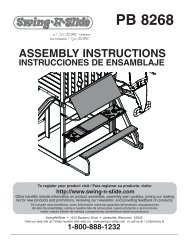
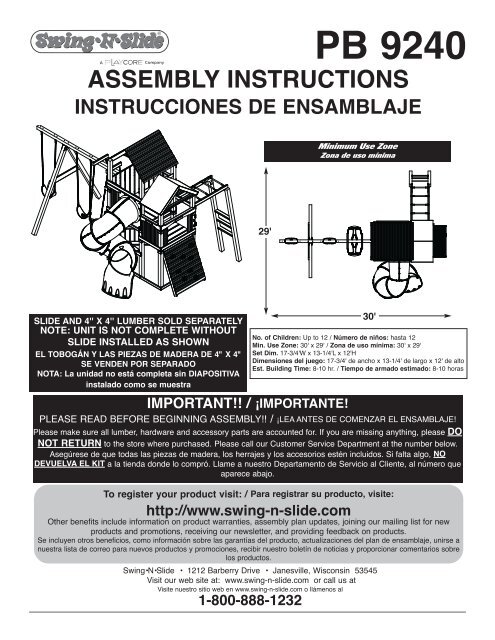
PB 9240<br />
ASSEMBLY INSTRUCTIONS<br />
INSTRUCCIONES DE ENSAMBLAJE<br />
Minimum Use Zone<br />
Zona <strong>de</strong> uso mínima<br />
29'<br />
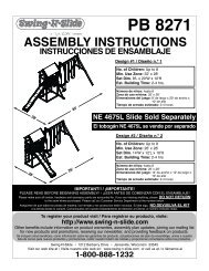
SLIDE AND 4'' X 4'' LUMBER SOLD SEPARATELY<br />
NOTE: UNIT IS NOT COMPLETE WITHOUT<br />
SLIDE INSTALLED AS SHOWN<br />
EL TOBOGÁN Y LAS PIEZAS DE MADERA DE 4" X 4"<br />
SE VENDEN POR SEPARADO<br />
NOTA: La unidad no está completa sin DIAPOSITIVA<br />
instalado como se muestra<br />
30'<br />
No. of Children: Up to 12 / Número <strong>de</strong> niños: hasta 12<br />
Min. Use Zone: 30' x 29' / Zona <strong>de</strong> uso mínima: 30' x 29'<br />
Set Dim. 17-3/4'W x 13-1/4'L x 12'H<br />
Dimensiones <strong>de</strong>l juego: 17-3/4' <strong>de</strong> ancho x 13-1/4' <strong>de</strong> largo x 12' <strong>de</strong> alto<br />
Est. Building Time: 8-10 hr. / Tiempo <strong>de</strong> armado estimado: 8-10 horas<br />
IMPORTANT!! / ¡IMPORTANTE!<br />
PLEASE READ BEFORE BEGINNING ASSEMBLY!! / ¡LEA ANTES DE COMENZAR EL ENSAMBLAJE!<br />
Please make sure all lumber, hardware and accessory parts are accounted for. If you are missing anything, please DO<br />
NOT RETURN to the store where purchased. Please call our Customer Service Department at the number below.<br />
Asegúrese <strong>de</strong> que todas las piezas <strong>de</strong> ma<strong>de</strong>ra, los herrajes y los accesorios estén incluidos. Si falta algo, NO<br />
DEVUELVA EL KIT a la tienda don<strong>de</strong> lo compró. Llame a nuestro Departamento <strong>de</strong> Servicio al Cliente, al número que<br />
aparece abajo.<br />
To register your product visit: / Para registrar su producto, visite:<br />
http://www.swing-n-sli<strong>de</strong>.com<br />
Other benefits inclu<strong>de</strong> information on product warranties, assembly plan updates, joining our mailing list for new<br />
products and promotions, receiving our newsletter, and providing feedback on products.<br />
Se incluyen otros beneficios, como información sobre las garantías <strong>de</strong>l producto, actualizaciones <strong>de</strong>l plan <strong>de</strong> <strong>ensamblaje</strong>, unirse a<br />
nuestra lista <strong>de</strong> correo para nuevos productos y promociones, recibir nuestro boletín <strong>de</strong> noticias y proporcionar comentarios sobre<br />
los productos.<br />
<strong>Swing</strong>•N•Sli<strong>de</strong> • 1212 Barberry Drive • Janesville, Wisconsin 53545<br />
Visit our web site at: www.swing-n-sli<strong>de</strong>.com or call us at<br />
Visite nuestro sitio web en www.swing-n-sli<strong>de</strong>.com o llámenos al<br />
1-800-888-1232
Safety Checklist for <strong>Swing</strong>-N-Sli<strong>de</strong> Play Sets and Accessories<br />
Observing the following statements and warnings reduces the likelihood of serious or fatal injury<br />
Installation Safety – Have You:<br />
Consulted the assembly instructions supplied with your particular mo<strong>de</strong>l?<br />
Noted this accessory is to be used only on <strong>Swing</strong>•N•Sli<strong>de</strong> approved <strong>de</strong>signs? (Do not alter its <strong>de</strong>sign or add/remove components.)<br />
Ma<strong>de</strong> sure all hardware is tightened securely? (Supplied bolt covers must also be fastened securely.)<br />
Using a hacksaw, cut off all protruding threa<strong>de</strong>d ends of bolts and other fasteners and remove any sharp edges with<br />
a metal file as nee<strong>de</strong>d, and coated fastener ends with lead free paint?<br />
Placed the equipment on level ground, not less than six feet (1.8 meters) from any structure or obstruction such as a fence, garage,<br />
house, overhanging branches, laundry lines, or electrical wires?<br />
Ma<strong>de</strong> sure home playground equipment is not installed over concrete, asphalt, packed earth or any other hard surface? (A fall onto<br />
a hard surface can result in serious injury to the equipment user.)<br />
Verified that suspen<strong>de</strong>d climbing ropes, chain,or cable are securely anchored at both ends and cannot be looped back unpon itself?<br />
Consulted in assembly instructions of your particular mo<strong>de</strong>l for minimum use zones?<br />
Used a water sealant on your play set to protect the wood and prevent cracking and warping?<br />
Followed all anchoring and shock absorbing surfacing requirements on the back of this sheet as they apply?<br />
Ma<strong>de</strong> sure not to allow children to use equipment until it is properly installed?<br />
Ma<strong>de</strong> sure to adjust all swings so there is a minimum 8'' clearance between the swing and the ground surface?<br />
Operating Safety – Have You:<br />
Determined that on-site adult supervision is provi<strong>de</strong>d for children of all ages?<br />
Warned children the following before allowing them to use the equipment?<br />
Not to walk close to, in front of, behind or between moving items.<br />
Not to twist swing or any other accessory chains or ropes or loop them over the top support bar since this will reduce the<br />
strength of chain or rope.<br />
Not to swing empty seats or other accessories.<br />
Not to sli<strong>de</strong> down swing chains.<br />
Be sure to sit in the center of the swing seat and other accessories with full weight on the seat.<br />
Not to attach items to the playground equipment that are not specifically <strong>de</strong>signed for use with the equipment such as but not<br />
limited to, jump ropes, clotheslines, pet leashes, cables and chain. They may cause a strangulation hazard.<br />
Not to climb or walk on the top of swing beams, railings or roof.<br />
Not to use equipment in a manner other than inten<strong>de</strong>d.<br />
Not to get off equipment while it is in motion.<br />
Not to climb on the equipment when it is wet.<br />
Be sure to go down sli<strong>de</strong>s feet first.<br />
Determined that only one child per planned occupant seat should be allowed on this set at one time.<br />
Determined children must be dressed appropriately for play. Avoid hoo<strong>de</strong>d jackets, bicycle or other sports helmets, clothing with<br />
draw strings and loose fitting clothes which could become entangled or snagged on equipment.<br />
Determined that suspen<strong>de</strong>d climbing ropes, chain, or cable are securely anchored at both ends and cannot be looped back upon<br />
itself.<br />
Ma<strong>de</strong> certain the sli<strong>de</strong> is placed so that is is not in direct sunlight.<br />
Safety Maintenance – Follow these preventive maintenance instructions at the intervals required:<br />
To prevent the <strong>de</strong>terioration of materials, remove plastic swing seats and other plastic accessories when outdoors temp dips down to<br />
or below 32° F and take indoors. Reinstall these plastic elements at the beginning of each play season.<br />
At the beginning of each play season check metal parts for rust. If found, sand and repaint using a non lead-based paint meeting the<br />
requirements of 16 CFR 1303 or SOR/2005-109.<br />
At the beginning of each play season and once a month during each play season, check all moving parts for wear, rust or other<br />
<strong>de</strong>terioration. Replace as nee<strong>de</strong>d. If any of these conditions exist, call 1-800-888-1232 to or<strong>de</strong>r replacement accessories.<br />
At the beginning of each play season and once a month during each play season lubricate metallic moving parts.<br />
At the beginning of each play season and twice a month during each play season, check all protective coverings on bolts, pipes,<br />
edges, and corners. Replace if they are loose, cracked, or missing.<br />
At the beginning of each play season and twice a month during each play season, rake and check <strong>de</strong>pth of loose fill protective<br />
surfacing material to prevent compaction and maintain appropriate <strong>de</strong>pth. Replace as necessary.<br />
At the beginning of each play season and twice a month during each play season tighten all hardware.<br />
At the beginning of each play season and twice a month during each play season, check all wood members for <strong>de</strong>terioration and<br />
splinters. Sand down splinters and replace <strong>de</strong>teriorating wood members.<br />
Disposal <strong>Instructions</strong><br />
When the equipment is taken out of service, it must be disassembled and disposed of in such a way that no unreasonable hazards will exist at<br />
the time the set is discar<strong>de</strong>d.<br />
Important! Additional Safety <strong>Instructions</strong> for all <strong>Swing</strong>-N-Sli<strong>de</strong> Playground Equipment.<br />
Save this instruction sheet in the event the manufacturer needs to be contacted.<br />
2
This product is inten<strong>de</strong>d for single family home/resi<strong>de</strong>ntial use only and not inten<strong>de</strong>d for use in any public setting.<br />
Placement in any public setting constitutes a misuse of this product.<br />
IMPORTANT!<br />
ADDITIONAL REQUIRED SAFETY INSTALLATION INSTRUCTIONS<br />
According to ASTM requirements, all kits must be anchored to the ground and, if the unit has a climbing rope, the rope end must be anchored to the ground. If soil conditions<br />
permit stakes to be pulled out easily, cementing into ground is necessary.<br />
• To anchor the unit to the ground, Follow the instructions inclu<strong>de</strong>d in this plan for applying Anchor-It <strong>de</strong>vices to your unit, or use 2" x 4" x 18" (45mm x 95mm x 457mm) pressuretreated<br />
stakes. Pound stakes into ground at least 12" (305mm) at all insi<strong>de</strong> corners of the posts (including A-frame legs and climbing unit posts). Attach with four (4) 16D (3-1/2")<br />
galvanized nails per stake into each tower and/or A-frame upright.<br />
• If the unit has a climbing rope, securely anchor the rope at both ends.<br />
• Once the unit is completely assembled and before children are allowed to play on it, proper shock-absorbing surfacing material must be installed. This may be accomplished by<br />
using loose-fill materials at a sufficient <strong>de</strong>pth. The Consumer Product Safety Commission “Handbook for Public Playground Safety” lists the following materials and required<br />
<strong>de</strong>pths that are sufficient for home/resi<strong>de</strong>ntial application. Supplemental information may be found in ASTM F1292. For fall height protection up to 9 ft. (2.742m) [recommen<strong>de</strong>d<br />
for <strong>Swing</strong>•N•Sli<strong>de</strong> kits]:<br />
LOOSE FILL MATERIAL<br />
Wood Mulch<br />
Double Shred<strong>de</strong>d Bark Mulch<br />
Uniform Wood Chips<br />
REQUIRED (UNCOMPRESSED) DEPTH 1 in. (mm)<br />
9" (229mm)<br />
9" (229mm)<br />
12" (305mm)<br />
These <strong>de</strong>pths were <strong>de</strong>rived from the CPSC Handbook. <strong>Swing</strong>•N•Sli<strong>de</strong> has not done in<strong>de</strong>pen<strong>de</strong>nt tests to <strong>de</strong>termine these required <strong>de</strong>pths.<br />
When properly installed, shock absorbing material will completely cover the horizontal baseboards on climbing units. This protective surfacing must extend a minimum of 6 ft.<br />
(1.828m) in all directions from the perimeter of the equipment or from the outermost edges of any component. For example, a sli<strong>de</strong> extending beyond the platform must have<br />
protective surfacing at least 6 ft. (1.828mm) out from both si<strong>de</strong>s as well as the end. For swings, the protective surface must extend at least 14 ft. (6m) out from both the back and<br />
front of the swing when the swing is in its rest position.<br />
For further information on playground safety, the Consumer Product Safety Commission<br />
(CPSC) publishes the Outdoor Home Playground Safety Handbook which can be downloa<strong>de</strong>d for free<br />
from www.cpsc.gov. An additional resource is the American Society of Testing and Materials (ASTM)<br />
Standard Consumer Safety Performance Specification for Home Playground Equipment (ASTM F1148)<br />
which can be purchased and downloa<strong>de</strong>d from www.astm.org.<br />
<strong>Swing</strong>-N-Sli<strong>de</strong>® MANUFACTURERS LIMITED WARRANTY<br />
<strong>Swing</strong>-N-Sli<strong>de</strong>® takes great pri<strong>de</strong> in the quality and durability of our products. Our Manufacturer’s Limited Warranty provi<strong>de</strong>s confi<strong>de</strong>nce and <strong>de</strong>monstrates our commitment<br />
to providing quality resi<strong>de</strong>ntial playground products.<br />
MANUFACTURER’S LIFETIME LIMITED WARRANTY<br />
<strong>Swing</strong>-N-Sli<strong>de</strong>® warrants its thermoformed sli<strong>de</strong>s and climbing mountains to be free from <strong>de</strong>fects in workmanship and materials, un<strong>de</strong>r normal use and conditions, for the<br />
lifetime of the product.<br />
MANUFACTURER’S 5 YEAR LIMITED WARRANTY<br />
<strong>Swing</strong>-N-Sli<strong>de</strong>® warrants its Custom Ready-to-Build Play Set kits and accessories to be free from <strong>de</strong>fects in workmanship and materials, un<strong>de</strong>r normal use and conditions,<br />
for a period of 5 years.<br />
MANUFACTURER’S 5 YEAR LIMITED WARRANTY<br />
<strong>Swing</strong>-N-Sli<strong>de</strong>® warrants its No-Cut and Wood Complete Ready-to-Assemble Play Set kits against wood rot and termite damage, and to be free from <strong>de</strong>fects in<br />
workmanship and materials, un<strong>de</strong>r normal use and conditions, for a period of 5 years for structural wood components.<br />
Cosmetic <strong>de</strong>fects that do not affect the structural integrity of the product, or natural <strong>de</strong>fects of wood such as warping, splitting, checking, twisting, shrinkage, swelling or<br />
any other physical properties of wood that do not present a safety hazard, are not covered by this warranty.<br />
MANUFACTURER’S ONE YEAR WARRANTY<br />
<strong>Swing</strong>-N-Sli<strong>de</strong>® warrants its canopy roofs and/or tarps, and Timber GLOVE lumber wrap to be free from <strong>de</strong>fects in workmanship and materials, un<strong>de</strong>r normal use and<br />
conditions, for a period of one year.<br />
<strong>Swing</strong>-N-Sli<strong>de</strong>® will repair, or at its discretion, replace any part within the stated warranty period which is <strong>de</strong>fective in workmanship or materials. This <strong>de</strong>cision is subject<br />
to verification of the <strong>de</strong>fect upon <strong>de</strong>livery of the <strong>de</strong>fective part to <strong>Swing</strong>-N-Sli<strong>de</strong>® at 1212 Barberry Drive, Janesville, Wisconsin, 53545. Any part(s) returned to <strong>Swing</strong>-N-<br />
Sli<strong>de</strong>® must have prior approved Return Authorization Number and proof of purchase, including the date of purchase. This warranty is valid only if the product is used for<br />
the purpose for which it was <strong>de</strong>signed and installed at a resi<strong>de</strong>ntial, single family dwelling. This warranty is void if the product is put to commercial or institutional use. This<br />
warranty does not cover (a) products which have been damaged by acts of Nature, negligence, misuse, or acci<strong>de</strong>nt, or which have been modified or repaired by<br />
unauthorized persons; (b) the cost of labor; or the cost of shipping the product, any part, or any replacement product or part.<br />
<strong>Swing</strong>-N-Sli<strong>de</strong>® DISCLAIMS ALL OTHER REPRESENTATIONS AND WARRANTIES OF ANY KIND, EXPRESS, IMPLIED, STATUTORY OR OTHERWISE, INCLUDING THE<br />
IMPLIED WARRANTIES OF MERCHANTIBILITY AND FITNESS FOR A PARTICULAR PURPOSE. <strong>Swing</strong>-N-Sli<strong>de</strong>® WILL NOT BE LIABLE FOR ANY INCIDENTAL OR<br />
CONSEQUENTIAL DAMAGES. This warranty is non-transferable and does not extend to the owners of the product subsequent to the original purchaser. Some states do not<br />
allow limitations on implied warranties or exclusion of inci<strong>de</strong>ntal or consequential damages, so these restrictions may not be applicable to you. This warranty gives you<br />
specific legal rights. You may also have other rights, which vary from state to state.<br />
This warranty also does not apply to:<br />
• Structures not erected, maintained or inspected in conformance with <strong>Swing</strong>-N-Sli<strong>de</strong>® installation plans<br />
• Structures that have had parts ad<strong>de</strong>d or substituted not in conformance with <strong>Swing</strong>-N-Sli<strong>de</strong>® installation plans<br />
• Parts that have been modified, altered or misused<br />
• Parts that have not been used as <strong>de</strong>signed or inten<strong>de</strong>d<br />
• Damage due to acts of Nature, vandalism, abnormal use or abuse as <strong>de</strong>termined by <strong>Swing</strong>-N-Sli<strong>de</strong>®<br />
3
Seguridad durante la instalación – Usted:<br />
¿Ha consultado las instrucciones <strong>de</strong> <strong>ensamblaje</strong> suministradas con su mo<strong>de</strong>lo en particular?<br />
¿Ha notado que este accesorio se <strong>de</strong>be usar solamente con diseños aprobados por <strong>Swing</strong>•N•Sli<strong>de</strong>? (No altere su diseño ni añada/retire componentes).<br />
¿Se ha asegurado <strong>de</strong> que todos los accesorios hayan sido ajustados firmemente? (Las cubiertas <strong>de</strong> los pernos suministradas también se <strong>de</strong>ben<br />
asegurar firmemente).<br />
¿Se ha asegurado <strong>de</strong> cortar con una sierra <strong>de</strong> mano todos los extremos roscados sobresalientes <strong>de</strong> los pernos y <strong>de</strong>más sujetadores, así como <strong>de</strong> haber eliminado<br />
cualquier bor<strong>de</strong> filoso usando una lima para metales, según haya sido necesario, y recubierto los extremos <strong>de</strong> los sujetadores con pintura sin plomo?<br />
¿Ha colocado el equipo a nivel <strong>de</strong>l piso, a no menos <strong>de</strong> seis pies (1.8 metros) <strong>de</strong> cualquier estructura u obstrucción tal como una cerca, garaje, casa,<br />
ramas colgantes, sogas para ten<strong>de</strong>r la ropa o cables eléctricos?<br />
¿Se ha asegurado <strong>de</strong> que el equipo <strong>de</strong> juego no haya sido instalado sobre concreto, asfalto, tierra prensada o cualquier otra superficie dura?<br />
(Una caída sobre una superficie dura pue<strong>de</strong> provocar una lesión grave al usuario <strong>de</strong>l equipo).<br />
¿Ha verificado que las cuerdas para escalar, la ca<strong>de</strong>na o el cable suspendidos estén sujetados en ambos extremos?<br />
¿Ha consultado las zonas mínimas <strong>de</strong> uso en las instrucciones <strong>de</strong> <strong>ensamblaje</strong> <strong>de</strong> su mo<strong>de</strong>lo en particular?<br />
¿Ha usado un sellador <strong>de</strong> agua en su conjunto <strong>de</strong> juego para proteger la ma<strong>de</strong>ra y prevenir que se agriete y se tuerza?<br />
¿Ha seguido todos los requisitos que se encuentran en el reverso <strong>de</strong> esta página relacionados con el anclaje y el recubrimiento amortiguador <strong>de</strong> golpes,<br />
según corresponda?<br />
¿Se ha asegurado <strong>de</strong> no permitir que los niños usen los equipos hasta que éstos que<strong>de</strong>n correctamente instalados?<br />
¿Se ha asegurado <strong>de</strong> ajustar todos los columpios <strong>de</strong> manera que haya un espacio mínimo <strong>de</strong> 8'' entre el columpio y la superficie <strong>de</strong>l suelo?<br />
Seguridad durante la operación – Usted:<br />
¿Se ha asegurado <strong>de</strong> que en el sitio <strong>de</strong> juegos haya supervisión por parte <strong>de</strong> un adulto para los niños <strong>de</strong> todas las eda<strong>de</strong>s?<br />
Antes <strong>de</strong> permitirles usar los equipos, ¿les ha enseñado a los niños lo siguiente? No caminar cerca, enfrente, por <strong>de</strong>trás o entre objetos móviles.<br />
No retorcer el columpio ni cualquiera <strong>de</strong> las ca<strong>de</strong>nas o cuerdas accesorias ni enrollarlas sobre la barra <strong>de</strong> soporte superior, ya que esto reduciría la<br />
fuerza <strong>de</strong> la ca<strong>de</strong>na o la cuerda.<br />
No columpiar los asientos vacíos u otros accesorios.<br />
No <strong>de</strong>slizarse hacia abajo por las ca<strong>de</strong>nas <strong>de</strong> los columpios.<br />
Asegurarse <strong>de</strong> sentarse en el centro <strong>de</strong>l columpio y en los otros accesorios, con todo el peso sobre el asiento.<br />
No unir accesorios al equipo <strong>de</strong> juego que no estén diseñados específicamente para el mismo, como los siguientes, entre otros: cuerdas para saltar,<br />
sogas para ten<strong>de</strong>r la ropa, correas para mascotas, cables y ca<strong>de</strong>nas. Éstos pue<strong>de</strong>n provocar peligro <strong>de</strong> estrangulamiento.<br />
No trepar ni caminar sobre la parte superior <strong>de</strong> las vigas <strong>de</strong> los columpios, los pasamanos o el techo.<br />
No usar los equipos <strong>de</strong> manera diferente a aquella para la cual fueron diseñados.<br />
No saltar <strong>de</strong> los equipos cuando están en movimiento.<br />
No subirse a los equipos cuando estén mojados.<br />
Asegurarse <strong>de</strong> bajar por los toboganes con los pies por <strong>de</strong>lante.<br />
¿Ha <strong>de</strong>terminado que sólo se pue<strong>de</strong> permitir un niño por asiento en un mismo momento?<br />
¿Has <strong>de</strong>terminado que los niños <strong>de</strong>ben estar vestidos en forma a<strong>de</strong>cuada para el juego? Evita chaquetas con capucha, cascos para bicicletas u otros<br />
<strong>de</strong>portes, ropa con cordones y suelta que podría hacer que se enre<strong>de</strong>n o se enganchen en el equipo.<br />
¿Has <strong>de</strong>terminado que las sogas, ca<strong>de</strong>nas o cables para escalar están anclados firmemente en ambos extremos y no pue<strong>de</strong>n entrelazarse?<br />
¿Se ha asegurado <strong>de</strong> que el tobogán se ubique <strong>de</strong> manera que no esté bajo la luz directa <strong>de</strong>l sol?<br />
Mantenimiento <strong>de</strong> Seguridad–Sigue estas instrucciones preventivas <strong>de</strong> mantenimiento en los intervalos<br />
requeridos:<br />
Para evitar el <strong>de</strong>terioro <strong>de</strong> los materiales, retira los asientos <strong>de</strong> plástico <strong>de</strong> los columpios y otros accesorios <strong>de</strong> plástico cuando la temperatura exterior<br />
baje a 32° F o menos y llévalos a un lugar bajo techado. Reinstala estos elementos plásticos al inicio <strong>de</strong> cada temporada <strong>de</strong> juego.<br />
Al inicio <strong>de</strong> cada temporada <strong>de</strong> juego verifica que las piezas <strong>de</strong> metal no se hayan oxidado. Si se encuentran indicios <strong>de</strong> corrosión, lija y vuelve a pintar<br />
usando una pintura que no sea a base <strong>de</strong> plomo y que cumpla con los requisitos 16 CFR 1303 o SOR/2005-109.<br />
Al inicio <strong>de</strong> cada temporada <strong>de</strong> juego y una vez al mes durante la misma, verifica que las piezas movibles no se hayan <strong>de</strong>sgastado, oxidado o<br />
<strong>de</strong>teriorado <strong>de</strong> otra manera. Reemplázala si es necesario. Si existe alguna <strong>de</strong> estas condiciones, llama al 1-800-888-1232 para or<strong>de</strong>nar los accesorios <strong>de</strong><br />
repuesto.<br />
Al inicio <strong>de</strong> cada temporada <strong>de</strong> juego y una vez al mes durante la misma, lubrica las piezas <strong>de</strong> metal en movimiento.<br />
Al inicio <strong>de</strong> cada temporada <strong>de</strong> juego y dos veces al mes durante la misma, revisa todas las cubiertas protectores <strong>de</strong> pernos, tubos, bor<strong>de</strong>s y esquinas.<br />
Reemplázalas si están sueltas, rotas o si faltan.<br />
Al inicio <strong>de</strong> cada temporada <strong>de</strong> juego y dos veces al mes durante la misma, rastrilla y verifica la profundidad <strong>de</strong>l material protector <strong>de</strong> relleno <strong>de</strong> superficies<br />
para que no esté flojo, evitar la compactación y mantener la profundidad a<strong>de</strong>cuada. Reemplaza según sea necesario.<br />
Al inicio <strong>de</strong> cada temporada <strong>de</strong> juego y dos veces al mes durante la misma, ajusta todos los herrajes.<br />
Al inicio <strong>de</strong> cada temporada <strong>de</strong> juego y una vez al mes durante misma, verifica que las piezas <strong>de</strong> ma<strong>de</strong>ra no estén <strong>de</strong>terioradas y astilladas. Lija las<br />
astilladuras y reemplaza las partes <strong>de</strong> ma<strong>de</strong>ra <strong>de</strong>terioradas.<br />
<strong>Instrucciones</strong> <strong>de</strong> <strong>de</strong>secho<br />
Lista <strong>de</strong> control <strong>de</strong> seguridad para los juegos y accesorios <strong>Swing</strong>-N-Sli<strong>de</strong><br />
Aten<strong>de</strong>r los siguientes enunciados y advertencias reduce la posibilidad <strong>de</strong> lesiones graves o fatales.<br />
Cuando el equipo sea retirado <strong>de</strong> servicio, se <strong>de</strong>be <strong>de</strong>sarmar y <strong>de</strong>sechar <strong>de</strong> tal manera que no presente peligros no razonables al momento <strong>de</strong> <strong>de</strong>secharlo.<br />
¡Importante! <strong>Instrucciones</strong> <strong>de</strong> seguridad adicionales para todos los equipos <strong>de</strong> juego <strong>Swing</strong>-N-Sli<strong>de</strong>.<br />
Guardar esta hoja <strong>de</strong> instrucciones en caso <strong>de</strong> que se requiera contactar al fabricante.<br />
4
Este producto ha sido i<strong>de</strong>ado para su uso en una resi<strong>de</strong>ncia u hogar <strong>de</strong> una sola familia y no para usarse en lugares públicos.<br />
Su uso en lugares públicos constituye una mala utilización <strong>de</strong> este producto.<br />
¡IMPORTANTE!<br />
INSTRUCCIONES ADICIONALES DE SEGURIDAD PARA LA INSTALACIÓN<br />
Según establece la Sociedad Americana <strong>de</strong> Pruebas y Materiales (American Society for Testing and Materials, ASTM), todos los equipos <strong>de</strong>ben anclarse al suelo y, si la unidad tiene a<strong>de</strong>más una cuerda<br />
para escalar, el extremo <strong>de</strong> la cuerda <strong>de</strong>berá anclarse al suelo. Si las condiciones <strong>de</strong>l terreno permiten que las estacas se salgan con facilidad, será entonces necesario cementarlas al suelo.<br />
• Para anclar la unidad al suelo, siga las instrucciones contenidas en el presente plan para aplicar los dispositivos <strong>de</strong> anclaje a su unidad, o utilice estacas tratadas a presión <strong>de</strong> 2" x 4" x<br />
18"(45mm x 95mm x 457mm). Martille las estacas en el suelo a una profundidad <strong>de</strong> al menos 12" (305 mm) en todas las esquinas internas <strong>de</strong> los postes (incluidas las patas <strong>de</strong>l marco en A y<br />
los postes <strong>de</strong> la unidad para escalar). Fije con cuatro (4) clavos galvanizados <strong>de</strong> 16D (3-1/2") por estaca en cada poste <strong>de</strong> la torre y/o <strong>de</strong>l marco en “A”.<br />
• Si la unidad incluye una soga para escalar, ancla la soga en ambos extremos.<br />
• Una vez que la unidad esté completamente armada y antes <strong>de</strong> que se le permita a los niños jugar en ella, se <strong>de</strong>be instalar una superficie <strong>de</strong> material a<strong>de</strong>cuado para<br />
amortiguar golpes. Esto se consigue usando materiales <strong>de</strong> relleno suelto a una profundidad a<strong>de</strong>cuada. La “Guía para la seguridad en las zonas <strong>de</strong> recreo públicas” (Handbook for Public<br />
Playground Safety) publicada por la Comisión <strong>de</strong> Seguridad para los Productos <strong>de</strong> Consumo (Consumer Product Safety Commission, CPSC) cita los siguientes materiales y las profundida<strong>de</strong>s<br />
requeridas que se consi<strong>de</strong>ran suficientes para uso en resi<strong>de</strong>ncias y hogares. Información adicional pue<strong>de</strong> encontrarse en ASTM F1292.Para protegerse <strong>de</strong> caídas <strong>de</strong> hasta 9 pies (2.742m) <strong>de</strong><br />
altura [recomendado para los equipos <strong>Swing</strong>•N•Sli<strong>de</strong>]:<br />
MATERIALES DE RELLENO SUELTO<br />
Mantillo <strong>de</strong> ma<strong>de</strong>ra<br />
Mantillo <strong>de</strong> corteza <strong>de</strong> doble trituración<br />
Viruta <strong>de</strong> ma<strong>de</strong>ra uniforme<br />
PROFUNDIDAD (SIN COMPRIMIR) REQUERIDA 1 pulgada (mm)<br />
9" (229 mm)<br />
9" (229 mm)<br />
12" (305 mm)<br />
Estas profundida<strong>de</strong>s se han extraído <strong>de</strong> la Guía <strong>de</strong> la CPSC. <strong>Swing</strong>•N•Sli<strong>de</strong> no ha realizado estudios in<strong>de</strong>pendientes para <strong>de</strong>terminar estas profundida<strong>de</strong>s recomendadas.<br />
Cuando el material para amortiguar golpes se instala a<strong>de</strong>cuadamente, éste cubre completamente todas las superficies horizontales <strong>de</strong> las unida<strong>de</strong>s para escalar. Esta superficie protectora<br />
<strong>de</strong>berá exten<strong>de</strong>rse al menos 6 pies (1.828mm) en todas las direcciones, <strong>de</strong>s<strong>de</strong> el perímetro <strong>de</strong>l equipo o <strong>de</strong>s<strong>de</strong> los bor<strong>de</strong>s externos <strong>de</strong> cualquiera <strong>de</strong> los componentes. Por ejemplo, un<br />
tobogán que se extien<strong>de</strong> por fuera <strong>de</strong> la plataforma <strong>de</strong>berá tener una superficie protectora <strong>de</strong> al menos 6 pies (1.828mm) a ambos lados y en el extremo. Para columpios, la superficie<br />
protectora se <strong>de</strong>be exten<strong>de</strong>r por lo menos 14 pies (6 m) a partir <strong>de</strong> tanto la parte trasera como <strong>de</strong>lantera <strong>de</strong>l columpio cuando éste se encuentre en posición <strong>de</strong> reposo.<br />
Para obtener información adicional sobre seguridad en las zonas <strong>de</strong> recreo, la Comisión <strong>de</strong> Seguridad para los Productos <strong>de</strong><br />
Consumo (Consumer Product Safety Commission, CPSC) publica el Manual para la seguridad en las zonas <strong>de</strong> recreo domésticas al aire<br />
libre (Outdoor Home Playground Safety Handbook) que se pue<strong>de</strong> <strong>de</strong>scargar en forma gratuita <strong>de</strong> www.cpsc.gov. Un recurso adicional es la<br />
Especificación Estándar <strong>de</strong> Rendimiento <strong>de</strong> la Seguridad <strong>de</strong>l Consumidor <strong>de</strong> la Sociedad <strong>de</strong> EE. UU. <strong>de</strong> Pruebas y Materiales (ASTM)<br />
Para Equipos <strong>de</strong> Patios <strong>de</strong> Recreo en el Hogar (ASTM F1148) que se pue<strong>de</strong> adquirir y <strong>de</strong>scargar en www.astm.org.<br />
GARANTÍA LIMITADA DEL FABRICANTE DE <strong>Swing</strong>-N-Sli<strong>de</strong> ®<br />
<strong>Swing</strong>-N-Sli<strong>de</strong>® se enorgullece <strong>de</strong> la calidad y la durabilidad <strong>de</strong> nuestros productos. Nuestra garantía limitada <strong>de</strong>l fabricante ofrece confianza y <strong>de</strong>muestra<br />
nuestro compromiso con la entrega <strong>de</strong> productos <strong>de</strong> calidad para zonas <strong>de</strong> recreo resi<strong>de</strong>nciales.<br />
GARANTÍA LIMITADA DE POR VIDA DEL FABRICANTE<br />
<strong>Swing</strong>-N-Sli<strong>de</strong>® garantiza que sus toboganes termoformados y montañas para escalar estarán libres <strong>de</strong> <strong>de</strong>fectos <strong>de</strong> mano <strong>de</strong> obra y materiales, bajo condiciones y<br />
uso normales, durante la vida útil <strong>de</strong>l producto.<br />
GARANTÍA LIMITADA DE 5 AÑOS DEL FABRICANTE<br />
<strong>Swing</strong>-N-Sli<strong>de</strong>® garantiza que sus kits <strong>de</strong> conjunto <strong>de</strong> juegos personalizados listos para armar y sus accesorios permanecerán libres <strong>de</strong> <strong>de</strong>fectos <strong>de</strong> mano <strong>de</strong><br />
obra y materiales, bajo condiciones y uso normales, durante un período <strong>de</strong> 5 años.<br />
GARANTÍA LIMITADA DE 5 AÑOS DEL FABRICANTE<br />
<strong>Swing</strong>-N-Sli<strong>de</strong>® garantiza que sus kits <strong>de</strong> conjunto <strong>de</strong> juegos No-Cut and Wood Complete Ready-to-Assemble Play Set no experimentarán <strong>de</strong>terioro <strong>de</strong>bido<br />
a putrefacción <strong>de</strong> la ma<strong>de</strong>ra o termitas, y que permanecerán libres <strong>de</strong> <strong>de</strong>fectos <strong>de</strong> mano <strong>de</strong> obra y materiales, bajo condiciones y uso normales, durante un<br />
período <strong>de</strong> 5 años en el caso <strong>de</strong> los componentes estructurales <strong>de</strong> ma<strong>de</strong>ra.<br />
Los <strong>de</strong>fectos estéticos que no afecten la integridad estructural <strong>de</strong>l producto o los <strong>de</strong>fectos naturales <strong>de</strong> la ma<strong>de</strong>ra como la torsión, la rajadura, la fisuración, el<br />
pan<strong>de</strong>o, contracción, hinchamiento o cualquier otra propiedad física <strong>de</strong> la ma<strong>de</strong>ra que no presente un riesgo <strong>de</strong> seguridad, no están cubiertos por esta garantía.<br />
GARANTÍA DE UN AÑO DEL FABRICANTE<br />
<strong>Swing</strong>-N-Sli<strong>de</strong>® garantiza que sus techos y/o lonas impermeabilizadas <strong>de</strong> cubierta y envoltura para ma<strong>de</strong>ra Timber-GLOVE permanecerán libres <strong>de</strong> <strong>de</strong>fectos <strong>de</strong><br />
mano <strong>de</strong> obra y materiales, bajo condiciones y uso normales, durante un período <strong>de</strong> un año.<br />
<strong>Swing</strong>-N-Sli<strong>de</strong>® reparará, o según su criterio, reemplazará, <strong>de</strong>ntro <strong>de</strong>l período <strong>de</strong> garantía señalado, cualquier pieza que presente <strong>de</strong>fectos <strong>de</strong> mano <strong>de</strong> obra o<br />
materiales. Esta <strong>de</strong>cisión está sujeta a verificación <strong>de</strong>l <strong>de</strong>fecto luego <strong>de</strong>l envío <strong>de</strong> la pieza <strong>de</strong>fectuosa a <strong>Swing</strong>-N-Sli<strong>de</strong>® a 1212 Barberry Drive, Janesville,<br />
Wisconsin, 53545. Toda pieza <strong>de</strong>vuelta a <strong>Swing</strong>-N-Sli<strong>de</strong>® primero <strong>de</strong>be tener un Número <strong>de</strong> autorización <strong>de</strong> <strong>de</strong>volución aprobado y una prueba <strong>de</strong> compra,<br />
incluida la fecha <strong>de</strong> compra. Esta garantía es válida sólo si el producto se utiliza para el objetivo que se diseñó y se instala en una vivienda unifamiliar resi<strong>de</strong>ncial.<br />
Esta garantía queda nula si al producto se le da un uso comercial o institucional. Esta garantía no cubre (a) productos que hayan sido dañados por hechos <strong>de</strong> la<br />
naturaleza, negligencia, uso in<strong>de</strong>bido o acci<strong>de</strong>nte, o que hayan sido modificados o reparados por personas no autorizadas; (b) el costo <strong>de</strong> la mano <strong>de</strong> obra o el<br />
costo <strong>de</strong> envío <strong>de</strong>l producto, alguna pieza o un producto o pieza <strong>de</strong> reemplazo.<br />
<strong>Swing</strong>-N-Sli<strong>de</strong>® DESCONOCE TODAS LAS DEMÁS DECLARACIONES Y GARANTÍAS DE CUALQUIER TIPO, EXPRESAS, IMPLÍCITAS, ESTATUTARIAS U OTRAS,<br />
INCLUIDAS LAS GARANTÍAS IMPLÍCITAS DE COMERCIABILIDAD Y APTITUD PARA UN FIN ESPECÍFICO. <strong>Swing</strong>-N-Sli<strong>de</strong>® NO SERÁ RESPONSABLE DE NINGÚN DAÑO<br />
FORTUITO O CONSECUENTE. Esta garantía no es transferible y no se extien<strong>de</strong> a los propietarios <strong>de</strong>l producto posteriores al comprador original. Algunos estados<br />
no permiten limitaciones en las garantías implícitas ni la exclusión <strong>de</strong> daños fortuitos o consecuentes, por tanto es posible que estas restricciones no se apliquen<br />
en su caso. Esta garantía le otorga <strong>de</strong>rechos legales específicos. Es posible que tenga otros <strong>de</strong>rechos, que pue<strong>de</strong>n variar <strong>de</strong> un estado a otro.<br />
Esta garantía tampoco se aplica a:<br />
• Estructuras no levantadas, mantenidas ni inspeccionadas en conformidad con los planos <strong>de</strong> instalación <strong>de</strong> <strong>Swing</strong>-N-Sli<strong>de</strong>®<br />
• Estructuras en las que se ha agregado o sustituido piezas que no están en conformidad con los planos <strong>de</strong> instalación <strong>de</strong> <strong>Swing</strong>-N-Sli<strong>de</strong>®<br />
• Piezas que se han modificado, alterado o usado in<strong>de</strong>bidamente<br />
• Piezas que no se han usado según su diseño u objetivo<br />
• Daño <strong>de</strong>bido a hechos <strong>de</strong> la naturaleza, vandalismo, uso anormal o abuso según lo <strong>de</strong>termine <strong>Swing</strong>-N-Sli<strong>de</strong>®<br />
5
TOOLS REQUIRED / HERRAMIENTAS REQUERIDAS<br />
TOOLS REQUIRED / HERRAMIENTAS REQUERIDAS<br />
Utility Knife<br />
Navaja<br />
ELECTRIC DRILL<br />
TALADRO ELÉCTRICO<br />
HAMMER<br />
MARTILLO<br />
1/2" SOCKET & WRENCH<br />
LLAVE Y CUBO DE 1/2"<br />
WRENCH<br />
LLAVE INGLESA<br />
TAPE MEASURE<br />
CINTA MÉTRICA<br />
SAFETY GLASSES<br />
& DUST MASK<br />
GAFAS PROTECTORAS Y<br />
MÁSCARA ANTIPOLVO<br />
CARPENTER'S SQUARE<br />
ESCUADRA DE CARPINTERO<br />
PHILLIPS BIT<br />
PUNTA DE<br />
DESTORNILLADOR PHILLIPS<br />
1/8'' Drill Bit<br />
Broca <strong>de</strong> taladro <strong>de</strong> 1/8"<br />
(52) 2" lag screw<br />
tornillos <strong>de</strong> compresión <strong>de</strong> 2"<br />
(64) 1-1/4'' Lag Screw<br />
tornillos <strong>de</strong> compresión <strong>de</strong> 1-1/4''<br />
(7) 3'' Screws (NOT USED)<br />
Tornillos <strong>de</strong> 3'' (NO SE UTILIZA)<br />
(6) 3/4'' Panhead Screw<br />
tornillos <strong>de</strong> cabeza redonda<br />
aplanada <strong>de</strong> 3/4''<br />
(4) 1'' Truss Screw<br />
tornillos <strong>de</strong> cabeza redonda <strong>de</strong> 1''<br />
(24) 5/16'' Loc-Nuts<br />
tuercas <strong>de</strong> seguridad<br />
5/16''<br />
(320) 2-1/2'' screws<br />
tornillos <strong>de</strong> 2-1/2"<br />
(78) 2'' Wood Screw<br />
tornillos para ma<strong>de</strong>ra <strong>de</strong> 2''<br />
(40) 1-1/2'' screws<br />
tornillos <strong>de</strong> 1-1/2''<br />
(383) 30 mm screws<br />
tornillos <strong>de</strong> 30mm''<br />
(4) 1-1/2'' Lag Bolt<br />
pernos <strong>de</strong> compresión <strong>de</strong> 1-1/2"<br />
(4) 1-3/4'' panhead screws<br />
tornillos <strong>de</strong> cabeza redonda<br />
aplanada <strong>de</strong> 1-3/4''<br />
(2) 1/2'' panhead screws<br />
tornillos <strong>de</strong> cabeza<br />
redonda aplanada <strong>de</strong> 1/2"<br />
(2) Loc-Washe<br />
Aran<strong>de</strong>la <strong>de</strong> seguridad<br />
(4) 1/4'' flat washers<br />
aran<strong>de</strong>las planas<br />
<strong>de</strong> 1/4"<br />
(6) 3/16'' Tarp Washer<br />
Aran<strong>de</strong>la plana <strong>de</strong> 5/16''<br />
(28) 5/16'' flat washers<br />
aran<strong>de</strong>las planas <strong>de</strong> 5/16"<br />
(8) 5/16'' x 4-1/2'' Carriage Bolts<br />
pernos con cabeza <strong>de</strong> hongo <strong>de</strong> 5/16'' x 4-1/2"<br />
(2) 5/16'' x 4'' Carriage Bolts<br />
pernos con cabeza <strong>de</strong> hongo <strong>de</strong> 5/16'' x 4''<br />
(10) Wood Loc Washers<br />
aran<strong>de</strong>las <strong>de</strong> seguridad para<br />
ma<strong>de</strong>ra<br />
(2) 5/16'' x 6-1/4'' Hex Head Bolt / (2) pernos con cabeza hexagonal <strong>de</strong> 5/16'' x 6-1/4''<br />
6
R<br />
(2) 4'' x 4'' Shelf-Loc<br />
abraza<strong>de</strong>ras <strong>de</strong> estante <strong>de</strong> 4'' x 4''<br />
(1) LH Split Beam bracket<br />
abraza<strong>de</strong>ra <strong>de</strong> viga dividida<br />
izquierda<br />
(4) 23-1/4'' Monkey Bar Rungs<br />
peldaños <strong>de</strong> la barra trepadora <strong>de</strong> 23-1/4"<br />
(8) 2'' x 4'' Shelf-Loc<br />
abraza<strong>de</strong>ras <strong>de</strong> estante <strong>de</strong> 2'' x 4''<br />
(1) RH Split Beam bracket<br />
abraza<strong>de</strong>ra <strong>de</strong> viga dividida <strong>de</strong>recha<br />
(2) Roof Bracket<br />
abraza<strong>de</strong>ras <strong>de</strong> techo<br />
(1) Tarp<br />
(10) Wrap-Loc<br />
abraza<strong>de</strong>ras <strong>de</strong> envoltura<br />
(2) Boomerang Bracket<br />
abraza<strong>de</strong>ras tipo “Boomerang”<br />
(5) 10' Timber Glove<br />
Timber Glove <strong>de</strong> 10'<br />
(6) 8' Timber Glove<br />
Timber Glove <strong>de</strong> 8'<br />
(1) Tailor’s Chalk<br />
tiza <strong>de</strong> sastre<br />
(2) EZ Frame Brackets<br />
abraza<strong>de</strong>ras <strong>de</strong> la estructura EZ<br />
(1) 3/8" DRILL BIT (5'' Min.)<br />
BROCA DE TALADRO DE 3/8" (5" mín.)<br />
(1) T20 Torx® Bit<br />
broca T20 Torx®<br />
PB 9240<br />
Plan / Plano<br />
PB 9240<br />
INTENDED FOR USE BY CHILDREN<br />
FROM AGES 2-10 YEARS<br />
FOR HOME / RESIDENTIAL USE<br />
ONLY<br />
DISEÑADO PARA SER USADO POR<br />
NIÑOS ENTRE 2 Y 10 AÑOS DE<br />
EDAD PARA USO EN EL<br />
HOGAR/USO RESIDENCIAL<br />
ÚNICAMENTE<br />
RÉSERVÉ À L_UTILISATION PAR<br />
DES ENFANTS DE 2 À 10 ANS<br />
USAGE RÉSIDENTIEL/FAMILIAL<br />
SEULEMENT<br />
1212 Barberry Drive<br />
Janesville, WI 53545<br />
1-800-888-1232<br />
www.swing-n-sli<strong>de</strong>.com<br />
(1) T30 Torx® Bit<br />
broca T30 Torx®<br />
7<br />
(1) Plan<br />
plano<br />
(1) Name Plate<br />
placa <strong>de</strong> i<strong>de</strong>ntificación
<strong>Assembly</strong> <strong>Instructions</strong> / <strong>Instrucciones</strong> <strong>de</strong> <strong>ensamblaje</strong><br />
(4) Extra-Duty <strong>Swing</strong> Hangers<br />
colga<strong>de</strong>ros <strong>de</strong> columpio <strong>de</strong> alta<br />
resistencia<br />
(6) Step Brackets<br />
(Left)<br />
abraza<strong>de</strong>ras <strong>de</strong><br />
peldaño<br />
(izquierdas)<br />
(6) Step Brackets<br />
(Right)<br />
abraza<strong>de</strong>ras <strong>de</strong><br />
peldaño<br />
(<strong>de</strong>rechas)<br />
(2) 'L' Brackets<br />
abraza<strong>de</strong>ras en “L”<br />
(2) Safety Handles<br />
manijas <strong>de</strong> seguridad<br />
(4) Anchor-It<br />
anclajes<br />
(4) Anchor-It Straps<br />
correas <strong>de</strong> anclaje<br />
(8) Climbing Rocks<br />
piedras para escalar<br />
(8) 5/16'' x 2'' Carriage Bolts<br />
pernos con cabeza <strong>de</strong> hongo <strong>de</strong> 2''<br />
(16) Loc-Washer<br />
Aran<strong>de</strong>la <strong>de</strong> seguridad<br />
(16) Weld Nut<br />
(16) 8mm Washer<br />
aran<strong>de</strong>las planas <strong>de</strong> 8mm<br />
(2) RH Beam Bracket<br />
(2) Soportes RH<br />
(2) LH Beam Bracket<br />
(2) Soportes LH<br />
(4) BoltCovers<br />
(4) Tapas <strong>de</strong> perno (4) 4-1/4'' <strong>Swing</strong><br />
(2) 137-1/2'' Chain<br />
Hangers<br />
(2)Ca<strong>de</strong>na sin recubrimiento<br />
(4) Colga<strong>de</strong>ros <strong>de</strong>l<br />
<strong>de</strong> 137-1/2’’<br />
columpio <strong>de</strong> 4-1/4''<br />
(16) 1/4'' x 1-1/2'' Washer Hex Head 8mm Bolt 1/4 Wash<br />
pernos con cabez hexagonal <strong>de</strong> 1-1/2"<br />
(NOT USED)<br />
(NO SE UTILIZA)<br />
(16) 1/4'' x 1-1/4'' Hex Head Bolt<br />
pernos con cabeza hexagonal <strong>de</strong> 1-1/4"<br />
(4) Quick Links<br />
(4) Eslabones rápidos<br />
(2) 2 For Fun Handles<br />
(2) Manijas “2 For Fun”<br />
(1) 2 For Fun Seat<br />
(1) Asiento “2 For Fun”<br />
(1) 2 For Fun<br />
150 lb Weight Limit<br />
“2 For Fun” con accesorios<br />
Límite <strong>de</strong> peso: 150 lb<br />
8<br />
(2) Heavy-Duty <strong>Swing</strong> Seat<br />
weight limit: 225 lbs.<br />
asientos <strong>de</strong> columpio resistentes<br />
Límite <strong>de</strong> peso: 225 lb
<strong>Assembly</strong> <strong>Instructions</strong> / <strong>Instrucciones</strong> <strong>de</strong> <strong>ensamblaje</strong><br />
IDENTIFYING THE PROPER LUMBER<br />
IDENTIFICACIÓN DE LA MADERA ADECUADO<br />
1. Using the board list and the following illustrations, i<strong>de</strong>ntify the boards for the<br />
assemblies in your kit.<br />
Uso <strong>de</strong> la lista <strong>de</strong> placas y las ilustraciones siguientes, i<strong>de</strong>ntificar las tablas<br />
para las asambleas en su kit.<br />
2. Sort the boards by size and style.<br />
Or<strong>de</strong>nar las tablas por tamaño y estilo.<br />
3. If you should be missing any items, contact customer service by the phone<br />
number on the cover of this plan.<br />
Si se falta algún artículo, póngase en contacto con el servicio al cliente por el<br />
número <strong>de</strong> teléfono en la portada <strong>de</strong> este plan.<br />
4. Once you have all of your kit contents counted and assorted, begin assembly.<br />
Una vez que tenga todos los contenidos <strong>de</strong> tu kit contado y variado, comenzar<br />
el montaje.<br />
PF 4312 PF 1’’ 4312 x 5-3/8’’ 1’’ x 5-3/8’’ x 36’’ x 36’’<br />
SA 2893 SA 2893<br />
x2<br />
x5 x5<br />
x2 x2<br />
PF 4345 PF 5/4’’ 4345 x 5/4’’ 6’’ x x 40-1/4’’ 6’’ x 40-1/4’’<br />
PF 4356 PF 5/4’’ 4356 x 5/4’’ 6’’ x x 43-13/16’’<br />
x 43-13/16’’<br />
x4<br />
x4<br />
PF 4315 PF 5/4’’ 4315 x 5/4’’ 6’’ x x 43-13/16’’ x 43-13/16’’ SHINGLE SHINGLE<br />
TEJAS TEJAS<br />
x7 x7<br />
9
<strong>Assembly</strong> <strong>Instructions</strong> / <strong>Instrucciones</strong> <strong>de</strong> <strong>ensamblaje</strong><br />
x2<br />
x1<br />
x4<br />
x3<br />
PF 4307 1’’ x 5-3/8’’ x 18-3/4’’ GABLE BOTTOM<br />
GABLE INFERIOR<br />
PF 4308 1’’ x 5-3/8’’ x 23’’ PICNIC TABLE<br />
MESA DE PICNIC<br />
PF 4309 1’’ x 5-3/8’’ x 23-7/8’’<br />
PF 4310 1’’ x 5-3/8’’ x 28’’<br />
PF 4312 1’’ x 5-3/8’’ x 36’’<br />
SA 2921<br />
x2<br />
x1<br />
x4<br />
x3<br />
x3<br />
x4<br />
x1<br />
x2<br />
x1<br />
SA 2922<br />
SA 2922<br />
PF 4313 1’’ x 5-3/8’’ x 40-1/4’’<br />
PF 4325 5/4’’ x 6’’ x 45-1/4’’ BENCH SEAT<br />
BANCO DEL ASIENTO<br />
PF 4314 1’’ x 5-3/8’’ x 47-1/2’’ CENTER ARCH<br />
CENTRO DE ARCO<br />
PF 4309 1’’ x 5-3/8’’ x 23-7/8’’<br />
PF 4327 5/4’’ x 6’’ x 47-1/2’’ A-FRAME SUPPORT<br />
UN BASTIDOR DE SOPORTE<br />
x6<br />
x3<br />
x1<br />
x1<br />
x2<br />
x4<br />
x1<br />
x1<br />
x1<br />
x6<br />
x3<br />
x1<br />
x1<br />
x2<br />
x4<br />
x1<br />
x1<br />
x1<br />
10<br />
PF 4310 1’’ x 5-3/8’’ x 28’’<br />
PF 4309 1’’ x 5-3/8’’ x 23-7/8’’<br />
PF 4310 1’’ x 5-3/8’’ x 28’’<br />
PF 4324 5/4’’ x 6’’ x 30’’ CENTER ARCH<br />
CENTRO DE ARCO<br />
PF 4311 5/4’’ x 6’’ x 34-1/2’’ PICNIC TABLE<br />
MESA DE PICNIC<br />
PF 4312 1’’ x 5-3/8’’ x 36’’<br />
PF 4313 1’’ x 5-3/8’’ x 40-1/4’’<br />
PF 4356 5/4’’ x 6’’ x 43-13/16’’<br />
PF 4348 5/4’’ x 6’’ x 47-1/2’’ OFFSET ARCH<br />
COMPENSAR ARCO<br />
PF 4326 5/4’’ x 6’’ x 47-1/2’’ CENTER ARCH<br />
CENTRO DE ARCO<br />
PF 4353 2’’ x 4’’ x 47-1/2’’<br />
x3<br />
x4<br />
x1<br />
x2<br />
PF 4324 5/4’’ x 6’’ x 30’’ CENTER ARCH<br />
CENTRO DE ARCO<br />
x1<br />
PF 4311 5/4’’ x 6’’ x 34-1/2’’ PICNIC TABLE<br />
MESA DE PICNIC<br />
PF 4312 1’’ x 5-3/8’’ x 36’’<br />
PF 4313 1’’ x 5-3/8’’ x 40-1/4’’<br />
PF 4356 5/4’’ x 6’’ x 43-13/16’’<br />
PF 4348 5/4’’ x 6’’ x 47-1/2’’ OFFSET ARCH<br />
COMPENSAR ARCO<br />
PF 4326 5/4’’ x 6’’ x 47-1/2’’ CENTER ARC<br />
CENTRO DE ARC
x1<br />
x1<br />
<strong>Assembly</strong> <strong>Instructions</strong> / <strong>Instrucciones</strong> <strong>de</strong> <strong>ensamblaje</strong> x3<br />
PF 4353 2’’ x 4’’ x 47-1/2’’<br />
PF 4341 5/4’’ x 4’’ x 47-1/2’’<br />
x2<br />
x3<br />
x2<br />
x1<br />
PF 4322 5/4’’ x 4’’ x 37-5/8’’<br />
PF 4321 5/4’’ x 4’’ x 34-1/4’’<br />
PF 4320 5/4’’ x 4’’ x 33-1/2’’ TARP ROOF A-FRAME<br />
TOLDO DE TECHO A-FRAME<br />
SA 2923<br />
x2<br />
x1<br />
x1<br />
x1<br />
x1<br />
x1<br />
PF 4304 1’’ x 4’’ x 40-1/4’’<br />
PF 4305 1’’ x 4’’ x 45-3/4’’<br />
x3<br />
x3<br />
x1<br />
x2<br />
x1<br />
x1<br />
PF 4318 5/4’’ x 4’’ x 9’’<br />
PF 4337 5/4’’ x 4’’ x 9’’ CHAMFER<br />
CHAFLAN<br />
PF 4306 1’’ x 4’’ x 47-1/2’’<br />
PF 4309 1’’ x 5-3/8’’ PF 4309 x 23-7/8’’ 1’’ x 5-3/8’’ x 23-7/8’’<br />
x1<br />
x2<br />
x1<br />
x1<br />
x4<br />
x4<br />
PF 4330 2’’ x 4’’ PF x 4330 30’’ 2’’ x 4’’ x 30’’<br />
x3<br />
x3<br />
PF 4317 1’’ x 2-1/2’’ PF 4317 x 26’’ 1’’ x 2-1/2’’ x 26’’<br />
SA 2924<br />
SA 2924<br />
x1<br />
x1<br />
PF 4303 1’’ x 4’’ PF x 4303 28-1/4’’ 1’’ x 4’’ x 28-1/4’’<br />
x1<br />
x1<br />
PF 4339 5/4’’ PF x 4’’ 4339 x 20-3/4’’ 5/4’’ x 4’’ x 20-3/4’’<br />
x1<br />
x1<br />
PF 4328 1-1/2’’ PF x 4328 1-1/2’’ 1-1/2’’ x 22-3/4’’ x 1-1/2’’ x 22-3/4’’<br />
x1<br />
x1<br />
PF 4338 1-1/2’’ PF x 4338 1-1/2’’ 1-1/2’’ x 17’’ x SLIDE 1-1/2’’ STAKE x 17’’ SLIDE STAKE<br />
DIAPOSITIVA DIAPOSITIVA JUEGO JUEGO<br />
x1<br />
x1<br />
PF 4337 5/4’’ PF x 4’’ 4337 x 9’’ 5/4’’ CHAMFER x 4’’ x 9’’ CHAMFER<br />
CHAFLAN CHAFLAN<br />
x1<br />
x8<br />
x1<br />
x8<br />
PF 4336 5/4’’ PF x 4’’ 4336 x 3-1/2’’ 5/4’’ CHAMFER x 4’’ x 3-1/2’’ CHAMFER<br />
CHAFLAN CHAFLAN<br />
11
<strong>Assembly</strong> <strong>Instructions</strong> / <strong>Instrucciones</strong> <strong>de</strong> <strong>ensamblaje</strong><br />
PF 4282 2’’ x PF 4’’ 4282 x 20-3/8’’ 2’’ x 4’’ x 20-3/8’’<br />
x3<br />
x3<br />
PF 4355 2’’ x PF 4’’ 4355 x 20’’ 2’’ x 4’’ x 20’’<br />
SA 2925<br />
SA 2925<br />
x2<br />
x2<br />
PF 4329 2’’ x PF 4’’ 4329 x 22-3/4’’ 2’’ x 4’’ x 22-3/4’’<br />
x1<br />
x1<br />
PF 4319 5/4’’ PF x 4319 4’’ x 30’’ 5/4’’ x 4’’ x 30’’<br />
x1<br />
x1<br />
PF 4302 1’’ x PF 4’’ 4302 x 28-1/8’’ 1’’ x 4’’ x 28-1/8’’<br />
x2<br />
x3<br />
x2<br />
x3<br />
PF 4303 1’’ x PF 4’’ 4303 x 28-1/4’’ 1’’ x 4’’ x 28-1/4’’<br />
PF 4320 5/4’’ PF x 4320 4’’ x 33-1/2’’ 5/4’’ x 4’’ TARP x 33-1/2’’ ROOF TARP A-FRAME ROOF A-FRAME<br />
TOLDO DE TECHO TOLDO A-FRAME DE TECHO A-FRAME<br />
x1<br />
x1<br />
SA 2926<br />
x3<br />
PF 4309 1’’ x 5-3/8’’ x 23-7/8’’<br />
PF 4305 1’’ x 4’’ x 45-3/4’’<br />
x1<br />
x1<br />
PF 4320 5/4’’ x 4’’ x 33-1/2’’ TARP ROOF A-FRAME<br />
TOLDO DE TECHO A-FRAME<br />
PF 4300 1’’ x 4’’ x 20’’<br />
x1<br />
PF 4304 1’’ x 4’’ x 40-1/4’’<br />
x2<br />
PF 4329 2’’ x 4’’ x 22-3/4’’<br />
PF 4354 4’’ x 4’’ x 47-1/2’’<br />
x1<br />
PF 4301 1’’ x 4’’ x 22-3/4’’<br />
x2<br />
PF 4351 1-1/2’’ x 1-1/2’’ x 40-1/4’’<br />
x1<br />
x2<br />
PF 4341 5/4’’ x 4’’ x 47-1/2’’<br />
PF 4316 1’’ x 1’’ x 35-3/4’’<br />
x1<br />
x2<br />
12
(9) [PF 4356] 5/4’’ x 6’’ x 43-13/16’’<br />
(1) [PF 4354] 4’’ x 4’’ x 47-1/2’’<br />
(6) [PF 4353] 2’’ x 4’’ x 47-1/2’’<br />
(3) [PF 4330] 2’’ x 4’’ x 30’’<br />
(3) [PF 4329] 2’’ x 4’’ x 22-3/4’’<br />
(3) [PF 4282] 2’’ x 4’’ x 20-3/8’’<br />
(2) [PF 4355] 2’’ x 4’’ x 20’’<br />
(5) [PF 4341] 5/4’’ x 4’’ x 47-1/2’’<br />
(2) [PF 4322] 5/4’’ x 4’’ x 37-5/8’’<br />
(2) [PF 4321] 5/4’’ x 4’’ x 34-1/4’’<br />
(4) [PF 4320] 5/4’’ x 4’’ x 33-1/2’’ TARP ROOF A-FRAME<br />
TOLDO DE TECHO A-FRAME<br />
(1) [PF 4319] 5/4’’ x 4’’ x 30’’<br />
(1) [PF 4339] 5/4’’ x 4’’ x 20-3/4’’<br />
(2) [PF 4318] 5/4’’ x 4’’ x 9’’<br />
(4) [PF 4306] 1’’ x 4’’ x 47-1/2’’<br />
(3) [PF 4305] 1’’ x 4’’ x 45-3/4’’<br />
(7) [PF 4304] 1’’ x 4’’ x 40-1/4’’<br />
(4) [PF 4303] 1’’ x 4’’ x 28-1/4’’<br />
(2) [PF 4302] 1’’ x 4’’ x 28-1/8’’<br />
(1) [PF 4301] 1’’ x 4’’ x 22-3/4’’<br />
(1) [PF 4300] 1’’ x 4’’ x 20’’<br />
<strong>Assembly</strong> <strong>Instructions</strong> (4) [PF/ 4345] <strong>Instrucciones</strong> 5/4’’ x 6’’ x 40-1/4’’ <strong>de</strong> <strong>ensamblaje</strong><br />
PB 9240 Board List / Lista <strong>de</strong> Tablas PB 9240<br />
NOTE:<br />
<strong>Swing</strong>-N-Sli<strong>de</strong><br />
manufactures multiple kits<br />
from a central wood pack.<br />
Due to this you may receive<br />
extra boards that this<br />
project does not require.<br />
Retain this lumber for<br />
future projects.<br />
NOTA:<br />
<strong>Swing</strong>-N-Sli<strong>de</strong> fabrica kits<br />
múltiples <strong>de</strong> un disco <strong>de</strong><br />
ma<strong>de</strong>ra central. Debido a<br />
esto es posible que reciba<br />
tarjetas adicionales que<br />
este proyecto no necesita.<br />
Conserve esta ma<strong>de</strong>ra para<br />
futuros proyectos.<br />
Lumber Purchased Separately<br />
Piezas <strong>de</strong> ma<strong>de</strong>ra que se compran por separado<br />
(4) 2’’ x 4’’ x 96’’ -TURBO TUBE SLIDE<br />
(6) 4’’ x 4’’ x 96’’<br />
(1) [PF 4324] 5/4’’ x 6’’ x 30’’ CENTER ARCH<br />
CENTRO DE ARCO<br />
(14) [PF 4315] 1’’ x 5-3/8’’ x 47-1/2’’ SHINGLE<br />
TEJAS<br />
(2) [PF 4314] 1’’ x 5-3/8’’ x 47-1/2’’ CENTER ARCH<br />
CENTRO DE ARCO<br />
(8) [PF 4313] 1’’ x 5-3/8’’ x 40-1/4’’<br />
(15) [PF 4312] 1’’ x 5-3/8’’ x 36’’<br />
(6) [PF 4310] 1’’ x 5-3/8’’ x 28’’<br />
(17) [PF 4309] 1’’ x 5-3/8’’ x 23-7/8’’<br />
(1) [PF 4311] 1’’ x 5-3/8’’ x 34-1/2’’ PICNIC TABLE<br />
MESA DE PICNIC<br />
(1) [PF 4308] 1’’ x 5-3/8’’ x 23’’ PICNIC TABLE<br />
MESA DE PICNIC<br />
(2) [PF 4307] 1’’ x 5-3/8’’ x 18-3/4’’ GABLE BOTTOM<br />
GABLE INFERIOR<br />
(3) [PF 4337] 5/4’’ x 4’’ x 9’’ CHAMFER<br />
CHAFLAN<br />
(8) [PF 4336] 5/4’’ x 4’’ x 3-1/2’’ CHAMFER<br />
CHAFLAN<br />
(1) [PF 4317] 1’’ x 2-1/2’’ x 26’’<br />
(2) [PF 4351] 1-3/8’’ x 1-3/8’’ x 40-1/4’’<br />
(1) [PF 4328] 1-3/8’’ x 1-3/8’’ x 22-3/4’’<br />
(1) [PF 4338] 1-1/2’’ x 1-1/2’’ x 17’’ SLIDE STAKE<br />
DIAPOSITIVA JUEGO<br />
(2) [PF 4316] 1’’ x 1’’ x 35-3/4’’<br />
See Cut List-pg14<br />
(1) [PF 4327] 5/4’’ x 6’’ x 47-1/2’’ A-FRAME SUPPORT<br />
UN BASTIDOR DE SOPORTE<br />
(1) [PF 4325] 5/4’’ x 6’’ x 45-1/4’’ BENCH SEAT<br />
BANCO DEL ASIENTO<br />
(1) [PF 4326] 5/4’’ x 6’’ x 47-1/2’’ CENTER ARCH<br />
CENTRO DE ARCO<br />
(1) [PF 4348] 5/4’’ x 6’’ x 47-1/2’’ OFFSET ARCH<br />
COMPENSAR ARCO<br />
(9) [PF 4356] 5/4’’ x 6’’ x 43-13/16’’<br />
(4) [PF 4345] 5/4’’ x 6’’ x 40-1/4’’<br />
(1) [PF 4324] 5/4’’ x 6’’ x 30’’ CENTER ARCH<br />
CENTRO DE ARCO<br />
(14) [PF 4315] 1’’ x 5-3/8’’ x 47-1/2’’ SHINGLE<br />
TEJAS<br />
(5) 4’’ x 4’’ x 120’’<br />
13<br />
NOM INAL M ATERIAL SIZE<br />
LISTED SIZE<br />
TRUE SIZE<br />
English(*) Metric(Cm) English(*) Metric(Cm)<br />
1x4 2.5x7.6 3/4x3-1/2 1.9x9<br />
1x6 2.5x15.3 3/4x5-1/2 1.9x14<br />
5/4x4 3.2x10.2 1x3-1/2 2.5x9<br />
5/4x6 3.2x15.3 1x5-1/2 2.5x14<br />
2x2 5x5 1-1/2x1-1/2 3.8x3.8<br />
2x3 5x7.6 1-1/2x2-1/2 3.8x6.4<br />
2x4 5x10 1-1/2x3-1/2 3.8x9<br />
2x6 5x15.3 1-1/2x5-1/2 3.8x14<br />
3x3 7.6x7.6 3 x3 7.6x7.6<br />
4x4 10x10 3-1/2x3-1/2 9x9<br />
(*) Estim ated Sizing Due to Cutting Process
<strong>Assembly</strong> <strong>Instructions</strong> / <strong>Instrucciones</strong> <strong>de</strong> <strong>ensamblaje</strong><br />
TURBO TUBE SLIDE CUT LIST / DIAPOSITIVA TURBO TUBO CORTADO LISTA<br />
USE THIS LIST INSTEAD OF THE ONE INCLUDED WITH YOUR TURBO TUBE SLIDE<br />
UTILICE ESTA LISTA EN LUGAR DE LA INCLUIDO CON SU TOBOGÁN TUBO TURBO<br />
25'' 23'' 23'' 12'' 7-3/8''<br />
(1) 2'' x 4'' x 8'<br />
18'' 18'' 18'' 11-1/4'' 8-1/4'' 8-1/4''<br />
(1) 2'' x 4'' x 8'<br />
47-1/2''<br />
(1) 2'' x 4'' x 8'<br />
CIRCULAR SAW<br />
SIERRA CIRCULAR<br />
47-1/2''<br />
47-1/2''<br />
(1) 2'' x 4'' x 8'<br />
Note:<br />
<strong>Swing</strong>-N-Sli<strong>de</strong> has inclu<strong>de</strong>d all hardware necessary to build multiple versions of this playset. As a result, you may have left over hardware once your<br />
project is completely assembled. Please discard all excess items in a safe manner before children are allowed to use this playset.<br />
Nota:<br />
<strong>Swing</strong>-N-Sli<strong>de</strong> ha incluido todas las piezas<br />
necesarias para construir cualquiera <strong>de</strong> los tres diseños <strong>de</strong> este juego. Por ello, pue<strong>de</strong>n sobrarle algunas piezas una vez que haya armado<br />
completamente su proyecto. Deseche todos los artículos exce<strong>de</strong>ntes en forma segura antes <strong>de</strong> que se les permita a los niños usar el juego.<br />
NOTE: All hardware to be driven until flush with surface of wood or no <strong>de</strong>eper than 1/16''.<br />
NOTA: Todas las piezas <strong>de</strong>ben introducirse hasta quedar niveladas con la superficie <strong>de</strong><br />
ma<strong>de</strong>ra o a una profundidad que no sea superior a 1/16''.<br />
How to select the correct fastener / Cómo seleccionar el sujetador apropiado<br />
Use these 2 pictorial gui<strong>de</strong>s to help select the correct fastener(s) for the lumber attachment you are<br />
making. Each diagram will highlight the correct number of fasteners to use and where to attach<br />
them.<br />
Use estas 2 guías ilustradas para seleccionar el (los) sujetador(es) apropiado(s) para el accesorio <strong>de</strong> ma<strong>de</strong>ra que usted<br />
está haciendo. En cada diagrama, se resaltará el número correcto <strong>de</strong> sujetadores que <strong>de</strong>be usarse, y dón<strong>de</strong> fijarlos.<br />
5/4'' x 4'' to 4'' x 4''<br />
32''<br />
(3) 2-1/2'' screws / tornillos <strong>de</strong> 2-1/2"<br />
Apply 2-1/2" screws to the 2"x4" boards when attaching<br />
to 4"x4" uprights.<br />
Use los tornillos <strong>de</strong> 2-1/2" para las tablas <strong>de</strong> 2" x 4" al fijarlas a los<br />
postes <strong>de</strong> 4" x 4".<br />
1'' x 4'' to 5/4'' x 4''<br />
(2) 1-1/2'' screws / tornillos<br />
<strong>de</strong> 1-1/2''<br />
Use 1-1/2" screws when mounting 1" x 4''<br />
boards to 5/4"x4" boards.<br />
Use los tornillos <strong>de</strong> 1-1/2'' cuando fije las tablas<br />
<strong>de</strong> 1'' x 4'' a las tablas <strong>de</strong> 5/4'' x 4''.<br />
14
<strong>Assembly</strong> <strong>Instructions</strong> / <strong>Instrucciones</strong> <strong>de</strong> <strong>ensamblaje</strong><br />
Un<strong>de</strong>rstanding how the Bracket System Works<br />
Cómo funciona el sistema <strong>de</strong> abraza<strong>de</strong>ras<br />
Example of a Shelf-Loc bracket connection.<br />
Ejemplo <strong>de</strong> una conexión <strong>de</strong> abraza<strong>de</strong>ra <strong>de</strong> estante.<br />
Shelf-Loc Bracket<br />
Abraza<strong>de</strong>ra <strong>de</strong> estante<br />
1 2 3<br />
4<br />
Wrap-Loc<br />
Abraza<strong>de</strong>ra <strong>de</strong> envoltura<br />
WRONG!<br />
¡INCORRECTO!<br />
brackets NOT<br />
interlocked!<br />
¡Abraza<strong>de</strong>ras NO<br />
entrelazadas!<br />
CORRECT!<br />
¡CORRECTO!<br />
Brackets ''clipped''<br />
Abraza<strong>de</strong>ras ''fijadas''<br />
Look for ''TOP'' stamp on<br />
bracket for correct orientation.<br />
Busque la marca “TOP” en la<br />
abraza<strong>de</strong>ra para una orientación<br />
correcta.<br />
Top of bracket<br />
Parte superior<br />
Introduction to the Bracket system<br />
1. ALWAYS Use 1-1/4'' lag and 2'' lag screws on all brackets.<br />
2. Brackets ''clip'' to each other. NEVER position in a non-interlocking<br />
position.<br />
NOTE: PLACE SCREWS IN BRACKETS ONLY WHERE INSTRUCTED.<br />
DO NOT FILL EVERY HOLE IN BRACKET. THIS WILL LEAD TO<br />
HARDWARE SHORTAGES.<br />
TOP<br />
Wrap-Loc<br />
Introducción al sistema <strong>de</strong> abraza<strong>de</strong>ras<br />
1. SIEMPRE use tornillos <strong>de</strong> compresión <strong>de</strong> 1-1/4'' o 2'' en todas<br />
las abraza<strong>de</strong>ras.<br />
2. Las abraza<strong>de</strong>ras se “fijan” entre sí. NUNCA las coloque en una<br />
posición que no sea entrelazada.<br />
NOTA: UBIQUE LOS TORNILLOS DE LAS ABRAZADERAS SÓLO<br />
DONDE SE INDIQUE. NO LLENAR TODOS LOS<br />
AGUJEROS DE LAS ABRAZADERAS. ESTO PUEDE<br />
OCASIONAR LA FALTA DE ACCESORIOS.<br />
Shelf-Loc<br />
Abraza<strong>de</strong>ra <strong>de</strong> estante<br />
GAP<br />
ABERTURA<br />
Bottom of bracket<br />
Parte inferior<br />
Brackets Clip Together<br />
Las abraza<strong>de</strong>ras se fijan entre sí<br />
DO NOT USE LAG<br />
SCREWS HERE<br />
Use Lag Screws Only Where<br />
Brackets Attach<br />
NO UTILICE TORNILLOS<br />
DE COMPRESIÓN AQUÍ<br />
Utilice tornillos <strong>de</strong> compresión solo<br />
don<strong>de</strong> se enganchan las abraza<strong>de</strong>ras<br />
15
<strong>Assembly</strong> <strong>Instructions</strong> / <strong>Instrucciones</strong> <strong>de</strong> <strong>ensamblaje</strong><br />
TIMBERGLOVE APPLICATION<br />
COLOCACIÓN DE LAS ENVOLTURAS TIMBERGLOVE<br />
Step 1<br />
Paso 1<br />
4'' x 4''<br />
membrure <strong>de</strong> 95 mm x 95 mm (4 po x 4 po)<br />
TimberGlove<br />
TimberGlove application Step One<br />
1. Layout your 4'' x 4'' on top of one rolled out and flattened TimberGlove.<br />
Colocación <strong>de</strong> TimberGlove Paso uno<br />
1. Disponga su tabla <strong>de</strong> 4'' x 4'' sobre una envoltura TIMBER-GLOVE <strong>de</strong>senrollada y extendida.<br />
Step 2<br />
Paso 2<br />
4'' x 4''<br />
membrure <strong>de</strong> 95 mm x 95 mm (4 po x 4 po)<br />
TimberGlove<br />
TimberGlove application Step Two<br />
2. Pull Timber Glove snug around 4'' x 4'' starting at one end and continuing to the other.<br />
Colocación <strong>de</strong> TimberGlove Paso dos<br />
2. Ajuste la envoltura TIMBER-GLOVE alre<strong>de</strong>dor <strong>de</strong> la tabla <strong>de</strong> 4'' x 4'' comenzando por un extremo y continuando hacia el otro.<br />
Step 3<br />
Paso 3<br />
TimberGlove application Step Three<br />
3. Start at beginning and pull Timber Glove tight over 4'' x 4'' from one end to the other.<br />
Colocación <strong>de</strong> TimberGlove Paso tres<br />
3. Comience por el principio y tire firme <strong>de</strong> la envoltura Timber Glove sobre la tabla <strong>de</strong> 4'' x 4'', <strong>de</strong>s<strong>de</strong> un extremo hacia el otro. .<br />
Step 4<br />
Paso 4<br />
TimberGlove application Step Four<br />
4. Install (1) 30mm screw through the Hook and Loop seam every 12’’ along 4'' x 4''.<br />
Note: Do not sink 30mm screw head through TimberGlove fabric. Doing so can cause TimberGlove to become loose over time. Make Screw Head flush with<br />
surface of TimberGlove.<br />
Colocación <strong>de</strong> TimberGlove Paso cuatro<br />
4. Coloque un (1) tornillo <strong>de</strong> 30mm a través <strong>de</strong> la costura tipo velcro cada 12’’ a lo largo <strong>de</strong> la tabla <strong>de</strong> 4'' x 4''.<br />
Nota: No pase la cabeza <strong>de</strong>l tornillo <strong>de</strong> 30mm a través <strong>de</strong> la tela <strong>de</strong> la envoltura TimberGlove. Esto pue<strong>de</strong> ocasionar que la envoltura TimberGlove se afloje<br />
con el tiempo. Nivele la cabeza <strong>de</strong>l tornillo con la superficie <strong>de</strong> la envoltura TimberGlove.<br />
16
<strong>Assembly</strong> <strong>Instructions</strong> / <strong>Instrucciones</strong> <strong>de</strong> <strong>ensamblaje</strong><br />
Introducing patent pending TIMBER-GLOVE:<br />
A unique and innovative lumber wrap providing pad<strong>de</strong>d, splinter free uprights for resi<strong>de</strong>ntial play sets. Offered exclusively in our premium stained NO-Cut play sets.<br />
• 300 Denier Ballistic Polyester: UV protected exterior fabric covers cosmetic lumber imperfections and provi<strong>de</strong>s for splinter free uprights.<br />
• TIMBER-GLOVE provi<strong>de</strong>s complimentary color for treated 4x4 lumber and enhances the appearance of completed premium stained lumber play set.<br />
• 9 TIMBER-GLOVE lumber wraps are inclu<strong>de</strong>d in each premium NO-Cut kit, and feature easy to attach hook and loop fasteners allowing for fluctuating lumber<br />
dimensions.<br />
Please Note: The TIMBER-GLOVE lumber wraps are not a required element for the assembly of this play set. They are provi<strong>de</strong>d in this kit as an option, as they are<br />
<strong>de</strong>signed to provi<strong>de</strong> aesthetic properties only.<br />
WARNING: Failure to properly install and maintain screw attachment on TimberGlove lumber wraps could create a condition that might result in serious injury.<br />
Presentación <strong>de</strong> TIMBER-GLOVE, patente pendiente:<br />
Una envoltura para ma<strong>de</strong>ra única e innovadora que proporciona postes reforzados, sin astillas, para juegos <strong>de</strong> uso resi<strong>de</strong>ncial. Se ofrece <strong>de</strong> manera exclusiva con los<br />
juegos NO-Cut con teñido superior.<br />
• Poliéster balístico <strong>de</strong> 300 <strong>de</strong>nier: la tela exterior protegida contra los rayos UV cubre las imperfecciones estéticas <strong>de</strong> la ma<strong>de</strong>ra y proporciona postes sin astillas.<br />
• TIMBER-GLOVE proporciona pintura <strong>de</strong> cortesía para ma<strong>de</strong>ra tratada <strong>de</strong> 4x4 y mejora la apariencia <strong>de</strong>l juego con teñido superior una vez armado por completo.<br />
• Se incluyen 9 envolturas para ma<strong>de</strong>ra TIMBER-GLOVE en cada paquete NO-Cut, con sujetadores tipo velcro que se ajustan fácilmente a las dimensiones fluctuantes<br />
<strong>de</strong> la ma<strong>de</strong>ra.<br />
Observación: Las envolturas para ma<strong>de</strong>ra TIMBER-GLOVE no son elementos necesarios para el <strong>ensamblaje</strong> <strong>de</strong> este juego. Se ofrecen en el paquete como opción, ya<br />
que solo tienen un fin estético.<br />
ADVERTENCIA: Si se instalan y fijan los tornillos <strong>de</strong> las envolturas para ma<strong>de</strong>ra TimberGlove <strong>de</strong> manera inapropiada, pue<strong>de</strong>n crearse condiciones peligrosas que<br />
resulten en lesiones graves para las personas.<br />
12''<br />
A<br />
30mm screws<br />
(1 every 12'')<br />
Tornillos<br />
<strong>de</strong> 30mm<br />
(1 cada 12'')<br />
APPLYING TIMBERGLOVE TO UPRIGHTS<br />
1. Select four (4) 4'' x 4'' x 120'' and (4) 4'' x 4'' x<br />
96'' boards to be used as uprights. Lay the 4'' x 4''<br />
boards on the ground. Wrap all eight (8) boards with<br />
the appropriate length TimberGlove sections as shown<br />
in (Fig. A). Make certain that material is pulled as<br />
snug as possible and is fully secured before<br />
proceeding.<br />
2. Secure each TimberGlove in place by placing one (1)<br />
30mm screw every 12’’ along the seam of the material<br />
as shown in (Fig. A).<br />
3. When measuring for bracket locations, use the Tailor<br />
Chalk (inclu<strong>de</strong>d) to mark the <strong>de</strong>sired bracket locations<br />
as shown in (Fig. B).<br />
CÓMO COLOCAR LAS ENVOLTURAS<br />
TIMBERGLOVE A LOS POSTES<br />
1. Seleccione cuatro (4) tablas <strong>de</strong> 4" x 4" x 120" y<br />
cuatro (4) tablas <strong>de</strong> 4" x 4" x 96" para ser usadas<br />
como postes. Coloque las tablas <strong>de</strong> 4'' x 4'' sobre el<br />
piso. Envuelva las ocho (8) tablas con la cantidad<br />
necesaria <strong>de</strong> material TimberGlove, tal como se<br />
muestra en la (Fig. A). Antes <strong>de</strong> continuar, asegúrese<br />
<strong>de</strong> que el material esté lo más apretado posible y<br />
completamente asegurado.<br />
2. Para asegurar cada TimberGlove en su lugar, coloque<br />
un (1) tornillo <strong>de</strong> 30mm cada 12" a lo largo <strong>de</strong> la<br />
costura <strong>de</strong>l material, tal como se muestra en la<br />
(Fig. A).<br />
3. Cuando mida las ubicaciones para las abraza<strong>de</strong>ras,<br />
use la tiza <strong>de</strong> sastre (incluida) para marcar el lugar<br />
don<strong>de</strong> se colocarán las abraza<strong>de</strong>ras, tal como se<br />
muestra en la (Fig. B).<br />
B<br />
12''<br />
Tailor’s Chalk<br />
Tiza <strong>de</strong> sastre<br />
17
4'' x 4'' x 120''<br />
4'' x 4'' x 120''<br />
4'' x 4'' x 120''<br />
4'' x 4'' x 120''<br />
<strong>Assembly</strong> <strong>Instructions</strong> / <strong>Instrucciones</strong> <strong>de</strong> <strong>ensamblaje</strong><br />
DO NOT USE LAG SCREWS HERE<br />
Use Lag Screws Only Where Brackets Attach<br />
NO USE TORNILLOS DE<br />
COMPRESIÓN AQUÍ<br />
Use tornillos <strong>de</strong> compresión solo don<strong>de</strong> se<br />
fijan las abraza<strong>de</strong>ras<br />
Tailor’s Chalk<br />
Tiza <strong>de</strong> sastre<br />
ALIGN SEAM AS SHOWN<br />
SEAMS FACING TOWARDS EACH OTHER<br />
ALINEE LA COSTURA COMO SE MUESTRA<br />
LAS COSTURAS DEBEN ESTAR ENFRENTADAS<br />
Fig. 1<br />
TIMBERGLOVE SEAM<br />
COSTURAS DE LA<br />
ENVOLTURA TIMBERGLOVE<br />
Fig. 2<br />
TIMBERGLOVE SEAM<br />
COSTURAS DE LA<br />
ENVOLTURA TIMBERGLOVE<br />
(2)<br />
2'' lag screws<br />
Per 4'' x 4'' Shelf Loc<br />
tornillos <strong>de</strong> compresión <strong>de</strong> 2"<br />
por cada abraza<strong>de</strong>ra <strong>de</strong><br />
estante <strong>de</strong> 4'' x 4''<br />
(2)<br />
1-1/4'' lag screws<br />
Per 2'' x 4'' Shelf Loc<br />
tornillos <strong>de</strong> compresión<br />
<strong>de</strong> 1-1/4''<br />
por cada abraza<strong>de</strong>ra <strong>de</strong> estante<br />
<strong>de</strong> 2'' x 4''<br />
86''<br />
86''<br />
59''<br />
47''<br />
59''<br />
59''<br />
59''<br />
47''<br />
Frame 1 / Estructura 1<br />
Frame 2 / Estructura 2<br />
2'' Lag screw / Tornillo <strong>de</strong> compresión <strong>de</strong> 2''<br />
1-1/4'' Lag screw / Tornillo <strong>de</strong> compresión <strong>de</strong> 1-1/4''<br />
Frame Construction<br />
1. Measure and position brackets on (4) 4'' x 4'' x 120’’ as shown in (Fig.1) and<br />
(Fig 2).<br />
Construcción <strong>de</strong> la estructura<br />
1. Mida y ubique las abraza<strong>de</strong>ras en las (4) piezas <strong>de</strong> 4'' x 4'' x 120", tal como se<br />
muestra en la (Fig.1) y en la (Fig 2).<br />
18
<strong>Assembly</strong> <strong>Instructions</strong> / <strong>Instrucciones</strong> <strong>de</strong> <strong>ensamblaje</strong><br />
•WARNING•<br />
Avoid splitting your lumber by<br />
offsetting your screws at least<br />
3/4’’ from edge.<br />
•ADVERTENCIA•<br />
Para evitar rajar la ma<strong>de</strong>ra, coloque<br />
los tornillos a una distancia <strong>de</strong>, al<br />
menos, 3/4" <strong>de</strong>s<strong>de</strong> el bor<strong>de</strong>.<br />
Frame 1 Construction<br />
Construcción <strong>de</strong> la<br />
estructura 1<br />
Tailor’s Chalk<br />
Tiza <strong>de</strong> sastre<br />
Fig. 3<br />
[PF 4314] 1'' x 5-3/8'' x 47-1/2''<br />
Center Arch<br />
[PF 4314] 1'' x 5-3/8'' x 47-1/2''<br />
Arco <strong>de</strong>scentrado<br />
[PF 4348] 5/4'' x 6'' x 47-1/2''<br />
Offset Arch<br />
[PF 4348] 5/4'' x 6'' x 47-1/2''<br />
Arco <strong>de</strong>scentrado<br />
(3)<br />
2-1/2'' screws<br />
per joint<br />
tornillos <strong>de</strong> 2-1/2''<br />
por junta<br />
Look for ‘’TOP’’<br />
stamp on brackets<br />
while installing.<br />
Busque la marca “TOP”<br />
sobre las abraza<strong>de</strong>ras<br />
cuando esté realizando<br />
la instalación.<br />
TOP<br />
GAP on<br />
this si<strong>de</strong><br />
ESPACIO<br />
en este<br />
lado<br />
(3)<br />
2-1/2'' screws<br />
per joint<br />
tornillos <strong>de</strong> 2-1/2''<br />
por junta<br />
Use a 2’’ lag screw<br />
to hold bracket in<br />
place for later use.<br />
Use un tornillo <strong>de</strong><br />
compresión <strong>de</strong> 2"<br />
para fijar la abraza<strong>de</strong>ra<br />
en su lugar para su uso<br />
posterior.<br />
FLIP FRAME OVER<br />
FOR NEXT STEP<br />
VOLTEAR MARCO<br />
MÁS PARA LA<br />
SIGUIENTE ETAPA<br />
TIMBERGLOVE SEAM<br />
COSTURAS DE LA<br />
ENVOLTURA TIMBERGLOVE<br />
(3)<br />
2-1/2'' screws<br />
tornillos <strong>de</strong> 2-1/2"<br />
96-1/8''<br />
Pre-Drill<br />
pre-taladro<br />
Frame Construction cont.<br />
1. Assemble Frame 1 as shown in (Fig. 3).<br />
1-3/4''<br />
GAP / ESPACIO<br />
(2)<br />
2-1/2'' screws<br />
tornillos <strong>de</strong> 2-1/2"<br />
Frame 1 /Estructura 1<br />
[PF 4305] 1'' x 4'' x 45-3/4''<br />
Construcción <strong>de</strong> la estructura (cont.)<br />
1. Ensamble la estructura 1 como se muestra en la (Fig. 3).<br />
2-1/2'' screw<br />
Tornillo <strong>de</strong> 2-1/2"<br />
19
<strong>Assembly</strong> <strong>Instructions</strong> / <strong>Instrucciones</strong> <strong>de</strong> <strong>ensamblaje</strong><br />
Frame 2 Construction<br />
Construcción <strong>de</strong> la estructura 2<br />
Fig. 4<br />
(3)<br />
2-1/2'' screws<br />
per joint<br />
tornillos <strong>de</strong> 2-1/2''<br />
por junta<br />
[PF 4341] 5/4'' x 4'' x 47-1/2''<br />
Pre-Drill<br />
pre-taladro<br />
TIMBERGLOVE SEAM<br />
COSTURAS DE LA<br />
ENVOLTURA TIMBERGLOVE<br />
Tailor’s Chalk<br />
Tiza <strong>de</strong> sastre<br />
96-1/8''<br />
FLIP FRAME OVER<br />
FOR NEXT STEP<br />
VOLTEAR MARCO<br />
MÁS PARA LA<br />
SIGUIENTE ETAPA<br />
(2)<br />
2-1/2'' screws<br />
tornillos <strong>de</strong> 2-1/2"<br />
(3)<br />
2-1/2'' screws<br />
tornillos <strong>de</strong> 2-1/2"<br />
1-3/4''<br />
GAP / ESPACIO<br />
Frame 2 / Estructura 2<br />
[PF 4305] 1'' x 4'' x 45-3/4''<br />
Frame 2 Construction cont.<br />
1. Assemble Frame 2 as shown in (Fig. 4).<br />
Construcción <strong>de</strong> la estructura 2 (cont.)<br />
1. Ensamble la estructura 2 como se muestra en la (Fig. 4).<br />
2-1/2'' screw<br />
Tornillo <strong>de</strong> 2-1/2"<br />
20
<strong>Assembly</strong> <strong>Instructions</strong> / <strong>Instrucciones</strong> <strong>de</strong> <strong>ensamblaje</strong><br />
Fig. 5<br />
(4)<br />
2'' lag screws<br />
tornillos <strong>de</strong><br />
compresión<br />
<strong>de</strong> 2"<br />
(2)<br />
2'' lag screws<br />
Per Bracket<br />
tornillos <strong>de</strong> compresión <strong>de</strong> 2'' por abraza<strong>de</strong>ra<br />
(3)<br />
1-1/4'' lag screws<br />
Per Bracket<br />
tornillos <strong>de</strong> compresión <strong>de</strong> 1-1/4" por<br />
abraza<strong>de</strong>ra<br />
[PF 4354] 4'' x 4'' x 47-1/2''<br />
Double check to make sure structure is square<br />
Verifique dos veces para asegurarse <strong>de</strong> que la estructura<br />
esté a escuadra.<br />
[PF 4353] 2'' x 4'' x 47-1/2''<br />
Fig. 5a<br />
(3) 1-1/4'' Lag<br />
tornillos <strong>de</strong><br />
compresión<br />
<strong>de</strong> 1-1/4''<br />
(2) 2'' Lag<br />
tornillos <strong>de</strong><br />
compresión <strong>de</strong> 2''<br />
[PF 4353] 2'' x 4'' x 47-1/2''<br />
NOTE: Upper screws are (3) 1-1/4'' Lag Screws,<br />
Lower screws are (2) 2'' Lag Screws.<br />
NOTA: Los tornillos superiores son (3) tornillos <strong>de</strong> compresión<br />
<strong>de</strong> 1-1/4''; los tornillos inferiores son (2) tornillos <strong>de</strong> compresión<br />
<strong>de</strong> 2''.<br />
Tip: Flex brackets to make<br />
installation of 4'' x 4'' easier<br />
Consejo: Doble las abraza<strong>de</strong>ras<br />
para facilitar la instalación <strong>de</strong> la<br />
pieza <strong>de</strong> 4'' x 4''.<br />
(3)<br />
2-1/2'' screws<br />
tornillos <strong>de</strong> 2-1/2"<br />
Frame 1 /Estructura 1<br />
[PF 4306] 1'' x 4'' x 47-1/2''<br />
Pre-Drill<br />
pre-taladro<br />
Approx. 1/4''<br />
Aprox. 1/4''<br />
2-1/2'' screw<br />
Tornillo <strong>de</strong> 2-1/2"<br />
2'' Lag screw<br />
Tornillo <strong>de</strong> compresión <strong>de</strong> 2''<br />
1-1/4'' Lag Screw<br />
Tornillo <strong>de</strong> compresión <strong>de</strong> 1-1/4''<br />
Frame Construction cont.<br />
1. Install Frame Support Boards as shown in (Fig. 5) and<br />
(Fig. 5a).<br />
Construcción <strong>de</strong> la estructura (cont.)<br />
1. Instale las tablas <strong>de</strong> soporte <strong>de</strong> la estructura como se muestra<br />
en la (Fig. 5) y en la (Fig. 5a).<br />
21
<strong>Assembly</strong> <strong>Instructions</strong> / <strong>Instrucciones</strong> <strong>de</strong> <strong>ensamblaje</strong><br />
Fig. 6<br />
Double check to make sure structure is square<br />
Verifique dos veces para asegurarse <strong>de</strong> que la<br />
estructura esté a escuadra.<br />
Fig. 6a<br />
(3) 1-1/4'' Lag<br />
tornillos <strong>de</strong><br />
compresión<br />
<strong>de</strong> 1-1/4''<br />
Frame 1<br />
Estructura 1<br />
(4)<br />
2'' lag screws<br />
tornillos <strong>de</strong> compresión<br />
<strong>de</strong> 2"<br />
(2)<br />
2'' lag screws<br />
Per Bracket<br />
tornillos <strong>de</strong> compresión <strong>de</strong> 2"<br />
por abraza<strong>de</strong>ra<br />
(3)<br />
1-1/4'' lag screws<br />
Per Bracket<br />
tornillos <strong>de</strong> compresión<br />
<strong>de</strong> 1-1/4'' por abraza<strong>de</strong>ra<br />
(2) 2'' Lag<br />
tornillos <strong>de</strong><br />
compresión <strong>de</strong> 2''<br />
NOTE: Upper screws are (3) 1-1/4'' Lag Screws,<br />
Lower screws are (2) 2'' Lag Screws.<br />
NOTA: Los tornillos superiores son (3) tornillos <strong>de</strong> compresión<br />
<strong>de</strong> 1-1/4''; los tornillos inferiores son (2) tornillos <strong>de</strong> compresión<br />
<strong>de</strong> 2''.<br />
Tip: Flex brackets to make<br />
installation of 4'' x 4'' easier<br />
Consejo: Doble las abraza<strong>de</strong>ras<br />
para facilitar la instalación <strong>de</strong> la<br />
pieza <strong>de</strong> 4'' x 4''.<br />
(3)<br />
2-1/2'' screws per joint<br />
tornillos <strong>de</strong> 2-1/2'' por junta<br />
Frame 2<br />
Estructura 2<br />
Approx. 1/4''<br />
Aprox. 1/4''<br />
Frame Construction cont.<br />
1. Attach Frame 1 to Frame 2 as shown in (Fig. 6) and<br />
(Fig. 6a).<br />
Construcción <strong>de</strong> la estructura (cont.)<br />
1. Fije la estructura 1 a la estructura 2 como se muestra en la<br />
(Fig. 6) y en la (Fig. 6a).<br />
1-1/4'' Lag Screw<br />
Tornillo <strong>de</strong> compresión <strong>de</strong> 1-1/4''<br />
2'' Lag screw<br />
Tornillo <strong>de</strong> compresión <strong>de</strong> 2''<br />
2-1/2'' screw<br />
Tornillo <strong>de</strong> 2-1/2"<br />
22
<strong>Assembly</strong> <strong>Instructions</strong> / <strong>Instrucciones</strong> <strong>de</strong> <strong>ensamblaje</strong><br />
Fig. 7<br />
Pre-Drill<br />
pre-taladro<br />
[PF 4345] 5/4'' x 6'' x 40-1/4''<br />
(2)<br />
2-1/2'' screws<br />
per joint<br />
tornillos <strong>de</strong> 2-1/2'' por junta<br />
19-1/8''<br />
(2)<br />
2'' screws per<br />
joint<br />
tornillos <strong>de</strong> 2-1/2''<br />
por junta<br />
[PF 4345] 5/4'' x 6'' x 40-1/4''<br />
[PF 4351] 1-3/8'' x 1-3/8'' x 40-1/4''<br />
CENTERED<br />
Frame Construction (cont.)<br />
2'' screw<br />
Tornillo <strong>de</strong> 2''<br />
2-1/2'' screw<br />
Tornillo <strong>de</strong> 2-1/2"<br />
1. Install Deck Boards and Support Board as shown in (Fig. 7).<br />
Note: The holes at the ends of the Deck Boards should line up with the holes in the tops of<br />
the 2'' x 4'' Shelf Brackets.<br />
Construcción <strong>de</strong> la estructura (cont.)<br />
1. Instale las tablas <strong>de</strong> la plataforma y la tabla <strong>de</strong> soporte como se muestra en la (Fig. 7).<br />
Nota: Los orificios ubicados en los extremos <strong>de</strong> las tablas <strong>de</strong> la plataforma <strong>de</strong>ben estar<br />
alineados con los orificios <strong>de</strong> la parte superior <strong>de</strong> las abraza<strong>de</strong>ras <strong>de</strong> estante <strong>de</strong> 2" x 4".<br />
23
<strong>Assembly</strong> <strong>Instructions</strong> / <strong>Instrucciones</strong> <strong>de</strong> <strong>ensamblaje</strong><br />
Fig. 8<br />
NOTE: Space boards evenly. A 7/16'' Gap is<br />
i<strong>de</strong>al.<br />
NOTA: Tableros espacio uniformemente. Un<br />
Gap 7/16'' es i<strong>de</strong>al.<br />
Fig. 8a<br />
[PF 4304] 1'' x 4'' x 40-1/4''<br />
FLUSH TO TOP OF 2'' x 4''<br />
ENJUAGUE AL INICIO DE 2'' x 4''<br />
(6) [PF 4356] 5/4'' x 6'' x 43-13/16''<br />
Pre-Drill<br />
pre-taladro<br />
(2)<br />
2-1/2'' screws<br />
per joint<br />
tornillos <strong>de</strong> 2-1/2''<br />
por junta<br />
[PF 4304] 1'' x 4'' x 40-1/4''<br />
FLUSH TO TOP OF 2'' x 4''<br />
ENJUAGUE AL INICIO DE 2'' x 4''<br />
FLUSH / ALINEADO<br />
(2)<br />
2-1/2'' screws<br />
per joint<br />
tornillos <strong>de</strong> 2-1/2''<br />
por junta<br />
(2)<br />
2'' screws per<br />
joint<br />
tornillos <strong>de</strong> 2-1/2''<br />
por junta<br />
2'' screw/ Tornillo <strong>de</strong> 2''<br />
2-1/2'' screw / Tornillo <strong>de</strong> 2-1/2"<br />
Install Deck Boards<br />
1. Attach Deck Support Board as shown in (Fig. 8).<br />
2. Attach Deck Boards as shown in (Fig. 8a).<br />
Note: Screws at center will attach to center support.<br />
Instale las tablas <strong>de</strong> la plataforma<br />
1. Fije la tabla <strong>de</strong> soporte <strong>de</strong> la plataforma como se muestra en la (Fig. 8).<br />
2. Fije las tablas <strong>de</strong> la plataforma como se muestra en la (Fig. 8a).<br />
Nota: Los tornillos <strong>de</strong>l centro se fijarán en el soporte central.<br />
24
Fig. 9<br />
[PF 4341] 5/4'' x 4'' x 47-1/2'' (3)<br />
2-1/2'' screws<br />
per joint<br />
tornillos <strong>de</strong> 2-1/2''<br />
por junta<br />
<strong>Assembly</strong> <strong>Instructions</strong> / <strong>Instrucciones</strong> <strong>de</strong> <strong>ensamblaje</strong><br />
FLUSH / ALINEADO<br />
Fig. 9a<br />
(3)<br />
2-1/2'' screws<br />
per joint<br />
tornillos <strong>de</strong> 2-1/2''<br />
por junta<br />
2'' x 4'' x 47-1/2''<br />
Turbo Sli<strong>de</strong> Cut List<br />
[PF 4341] 5/4'' x 4'' x 47-1/2''<br />
FLUSH<br />
ALINEADO<br />
Fig. 9b<br />
(3)<br />
2-1/2'' screws<br />
per joint<br />
tornillos <strong>de</strong> 2-1/2''<br />
por junta<br />
(5)<br />
2-1/2'' screws<br />
tornillos <strong>de</strong> 2-1/2"<br />
[PF 4341] 5/4'' x 4'' x 47-1/2''<br />
28-1/2''<br />
(3)<br />
2-1/2''<br />
screws<br />
per joint<br />
tornillos<br />
<strong>de</strong> 2-1/2''<br />
por junta<br />
2'' x 4'' x 47-1/2''<br />
Turbo Sli<strong>de</strong> Cut List<br />
FLUSH<br />
ALINEADO<br />
2-1/2'' screw<br />
Tornillo <strong>de</strong> 2-1/2"<br />
BACK VIEW<br />
Install Barrier Support Boards<br />
1. Install Barrier Support Boards as shown in (Fig. 9), (Fig. 9a) and (Fig. 9b).<br />
Instale las tablas <strong>de</strong> soporte <strong>de</strong> la barrera<br />
1. Instale las tablas <strong>de</strong> soporte <strong>de</strong> la barrera como se muestra en la (Fig. 9) , (Fig. 9a) y en la (Fig. 9b).<br />
25
<strong>Assembly</strong> <strong>Instructions</strong> / <strong>Instrucciones</strong> <strong>de</strong> <strong>ensamblaje</strong><br />
Fig. 10<br />
Cantilever<br />
Voladizo<br />
A-FRAME<br />
ATTACHES HERE<br />
LA ESTRUCTURA EN<br />
“A” SE AJUSTA AQUÍ<br />
3-1/4''<br />
3-1/4''<br />
5-1/2''<br />
3/8" drill location<br />
Ubicación <strong>de</strong> la perforación <strong>de</strong> 3/8"<br />
2-1/8''<br />
14-1/4''<br />
13-5/8''<br />
12-1/8''<br />
117-7/8''<br />
114-5/8''<br />
100-3/8''<br />
97-1/8''<br />
83-1/2''<br />
78''<br />
<strong>Swing</strong> Beam Drill Locations<br />
1. Drill holes in 4'' x 4'' x 10' <strong>Swing</strong> Beam using a 3/8'' Drill Bit at each location<br />
indicated in (Fig. 10).<br />
2. Once all of the holes are drilled, lay the 4'' x 4'' on the ground.<br />
3. Lay the TIMBER-GLOVE wrap around the <strong>Swing</strong> Beam so that each si<strong>de</strong> overhangs<br />
the 4'' x 4'' evenly, as shown in (Fig. 10a). Make certain that the TIMBER-<br />
GLOVE wrap covers the 4'' x 4'' completely and evenly (from both ends).<br />
4. Using your fingers, feel along the <strong>Swing</strong> Beam to locate the previously drilled<br />
holes un<strong>de</strong>r the TIMBER-GLOVE wrap. Using a utility knife, make a 1'' cut through<br />
the wrap at each of the previously drilled hole locations. You should have 10 cuts<br />
in all, as shown in (Fig. 10b).<br />
5. Unwrap and set TIMBER-GLOVE asi<strong>de</strong> for next step.<br />
Ubicación <strong>de</strong> las perforaciones <strong>de</strong> la viga <strong>de</strong>l columpio<br />
1. Perfore orificios en la viga <strong>de</strong>l columpio <strong>de</strong> 4'' x 4'' x 10' con una broca<br />
<strong>de</strong> 3/8'' en cada una <strong>de</strong> las ubicaciones que se indican en la (Fig. 10).<br />
2. Una vez realizadas todas las perforaciones, coloque la viga <strong>de</strong> 4'' x 4'' en el<br />
suelo.<br />
3. Extienda la envoltura TIMBER-GLOVE alre<strong>de</strong>dor <strong>de</strong> la viga <strong>de</strong>l columpio <strong>de</strong> manera<br />
que cada lado sobresalga uniformemente sobre la pieza <strong>de</strong> 4'' x 4'', tal como se<br />
muestra en la (Fig. 10a). Asegúrese <strong>de</strong> que la envoltura TIMBER-GLOVE cubra<br />
completa y uniformemente la pieza <strong>de</strong> 4'' x 4'' (en ambos extremos).<br />
4. Con los <strong>de</strong>dos, ubique las perforaciones realizadas previamente en la viga <strong>de</strong>l<br />
columpio, <strong>de</strong>bajo <strong>de</strong> la envoltura TIMBER-GLOVE. Con una navaja, realice un<br />
corte <strong>de</strong> 1'' a través <strong>de</strong> la envoltura en cada una <strong>de</strong> las ubicaciones <strong>de</strong> las<br />
perforaciones realizadas previamente. En total, <strong>de</strong>be realizar 10 cortes, tal como<br />
se muestra en la (Fig. 10b).<br />
5. Desenvuelva y <strong>de</strong>je a un lado la envoltura TIMBER-GLOVE para el próximo paso.<br />
Fig. 10a<br />
3-1/4''<br />
65-7/8''<br />
62-5/8''<br />
4'' x 4'' <strong>Swing</strong> Beam / Viga <strong>de</strong>l columpio <strong>de</strong> 4'' x 4''<br />
<strong>Swing</strong> Beam TimberGlove<br />
Envoltura TimberGlove para la viga <strong>de</strong>l<br />
columpio<br />
120''<br />
14-1/4''<br />
3-1/4''<br />
48-3/8''<br />
45-1/8''<br />
Fig. 10b<br />
Measure from Here<br />
Medir <strong>de</strong>s<strong>de</strong> aquí<br />
playset<br />
estación <strong>de</strong> juego<br />
26
<strong>Assembly</strong> <strong>Instructions</strong> / <strong>Instrucciones</strong> <strong>de</strong> <strong>ensamblaje</strong><br />
Fig. 11<br />
4-1/2'' CARRIAGE BOLTS<br />
FOR SWING HANGERS<br />
PERNOS CON CABEZA DE<br />
HONGO DE 4-1/2" PARA LOS<br />
COLGADEROS DE COLUMPIO<br />
4'' CARRIAGE BOLTS<br />
FOR A-FRAME<br />
PERNOS CON CABEZA DE<br />
HONGO DE 4" PARA LA<br />
ESTRUCTURA EN “A”<br />
WOOD LOC WASHER<br />
ARANDELA DE SEGURIDAD<br />
PARA MADERA<br />
<strong>Swing</strong> Beam Hardware<br />
1. Flip 4'' x 4'' <strong>Swing</strong> Beam over so that the opposite si<strong>de</strong> of your drilled holes are facing upwards.<br />
2. Place one (1) Wood Loc Washer on each Carriage Bolt with tangs facing downward.<br />
3. With a hammer tap bolts through drill holes in <strong>Swing</strong> Beam until tangs sink fully into the wood as shown in (Fig. 11).<br />
4. Flip the 4’’ x 4’’ <strong>Swing</strong> Beam over so that bolt tips are facing upwards. Apply TIMBER-GLOVE to 4'' x 4'' using the bolt tips as a gui<strong>de</strong> as shown in<br />
(Fig. 11a). Tigthly wrap TIMBER-GLOVE around 4’’ x 4’’ <strong>Swing</strong> Beam and using the hook and loop strips secure TIMBER-GLOVE in place.<br />
5. Install (1) 30mm screw through the Hook and Loop seam every 12’’ along 4'' x 4''.<br />
Note: Do not sink 30mm screw head through TIMBER-GLOVE fabric. Doing so can cause TIMBER-GLOVE to become loose over time. Make the screw heads<br />
flush with the surface of the TIMBER-GLOVE.<br />
Accesorios para la viga <strong>de</strong>l columpio<br />
1. Dé vuelta la viga <strong>de</strong>l columpio <strong>de</strong> 4'' x 4'' <strong>de</strong> manera que el lado opuesto a don<strong>de</strong> hizo las perforaciones que<strong>de</strong> hacia arriba.<br />
2. Coloque una (1) aran<strong>de</strong>la <strong>de</strong> seguridad para ma<strong>de</strong>ra en cada perno con cabeza <strong>de</strong> hongo con las espigas hacia abajo.<br />
3. Con un martillo, pase los pernos a través <strong>de</strong> las perforaciones <strong>de</strong> la viga <strong>de</strong>l columpio hasta que las espigas entren completamente en la ma<strong>de</strong>ra, tal como se<br />
muestra en la (Fig. 11).<br />
4. Dé vuelta nuevamente la viga <strong>de</strong>l columpio <strong>de</strong> 4" x 4" <strong>de</strong> manera que las puntas <strong>de</strong> los pernos que<strong>de</strong>n hacia arriba. Coloque la envoltura TIMBER-GLOVE a<br />
la pieza <strong>de</strong> 4'' x 4'' usando las puntas <strong>de</strong> los pernos como guía, tal como se muestra en la (Fig. 11a). Envuelva firmemente con TIMBER-GLOVE la viga <strong>de</strong>l<br />
columpio <strong>de</strong> 4" x 4" y use las tiras tipo velcro para fijar las envolturas TIMBER-GLOVE en su lugar.<br />
5. Coloque un (1) tornillo <strong>de</strong> 30mm a través <strong>de</strong> la costura tipo velcro cada 12" a lo largo <strong>de</strong> la pieza <strong>de</strong> 4'' x 4''.<br />
Nota: No pase la cabeza <strong>de</strong>l tornillo <strong>de</strong> 30mm a través <strong>de</strong> la tela <strong>de</strong> la envoltura TIMBER-GLOVE. Esto pue<strong>de</strong> ocasionar que la envoltura TIMBER-GLOVE se<br />
afloje con el tiempo. Nivele la cabeza <strong>de</strong>l tornillo con la superficie <strong>de</strong> la envoltura TIMBER-GLOVE.<br />
27
<strong>Assembly</strong> <strong>Instructions</strong> / <strong>Instrucciones</strong> <strong>de</strong> <strong>ensamblaje</strong><br />
Fig. 12<br />
TimberGlove Seam<br />
Costura <strong>de</strong> la envoltura<br />
TimberGlove<br />
WASHER<br />
ARANDELA<br />
LOC-NUT<br />
TUERCA DE SEGURIDAD<br />
WASHER<br />
ARANDELA<br />
LOC-NUT<br />
TUERCA DE<br />
SEGURIDAD<br />
<strong>Swing</strong> Beam Drill Locations<br />
1. Flip 4'' x 4'' <strong>Swing</strong> Beam so Carriage Bolts point downward as shown in (Fig. 12) <strong>Swing</strong> Hangers must be installed on the same face of the <strong>Swing</strong> Beam<br />
where holes were first measured.<br />
2. Install the swing hanger onto the beam by sliding over two carriage bolts (refer to (Fig. 11) for placement) and apply two washers and two loc-nuts per <strong>Swing</strong><br />
Hanger. Make certain to orient swing hanger as shown in (Fig. 12).<br />
Note: When attaching Quick Link, make certain threads are pointing up. This will help keep the Quick Link from loosening over time.<br />
3. Repeat for all four hangers.<br />
Ubicación <strong>de</strong> las perforaciones <strong>de</strong> la viga <strong>de</strong>l columpio<br />
1. Dé vuelta la viga <strong>de</strong>l columpio <strong>de</strong> 4'' x 4'' <strong>de</strong> manera que los pernos con cabeza <strong>de</strong> hongo que<strong>de</strong>n hacia abajo, tal como se muestra en la (Fig. 12). Los<br />
colga<strong>de</strong>ros <strong>de</strong> columpio se <strong>de</strong>ben instalar sobre la misma cara <strong>de</strong> la viga <strong>de</strong>l columpio don<strong>de</strong> se midieron primero los orificios.<br />
2. Para instalar el colga<strong>de</strong>ro <strong>de</strong> columpio en la viga, <strong>de</strong>slícelo sobre dos pernos con cabeza <strong>de</strong> hongo (vea la (Fig. 11) para la colocación) y coloque dos<br />
aran<strong>de</strong>las y dos tuercas <strong>de</strong> seguridad por cada colga<strong>de</strong>ro <strong>de</strong> columpio. Asegúrese <strong>de</strong> orientar el colga<strong>de</strong>ro <strong>de</strong> columpio como se muestra en la (Fig. 12).<br />
Nota: Cuando fije el eslabón rápido, asegúrese <strong>de</strong> que las vueltas <strong>de</strong> rosca que<strong>de</strong>n orientadas hacia arriba. Esto evitará que el eslabón rápido se afloje con<br />
el tiempo.<br />
3. Repita esta inspección para los cuatro colga<strong>de</strong>ros.<br />
28
<strong>Assembly</strong> <strong>Instructions</strong> / <strong>Instrucciones</strong> <strong>de</strong> <strong>ensamblaje</strong><br />
Fig. 13c<br />
Fig. 13<br />
si<strong>de</strong> view/Vista lateral<br />
Cantilever<br />
Voladizo<br />
Drill 3/8" Holes<br />
Perfore un orificio <strong>de</strong> 3/8"<br />
20"<br />
top view/Vista superior<br />
16"<br />
2"<br />
Fig. 13b<br />
(2) 30mm screws<br />
(2) Tornillos <strong>de</strong> 30mm<br />
A-FRAME ATTACHES HERE<br />
LA ESTRUCTURA EN “A” SE<br />
AJUSTA AQUÍ<br />
2'' x 4'' x 20''<br />
Bolt Cover<br />
Cubierta <strong>de</strong> perno<br />
Fig. 13a<br />
x4<br />
Loc Nut<br />
Tuerca <strong>de</strong> seguridad<br />
Washer / Aran<strong>de</strong>la<br />
Fig. 13d<br />
Washer<br />
Aran<strong>de</strong>la<br />
Loc Nut<br />
Tuerca <strong>de</strong><br />
seguridad<br />
4-1/4''<br />
<strong>Swing</strong> Hanger<br />
Colga<strong>de</strong>ro <strong>de</strong> columpio<br />
<strong>de</strong> 4-1/4"<br />
2''<br />
Carriage Bolt<br />
Perno con<br />
cabeza <strong>de</strong><br />
hongo <strong>de</strong> 2''<br />
120''<br />
(3)<br />
2-1/2''<br />
screws<br />
per bracket<br />
Vis <strong>de</strong> 2<br />
1/2 po (par<br />
support)<br />
(2) [PF 4355] 2'' x 4'' x 20''<br />
18"<br />
Two Child <strong>Swing</strong> Supports:<br />
USING A UTILITY KNIFE, CUT OUT<br />
TIMBER-WRAP ON TOP OF SWING<br />
BEAM ONLY.<br />
CON UNA NAVAJA, REALICE UN CORTE SOBRE LA<br />
NO HOOK AND LOOP HERE<br />
ENVOLTURA TIMBER ÚNICAMENTE EN LA PARTE<br />
SUPERIOR DE LA VIGA DE COLUMPIO.<br />
Two Child <strong>Swing</strong><br />
OUTRIGGER SWING<br />
MOUNTS HERE<br />
SE INSTALA AQUÍ<br />
El columpio para dos niños<br />
2''<br />
14''<br />
32-1/2''<br />
30-1/2''<br />
1. Drill two 2" x 4" x 20" supports as indicated in (Fig. 13). Attach four swing<br />
hangers to the supports using washers and loc nuts (Fig. 13a). Check hanger to<br />
ensure it does not spin.<br />
2. Place bolt covers over the top of the swing hangers and loc nuts. Secure to the<br />
supports using two 2-1/2'' screws per bolt cover (see Fig. 13b).<br />
3. Locate four beam brackets (right and left) in position on beam making certain the<br />
outsi<strong>de</strong> of the braces are 18" apart and the nailing edge of the bracket is flush<br />
with the top of the beam (Fig. 13c) & (Fig. 13d).<br />
4. Center supports across beam, mark and drill 5/16" holes. Attach using two<br />
carriage bolts, washers and loc nuts per bracket (Fig. 13d).<br />
USING A UTILITY KNIFE, CUT OUT<br />
NO HOOK AND LOOP HERE<br />
TIMBER-WRAP ON TOP OF SWING<br />
BEAM ONLY.<br />
CON UNA NAVAJA, REALICE UN CORTE SOBRE LA<br />
ENVOLTURA TIMBER ÚNICAMENTE EN LA PARTE<br />
SUPERIOR DE LA VIGA DE COLUMPIO.<br />
Measure from Here<br />
Medir <strong>de</strong>s<strong>de</strong> aquí<br />
2''<br />
14-1/2''<br />
16-1/2''<br />
14-1/2''<br />
playset<br />
estación <strong>de</strong> juego<br />
Soportes <strong>de</strong>l columpio para dos niños:<br />
1. Perfore dos soportes <strong>de</strong> 2" x 4" x 20" según se indica en la (Fig. 13). Conecte<br />
cuatro colgadores <strong>de</strong> columpio a los soportes usando aran<strong>de</strong>las y tuercas<br />
opresoras (Fig. 13a). Revise el colga<strong>de</strong>ro para asegurarse <strong>de</strong> que no gire.<br />
2. Coloque las tapas <strong>de</strong> pernos opresores sobre la parte superior <strong>de</strong> los colgadores<br />
<strong>de</strong>l columpio y tuercas opresoras. Sujételas a los apoyos usando dos vis <strong>de</strong> 2-<br />
1/2'' (57mm) po par capuchon <strong>de</strong> boulon (Fig. 13b).<br />
3. Coloque cuatro ménsulas <strong>de</strong> viga (<strong>de</strong>recha e izquierda) en posición sobre la<br />
viga, cerciorándose que la parte exterior <strong>de</strong> las riostras que<strong>de</strong> con una<br />
separación <strong>de</strong> 18" y el bor<strong>de</strong> para clavar <strong>de</strong> la ménsula que<strong>de</strong> al ras <strong>de</strong> la<br />
parte superior <strong>de</strong> la viga (Fig. 13c) & (Fig. 13d).<br />
4. Centralice los soportes en transversal a la viga, marcando y haciendo<br />
perforaciones. Conéctelos usando dos pernos opresores, <strong>de</strong> aran<strong>de</strong>las y tuercas<br />
opresoras por cada ménsula (Fig. 13d).<br />
29
<strong>Assembly</strong> <strong>Instructions</strong> / <strong>Instrucciones</strong> <strong>de</strong> <strong>ensamblaje</strong><br />
Fig. 14<br />
(8) 2-1/2’’ Screws<br />
tornillos <strong>de</strong> 2-1/2"<br />
A-Frame <strong>Assembly</strong><br />
1. Layout 4'' x 4’’s and 5/4'' x 6'' as shown in (Fig. 14a).<br />
2. Make certain to align 4'' x 4''s with the TimberGlove seams on<br />
the insi<strong>de</strong> of the A-Frame (facing towards each other).<br />
3. Align EZ Frame Bracket with face of 4'' x 4''s as<br />
shown in (Fig. 14).<br />
4. Secure EZ Frame Bracket with (8) 2-1/2'' screws to 4'' x 4''s<br />
making sure they are flush with each other as<br />
shown in (Fig. 14).<br />
5. Secure 5/4'' x 6'' to 4'' x 4''s as shown in (Fig. 14a).<br />
6. Flip over and add 2nd bracket. Repeat steps 2 through 4.<br />
Ensamblaje <strong>de</strong> la estructura en “A”<br />
Align the edges of the 4" x 4" legs<br />
with the edges of EZ Frame Bracket<br />
Alinee los bor<strong>de</strong>s <strong>de</strong> las patas <strong>de</strong> 4" x 4" con<br />
los bor<strong>de</strong>s <strong>de</strong> la abraza<strong>de</strong>ra <strong>de</strong> la estructura EZ.<br />
1. Disponga las piezas <strong>de</strong> 4'' x 4" y <strong>de</strong> 5/4'' x 6'' como se<br />
muestra en la (Fig. 14a).<br />
2. Asegúrese <strong>de</strong> alinear las piezas <strong>de</strong> 4'' x 4'' con las costuras <strong>de</strong><br />
la envoltura TimberGlove en la parte interior <strong>de</strong> la estructura en<br />
“A” (enfrentadas).<br />
3. Alinee la abraza<strong>de</strong>ra <strong>de</strong> la estructura EZ con la cara <strong>de</strong> las<br />
piezas <strong>de</strong> 4'' x 4'', tal como se muestra en la (Fig. 14).<br />
4. Sujete la abraza<strong>de</strong>ra <strong>de</strong> la estructura EZ con (8) tornillos <strong>de</strong><br />
2-1/2'' a las piezas <strong>de</strong> 4'' x 4'' asegurándose <strong>de</strong> que que<strong>de</strong>n<br />
niveladas entre sí, tal como se muestra en la (Fig. 14).<br />
5. Asegure la pieza <strong>de</strong> 5/4'' x 6'' a la <strong>de</strong> 4'' x 4'' como se<br />
muestra en la (Fig. 14a).<br />
6. Dé vuelta y agregue una segunda abraza<strong>de</strong>ra. Repita los<br />
pasos <strong>de</strong>l 2 al 4.<br />
Fig. 14a<br />
EZ Frame Bracket<br />
Abraza<strong>de</strong>ra <strong>de</strong> la estructura EZ<br />
FLUSH<br />
(3)<br />
2-1/2'' screws<br />
tornillos <strong>de</strong> 2-1/2"<br />
2-1/2'' screw<br />
Tornillo <strong>de</strong> 2-1/2"<br />
4" x 4" x 96'' 4" x 4" x 96''<br />
[PF 4327] 5/4" x 6" x 47-1/2"<br />
A-FRAME SUPPORT<br />
SEAM ON<br />
INSIDE OF A-<br />
FRAME<br />
COSTURAS EN<br />
EL INTERIOR<br />
DE LA<br />
ESTRUCTURA<br />
EN “A”<br />
FLUSH<br />
(3)<br />
2-1/2'' screws<br />
tornillos <strong>de</strong> 2-1/2"<br />
50-1/8" 50-1/8"<br />
30mm screw<br />
Tornillo <strong>de</strong> 30mm<br />
30mm screws<br />
(1 every 12'')<br />
Tornillos <strong>de</strong> 30mm<br />
(1 cada 12'')<br />
12''<br />
12''<br />
NOTE:<br />
PLACE TIMBER GLOVE SO<br />
SEAMS ARE FACING INWARD<br />
TOWARDS EACH OTHER<br />
NOTA:<br />
COLOQUE LA ENVOLTURA TIMBER<br />
GLOVE DE MANERA QUE LAS<br />
COSTURAS QUEDEN ENFRENTADAS<br />
HACIA EL INTERIOR.<br />
30
<strong>Assembly</strong> <strong>Instructions</strong> / <strong>Instrucciones</strong> <strong>de</strong> <strong>ensamblaje</strong><br />
Fig. 15<br />
TimberGlove Seam<br />
Costuras <strong>de</strong> la envoltura TimberGlove<br />
Cantilever beam / Viga en voladizo<br />
Washer<br />
Aran<strong>de</strong>la<br />
2-1/2'' screws<br />
Tornillos <strong>de</strong> 2-1/2"<br />
Loc-Nut<br />
Tuerca <strong>de</strong> seguridad<br />
2-1/2'' screw<br />
Tornillo <strong>de</strong> 2-1/2"<br />
A-Frame <strong>Assembly</strong> cont.<br />
1. Align EZ-Frame Bracket with carriage bolts on <strong>Swing</strong> Beam in the location shown in (Fig. 15).<br />
2. Attach A-Frame beam to <strong>Swing</strong> Beam using (1) washers and (1) Loc-Nuts and (2) screws as shown in (Fig. 15).<br />
3. Repeat on other bracket. Tighten both Loc-Nuts.<br />
Ensamblaje <strong>de</strong> la estructura en “A” (cont.)<br />
1. Alinee la abraza<strong>de</strong>ra <strong>de</strong> la estructura EZ con los pernos con cabeza <strong>de</strong> hongo sobre la viga <strong>de</strong>l columpio en la ubicación que se muestra en la (Fig. 15).<br />
2. Fije la viga <strong>de</strong> la estructura en “A” a la viga <strong>de</strong>l columpio con (1) aran<strong>de</strong>la, (1) tuerca <strong>de</strong> seguridad y (2) tornillos, tal como se muestra en la (Fig. 15).<br />
3. Repita lo mismo con la otra abraza<strong>de</strong>ra. Ajuste las dos tuercas <strong>de</strong> seguridad.<br />
31
<strong>Assembly</strong> <strong>Instructions</strong> / <strong>Instrucciones</strong> <strong>de</strong> <strong>ensamblaje</strong><br />
A-Frame <strong>Assembly</strong> cont.<br />
1. Position Split Beam Brackets on 4'' x 4'' x 47-1/2''<br />
(Fig 16).<br />
2. With the help of others, lift A-Frame and<br />
<strong>Swing</strong> Beam <strong>Assembly</strong> and center onto unit as<br />
shown in (Fig. 16).<br />
3. Secure as shown in (Fig 16a).<br />
22''<br />
Fig. 16<br />
Montaje <strong>de</strong> la viga <strong>de</strong>l columpio<br />
1. Ubique las abraza<strong>de</strong>ras divididas en la pieza <strong>de</strong><br />
4'' x 4'' x 47 y 1/2'' (Fig. 16).<br />
2. Con ayuda <strong>de</strong> otras personas, levante el marco en<br />
“A” y el conjunto <strong>de</strong> la viga <strong>de</strong>l columpio y<br />
céntrelos en la unidad como se muestra en la<br />
(Fig. 16).<br />
3. Asegúrelo como se muestra en la (Fig. 16a).<br />
<strong>Swing</strong> Beam<br />
Viga <strong>de</strong>l columpio<br />
Fig. 16a<br />
<strong>Swing</strong> Beam<br />
Viga <strong>de</strong>l columpio<br />
View from Deck<br />
Vista <strong>de</strong>s<strong>de</strong> la<br />
plataforma<br />
2'' Lag Screw<br />
x 8 (each bracket)<br />
Tornillo <strong>de</strong> compresión <strong>de</strong> 2''<br />
x 8 (por abraza<strong>de</strong>ra)<br />
32
<strong>Assembly</strong> <strong>Instructions</strong> / <strong>Instrucciones</strong> <strong>de</strong> <strong>ensamblaje</strong><br />
Fig. 17<br />
(2) [PF 4312] 1'' x 5-3/8'' x 36''<br />
27-3/8''<br />
NOTE: Space boards evenly. A 1-1/8'' Gap is<br />
i<strong>de</strong>al.<br />
NOTA: Tableros espacio uniformemente. Un<br />
Gap 1-1/8'' es i<strong>de</strong>al.<br />
Fig. 17a<br />
(2)<br />
30mm <strong>de</strong>ck screws<br />
per joint<br />
tornillos <strong>de</strong> plataforma<br />
<strong>de</strong> 30mm por junta<br />
Use 2-1/2'' screws to secure<br />
1'' x 4'' to 4'' x 4''<br />
Use los tornillos <strong>de</strong> 2-1/2" para<br />
asegurar las piezas <strong>de</strong> 1'' x 4''<br />
a las <strong>de</strong> 4'' x 4''<br />
(2)<br />
30mm screws<br />
per joint<br />
tornillos <strong>de</strong> 30mm<br />
por junta<br />
(6) [PF 4312] 1'' x 5-3/8'' x 36''<br />
Pre-Drill<br />
pre-taladro<br />
Barrier Boards<br />
1. Install Barrier Boards as shown in (Fig. 17) and (Fig. 17a).<br />
Tablas <strong>de</strong> la barrera<br />
1. Instale las tablas <strong>de</strong> la barrera como se muestra en la (Fig. 17) y<br />
en la (Fig. 17a).<br />
30mm'' screw<br />
Tornillo <strong>de</strong> 1-1/4"<br />
2-1/2'' screw<br />
Tornillo <strong>de</strong> 2-1/2"<br />
33
<strong>Assembly</strong> <strong>Instructions</strong> / <strong>Instrucciones</strong> <strong>de</strong> <strong>ensamblaje</strong><br />
Fig. 18<br />
(6) [PF 4312] 1'' x 5-3/8'' x 36''<br />
(2)<br />
30mm screws<br />
per joint<br />
tornillos <strong>de</strong> 30mm<br />
por junta<br />
Pre-Drill<br />
pre-taladro<br />
NOTE: Space boards evenly. A 1-1/8'' Gap is<br />
i<strong>de</strong>al.<br />
NOTA: Tableros espacio uniformemente. Un<br />
Gap 1-1/8'' es i<strong>de</strong>al.<br />
Barrier Boards cont.<br />
1. Install Barrier Boards as shown in (Fig. 18).<br />
30mm screw<br />
Tornillo <strong>de</strong> 30mm<br />
Tablas <strong>de</strong> la barrera (cont.)<br />
1. Instale las tablas <strong>de</strong> la barrera como se muestra en la (Fig. 18).<br />
34
<strong>Assembly</strong> <strong>Instructions</strong> / <strong>Instrucciones</strong> <strong>de</strong> <strong>ensamblaje</strong><br />
Fig. 19<br />
x2<br />
TIMBERGLOVE SEAM<br />
COSTURA DE LA<br />
ENVOLTURA TIMBERGLOVE<br />
Tailor’s Chalk<br />
Tiza <strong>de</strong> sastre<br />
4'' x 4'' x 96''<br />
Fig. 19a<br />
Pre-Drill<br />
pre-taladro<br />
[PF 4314] 1'' x 5-3/8'' x 47-1/2''<br />
Center Arch / Arco centrado<br />
[PF 4326] 5/4'' x 6'' x 47-1/2''<br />
Center Arch / Arco centrado<br />
47''<br />
(2)<br />
1-1/4'' lag screws<br />
Per Bracket<br />
tornillos <strong>de</strong> compresión <strong>de</strong><br />
1-1/4" por abraza<strong>de</strong>ra<br />
76-1/4''<br />
[PF 4341] 5/4'' x 4'' x 47-1/2''<br />
50-1/2''<br />
(3)<br />
2-1/2'' screws<br />
per joint<br />
tornillos <strong>de</strong> 2-1/2''<br />
por junta<br />
TIMBERGLOVE<br />
SEAM<br />
COSTURA DE LA<br />
ENVOLTURA<br />
TIMBERGLOVE<br />
[PF 4306] 1'' x 4'' x 47-1/2''<br />
Frame 3 Construction<br />
1. Attach Brackets to uprights as shown in (Fig. 19).<br />
2. Assemble Frame 3 as shown in (Fig. 19a).<br />
Construcción <strong>de</strong> la estructura 3<br />
1. Fije las abraza<strong>de</strong>ras en los postes como se muestra en la (Fig. 19).<br />
2. Ensamble la estructura 3 como se muestra en la (Fig. 19a).<br />
Frame 3<br />
Estructura 3<br />
2-1/2'' screw<br />
Tornillo <strong>de</strong> 2-1/2"<br />
1-1/4'' Lag screw<br />
Tornillo <strong>de</strong> compresión <strong>de</strong> 1-1/4''<br />
35
<strong>Assembly</strong> <strong>Instructions</strong> / <strong>Instrucciones</strong> <strong>de</strong> <strong>ensamblaje</strong><br />
Fig.20a<br />
(3) 1-1/4'' Lag<br />
tornillos <strong>de</strong><br />
compresión<br />
<strong>de</strong> 1-1/4''<br />
Fig. 20<br />
[PF 4330]<br />
2'' x 4'' x 30''<br />
(2)<br />
2'' lag screws<br />
Per Bracket<br />
tornillos <strong>de</strong> compresión <strong>de</strong> 2"<br />
por abraza<strong>de</strong>ra<br />
(3)<br />
1-1/4'' lag screws<br />
Per Bracket<br />
tornillos <strong>de</strong> compresión<br />
<strong>de</strong> 1-1/4'' por abraza<strong>de</strong>ra<br />
[PF 4330]<br />
2'' x 4'' x 30''<br />
Pre-Drill<br />
pre-taladro<br />
[PF 4324]<br />
5/4'' x 6'' x 30''<br />
Center Arch<br />
Arco centrado<br />
(2) 2'' Lag<br />
tornillos <strong>de</strong><br />
compresión <strong>de</strong> 2''<br />
NOTE: Upper screws are (3) 1-1/4'' Lag Screws,<br />
Lower screws are (2) 2'' Lag Screws.<br />
NOTA: Los tornillos superiores son (3) tornillos <strong>de</strong> compresión<br />
<strong>de</strong> 1-1/4''; los tornillos inferiores son (2) tornillos <strong>de</strong> compresión<br />
<strong>de</strong> 2''.<br />
(3)<br />
2-1/2'' screws<br />
per joint<br />
tornillos <strong>de</strong> 2-1/2''<br />
por junta<br />
Fig. 20b<br />
FLUSH<br />
ALINEADO<br />
[PF 4330]<br />
2'' x 4'' x 30''<br />
Frame 3<br />
Estructura 3<br />
76-1/4''<br />
Double check to make sure boards are square<br />
Verifique dos veces para asegurarse <strong>de</strong> que las tablas<br />
estén a escuadra.<br />
[PF 4303]<br />
1'' x 4'' x 28-1/4''<br />
Frame 3<br />
Estructura 3<br />
(3)<br />
2-1/2'' screws per joint<br />
tornillos <strong>de</strong> 2-1/2'' por junta<br />
(2)<br />
2-1/2''<br />
screws<br />
per joint<br />
tornillos <strong>de</strong><br />
2-1/2''<br />
por junta<br />
[PF 4303]<br />
1'' x 4'' x 28-1/4''<br />
2-1/2'' screw<br />
Tornillo <strong>de</strong> 2-1/2"<br />
2'' Lag screw<br />
Tornillo <strong>de</strong> compresión <strong>de</strong> 2''<br />
1-1/4'' Lag Screw<br />
Tornillo <strong>de</strong> compresión <strong>de</strong> 1-1/4''<br />
Frame 3 Attachment<br />
1. Attach Frame Support Boards as shown in (Fig. 20) and (Fig. 20a).<br />
2. Attach Frame 3 to unit as shown in (Fig. 20a) and (Fig. 20b).<br />
Fijación <strong>de</strong> la estructura 3<br />
1. Fije las tablas <strong>de</strong> soporte <strong>de</strong> la estructura como se muestra en la (Fig. 20) y en la<br />
(Fig. 20a).<br />
2. Fije la estructura 3 a la unidad como se muestra en la (Fig. 20a) y en la<br />
(Fig. 20b).<br />
36
<strong>Assembly</strong> <strong>Instructions</strong> / <strong>Instrucciones</strong> <strong>de</strong> <strong>ensamblaje</strong><br />
Fig. 21<br />
(3)<br />
2-1/2'' screws<br />
per joint<br />
tornillos <strong>de</strong> 2-1/2''<br />
por junta<br />
(2)<br />
2-1/2'' screws<br />
per joint<br />
tornillos <strong>de</strong> 2-1/2''<br />
por junta<br />
[PF 4306] 1'' x 4'' x 47-1/2''<br />
[PF 4304] 1'' x 4'' x 40-1/4''<br />
6''<br />
Fig. 21a<br />
[PF 4345] 5/4'' x 4'' x 40''<br />
[PF 4345] 5/4'' x 4'' x 40''<br />
17-3/4''<br />
(2)<br />
2'' screws per<br />
joint<br />
tornillos <strong>de</strong> 2-1/2''<br />
por junta<br />
Pre-Drill<br />
pre-taladro<br />
(2)<br />
2-1/2'' screws<br />
per joint<br />
tornillos <strong>de</strong> 2-1/2''<br />
por junta<br />
[PF 4328]<br />
1-3/8'' x 1-3/8'' x 22-3/4''<br />
Lower Deck Supports<br />
1. Attach Deck support Boards as shown in (Fig. 21).<br />
2. Attach (2) Deck Boards and (1) Support Board as shown in (Fig. 21a).<br />
Soportes <strong>de</strong> la plataforma inferior<br />
1. Fije las tablas <strong>de</strong> soporte <strong>de</strong> la plataforma como se muestra en la (Fig. 21).<br />
2. Fije (2) tablas <strong>de</strong> la plataforma y (1) tabla <strong>de</strong> soporte como se muestra en la<br />
(Fig. 21a).<br />
2-1/2'' screw<br />
Tornillo <strong>de</strong> 2-1/2"<br />
2'' screw/ Tornillo <strong>de</strong> 2''<br />
37
<strong>Assembly</strong> <strong>Instructions</strong> / <strong>Instrucciones</strong> <strong>de</strong> <strong>ensamblaje</strong><br />
Fig. 22<br />
NOTE: Space boards evenly. A 5/8'' Gap is<br />
i<strong>de</strong>al.<br />
NOTA: Tableros espacio uniformemente. Un<br />
Gap 5/8'' es i<strong>de</strong>al.<br />
Fig. 22a<br />
[PF 4319] 1'' x 4'' x 30''<br />
(3)<br />
2-1/2'' screws<br />
per joint<br />
tornillos <strong>de</strong> 2-1/2''<br />
por junta<br />
(2)<br />
2'' screws per<br />
joint<br />
tornillos <strong>de</strong> 2-1/2''<br />
por junta<br />
(2)<br />
2-1/2'' screws<br />
per joint<br />
tornillos <strong>de</strong> 2-1/2''<br />
por junta<br />
FLUSH / ALINEADO<br />
(3) [PF 4356] 5/4'' x 4'' x 43-13/16''<br />
Pre-Drill<br />
pre-taladro<br />
Lower Deck cont.<br />
2-1/2'' screw<br />
Tornillo <strong>de</strong> 2-1/2"<br />
1. Install Barrier Support Board as shown in (Fig. 22).<br />
2. Install Lower Deck Boards as shown in (Fig. 22a).<br />
Note: Screws at center will attach to center support.<br />
Plataforma inferior (cont.)<br />
2'' screw/ Tornillo <strong>de</strong> 2''<br />
1. Instale la tabla <strong>de</strong> soporte <strong>de</strong> la barrera como se muestra en la (Fig. 22).<br />
2. Instale las tablas <strong>de</strong> la plataforma inferior como se muestra en la (Fig. 22a).<br />
Nota: Los tornillos <strong>de</strong>l centro se fijarán en el soporte central.<br />
38
<strong>Assembly</strong> <strong>Instructions</strong> / <strong>Instrucciones</strong> <strong>de</strong> <strong>ensamblaje</strong><br />
Fig. 23<br />
(4) [PF 4310] 1'' x 5-3/8'' x 28''<br />
NOTE: Space boards evenly. A 1/4'' Gap is<br />
i<strong>de</strong>al.<br />
NOTA: Tableros espacio uniformemente. Un<br />
Gap 1/4'' es i<strong>de</strong>al.<br />
Fig. 23a<br />
(2)<br />
30mm screws<br />
per joint<br />
tornillos <strong>de</strong> 30mm<br />
por junta<br />
(2) [PF 4310] 1'' x 5-3/8'' x 28''<br />
Pre-Drill<br />
pre-taladro<br />
1'' GAP<br />
ESPACIO DE 1''<br />
(2)<br />
30mm screws<br />
per joint<br />
tornillos <strong>de</strong> 30mm<br />
por junta<br />
Lower Deck cont.<br />
1. Install Barrier Boards as shown in (Fig. 23) and (Fig. 23a).<br />
Plataforma inferior (cont.)<br />
30mm' screw<br />
Tornillo <strong>de</strong> 30mm<br />
1. Instale las tablas <strong>de</strong> la barrera como se muestra en la (Fig. 23) y en la<br />
(Fig. 23a).<br />
39
<strong>Assembly</strong> <strong>Instructions</strong> / <strong>Instrucciones</strong> <strong>de</strong> <strong>ensamblaje</strong><br />
Fig. 24<br />
Pre-Drill<br />
pre-taladro<br />
Fig. 24a<br />
[PF 4306] 1'' x 4'' x 47-1/2''<br />
FLUSH<br />
ALINEADO<br />
(2)<br />
2-1/2'' screws<br />
per joint<br />
tornillos <strong>de</strong> 2-1/2''<br />
por junta<br />
(3)<br />
2-1/2'' screws<br />
tornillos <strong>de</strong> 2-1/2"<br />
[PF 4305] 1'' x 4'' x 45-3/4''<br />
(6) [PF 4309] 1'' x 4'' x 23-7/8''<br />
24''<br />
NOTE: Space boards evenly. A 1-1/4'' Gap is<br />
i<strong>de</strong>al.<br />
NOTA: Tableros espacio uniformemente. Un<br />
Gap 1-1/4'' es i<strong>de</strong>al.<br />
(2)<br />
30mm screws per joint<br />
tornillos <strong>de</strong> 30mm por junta<br />
Picnic Area Railing and Barrier<br />
1. Install Picnic Barrier Rails as shown in (Fig. 24).<br />
2. Install Picnic Area Barrier as shown in (Fig. 24a).<br />
Barrera y rieles para el área <strong>de</strong> picnic<br />
1. Instale los rieles <strong>de</strong> barrera para el área <strong>de</strong> picnic como se muestra en la<br />
(Fig. 24).<br />
2. Instale la barrera para el área <strong>de</strong> picnic como se muestra en la (Fig. 24a).<br />
2-1/2'' screw<br />
Tornillo <strong>de</strong> 2-1/2"<br />
30mm screw<br />
Tornillo <strong>de</strong> 30mm<br />
40
Fig. 25<br />
<strong>Assembly</strong> <strong>Instructions</strong> / <strong>Instrucciones</strong> <strong>de</strong> <strong>ensamblaje</strong><br />
Pre-Drill<br />
pre-taladro<br />
Fig. 25a<br />
(2)<br />
30mm screws<br />
per joint<br />
tornillos <strong>de</strong> 30mm<br />
por junta<br />
(7) [PF 4309] 1'' x 4'' x 23-7/8''<br />
(2)<br />
30mm screws<br />
per joint<br />
tornillos <strong>de</strong> 30mm<br />
por junta<br />
(3)<br />
1-1/2'' screws<br />
per board<br />
tornillos <strong>de</strong> 1-1/2''<br />
por tabla<br />
10-5/8''<br />
10-1/2''<br />
NOTE: Space boards evenly. A 1/4'' Gap is<br />
i<strong>de</strong>al.<br />
NOTA: Tableros espacio uniformemente. Un<br />
Gap 1/4'' es i<strong>de</strong>al.<br />
10''<br />
10''<br />
(2) [PF 4318] 5/4'' x 4'' x 9''<br />
NOTE: 5/4'' x 4'' boards must be secured from outsi<strong>de</strong> the barriers.<br />
NOTA: Las tablas <strong>de</strong> 5/4" x 4" <strong>de</strong>ben asegurarse <strong>de</strong>s<strong>de</strong> la parte externa <strong>de</strong> las barreras.<br />
Picnic Area Barrier and Bench Supports<br />
1. Install Picnic Area Barriers as shown in (Fig. 25).<br />
2. Install Picnic Bench Supports as shown in (Fig. 25a).<br />
1-1/2'' screw<br />
Tornillo <strong>de</strong> 1-1/2"<br />
30mm screw<br />
Tornillo <strong>de</strong> 30mm<br />
Soportes <strong>de</strong> la banca y barrera para el área <strong>de</strong> picnic<br />
1. Instale las barreras para el área <strong>de</strong> picnic como se muestra en la<br />
(Fig. 25).<br />
2. Instale los soportes <strong>de</strong> la banca para picnic como se muestra en la<br />
(Fig. 25a).<br />
41
<strong>Assembly</strong> <strong>Instructions</strong> / <strong>Instrucciones</strong> <strong>de</strong> <strong>ensamblaje</strong><br />
Fig. 26<br />
FLUSH<br />
ALINEADO<br />
[PF 4308] 1'' x 5-3/8'' x 23''<br />
[PF 4311] 1'' x 5-3/8'' x 34-1/2''<br />
FLUSH<br />
ALINEADO<br />
[PF 4325] 5/4'' x 6'' x 45-1/4''<br />
(2)<br />
1-1/2'' screws<br />
per joint<br />
tornillos <strong>de</strong> 1-1/2''<br />
por junta<br />
[PF 4308] 1'' x 5-3/8'' x 23''<br />
[PF 4311] 1'' x 5-3/8'' x 34-1/2''<br />
Overhead View<br />
Vista <strong>de</strong>s<strong>de</strong> arriba<br />
[PF 4325] 5/4'' x 6'' x 45-1/4''<br />
(2)<br />
2'' screws per joint<br />
tornillos <strong>de</strong> 2'' por junta<br />
Picnic Area table and Bench<br />
1. Install Picnic Table and Bench Boards as shown in (Fig. 26).<br />
Banca y mesa <strong>de</strong> picnic<br />
1. Instale las tablas <strong>de</strong> la banca y la mesa <strong>de</strong> picnic como se muestra en la<br />
(Fig. 26).<br />
2'' screw<br />
Tornillo <strong>de</strong> 2''<br />
1-1/2'' screw<br />
Tornillo <strong>de</strong> 1-1/2"<br />
42
<strong>Assembly</strong> <strong>Instructions</strong> / <strong>Instrucciones</strong> <strong>de</strong> <strong>ensamblaje</strong><br />
Fig. 27<br />
Fig. 27a<br />
DETAIL OF<br />
STEP BRACKET<br />
Measure From<br />
Arrows<br />
(3)<br />
2'' screws<br />
per bracket<br />
tornillos <strong>de</strong> 2''<br />
por abraza<strong>de</strong>ra<br />
(3)<br />
30mm screws<br />
per bracket<br />
tornillos <strong>de</strong> 30mm<br />
por abraza<strong>de</strong>ra<br />
9''<br />
(3) [PF 4329] 2'' x 4'' x 22-3/4''<br />
35-3/8''<br />
30mm screw<br />
Tornillo <strong>de</strong> 30mm<br />
2'' screw<br />
Tornillo <strong>de</strong> 2''<br />
23-7/8''<br />
(3) Step Brackets<br />
(Right)<br />
abraza<strong>de</strong>ras <strong>de</strong><br />
peldaño<br />
(<strong>de</strong>rechas)<br />
(3) Step Brackets<br />
(Left)<br />
abraza<strong>de</strong>ras <strong>de</strong><br />
peldaño<br />
(izquierdas)<br />
Pre-Drill<br />
pre-taladro<br />
Lad<strong>de</strong>r <strong>Assembly</strong><br />
1. Attach (3) Right and (3) Left Step Brackets as shown in (Fig. 27).<br />
2. Install Lad<strong>de</strong>r Step Boards as shown in (Fig. 27a).<br />
3. Install lad<strong>de</strong>r spacer board as shown in (Fig. 27b).<br />
Escalera Asamblea<br />
1. Coloque (3) Derecho y (3) soportes izquierdo paso como se muestra en la (Fig. 27).<br />
2. Instale los estribos escalera como se muestra en la (Fig. 27a).<br />
3. Instale escalera bordo espaciador como se muestra en la (Fig. 27b).<br />
(2)<br />
2-1/2'' screws<br />
per bracket<br />
tornillos <strong>de</strong> 2-1/2''<br />
por abraza<strong>de</strong>ra<br />
3''<br />
2-1/2'' screw<br />
Tornillo <strong>de</strong> 2-1/2"<br />
[PF 4303] 1'' x 4'' x 28-1/4''<br />
Fig. 27b<br />
Un<strong>de</strong>r Deck View / Vista por <strong>de</strong>bajo <strong>de</strong> la plataforma<br />
43
<strong>Assembly</strong> <strong>Instructions</strong> / <strong>Instrucciones</strong> <strong>de</strong> <strong>ensamblaje</strong><br />
Fig. 28<br />
Fig. 28b<br />
(8) [PF 4313] 1'' x 5-3/8'' x 40-1/4''<br />
17-1/8''<br />
(2)<br />
1-1/2'' <strong>de</strong>ck screws<br />
per joint<br />
tornillos <strong>de</strong> plataforma<br />
<strong>de</strong> 1-1/2'' por junta<br />
[PF 4353] 2'' x 4'' x 47-1/2''<br />
(1) [PF 4304] 1'' x 4'' x 40-1/4''<br />
[PF 4351] 1-1/2'' x 1-1/2'' x 40-1/4''<br />
2-1/2''<br />
[PF 4353] 2'' x 4'' x 47-1/2''<br />
Pre-Drill<br />
pre-taladro<br />
(2)<br />
2-1/2'' <strong>de</strong>ck screws<br />
per joint<br />
tornillos <strong>de</strong> plataforma<br />
<strong>de</strong> 2-1/2'' por junta<br />
Fig. 28c<br />
Fig. 28a<br />
(2)"T" nuts<br />
tuercas en “T”<br />
3/8" Holes<br />
Orificios <strong>de</strong> 3/8"<br />
(2)<br />
2-1/2'' screws per joint<br />
tornillos <strong>de</strong> 2-1/2''<br />
por junta<br />
Hold (rock)<br />
Sostén (piedra)<br />
(2) 1-1/2'' Hex Head Bolts<br />
pernos <strong>de</strong> cabeza<br />
hexagonal<br />
<strong>de</strong> 1-1/2"<br />
(1) Loc Washer per bolt / aran<strong>de</strong>la <strong>de</strong> seguridad por perno<br />
(1) Flat Washer per bolt / aran<strong>de</strong>la plana por perno<br />
Un<strong>de</strong>r Deck View / Vista por <strong>de</strong>bajo <strong>de</strong> la plataforma<br />
1-1/2'' screw/ Tornillo <strong>de</strong> 1-1/2"<br />
2-1/2'' screw/ Tornillo <strong>de</strong> 2-1/2"<br />
Rock Wall <strong>Assembly</strong>.<br />
1. Assemble Rock Wall as shown in (Fig. 28).<br />
2. Attach Rocks to Rock Wall as shown in (Fig. 28a).<br />
3. Attach Rock Wall to Tower as shown in (Fig. 28b) and (Fig. 28c).<br />
Note: Two rock locations will be left open once all rocks are placed. This is to allow multiple configurations for your Rock Wall activity.<br />
Ensamblaje <strong>de</strong> la pared <strong>de</strong> piedra<br />
1. Ensamble la pared <strong>de</strong> piedra como se muestra en la (Fig. 28).<br />
2. Fije las piedras a la pared <strong>de</strong> piedra como se muestra en la (Fig. 28a).<br />
3. Fije la pared <strong>de</strong> piedra a la torre como se muestra en la (Fig. 28b) y en la (Fig. 28c).<br />
Nota: Deben <strong>de</strong>jarse abiertas dos ubicaciones <strong>de</strong> piedras, una vez que se hayan colocado todas las piedras. Esto permite varias configuraciones para su actividad<br />
en la pared <strong>de</strong> piedra.<br />
44
<strong>Assembly</strong> <strong>Instructions</strong> / <strong>Instrucciones</strong> <strong>de</strong> <strong>ensamblaje</strong><br />
Fig. 29<br />
Fig. 29a<br />
washer<br />
aran<strong>de</strong>la<br />
1 - 3/4'' Panhead screwTornillo con<br />
cabeza redonda aplanada<br />
<strong>de</strong> 1 y 3/4<br />
11"<br />
1 - 3/4'' Panhead screw<br />
Tornillo con cabeza<br />
redonda aplanada<br />
<strong>de</strong> 1 y 3/4<br />
Deck Surface<br />
Superficie <strong>de</strong> la plataforma<br />
Safety Handles.<br />
1. Mount Safety Handles in the Rock Wall and Lad<strong>de</strong>r Rung opening approximately 11'' above the <strong>de</strong>ck surface as<br />
shown in (Fig. 29).<br />
2. See (Fig. 29a) for proper placement of Safety Handles.<br />
Manijas <strong>de</strong> seguridad.<br />
1. Monte la manija <strong>de</strong> seguridad en la abertura <strong>de</strong>l trepador, aproximadamente a 11" <strong>de</strong> distancia sobre la superficie<br />
<strong>de</strong> la plataforma (Fig. 29).<br />
2. Remitirse a la (Fig. 29a) para el montaje <strong>de</strong>l trepador.<br />
45
<strong>Assembly</strong> <strong>Instructions</strong> / <strong>Instrucciones</strong> <strong>de</strong> <strong>ensamblaje</strong><br />
Fig. 30<br />
6-5/8''<br />
FLUSH<br />
ALINEADO<br />
4'' x 4'' x 96''<br />
(3)<br />
1-1/4''<br />
Lag screws<br />
per bracket<br />
tornillos <strong>de</strong><br />
compresión<br />
<strong>de</strong> 1-1/4'' por<br />
abraza<strong>de</strong>ra<br />
DETAIL OF<br />
STEP BRACKET<br />
Measure From<br />
Arrows<br />
(3)<br />
30mm screws<br />
per bracket<br />
tornillos <strong>de</strong> 30mm<br />
por abraza<strong>de</strong>ra<br />
53-1/2''<br />
53-7/8''<br />
42-1/4''<br />
42-3/4''<br />
31''<br />
31-1/2''<br />
1-1/4'' Lag Screw / Tornillo <strong>de</strong> compresión <strong>de</strong> 1-1/4''<br />
30mm Wood Screw / Tornillo para ma<strong>de</strong>ra <strong>de</strong> 30mm<br />
Monkeybar <strong>Assembly</strong>:<br />
1. Measure and place Monkey Bar Step Brackets and Boomerang Bracket on upright as shown in (Fig. 30).<br />
2. Reverse dimensions for the brackets on the opposite leg and repeat step 2.<br />
Ensamblaje <strong>de</strong> la barra trepadora:<br />
1. Mida y coloque las abraza<strong>de</strong>ras <strong>de</strong> peldaño <strong>de</strong> la barra trepadora y la abraza<strong>de</strong>ra tipo “Boomerang” en el poste, tal como se muestra en la (Fig. 30).<br />
3. Invierta las dimensiones para las abraza<strong>de</strong>ras en la pata opuesta y repita el paso 2.<br />
46
Fig. 31<br />
<strong>Assembly</strong> <strong>Instructions</strong> / <strong>Instrucciones</strong> <strong>de</strong> <strong>ensamblaje</strong><br />
Fig. 31a<br />
10-1/2''<br />
(2)<br />
2'' Lag screws<br />
per bracket<br />
tornillos <strong>de</strong> compresión <strong>de</strong> 2'' por<br />
abraza<strong>de</strong>ra<br />
11''<br />
(3)<br />
30mm screws<br />
per bracket<br />
tornillos <strong>de</strong> 30mm<br />
por abraza<strong>de</strong>ra<br />
11''<br />
11''<br />
(4)<br />
23-1/4'' Monkey Bar<br />
Rungs<br />
peldaños <strong>de</strong> la barra trepadora<br />
<strong>de</strong> 23-1/4"<br />
(2)<br />
[PF 4353]<br />
2'' x 4'' x 47-1/2''<br />
Fig. 31b<br />
Pre-Drill<br />
Perforaciones previas<br />
(3) [PF 4282] 2'' x 4'' x 20-3/8''<br />
(3)<br />
1-1/4'' Lag screws<br />
per bracket<br />
tornillos <strong>de</strong> compresión <strong>de</strong> 1-<br />
1/4'' por abraza<strong>de</strong>ra<br />
(2)<br />
'L' Brackets<br />
abraza<strong>de</strong>ras en “L”<br />
1-1/4'' Lag Screw<br />
Tornillo <strong>de</strong> compresión <strong>de</strong> 1-1/4''<br />
30mm Wood Screw<br />
Tornillo para ma<strong>de</strong>ra <strong>de</strong> 30mm<br />
2'' Lag screw / Tornillo <strong>de</strong> compresión <strong>de</strong> 2''<br />
Monkeybar <strong>Assembly</strong>:<br />
1. Attach (3) Monkey Bar Steps as shown in (Fig. 31).<br />
2. Attach (4) Monkey Bar Rungs as shown in (Fig. 31a).<br />
3. Attach (2) 'L' Brackets as shown in (Fig. 31b).<br />
Pre-Drill Note: To prevent wood from splitting, pre-drill all holes for the Monkey Bar Rungs and ‘L’ Brackets. Use a 1/8'' drill bit & drill to a maximum <strong>de</strong>pth of the<br />
length of the Lag Screw used.<br />
Ensamblaje <strong>de</strong> la barra trepadora:<br />
1. Fije los (3) peldaños <strong>de</strong> la escalera <strong>de</strong> la barra trepadora como se muestra en la (Fig. 31).<br />
2. Fije los (4) peldaños <strong>de</strong> la barra trepadora como se muestra en la (Fig. 31a).<br />
3. Fije las (2) abraza<strong>de</strong>ras en “L” como se muestra en la (Fig. 31b).<br />
Nota sobre perforaciones previas: Para evitar que la ma<strong>de</strong>ra se raje, perfore previamente todos los orificios <strong>de</strong> los peldaños <strong>de</strong> la barra trepadora y las<br />
abraza<strong>de</strong>ras en “L”. Con una broca <strong>de</strong> 1/8", perfore hasta la profundidad máxima <strong>de</strong>l largo <strong>de</strong>l tornillo <strong>de</strong> compresión usado.<br />
47
<strong>Assembly</strong> <strong>Instructions</strong> / <strong>Instrucciones</strong> <strong>de</strong> <strong>ensamblaje</strong><br />
Fig. 32<br />
Fig. 32a<br />
(3)<br />
1-1/4'' Lag Screws<br />
per bracket<br />
tornillos <strong>de</strong> compresión<br />
<strong>de</strong> 1-1/4'' por abraza<strong>de</strong>ra<br />
(3)<br />
1-1/4'' Lag screws<br />
per bracket<br />
1-3/4''<br />
(3)<br />
1-1/4'' Lag Screws per bracket<br />
Tornillo <strong>de</strong> compresión<br />
<strong>de</strong> 1-1/4''<br />
FLUSH<br />
ALINEADO<br />
Pre-Drill<br />
Perforaciones previas<br />
Fig. 32b<br />
73-1/2"<br />
9-1/2"<br />
16"<br />
1-1/4'' Lag screw<br />
Tornillo <strong>de</strong> compresión <strong>de</strong> 1-1/4"<br />
6'<br />
8'' Diameter<br />
Diámetro <strong>de</strong> 8"<br />
23-7/8''<br />
Monkey Bar <strong>Assembly</strong> Cont.<br />
1. Attach the Monkey Bar Frame to the Monkey Bar Lad<strong>de</strong>r as shown in (Fig. 32).<br />
2. Dig (2) 8'' diameter holes, 16'' <strong>de</strong>ep, at the locations shown in (Fig. 32b).<br />
3. Attach the Monkey Bar Lad<strong>de</strong>r to the unit as shown in (Fig. 32a) and (Fig. 32b).<br />
Pre-Drill Note: To prevent wood from splitting, pre-drill the (6) holes for the 1-1/4'' Lag Screws. Use a 1/8'' drill bit & drill to a maximum <strong>de</strong>pth of 1-1/4''.<br />
4. Level the assembly, fill in holes and compact earth around posts.<br />
Ensamblaje <strong>de</strong> la barra trepadora (cont.)<br />
1. Fije la estructura <strong>de</strong> la barra trepadora a la escalera <strong>de</strong> la barra trepadora, tal como se muestra en la (Fig. 32).<br />
2. Haga (2) huecos <strong>de</strong> 8" <strong>de</strong> diámetro y 16'' <strong>de</strong> profundidad en las ubicaciones, tal como se muestra en la (Fig. 32b).<br />
3. Fije la escalera <strong>de</strong> la barra trepadora a la unidad como se muestra en la (Fig. 32a) y en la (Fig. 32b).<br />
Nota sobre perforaciones previas: Para evitar que la ma<strong>de</strong>ra se raje, perfore previamente los (6) orificios para los tornillos <strong>de</strong> compresión <strong>de</strong> 1-1/4". Con<br />
una broca <strong>de</strong> 1/8", perfore hasta una profundidad máxima <strong>de</strong> 1-1/4".<br />
4. Nivele el <strong>ensamblaje</strong>, rellene los huecos y compacte la tierra alre<strong>de</strong>dor <strong>de</strong> los postes.<br />
48
Fig. 33<br />
x2<br />
<strong>Assembly</strong> <strong>Instructions</strong> / <strong>Instrucciones</strong> <strong>de</strong> <strong>ensamblaje</strong><br />
[PF 4320] 5/4'' x 4'' x 33-1/2'' TARP ROOF A-FRAME<br />
Toldo <strong>de</strong> techo A-FRAME<br />
[PF 4307] 1'' x 5-3/8'' x 18-342''<br />
GABLE BOTTOM<br />
GABLE INFERIOR<br />
(6)<br />
30mm screws per A-frame<br />
tornillos <strong>de</strong> 30mm por abraza<strong>de</strong>ra<br />
4-1/8"<br />
[PF 4320] 5/4'' x 4'' x 33-1/2'' TARP ROOF A-FRAME<br />
Toldo <strong>de</strong> techo A-FRAME<br />
Fig. 33a<br />
[PF 4317] 1'' x 2-1/2'' x 26''<br />
[PF 4317] 1'' x 2-1/2'' x 26''<br />
2-1/8"<br />
[PF 4302] 1'' x 4'' x 28-1/8''<br />
(2)<br />
2'' screws<br />
tornillos <strong>de</strong> 2''<br />
[PF 4302] 1'' x 4'' x 28-1/8''<br />
Fig. 33b<br />
2'' screw/ Tornillo <strong>de</strong> 2''<br />
(2)<br />
2'' screws<br />
tornillos <strong>de</strong> 2''<br />
30mm Wood Screw / Tornillo para ma<strong>de</strong>ra <strong>de</strong> 30mm<br />
Small Roof <strong>Assembly</strong>:<br />
1. Assemble Roof A-Frame as shown in (Fig. 33).<br />
2. Attach (3) Roof Supports as shown in (Fig. 33a).<br />
3. Assemble Small Roof frame as shown in (Fig. 33b).<br />
Asamblea pequeño techo:<br />
1. Montar Techo Bastidor en A como se muestra en (Fig. 33).<br />
2. Coloque (3) soportes <strong>de</strong> techo como se muestra en (Fig. 33a).<br />
3. Ensamble marco pequeño techo como se muestra en (Fig. 33b).<br />
49
<strong>Assembly</strong> <strong>Instructions</strong> / <strong>Instrucciones</strong> <strong>de</strong> <strong>ensamblaje</strong><br />
Fig. 33c<br />
Fig. 33d<br />
3/4'' Screw<br />
3/4'' Tornillo<br />
Washer<br />
aran<strong>de</strong>la<br />
3 Per Si<strong>de</strong><br />
3 por lado<br />
14-7/8''<br />
(2)<br />
2-1/2'' screws<br />
per board<br />
tornillos <strong>de</strong> 2-1/2'' por tabla<br />
(4)<br />
30mm screws<br />
tornillos <strong>de</strong> 30mm por tabla<br />
Fig. 33e<br />
[PF 4304] 1'' x 4'' x 40-1/4''<br />
2-1/2'' screw<br />
Tornillo <strong>de</strong> 2-1/2"<br />
30mm Wood Screw<br />
Tornillo para ma<strong>de</strong>ra <strong>de</strong> 30mm<br />
Small Roof <strong>Assembly</strong>:<br />
1. Attach Tarp to Small Roof frame as shown in (Fig. 33c).<br />
2. Attach Small Roof Frame to unit as shown in (Fig. 33d).<br />
3. Install Spacer Board as shown in (Fig. 34e).<br />
Asamblea pequeño techo:<br />
1. Adjuntar a la estructura <strong>de</strong>l techo Lona pequeña como se muestra en (Fig. 33c).<br />
2. Fije el marco <strong>de</strong>l techo pequeño a la unidad como se muestra en (Fig. 33d).<br />
3. Instalar Junta Spacer como se muestra en (Fig. 34e).<br />
50
Fig. 34 x2 Fig. 34a<br />
3/4''<br />
<strong>Assembly</strong> <strong>Instructions</strong> / <strong>Instrucciones</strong> <strong>de</strong> <strong>ensamblaje</strong><br />
3/4''<br />
(4) [PF 4315] 1'' x 5-3/8'' x 47-1/2''<br />
SHINGLE-TEJAS<br />
3-1/2''<br />
Overhang<br />
Saliente <strong>de</strong> 3-<br />
1/2''<br />
[PF 4322] 5/4'' x 4'' x 37-5/8''<br />
(6)<br />
30mm screws<br />
tornillos <strong>de</strong> 30mm<br />
[PF 4321] 5/4'' x 4'' x 34-1/4''<br />
3-1/2''<br />
Overhang<br />
Saliente <strong>de</strong><br />
3-1/2''<br />
(4)<br />
30mm screws<br />
per board<br />
tornillos <strong>de</strong> 30mm<br />
por tabla<br />
Fig. 34b<br />
[PF 4316]<br />
1'' x 1'' x 35-3/4''<br />
18-3/4''<br />
Fig. 34c<br />
[PF 4316]<br />
1'' x 1'' x 35-3/4''<br />
(1)<br />
30mm screws<br />
per board<br />
tornillo <strong>de</strong> 30mm<br />
por tabla<br />
18-3/4''<br />
(5)<br />
30mm screws<br />
per board<br />
tornillos <strong>de</strong> 30mm<br />
por tabla<br />
40-1/2''<br />
(10) [PF 4315] 1'' x 5-3/8'' x 47-1/2''<br />
SHINGLE-TEJAS<br />
30mm Wood Screw / Tornillo para ma<strong>de</strong>ra <strong>de</strong> 30mm<br />
Large Roof <strong>Assembly</strong>:<br />
1. Assemble Roof A-Frame as shown in (Fig. 34).<br />
2. Attach (4) Roof Slats as shown in (Fig. 34a).<br />
3. Attach (2) Roof Slat Supports as shown in (Fig. 34b).<br />
4. Install (8) Roof Slats as shown in (Fig. 34c).<br />
Ensamblaje <strong>de</strong>l techo gran<strong>de</strong>:<br />
1. Ensamble la estructura en “A” <strong>de</strong>l techo como se muestra en la (Fig. 34).<br />
2. Fije las (4) tablas para techo como se muestra en la (Fig. 34a).<br />
3. Fije los (2) soportes <strong>de</strong> las tablas para techo como se muestra en la (Fig. 34b).<br />
4. Instale las (8) tablas para techo como se muestra en la (Fig. 34c).<br />
51
<strong>Assembly</strong> <strong>Instructions</strong> / <strong>Instrucciones</strong> <strong>de</strong> <strong>ensamblaje</strong><br />
Fig. 35<br />
(3)<br />
2-1/2'' screws<br />
per board<br />
tornillos <strong>de</strong> 2-1/2'' por tabla<br />
2-1/2'' screw<br />
Tornillo <strong>de</strong> 2-1/2"<br />
x4<br />
INSIDE VIEW<br />
VISTA INTERIOR<br />
(3)<br />
2-1/2'' screws<br />
per board<br />
tornillos <strong>de</strong> 2-1/2'' por tabla<br />
Large Roof Assemby Cont.<br />
1. Install Roof on Tower as shown in (Fig. 35).<br />
Ensamblaje <strong>de</strong>l techo gran<strong>de</strong> (cont.)<br />
1. Instale el techo en la torre como se muestra en la (Fig. 35).<br />
52
R<br />
<strong>Assembly</strong> <strong>Instructions</strong> / <strong>Instrucciones</strong> <strong>de</strong> <strong>ensamblaje</strong><br />
Fig. 36<br />
Pre-Drill<br />
pre-taladro<br />
Center<br />
centro<br />
[PF 4301] 1'' x 4'' x 22-3/4''<br />
(3)<br />
2'' screws<br />
tornillos <strong>de</strong> 2''<br />
(4)<br />
2'' screws<br />
tornillos <strong>de</strong> 2''<br />
[PF 4304] 1'' x 4'' x 40-1/4''<br />
Center<br />
centro<br />
Center<br />
centro<br />
Center<br />
centro<br />
[PF 4304] 1'' x 4'' x 40-1/4''<br />
(4)<br />
2'' screws<br />
tornillos <strong>de</strong> 2''<br />
BACK VIEW<br />
VISTA POSTERIOR<br />
Fig. 37<br />
1/2'' Pan Head screw<br />
Tornillo <strong>de</strong> cabeza redonda<br />
aplanada <strong>de</strong> 1/2''<br />
INTENDED FOR USE BY CHILDREN<br />
FROM AGES 2-10 YEARS<br />
FOR HOME / RESIDENTIAL USE<br />
ONLY<br />
DISEÑADO PARA SER USADO POR<br />
NIÑOS ENTRE 2 Y 10 AÑOS DE<br />
EDAD PARA USO EN EL<br />
HOGAR/USO RESIDENCIAL<br />
ÚNICAMENTE<br />
RÉSERVÉ À L_UTILISATION PAR<br />
DES ENFANTS DE 2 À 10 ANS<br />
USAGE RÉSIDENTIEL/FAMILIAL<br />
SEULEMENT<br />
1212 Barberry Drive<br />
Janesville, WI 53545<br />
1-800-888-1232<br />
www.swing-n-sli<strong>de</strong>.com<br />
Decorative Assemblies<br />
Center<br />
centro<br />
Center<br />
centro<br />
(3) [PF 4337] 5/4'' x 4'' x 9''<br />
(2)<br />
1-1/2'' screws<br />
per board<br />
tornillos <strong>de</strong> 1-1/2'' por tabla<br />
1. Install Window Sill Boards as shown in (Fig. 36).<br />
2. Place the Name Tag in a visible area on one of the<br />
uprights using (2) 1/2'' Pan Head Screws as shown in<br />
(Fig. 36).<br />
3. Install Window Chamfer Boards as shown in (Fig. 37).<br />
Ensamblajes <strong>de</strong>corativos<br />
1. Instale las tablas <strong>de</strong>l antepecho <strong>de</strong> ventana como se<br />
muestra en la (Fig. 36).<br />
2. Coloque la placa <strong>de</strong> i<strong>de</strong>ntificación en un área visible en<br />
uno <strong>de</strong> los postes, con (2) tornillos <strong>de</strong> cabeza redonda<br />
aplanada <strong>de</strong> 1/2", tal como se muestra en la (Fig. 36).<br />
3. Instale las tablas biseladas <strong>de</strong> la ventana como se muestra<br />
en la (Fig. 37).<br />
1-1/2'' screw<br />
Tornillo <strong>de</strong> 1-1/2"<br />
2'' screw<br />
Tornillo <strong>de</strong> 2''<br />
53
<strong>Assembly</strong> <strong>Instructions</strong> / <strong>Instrucciones</strong> <strong>de</strong> <strong>ensamblaje</strong><br />
Fig. 38<br />
(6) [PF 4336] 5/4'' x 4'' x 3-1/2''<br />
CHAMFER-CHAFLáN<br />
(2)<br />
2'' screws<br />
per board<br />
tornillos <strong>de</strong> 2''<br />
por tabla<br />
Fig. 38a<br />
(1) [PF 4336] 5/4'' x 4'' x 3-1/2''<br />
CHAMFER-CHAFLáN<br />
(2)<br />
2'' screws<br />
per board<br />
tornillos <strong>de</strong> 2''<br />
por tabla<br />
2'' screw<br />
Tornillo <strong>de</strong> 2''<br />
Decorative Assemblies Cont.<br />
1. Install Chamfer Boards as shown in (Fig. 38) and (Fig. 38a).<br />
Ensamblajes <strong>de</strong>corativos (cont.)<br />
1. Instale las tablas biseladas como se muestra en la (Fig. 38) y en la (Fig. 38a).<br />
54
<strong>Assembly</strong> <strong>Instructions</strong> / <strong>Instrucciones</strong> <strong>de</strong> <strong>ensamblaje</strong><br />
Fig. 39<br />
2'' x 4'' x 47-1/2''<br />
25''<br />
(3)<br />
2-1/2'' screws<br />
per board<br />
tornillos <strong>de</strong> 2-1/2'' por tabla<br />
Fig. 39a<br />
23''<br />
2'' x 4'' x 32''<br />
(4)<br />
2-1/2'' screws<br />
tornillos <strong>de</strong> 2-1/2''<br />
INSIDE VIEW - ROOF REMOVED FOR CLARITY<br />
VISTA INTERIOR - TECHO RETIRADAS PARA MAYOR CLARIDAD<br />
Turbo Tube Sli<strong>de</strong> Opening.<br />
1. Install Sli<strong>de</strong> Opening Boards as shown in (Fig. 39) and (Fig. 39a).<br />
Turbo Tube apertura <strong>de</strong>slizante.<br />
2-1/2'' screw<br />
Tornillo <strong>de</strong> 2-1/2"<br />
1. Instalar las placas <strong>de</strong> apertura <strong>de</strong>slizante, como se muestra en la (Fig. 39) y (Fig. 39a).<br />
55
<strong>Assembly</strong> <strong>Instructions</strong> / <strong>Instrucciones</strong> <strong>de</strong> <strong>ensamblaje</strong><br />
Fig. 40<br />
2'' x 4'' x 25''<br />
2'' x 4'' x 12''<br />
(2)<br />
2-1/2'' screws<br />
tornillos <strong>de</strong> 2-1/2''<br />
(4)<br />
2-1/2'' screws<br />
tornillos <strong>de</strong> 2-1/2''<br />
23''<br />
2'' x 4'' x 7-3/8''<br />
(2)<br />
2-1/2'' screws<br />
tornillos <strong>de</strong> 2-1/2''<br />
(2) 2'' x 4'' x 23''<br />
Fig. 40a<br />
(4)<br />
2-1/2'' screws<br />
per board<br />
tornillos <strong>de</strong> 2-1/2'' por tabla<br />
25''<br />
Turbo Tube Sli<strong>de</strong> Opening Cont.<br />
1. Install Sli<strong>de</strong> Opening Boards as shown in (Fig. 40) and (Fig. 40a).<br />
Sli<strong>de</strong> Turbo Tube Apertura Cont.<br />
INSIDE VIEW - ROOF REMOVED FOR CLARITY<br />
VISTA INTERIOR - TECHO retiradas para mayor claridad<br />
2-1/2'' screw<br />
Tornillo <strong>de</strong> 2-1/2"<br />
1. Instalar las placas <strong>de</strong> apertura <strong>de</strong>slizante, como se muestra en la (Fig. 40) y (Fig. 40a).<br />
56
<strong>Assembly</strong> <strong>Instructions</strong> / <strong>Instrucciones</strong> <strong>de</strong> <strong>ensamblaje</strong><br />
Fig. 41<br />
2'' x 4'' x 47-1/2''<br />
31-1/2''<br />
2-1/2'' screw<br />
Tornillo <strong>de</strong> 2-1/2"<br />
ASSEMBLY INSTRUCTIONS<br />
5' Turbo Tube Sli<strong>de</strong><br />
Note: This accessory is <strong>de</strong>signed to fit a 5’ Deck height only.<br />
Fig. 41a<br />
C A U T I O N<br />
• Do not climb on the<br />
outsi<strong>de</strong> of the sli<strong>de</strong><br />
• This sli<strong>de</strong> is <strong>de</strong>signed for<br />
home use only, not for<br />
Public Playgrounds<br />
• Product inten<strong>de</strong>d for<br />
children ages from 2-10<br />
years old.<br />
IMPORTANT!!<br />
PLEASE READ BEFORE BEGINNING ASSEMBLY!!<br />
Please make sure all lumber, hardware and accessory parts are accounted for. If you are missing<br />
anything, please DO NOT RETURN to the store where purchased. Please call our Customer<br />
Service Department at the number below.<br />
To register your product and download unit specific Turbo Tube Sli<strong>de</strong> instructions,<br />
visit:<br />
http://www.swing-n-sli<strong>de</strong>.com<br />
Other benefits inclu<strong>de</strong> information on product warranties, assembly plan updates, joining our mailing<br />
list for new products and promotions, and providing feedback on products.<br />
<strong>Swing</strong>•N•Sli<strong>de</strong> • 1212 Barberry Drive • Janesville, Wisconsin 53545<br />
Visit our web site at: www.swing-n-sli<strong>de</strong>.com or call us at<br />
1-800-888-1232<br />
Turbo Tube Sli<strong>de</strong> Opening Cont.<br />
1. Install Sli<strong>de</strong> Support Board as shown in (Fig. 41).<br />
2. Follow the instructions in your Turbo Tube Sli<strong>de</strong> Plan to assemble and install your Turbo Tube Sli<strong>de</strong>.<br />
57
<strong>Assembly</strong> <strong>Instructions</strong> / <strong>Instrucciones</strong> <strong>de</strong> <strong>ensamblaje</strong><br />
Fig. 42<br />
Chain goes<br />
through here<br />
•WARNING•<br />
La ca<strong>de</strong>na se coloca<br />
por aquí •ADVERTENCIA•<br />
Do NOT Put Chain Here<br />
NO coloque la ca<strong>de</strong>na aquí<br />
5/16" Flat Washer<br />
Aran<strong>de</strong>la plana <strong>de</strong> 5/16"<br />
5/16" Flat Washer<br />
Aran<strong>de</strong>la plana <strong>de</strong> 5/16"<br />
Hex Bolt<br />
Perno hexagonal<br />
5/16 x 6-1/4"<br />
5/16" Loc Washer<br />
Aran<strong>de</strong>la <strong>de</strong> seguridad<br />
<strong>de</strong> 5/16"<br />
5/16'' Loc Nut<br />
Tuerca <strong>de</strong> seguridad <strong>de</strong> 5/16''<br />
2 for FUN<br />
Gli<strong>de</strong>r Seat<br />
Asiento <strong>de</strong> la<br />
mecedora <strong>de</strong>l<br />
“2 for FUN”<br />
Fig. 42a<br />
2 FOR FUN SWING.<br />
1. Thread chains through 2 for Fun handles as shown in (Fig. 42).<br />
2. Attach handle assembly to seat using (1) 6 1/4" hex head bolts, (1) 5/16" loc washer, (2) 5/16" washers, and (1) 5/16" loc nut as shown in (Fig. 42).<br />
Repeat this for the other si<strong>de</strong>.<br />
NOTE: Do not overtighten bolts. The bolt threads should not extend beyond the end of loc nut.Overtightening can damage the 2 For Fun Gli<strong>de</strong>r assembly and<br />
cause injury. Check this connection frequently to see if the loc nut stays in position. If there is any problem keeping the loc nut in position, replace it<br />
immediately.<br />
3. Attach 2 for Fun Gli<strong>de</strong>r to set. Crimp all swing hangers and clamps tightly as shown in (Fig. 42a).<br />
COLUMPIO DEL “2 FOR FUN”<br />
1. Pase las ca<strong>de</strong>nas por las manijas <strong>de</strong>l “2 For Fun” como se muestra en la (Fig. 42).<br />
2. Fije el <strong>ensamblaje</strong> <strong>de</strong> la manija al asiento con (1) perno <strong>de</strong> cabeza hexagonal <strong>de</strong> 6-1/4", (1) aran<strong>de</strong>la <strong>de</strong> seguridad <strong>de</strong> 5/16", (2) aran<strong>de</strong>las <strong>de</strong> 5/16" y (1)<br />
tuerca <strong>de</strong> seguridad <strong>de</strong> 5/16", tal como se muestra en la (Fig. 42). Repita este paso para el otro lado.<br />
NOTA: No ajuste <strong>de</strong>masiado los pernos. Los extremos roscados <strong>de</strong> los pernos no <strong>de</strong>ben sobresalir <strong>de</strong> la tuerca <strong>de</strong> seguridad. Ajustar excesivamente pue<strong>de</strong><br />
dañar el <strong>ensamblaje</strong> <strong>de</strong> la mecedora <strong>de</strong>l “2 For Fun” y causar lesiones. Revise esta conexión con frecuencia para confirmar que la tuerca <strong>de</strong> seguridad<br />
continúa en su posición. Si existiera un problema en mantener la tuerca <strong>de</strong> seguridad en su posición, reemplácela <strong>de</strong> inmediato.<br />
3. Fije la mecedora <strong>de</strong>l “2 for Fun” a la unidad. Ajuste firmemente todos los colga<strong>de</strong>ros y las abraza<strong>de</strong>ras <strong>de</strong> columpio, tal como se muestra en la (Fig. 42a).<br />
58
<strong>Assembly</strong> <strong>Instructions</strong> / <strong>Instrucciones</strong> <strong>de</strong> <strong>ensamblaje</strong><br />
Anchor-It / Anclaje<br />
Fig. 43<br />
metal strap<br />
correa metálica<br />
Flat Washer<br />
Aran<strong>de</strong>la plana<br />
Anchor-It Installation.<br />
<strong>Instructions</strong> for Anchoring <strong>Swing</strong>•N•Sli<strong>de</strong> Activity Centers<br />
1. Determinethefinallocationofyouractivitycenter.<br />
2. PlacetheAnchor-Itstakesadjacenttothebaseandnearthecornersofyouractivitycenter(at<br />
thebottomofthelegsonswingsets)andtwisttheauger-stylestakesintothegrounduntilonly<br />
theloopisexposed.<br />
3. PlacethemetalstrapthroughtheloopoftheAnchor-Itstakeandsecureittotheunitwitha<br />
lagscrewandwasherasillustratedtotheright.Note:Attachthestraptotheunitwithaslittle<br />
playaspossibleusingwhateverholesinthestrapthatworkbest.<br />
Instalación <strong>de</strong>l anclaje<br />
Anchor-It<br />
Anclaje<br />
1-1/2"<br />
lag bolt<br />
Perno <strong>de</strong><br />
compresión<br />
<strong>de</strong> 1-1/2"<br />
<strong>Instrucciones</strong> para anclar los centros <strong>de</strong> activida<strong>de</strong>s <strong>Swing</strong>-N-Sli<strong>de</strong><br />
1. Determinelaubicaciónfinal<strong>de</strong>sucentro<strong>de</strong>activida<strong>de</strong>s.<br />
2. Coloquelasestacas<strong>de</strong>anclajeadyacentesalabaseycerca<strong>de</strong>lasesquinas<strong>de</strong>sucentro<strong>de</strong><br />
activida<strong>de</strong>s(enlaparteinferior<strong>de</strong>laspatas<strong>de</strong>lconjunto<strong>de</strong>columpios)ygirelasestacas<br />
comountaladroenelsuelohastaquesoloseveaelbucle.<br />
3. Coloquelacorreametálicaatravés<strong>de</strong>lbucle<strong>de</strong>laestaca<strong>de</strong>anclajeyasegúrelaalaunidad<br />
conuntornillo<strong>de</strong>compresiónyunaaran<strong>de</strong>la,talcomoseilustraala<strong>de</strong>recha.Nota:Fijela<br />
correaalaunidadconlamenorholguraposibleusandolosorificios<strong>de</strong>lacorreaquemejor<br />
funcionen.<br />
59
<strong>Assembly</strong> <strong>Instructions</strong><br />
<strong>Swing</strong> Seats / Asientos <strong>de</strong>l columpio<br />
8’’<br />
Fig. 44<br />
<strong>Swing</strong> Seats<br />
1. Attach Chain to <strong>Swing</strong> Hanger as shown in (Fig. 44).<br />
2. Tighten Quick Link to secure chains to <strong>Swing</strong> Hangers as shown in (Fig. 44).<br />
NOTE: Once installed, there must be a minimum 8'' clearance between the bottom of the swings and the<br />
surfacing.<br />
Asientos <strong>de</strong>l columpio<br />
1. Fije la ca<strong>de</strong>na a los colga<strong>de</strong>ros <strong>de</strong> columpio como se muestra en la (Fig. 44).<br />
2. Ajuste el eslabón rápido para asegurar las ca<strong>de</strong>nas a los colga<strong>de</strong>ros <strong>de</strong> columpio, tal como se muestra<br />
en la (Fig. 44).<br />
Nota: Una vez instalados, <strong>de</strong>be haber un espacio mínimo <strong>de</strong> 8" (20,32 cm) entre la parte superior <strong>de</strong> los columpios y la<br />
superficie.<br />
© PlayCore Inc. 2013 Printed In USA / Impreso en los EE. UU. LA 7098