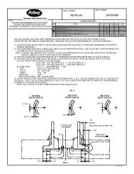
XL-FW10064BM - Holland Group Inc.
XL-FW10064BM - Holland Group Inc.
XL-FW10064BM - Holland Group Inc.

You also want an ePaper? Increase the reach of your titles
YUMPU automatically turns print PDFs into web optimized ePapers that Google loves.
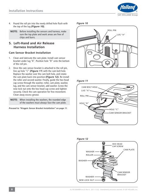
Installation Instructions4. Pound the roll pin into the newly drilled hole flush withthe top of the lug (Figure 10).NOTE: Before installing the sensors and harness, makesure the top plate and work areas are free ofchips and burrs.5. Left-Hand and Air ReleaseHarness InstallationCam Sensor Bracket Installation1. Clean and lubricate the cam plate. Install cam sensorbracket under lug “A”. Position hole “B” onto the bottomof the roll pin.2. Once the cam sensor bracket is attached to the roll pin,line up hole “C” (Figure 11) with the cam bolt hole.Replace the washer over the cam bolt hole, and rotatethe cam plate back into position (Figure 12). Re-installthe roller and second washer. Finally, guide the hex headcap screw through the washer, roller, cam plate, washer,lug, and the cam sensor bracket, add washer. Screw thenew lock nut onto the hex head cap screw and tightensecurely. Check the cam operation for free movement.Clean away excess grease.NOTE: When installing the washers, the rounded edgeof the washers must always face the cam plate.Proceed to “Kingpin Sensor Bracket Installation” on page 11.Figure 10Figure 11Figure 128<strong>XL</strong>-<strong>FW10064BM</strong>-en-US Rev A · 2011-12-02 · Amendments and errors reserved. © SAF-HOLLAND, <strong>Inc</strong>.