XL-FW10064BM - Holland Group Inc.
XL-FW10064BM - Holland Group Inc.
XL-FW10064BM - Holland Group Inc.

You also want an ePaper? Increase the reach of your titles
YUMPU automatically turns print PDFs into web optimized ePapers that Google loves.
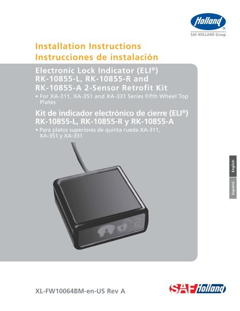
Installation InstructionsInstrucciones de instalaciónElectronic Lock Indicator (ELI ® )RK-10855-L, RK-10855-R andRK-10855-A 2-Sensor Retrofit KitKit de indicador electrónico de cierre (ELI ® )RK-10855-L, RK-10855-R y RK-10855-AEspañolEnglish<strong>XL</strong>-<strong>FW10064BM</strong>-en-US Rev A
ContentsContentsPageIntroduction ......................................................................... 2Notes, Cautions, and Warnings ............................................. 2Section 1 – Model Identification........................................... 3Section 2 – General Safety Instructions ................................ 3Exploded View and Parts List ................................................ 4Section 3 – Top Plate Removal.............................................. 5Section 4 – Left-Hand and Air Release Installation ................ 7ContentsPageSection 5 – Left-Hand and Air Release Harness Installation ..... 8Section 6 – Right-Hand Release Installation ......................... 9Section 7 – Right-Hand Release Harness Installation .......... 10Section 8 – Kingpin Sensor Bracket Installation .................. 11Section 9 – Sensor Position Check ...................................... 12Section 10 – Top Plate Installation ..................................... 13Section 11 – Wire Routing Procedure ................................. 14IntroductionThis manual provides retrofit procedures for installing theElectronic Lock Indicator System (ELI) for the <strong>Holland</strong> FW35series fifth wheels. See page 3 for exact model identification.NOTE: For <strong>Holland</strong> replacement components contactSAF-HOLLAND Customer Service: 888-396-6501.Notes, Cautions, and WarningsYou must read and understand all of the procedures presentedin this manual before starting work on any Electronic LockIndicator System (ELI) for the <strong>Holland</strong> FW35 series fifth wheels.IMPORTANT: Keep this manual in a safe location forfuture reference.Proper tools must be used to perform the maintenance andrepair procedures described in this manual.NOTE: In the United States, work shop safety requirementsare defined by federal and/or state OccupationalSafety and Health Acts. Equivalent laws may existin other countries. This manual is written basedon the assumption that OSHA or other applicableemployee safety regulations are followed by thelocation where work is performed.Throughout this manual, you will notice the terms “NOTE,”“IMPORTANT,” “CAUTION,” and “WARNING” followedby useful product information. So that you may betterunderstand the manual, those terms are defined as follows:NOTE: <strong>Inc</strong>ludes additional information to enable accurateand easy performance of procedures.IMPORTANT: <strong>Inc</strong>ludes additional information thatif not followed could lead to hinderedproduct performance.Used without the safety alert symbol,indicates a potentially hazardoussituation which, if not avoided, mayresult in property damage.Indicates a potentially hazardoussituation which, if not avoided, mayresult in minor or moderate injury.Indicates a potentially hazardoussituation which, if not avoided, couldresult in death or serious injury.2<strong>XL</strong>-<strong>FW10064BM</strong>-en-US Rev A · 2011-12-02 · Amendments and errors reserved. © SAF-HOLLAND, <strong>Inc</strong>.
Model Identification1. Model IdentificationThis manual contains retrofit procedures for installing anElectronic Lock Indicator (ELI) on the 3500 Fifth Wheel Top Plate(XA-351 Series), and for the 3500 LowLube Fifth Wheel Top Plate(XA-331 Series) manufactured after January 1, 1997, as well as3500 NoLube fifth wheel top plate (XA-311 Series) (Figure 1).The ELI is NOT available for FW3500 fifth wheel top platesmanufactured before December 31, 1996 (Figure 2).2. General Safety InstructionsRead and observe all Warning and Caution hazard alert messagesin this publication. They provide information that can help preventserious personal injury, damage to components, or both.The Electronic Lock Indicator System (ELI) installation mustbe performed by a trained technician using proper tools andsafe procedures.Figure 1IMPORTANT: The Electronic Lock Indicator (ELI) is a tractortrailerfifth wheel coupling aid and is intendedas an additional safety check to assure thedriver of a safe and complete coupling. Itdoes not eliminate the requirement for avisual inspection of the fifth wheel. Alwaysget out of the tractor cab and visually inspectthe fifth wheel coupling before proceeding.IMPORTANT: Prior to operation of the fifth wheel you mustbe thoroughly satisfied that the fifth wheelhas been properly installed on the vehicle.Failure to properly install, the fifth wheel mayresult in tractor trailer separation which, if notavoided, could result in death or serious injury.Figure 2EnglishRefer to SAF-<strong>Holland</strong> Installation Manual <strong>XL</strong>-FW10008IM-en-US(available on the Internet at www.safholland.us) for properinstallation procedures.We recommend only the use of HOLLAND Original Parts.A list of SAF-HOLLAND technical support locations to supplySAF-HOLLAND Original Parts can be found at www.safholland.usor contact our customer service group at 888-396-6501.Updates to this manual will be published as necessary on theInternet at www.safholland.us.<strong>XL</strong>-<strong>FW10064BM</strong>-en-US Rev A · 2011-12-02 · Amendments and errors reserved. © SAF-HOLLAND, <strong>Inc</strong>.3
Exploded View and Parts List82REQUIRED TOOLS AND SUPPLIESw DESCRIPTION PART NO. QTY.1 Extension Cable, 2-sensor XB-10754 12 Assembly Module, 2-sensor XB-10758-12 13 Harness Subassembly, 2-sensor, LH XA-10776-L 1Harness Subassembly, 2-sensor, RH XA-10776-R 1Air Release XA-10766-A 14 Cable Tie, Nylon XB-01961 75 XB-10074 26 Roll Pin, 5 mm dia. x 22 mm Large XB-21-S-5M-22M 27 Spring Clip XB-09976 58 Fastener, Reclosable XB-09782 29 Drill Fixture, ELI Kingpin XA-10067 110 Drill Fixture, ELI Lock XA-10055 111 Loom, Corrugated (part of 1, XB-10754) 112* XB-08559 213* XA-1029 114 † XB-10068 115 † XB-T-69-A 116 Grommet XB-10086 117 Retaining Ring XB-07398 218 † Drill bit, #1 Split Point XB-10083 119 † Drill bit, #7 Split Point XB-10084 120 † XB-PW-1732-1-116 1COMPLETED LEFT-HAND VIEW SHOWN(UNDERSIDE)* Not included in this kit. Items are listed only for reference.† <strong>Inc</strong>luded in this kit, but not shown in this drawing.4 <strong>XL</strong>-<strong>FW10064BM</strong>-en-US Rev A · 2011-12-02 · Amendments and errors reserved. © SAF-HOLLAND, <strong>Inc</strong>.
Installation Instructions3. Top Plate RemovalNOTE: Some fifth wheel assemblies have replaceablepocket inserts installed between fifth wheeltop plate and mounting base. Take care whenremoving the fifth wheel top plate not to losepocket inserts.Figure 3Failure to prevent pocket inserts fromfalling out of the top plate could causea potentially hazardous situation which,if not avoided, may result in minor ormoderate injury.1. Remove bracket pin retention bolts and nuts from bothsides of fifth wheel top plate (Figure 3).2. Using a pry bar, pull bracket retention pins out of fifthwheel top plate (Figure 3).3. Using a lifting device capable of lifting 500 lbs. (227 kg),remove top plate from mounting base. Place fifth wheelupside down on a flat, clean working area.NOTE: Follow instructions published by lifting devicemanufacturer for proper operation of lifting device.English<strong>XL</strong>-<strong>FW10064BM</strong>-en-US Rev A · 2011-12-02 · Amendments and errors reserved. © SAF-HOLLAND, <strong>Inc</strong>.5
Installation Instructions4. Remove retaining rings from lock pins and discard(Figure 4).5. Place drill fixture over lock pins (Figure 5) with “UP”mark facing up. Clamp the fixture to the fifth wheel. Remove and discard the fixture. DO NOT reuse thedrill fixture (Figure 6).Figure 4NOTE: Before proceeding, make sure the top plate andwork areas are free of chips and burrs.7. Install the new retaining rings (Figure 4).8. Determine whether your top plate has a right-hand, left-hand,or air release and follow the appropriate instructions. Forleft-hand release and air release, see pages 7 and 8. Forright-hand release, see pages 9 and 10.Figure 5Figure 66<strong>XL</strong>-<strong>FW10064BM</strong>-en-US Rev A · 2011-12-02 · Amendments and errors reserved. © SAF-HOLLAND, <strong>Inc</strong>.
Installation Instructions4. Left-Hand and AirRelease InstallationNOTE: For right-hand release instructions, see page 9.Figure 71. Remove the cam bolt and rotate the cam away fromlug “A” (Figure 7).2. Place drill fixture on top of the lugs with the “L” facingup. Place the cam bolt into the fixture. Insert the locatorpin into the hole in lug “B” (Figure 8).3. Clamp drill fixture to the fifth wheel. Drill through lug “A”with a #7 (0.201) drill bit (Figure 9). Remove and discardthe drill fixture. DO NOT reuse the fixture.Figure 8EnglishFigure 9<strong>XL</strong>-<strong>FW10064BM</strong>-en-US Rev A · 2011-12-02 · Amendments and errors reserved. © SAF-HOLLAND, <strong>Inc</strong>.7
Installation Instructions4. Pound the roll pin into the newly drilled hole flush withthe top of the lug (Figure 10).NOTE: Before installing the sensors and harness, makesure the top plate and work areas are free ofchips and burrs.5. Left-Hand and Air ReleaseHarness InstallationCam Sensor Bracket Installation1. Clean and lubricate the cam plate. Install cam sensorbracket under lug “A”. Position hole “B” onto the bottomof the roll pin.2. Once the cam sensor bracket is attached to the roll pin,line up hole “C” (Figure 11) with the cam bolt hole.Replace the washer over the cam bolt hole, and rotatethe cam plate back into position (Figure 12). Re-installthe roller and second washer. Finally, guide the hex headcap screw through the washer, roller, cam plate, washer,lug, and the cam sensor bracket, add washer. Screw thenew lock nut onto the hex head cap screw and tightensecurely. Check the cam operation for free movement.Clean away excess grease.NOTE: When installing the washers, the rounded edgeof the washers must always face the cam plate.Proceed to “Kingpin Sensor Bracket Installation” on page 11.Figure 10Figure 11Figure 128<strong>XL</strong>-<strong>FW10064BM</strong>-en-US Rev A · 2011-12-02 · Amendments and errors reserved. © SAF-HOLLAND, <strong>Inc</strong>.
Installation Instructions6. Right-Hand Release Installation1. Remove the cam bolt and rotate the cam away fromlug “B“ (Figure 13).2. Place drill fixture on top of the lugs with the “R” facingup. Put cam bolt into the fixture. Insert locator pin intothe hole in lug “A” (Figure 14).3. Clamp the drill fixture to the fifth wheel. Drill throughlug “B” with a #7 (0.201) drill bit (Figure 15). Removethe fixture after drilling. DO NOT reuse the drill fixture.Figure 13Figure 14EnglishFigure 15<strong>XL</strong>-<strong>FW10064BM</strong>-en-US Rev A · 2011-12-02 · Amendments and errors reserved. © SAF-HOLLAND, <strong>Inc</strong>.9
Installation Instructions4. Pound the roll pin into the newly drilled hole flush withthe top of the lug (Figure 16).Figure 16NOTE: Before installing the sensors and harness, makesure the top plate and work areas are free ofchips and burrs.7. Right-Hand ReleaseHarness InstallationCam sensor bracket installation1. Clean and lubricate the cam plate. Install cam sensorbracket under lug “B” (Figure 17). Position hole “B”onto the bottom of the roll pin.2. Once the cam sensor bracket is attached to the rollpin, line up hole “C” with the cam bolt hole. Place thewasher over the cam bolt hole, and rotate the cam plateback into position (Figure 17). Re-install the roller andsecond washer. Finally, guide the hex head cap screwthrough the washer, roller, cam plate, washer, lug, thecam sensor bracket, and washer (Figure 18). Screw thenew lock nut onto the hex head cap screw and tightensecurely. Check the cam operation for free movement.Clean away excess grease.NOTE: When installing the washers, the rounded edgeof the washers must always face the cam plate.Figure 17Figure 1810<strong>XL</strong>-<strong>FW10064BM</strong>-en-US Rev A · 2011-12-02 · Amendments and errors reserved. © SAF-HOLLAND, <strong>Inc</strong>.
Installation Instructions8. Kingpin Sensor Bracket Installation1. Mount the kingpin sensor bracket to the fifth wheel(Figure 19) with the thread-cutting screws. Torquescrews to 12 ft.-lbs. DO NOT overtighten the screws.DO NOT use air or impact tools.NOTE: The kingpin sensor bracket mounts in the sameposition for both left-hand, right-hand and airrelease fifth wheels.2. Assemble the cable ties and spring clips together beforepressing the clips onto the casting (Figure 20).3. Route the harness on the fifth wheel as shown (Figure 21).Use clips and cable ties to fasten the harness to the fifthwheel ribs in the locations shown (Figure 21).NOTE: A left-hand release fifth wheel is shown here. Fora right-hand release, the cam sensor bracket andwiring are mirrored on the opposite side of thetop plate.4. Re-install the fifth wheel top plate onto the tractor.Figure 19KINGPINSENSORBRACKETFigure 20THREAD-CUTTINGSCREWSCABLE TIEEnglishFigure 21<strong>XL</strong>-<strong>FW10064BM</strong>-en-US Rev A · 2011-12-02 · Amendments and errors reserved. © SAF-HOLLAND, <strong>Inc</strong>.11
Installation Instructions9. Sensor Position Check1. Lock the fifth wheel top plate using a <strong>Holland</strong> lock testerTF-TLN-5001 and flip the top plate upside down.2. Check to make sure the cam plate (Figure 22) andthe kingpin (Figure 23)respective sensor. Pull the cam plate, by hand, away fromthe sensor as far as possible when checking the distance.The cam must not be able to touch the sensor. The camsensor bracket may be bent slightly to adjust its distancefrom the cam. To avoid damaging the sensor, only pry onthe metal when bending the bracket. DO NOT pry on thesensor. After adjusting, push cam towards sensor, makingsure they do not touch.3. Remove the lock tester and check that the kingpin sensoris not to close to the locks when they are open. Therethe bottom of the locks (Figure 24). If the distanceis close the kingpin bracket can be bent slightly. Afteradjusting away from the locks, recheck the distance tothe kingpin by use of the lock tester.Figure 223/8"THERE SHOULD BEA GAP OF 3/8" ORLESS BETWEEN THECAM PLATE ANDTHE CAM SENSORFigure 23CAM SENSORCAM PLATEFigure 2412<strong>XL</strong>-<strong>FW10064BM</strong>-en-US Rev A · 2011-12-02 · Amendments and errors reserved. © SAF-HOLLAND, <strong>Inc</strong>.
Installation Instructions10. Top Plate InstallationFigure 251. Visually inspect both pocket inserts for excessive wear, chips,cracks or gouges. If any of these conditions are found, thepocket insert(s) must be replaced (Figure 25). For pocketinsert replacements, contact SAF-HOLLAND CustomerService and request RK-PKT-2.2. If pocket inserts are dislodged from fifth wheel casting,clean pocket area of casting and apply a strip of doubleface tape in bottom of pockets. Install pocket inserts bypressing them down into the pocket areas (Figure 26).3. Using a lifting device capable of lifting 500 lbs. (227 kg),install fifth wheel top plate onto its mounting base.NOTE: Follow instructions published by lifting devicemanufacturer for proper operation of lifting device.4. Install bracket pins through fifth wheel casting andmounting base and secure by installing the bracket pinsretention bolts and nuts (Figure 27). Torque retentionFigure 26EnglishFigure 27<strong>XL</strong>-<strong>FW10064BM</strong>-en-US Rev A · 2011-12-02 · Amendments and errors reserved. © SAF-HOLLAND, <strong>Inc</strong>.13
Installation Instructions11. Wire Routing Procedure1. Mount the display box in the cab so that it is easilyvisible and accessible to the driver. Clean the dash anddisplay box mounting surfaces with isopropyl alcohol,and allow to air dry. Use the provided, re-closableadhesive fastener to mount the display box on the dash.2. Route the cable on the Electronic Lock Indicator (ELI)display box to approximately where the 25' extensioncable will enter the cab.3. Install corrugated loom around extension cable(Figure 28).4. Cut one (1) slit into the grommet (Figure 29).5. Wrap the grommet around the 25' extension cable in theapproximate location where it will enter the cab. sure that there are no obstructions near the drilling area.7. Run the end of the 25' extension cable with the powerlines through the utility hole and into the cab.8. Install the 1-amp fuse, which is included with theextension cable (Figure 30). power wire and the tractor’s positive (+) power wire.It is recommended that a switched terminal in themain fuse box be used so that power is suppliedwhen the ignition is turned on.b. Insert the wires into each end of the fuse holder.c. Crimp the terminal through the fuse holder body.Failure to connect a voltage source thatmatches the specification on the boxwill result in a damaged and inoperabledisplay box.9. Connect the 2-wire power cable from the extension cable toa 12- or 24-volt power supply. (The back of each displaybox is marked with 12- or 24-VDC.) Be sure to connect theRED wire with the fuse — as outlined in Step 8 — to thepositive (+) terminal, and the BLACK wire to the (-) terminal.Figure 28Figure 29Figure 3014<strong>XL</strong>-<strong>FW10064BM</strong>-en-US Rev A · 2011-12-02 · Amendments and errors reserved. © SAF-HOLLAND, <strong>Inc</strong>.
Installation Instructions10. Connect the 25' extension cable to the ELI display boxcable inside the cab.11. Press the grommet into position in the utility hole. Applysealant to the grommet and extension cable to preventmoisture intrusion into the cab.12. Route the 25' extension cable from the cab to the fifthwheel (Figure 31).13. Route the wire clear of pinch points.NOTE: For sliding fifth wheels, be sure to leave enoughslack for travel and route the wire clear of pinchpoints. It can be helpful to route the wire throughan existing coiled air line.Figure 3112V14. Secure the 25' extension cable so that it is free ofinterference from the fifth wheel articulation, brakelines, light cord, drive line etc.15. Connect the 25' extension cable to the wire harness onthe fifth wheel (Figure 32).16. Test ELI for proper operation:a. Make sure the fifth wheel locks are open.b. Turn on the ignition/power. The ELI display shouldrun through a short system check, shown by the briefillumination of the three display icons (Figure 33).After the system check is complete, the yellow“Ready to Couple” icon should be illuminated.NOTE: If the display does not illuminate or an iconother than the yellow “Ready to Couple” icon isilluminated, proceed directly to the SAF-HOLLANDELI Troubleshooting Guide <strong>XL</strong>-FW10063TS-en-US.c. Lock the fifth wheel top plate using a <strong>Holland</strong> lock tester(TF-TLN-5001). The green “Closed Lock” icon shouldbe illuminated to indicate a proper coupling. If thegreen icon does not appear: observing how quickly the handle and cam plate moveinto position. If the mechanism is sluggish; lubricatethe cam, yoke tips and the handle according to theprocedures found in your fifth wheel owner’s manual. operation of the locking mechanism. correctly and the green “Closed Lock” icon still doesnot illuminate, proceed directly to the SAF-HOLLANDELI Troubleshooting Guide <strong>XL</strong>-FW10063TS-en-US.For operating and maintenance instructions, see SAF-HOLLANDELI Owner's Manual <strong>XL</strong>-FW10062UM-en-US.Figure 32Figure 33English<strong>XL</strong>-<strong>FW10064BM</strong>-en-US Rev A · 2011-12-02 · Amendments and errors reserved. © SAF-HOLLAND, <strong>Inc</strong>.15
THIS PAGE INTENTIONALLY BLANK
Instrucciones de instalaciónKit de indicador electrónicode cierre (ELI ® ) RK-10855-L,RK-10855-R y RK-10855-A<strong>XL</strong>-<strong>FW10064BM</strong>-es-US Rev A
ContenidoContenidoPáginaIntroducción ..............................................................................18Notas, precauciones y advertencias ..........................................18Sección 1 – Identificación de modelo ........................................19Sección 2 – Instrucciones generales de seguridad .................... 19Vista esquemática y lista de piezas ...........................................20Sección 3 – Desmontaje de la placa superior ............................ 21Sección 4 – Instalación de izquierda y liberación neumática .... 23ContenidoPáginaSección 5 – Instalación de arnés de liberación neumáticao izquierda ............................................................24Sección 6 – Instalación de liberación a la derecha .................... 25Sección 7 – Instalación de arnés de liberación a la derecha ..... 26Sección 8 – Instalación de soporte de sensor del perno rey ...... 27Sección 9 – Comprobación de posición del sensor ................... 28Sección 10 – Instalación de la placa superior............................ 29Sección 11 – Procedimiento para el tendido de cables .......... 300IntroducciónEste manual muestra procedimientos de actualización parainstalar el Sistema indicador electrónico de cierre (ELI) paraquinta rueda serie FW35 de <strong>Holland</strong>. Vea en la página 3 laidentificación exacta de los modelos.NOTA: Para obtener repuestos <strong>Holland</strong> comuníquese conServicio al cliente de SAF-HOLLAND: 888-396-6501.Notas, precauciones y advertenciasDebe leer y comprender todos los procedimientos presentados eneste manual antes de comenzar a trabajar en cualquier Sistemaindicador electrónico de cierre (ELI) para las quintas ruedas serieFW35 de <strong>Holland</strong>.IMPORTANTE: Guarde este manual en un lugar seguro paraconsultarlo en el futuro.Se deben usar las herramientas adecuadas para practicar losprocedimientos de mantenimiento y reparación descritos eneste manual.NOTA: En Estados Unidos los requisitos de seguridad en eltaller están definidos por leyes de salud y seguridadocupacional federales o estatales (OSHA). Es posibleque existan leyes equivalentes en otros países. Estemanual se escribió basándose en la suposición deque se siguen las normas de seguridad de empleadosde la OSHA u otras normas aplicables en el lugar enque se ejecute el trabajo.A lo largo de este manual, usted encontrará los términos “NOTA”,“IMPORTANTE”, “PRECAUCIÓN” y “ADVERTENCIA” seguidos deinformación importante sobre el producto. Para que comprendamejor el manual, esos términos se definen en la forma siguiente:NOTA: <strong>Inc</strong>luye información adicional para permitir la realizaciónmás sencilla y exacta de los procedimientos.IMPORTANTE: <strong>Inc</strong>luye información adicional que, de noatenderse podría ocasionar una disminuciónen el rendimiento del producto.PRECAUCIÓNPRECAUCIÓNADVERTENCIASin el símbolo de alerta de seguridad indicauna situación con riesgo potencial que, si nose evita, puede provocar daños materiales.Indica una situación con riesgo potencialque, si no se evita, puede provocar lesionesmenores o moderadas.Indica una situación con riesgo potencialque, si no se evita, puede provocar lamuerte o lesiones graves.18 <strong>XL</strong>-<strong>FW10064BM</strong>-es-US Rev A · 2011-08-02 · Amendments and errors reserved. © SAF-HOLLAND, <strong>Inc</strong>.
Identificación del modelo1. Identificación del modeloEste manual contiene procedimientos para instalar un Indicadorelectrónico de cierre (ELI) en el plato superior de la quinta rueda3500 (Serie XA-351), y para el plato superior de quinta ruedaLowLube 3500 (Serie XA-331), fabricadas después del 1 de enerode 1997, así como el plato superior de quinta rueda NoLube3500 (Serie XA-311) (Figura 1).El ELI NO está disponible para platos superiores de quinta ruedaFW3500 fabricadas antes del 31 de diciembre de 1996 (Figura 2).2. Instrucciones generales de seguridadLea y observe todos los mensajes de alerta de riesgo de Advertenciay precaución de esta publicación. Proporcionan información quepuede ayudar a prevenir lesiones personales graves, daño a loscomponentes, o ambos.La instalación del Sistema indicador electrónico de cierre (ELI)la debe ejecutar un técnico capacitado adecuadamente usandoherramientas adecuadas y siguiendo procedimientos seguros.IMPORTANTE: El Indicador electrónico de cierre (ELI) esun auxiliar de acople de quinta rueda detractocamión-remolque y su objetivo es seruna comprobación de seguridad adicionalpara que el conductor se asegure de unacople seguro y completo. No elimina elrequisito de una inspección visual de laquinta rueda. Salga siempre de la cabinadel tractocamión e inspeccione visualmenteel acople antes de proceder.Figura 1Figura 2IMPORTANTE: Antes de operar la quinta rueda debeconvencerse plenamente de que ésta seinstaló correctamente en el vehículo.EspañolADVERTENCIAEl no instalar la quinta rueda correctamentepuede causar una separación entre eltractocamión y el remolque que, de noevitarse, podría producir la muerte olesiones graves.Consulte el Manual de instalación SAF-<strong>Holland</strong> <strong>XL</strong>-FW10008IM-sx-US(disponible en Internet en www.safholland.us) para conocerlos procedimientos de instalación correctos.Recomendamos usar solamente repuestos originales HOLLAND.Se puede encontrar una lista de lugares de asistencia técnica deSAF-HOLLAND que suministran repuestos originales SAF-HOLLANDen www.safholland.us o puede comunicarse con nuestrogrupo de servicio al cliente en 888-396-6501.Las actualizaciones a este manual se publicarán según seanecesario en Internet en www.safholland.us.<strong>XL</strong>-<strong>FW10064BM</strong>-es-US Rev A · 2011-08-02 · Amendments and errors reserved. © SAF-HOLLAND, <strong>Inc</strong>.19
Vista esquemática y lista de piezas82HERRAMIENTAS Y SUMINISTROS NECESARIOSNO. DESCRIPCIÓN NO. DE PARTE CANT.1 Cable de extensión, 2 sensores XB-10754 12 Módulo de ensamble, 2 sensores XB-10758-12 13 Subensamble de arnés, 2 sensores, LH XA-10776-L 1Subensamble de arnés, 2 sensores, RH XA-10776-R 1Liberación neumática XA-10766-A 14 Amarra para cable, nylon XB-01961 75 XB-10074 26Perno de rodillo, 5 mm diám. x 22 mmde long.XB-21-S-5M-22M 27 Clip de resorte XB-09976 58 Sujetador, recerrable XB-09782 29 Accesorio para taladro, perno rey ELI XA-10067 110 Accesorio para taladro, cierre ELI XA-10055 111 Conducto, corrugado (parte de 1, XB-10754) 112* XB-08559 213* XA-1029 1Tornillo de cabeza hueca hexagonal14 † XB-10068 115 † XB-T-69-A 116 Pasacables XB-10086 117 Anillo de retención XB-07398 218 † Broca, #1 punta partida XB-10083 119 † Broca #7 Punta partida XB-10084 120 † XB-PW-1732-1-116 1* No incluído en este juego. Los elementos se mencionan sólo como referencia.† Se incluye en la lista pero no se muestra en el dibujo.SE MUESTRA VISTA IZQUIERDA TERMINADA(LADO INFERIOR)20 <strong>XL</strong>-<strong>FW10064BM</strong>-es-US Rev A · 2011-08-02 · Amendments and errors reserved. © SAF-HOLLAND, <strong>Inc</strong>.
Instrucciones de instalación3. Desmontaje del plato superiorNOTA: Algunos ensambles de quinta rueda tienen insertosinstalados entre el plato superior de la quintarueda y la base de montaje. Al desmontar el platosuperior de la quinta rueda tenga cuidado de noperder los insertos.Figura 3El no evitar la caída de los insertos dePRECAUCIÓNla placa superior podría causar unasituación potencialmente peligrosa que,si no se evita, puede causar lesionesmenores o moderadas.1. Retire los pernos de retención y las tuercas del perno delsoporte de ambos lados del plato superior de la quintarueda (Figura 3).2. Usando una palanca, saque los pasadores de retenciónde la placa superior de la quinta rueda (Figura 3).3. Usando un dispositivo de elevación capaz de levantar500 libras (227 kg), retire el plato superior de la base demontaje. Ponga la quinta rueda boca abajo en un área detrabajo plana y limpia.NOTA: Siga las instrucciones publicadas por el fabricante deldispositivo de elevación para operarlo correctamente.Español<strong>XL</strong>-<strong>FW10064BM</strong>-es-US Rev A · 2011-08-02 · Amendments and errors reserved. © SAF-HOLLAND, <strong>Inc</strong>.21
Instrucciones de instalación4. Retire los anillos de retención de los pasadores de cierrey deséchelos (Figura 4).5. Ponga la guia para taladro sobre los pasadores de cierre(Figura 5) con la marca “UP” hacia arriba. Sujete laguia a la quinta rueda. broca #1 (0,228). Retire y deseche la guia. NO vuelva ausar el accesorio para taladro (Figura 6).Figura 4NOTA: Antes de continuar, asegúrese de que el platosuperior y las áreas de trabajo estén libres detrozos metálicos y rebabas.7. Instale los nuevos anillos de retención (Figura 4).8. Determine si su plato superior tiene liberación derecha,izquierda, o neumática y siga las instrucciones corres pondientes.Para liberación izquierda o neumática, vea las páginas 7y 8. Para liberación derecha, vea las páginas 9 y 10.Figura 5Figura 622 <strong>XL</strong>-<strong>FW10064BM</strong>-es-US Rev A · 2011-08-02 · Amendments and errors reserved. © SAF-HOLLAND, <strong>Inc</strong>.
Instrucciones de instalación4. Instalación de liberación izquierday neumáticaNOTA: Para ver las instrucciones para la liberaciónderecha, vea la página 9.1. Retire el perno de leva y gire la leva para alejarla de laoreja “A” (Figura 7).2. Ponga la guia para taladro sobre las orejas con la “L”hacia arriba. Ponga el perno de leva en la guia. Inserteel pasador de ubicación en el orificio en la oreja “B”(Figura 8).3. Sujete la guia para taladro a la quinta rueda. Perforea través de la oreja “A” con una broca #7 (0,201)(Figura 9). Retire y deseche la guia para taladro.NO vuelva a usar el accesorio.Figura 7Figura 8EspañolFigura 9<strong>XL</strong>-<strong>FW10064BM</strong>-es-US Rev A · 2011-08-02 · Amendments and errors reserved. © SAF-HOLLAND, <strong>Inc</strong>.23
Instrucciones de instalación4. Golpee el perno de rodillo en el orificio recién taladradohasta que quede al ras con la parte superior de la oreja(Figura 10).NOTA: Antes de instalar los sensores y el arnés, asegúresede que el plato superior y las áreas de trabajoestén libres de trozos metálicos y rebabas.5. Instalación de arnés de liberaciónneumática o izquierdaInstalación del soporte de sensor de levaFigura 101. Limpie y lubrique la placa de leva. Instale el soporte desensor de leva bajo la oreja “A”. Coloque el orificio “B”sobre la parte inferior del perno de rodillo.2. Una vez que el soporte de sensor de leva está unido alperno de rodillo, alinee el orificio “C” (Figura 11) conel orificio del perno de leva. Reemplace la arandela sobreel orificio del perno de leva y gire la placa de leva devuelta a su posición (Figura 12). Vuelva a instalar elrodillo y la segunda arandela. Finalmente, guíe el tornillohexagonal a través de la arandela, rodillo, placa de leva,arandela, oreja y el soporte de sensor de leva, agreguela arandela. Atornille la nueva tuerca de seguridad en eltornillo hexagonal y apriete firmemente. Compruebe quela leva se mueva libremente. Limpie el exceso de grasa.NOTA: Al instalar las arandelas, el borde redondeadode las arandelas debe siempre ver hacia la placade leva.Continúe a “Instalación de soporte de sensor del perno rey”en la página 11.Figura 11Figura 1224 <strong>XL</strong>-<strong>FW10064BM</strong>-es-US Rev A · 2011-08-02 · Amendments and errors reserved. © SAF-HOLLAND, <strong>Inc</strong>.
Instrucciones de instalación6. Instalación de liberacióna la derecha1. Retire el perno de leva y gire la leva para alejarla de laoreja “B“ (Figure 13).2. Ponga la guia para taladro sobre las orejas con la “R”hacia arriba. Ponga el perno de leva en la guia. Inserteel pasador de ubicación en el orificio en la oreja “A”(Figura 14).3. Sujete la guia para taladro a la quinta rueda. Perforea través de la oreja “B” con una broca #7 (0,201)(Figura 15). Retire la guia después de taladrar. NOvuelva a utilizar el accesorio.Figura 13Figura 14EspañolFigura 15<strong>XL</strong>-<strong>FW10064BM</strong>-es-US Rev A · 2011-08-02 · Amendments and errors reserved. © SAF-HOLLAND, <strong>Inc</strong>.25
Instrucciones de instalación4. Golpee el perno de rodillo en el orificio recién taladradohasta que quede al ras con la parte superior de la oreja(Figure 16).NOTA: Antes de instalar los sensores y el arnés, asegúresede que la placa superior y las áreas de trabajoestén libres de trozos metálicos y rebabas.7. Instalación de arnés de liberacióna la derechaInstalación del soporte de sensor de leva1. Limpie y lubrique la placa de leva. Instale el soporte desensor de leva bajo la oreja “B” (Figure 17). Coloque elorificio “B” sobre la parte inferior del perno de rodillo.2. Una vez que el soporte de sensor de leva está unido alperno de rodillo, alinee el orificio “C” (Figura 11) conel orificio del perno de leva. Reemplace la arandela sobreel orificio del perno de leva y gire la placa de leva devuelta a su posición (Figura 17). Vuelva a instalar elrodillo y la segunda arandela. Finalmente, guíe el tornillohexagonal a través de la arandela, rodillo, placa de leva,arandela, oreja y el soporte de sensor de leva, agreguela arandela. Atornille la nueva tuerca de seguridad en eltornillo hexagonal y apriete firmemente. Compruebe quela leva se mueva libremente. Limpie el exceso de grasa.NOTA: Al instalar las arandelas, el borde redondeadode las arandelas debe siempre ver hacia la placade leva.Figura 16Figura 17Figura 1826 <strong>XL</strong>-<strong>FW10064BM</strong>-es-US Rev A · 2011-08-02 · Amendments and errors reserved. © SAF-HOLLAND, <strong>Inc</strong>.
Instrucciones de instalación8. Instalación de soporte de sensor delperno rey1. Monte el soporte de sensor del perno rey en la quintarueda (Figura 19) con los tornillos autorroscantes.Apriete los tornillos a 12 pies-lbs. NO apriete los tornillosde más. NO use herramientas neumáticas o de impacto.NOTA: El soporte de sensor del perno rey se monta en lamisma posición para quinta rueda de liberaciónizquierda, derecha y neumática.2. Una las amarras para cables y los clips de resorte antesde presionar los clips en la pieza fundida (Figura 20).3. Dirija el arnés en la quinta rueda en la forma mostrada(Figura 21). Use los pasadores y las amarras paracables para sujetar el arnés a los rebordes de la quintarueda en las ubicaciones mostradas (Figura 21).NOTA: Aquí se muestra una quinta rueda de liberaciónizquierda. Para una quinta rueda de liberaciónderecha, el soporte de sensor de leva y el cableadose colocan en posiciones simétricas en el ladoopuesto de la placa superior.4. Vuelva a instalar la placa superior de la quinta rueda enel tractocamión.Figura 19SOPORTE DESENSOR DELPERNO REYFigura 20TORNILLOS AUTOR-ROSCANTESAMARRA PARA CABLEEspañolFigura 21<strong>XL</strong>-<strong>FW10064BM</strong>-es-US Rev A · 2011-08-02 · Amendments and errors reserved. © SAF-HOLLAND, <strong>Inc</strong>.27
Instrucciones de instalación9. Comprobación de posicióndel sensor1. Cierre el mecanismo de la quinta rueda usando un probadorde seguros <strong>Holland</strong> TF-TLN-5001 y voltee el plato superiorhacia arriba.2. Compruebe que la placa de la leva (Figura 22) y el pernorey (Figura 23)sensor. Aleje manualmente la placa de leva del sensorlo más posible cuando compruebe la distancia. La levano debe poder tocar el sensor. El sensor de leva sepuede doblar ligeramente para ajustar su distancia dela leva. Para evitar dañar el sensor, sólo haga palancaen el metal al doblar el soporte. NO haga palanca en elsensor. Después de ajustar, empuje la leva hacia el sensor,asegurándose de que no se toquen.3. Retire el probador de seguros y compruebe que el sensordel perno rey no esté cerca de los seguros cuando estény la parte inferior de los seguros (Figura 24). Si estámuy cerca el soporte del perno rey se puede doblar unpoco. Después del ajuste para alejar de los seguros, vuelvaa comprobar la distancia al perno rey mediante el uso delprobador de seguros.Figura 223/8"DEBE EXISTIR UNASEPARACIÓN DE3/8" O MENOS EN-TRE LA PLACA DELEVA Y EL SENSORDE LEVAFigura 23PLACA DE LEVASENSOR DE LEVAFigura 2428 <strong>XL</strong>-<strong>FW10064BM</strong>-es-US Rev A · 2011-08-02 · Amendments and errors reserved. © SAF-HOLLAND, <strong>Inc</strong>.
Instrucciones de instalación10. Instalación de plato superiorFigura 251. Inspeccione visualmente ambos insertos buscando desgasteexcesivo, despostillado, grietas o marcas. Si se encuentracualquiera de estas condiciones, los insertos se debenreemplazar (Figura 25). Para obtener repuestos de insertos,comuníquese con el Servicio al cliente de SAF-HOLLANDy solicite la pieza RK-PKT-2.2. Si los insertos se desprenden de la pieza fundida de laquinta rueda, limpie el área y aplique una tira de cinta dedoble cara en la parte inferior de los asientos. Para instalarlos insertos, presiónelos en los asientos (Figura 26).3. Usando un dispositivo de elevación capaz de levantar500 libras (227 kg), instale el plato superior de la quintarueda en su base de montaje.NOTA: Siga las instrucciones publicadas por el fabricante deldispositivo de elevación para operarlo correctamente.4. Instale los pernos del soporte a través de la pieza fundidade la quinta rueda y la base de montaje y asegure instalandolos pernos de retención y las tuercas de los pernos delsoporte (Figura 27). Apriete los pernos de retención sinFigura 26EspañolFigura 27<strong>XL</strong>-<strong>FW10064BM</strong>-es-US Rev A · 2011-08-02 · Amendments and errors reserved. © SAF-HOLLAND, <strong>Inc</strong>.29
Instrucciones de instalación11. Procedimiento para el tendidode cables1. Monte la caja de la pantalla en la cabina de modo quepueda ser vista y esté al alcance del conductor. Limpie lassuperficies de contacto del tablero y la caja de la pantallacon alcohol isopropílico y deje secar. Use el sujetadorautoadhesivo resellable suministrado con el productopara montar la caja de la pantalla sobre el tablero.2. Tienda el cable de la caja de la pantalla del Indicadorelectrónico de cierre (ELI) hasta aproximadamente el lugaren que el cable de extensión de 25' entrará a la cabina.3. Instale el ducto corrugado y el cable de extensión(Figura 28).4. Corte una (1) ranura en el pasacables (Figura 29).5. Envuelva el cable de extensión de 25' con el pasacablesen la ubicación aproximada en que entrará a la cabina. asegurándose de que no haya obstrucciones cerca delárea de la perforación.7. Tienda el extremo del cable de extensión de 25' con laslíneas de energía a través del orificio y hacia la cabina.El no conectar una fuente de alimentaciónque cumpla la especificación de la caja dañaráy dejará inservible la caja de la pantalla.Figura 28Figura 298. Instale el fusible de 1 amperio, que se incluye con elcable de extensión (Figura 30). del cable de extensión y el hilo de energía positiva (+)del tractocamión. Es recomendable que utilice un terminalconmutado en la caja de fusibles principal para que seproporcione energía cuando la ignición se encienda.b. Inserte los hilos en cada extremo del portafusibles.c. Engarce la terminal a través del cuerpo del portafusibles.9. Conecte el cable de energía de 2 hilos desde el cable deextensión a una fuente de alimentación de 12 o 24-voltios.(La parte posterior de cada caja de pantalla está marcadacomo 12 o 24 VDC). Asegúrese de volver a conectar elhilo ROJO con el fusible, como se indica en el Paso 8, alterminal positivo (+), y el hilo NEGRO al terminal (-).Figura 3030 <strong>XL</strong>-<strong>FW10064BM</strong>-es-US Rev A · 2011-08-02 · Amendments and errors reserved. © SAF-HOLLAND, <strong>Inc</strong>.
Instrucciones de instalación10. Conecte el cable de extensión de 25' al cable de la cajade la pantalla ELI dentro de la cabina.11. Haga presión sobre el pasacables para colocarlo en elorificio. Aplique sellador al pasacables y el cable deextensión para impedir que la humedad entre a la cabina.12. Tienda el cable de extensión de 25' desde la cabina a laquinta rueda (Figura 31).13. Tienda el cable sin pasar por puntos de aplastamiento.NOTA: Para quintas ruedas deslizantes, asegúrese de dejarsuficiente espacio libre para el recorrido y tender elcable lejos de puntos de presión. Puede ser útil tenderel cable a través de una línea de aire enrollada existente.14. Asegure el cable de extensión de 25' de modo que estélibre de interferencia de la articulación de la quintarueda, líneas de frenado, cable de luz, transmisión, etc.15. Conecte el cable de extensión de 25' al arnés de cable enla quinta rueda (Figura 32).16. Pruebe que el ELI esté funcionando correctamente:a. Asegúrese de que los seguros de la quinta ruedaestén abiertos.b. Encienda la ignición. La pantalla del ELI ejecutará unabreve comprobación de sistema; esto se muestra aliluminarse brevemente los tres íconos de la pantalla(Figura 33). Después de terminada la comprobacióndel sistema, se deberá iluminar el ícono amarillo“Listo para acoplar”.Figura 31Figura 3212VNOTA: Si la pantalla no se ilumina o se enciende un íconoque no sea el ícono amarillo “Listo para acoplar”,diríjase directamente a la Sección 2.A. de la Guíade resolución de problemas de ELI SAF-HOLLAND<strong>XL</strong>-FW10063TS-sx-US.c. Cierre el mecanismo de la quinta rueda usando unprobador de seguros <strong>Holland</strong> (TF-TLN-5001). El íconoverde de “Seguro cerrado” se deberá iluminar para indicarun acople adecuado. Si el ícono verde no aparece: a fijarlos mientras observa con qué rapidez regresan asu lugar la manija y la placa de leva. Si el mecanismo eslento; lubrique la leva, los extremos de la horquilla y lamanija siguiendo los procedimientos que se encuentranen su manual del propietario de la quinta rueda. operación del mecanismo de seguridad. funciona correctamente y el ícono verde “Segurocerrado” aún no se ilumina, continúe directamentea la sección 2.B de la Guía de resolución de problemas deELI SAF-HOLLAND <strong>XL</strong>-FW10063TS-sx-US.Para obtener instrucciones de operación y mantenimiento, vea elManual del propietario de ELI SAF-HOLLAND <strong>XL</strong>-FW10062UM-sx-US.Figura 33Español<strong>XL</strong>-<strong>FW10064BM</strong>-es-US Rev A · 2011-08-02 · Amendments and errors reserved. © SAF-HOLLAND, <strong>Inc</strong>.31
From fifth wheel rebuild kits to suspension bushing repair kits,SAF-HOLLAND Original Parts are the same quality components usedin the original component assembly.SAF-HOLLAND Original Parts are tested and designed to providemaximum performance and durability. Will-fits, look-alikes or, worseyet, counterfeit parts will only limit the performance potential andcould possibly void SAF-HOLLAND’s warranty. Always be sure to specSAF-HOLLAND Original Parts when servicing yourSAF-HOLLAND product.SAF-HOLLAND USA · 888.396.6501 · Fax 800.356.3929www.safholland.usSAF-HOLLAND CANADA · 519.537.3494 · Fax 800.565.7753WESTERN CANADA · 604.574.7491 · Fax 604.574.0244www.safholland.caSAF-HOLLAND MEXICO · +(52) 55.5362.8743 · Fax +(52) 55.5362.8743www.safholland.com.mxinfo@safholland.com<strong>XL</strong>-<strong>FW10064BM</strong>-en-US Rev A · 2011-12-02 · Amendments and errors reserved. © SAF-HOLLAND, <strong>Inc</strong>.SAF-HOLLAND USA, INC.1950 Industrial Blvd., Muskegon, MI 49443www.safholland.com