warning - Scag Power Equipment
warning - Scag Power Equipment
warning - Scag Power Equipment

You also want an ePaper? Increase the reach of your titles
YUMPU automatically turns print PDFs into web optimized ePapers that Google loves.
MODEL STT61V-25KBD-SSTHIS MANUAL CONTAINS THE OPERATINGINSTRUCTIONS AND SAFETY INFORMA-TION FOR YOUR SCAG MOWER. READINGTHIS MANUAL CAN PROVIDE YOU WITHASSISTANCE IN MAINTENANCE AND AD-JUSTMENT PROCEDURES TO KEEP YOURMOWER PERFORMING TO MAXIMUM EFFI-CIENCY. THE SPECIFIC MODELS THAT THISBOOK COVERS ARE CONTAINED ON THEINSIDE COVER. BEFORE OPERATING YOURMACHINE, PLEASE READ ALL THE INFOR-MATION ENCLOSED.© 2006SCAG POWER EQUIPMENTDIVISION OF METALCRAFT OF MAYVILLE, INC.OPERATOR’S MANUALPART NO. 03198PRINTED 11/06PRINTED IN USA
WARNING:FAILURE TO FOLLOW SAFE OPERATING PRACTICESMAY RESULT IN SERIOUS INJURY.* Read this manual completely as well as other manuals that camewith your mower.* DO NOT operate on steep slopes. To check a slope, attempt to backup it (with the cutter deck down). If the machine can back up the slopewithout the wheels slipping, reduce speed and use extreme caution.Under no circumstances should the machine be operated on slopesgreater than 15 degrees. ALWAYS FOLLOW OSHA APPROVEDOPERATION.* DO NOT mow on wet grass. Wet grass reduces traction and steeringcontrol.* Keep all shields in place, especially the grass discharge chute.* Before performing any maintenance or service, stop the machine andremove the spark plug wire and ignition key.* If a mechanism becomes clogged, stop the engine before cleaning.* Keep hands, feet and clothing away from power-driven parts.* Keep others off the tractor (only one person at a time)REMEMBER - YOUR MOWER IS ONLY AS SAFE AS THE OPERATOR!Hazard control and accident prevention are dependent upon the awareness,concern, prudence, and proper training of the personnel involved in theoperation, transport, maintenance, and storage of the equipment.This manual covers the operating instructionsand illustrated parts list for:STT61V-25KBD-SSwith a serial number of D1000001 to D1099999Always use the entire serial number listed on the serial numbertag when referring to this product.
TABLE OF CONTENTSSUBJECTPAGESection 1 - General Information1.1 Introduction .............................................................................................................................11.2 Directional Reference .............................................................................................................11.3 Servicing the Engine and Drive Train Components ................................................................11.3 Symbols ............................................................................................................................... 2-3Section 2 - Safety Information2.1 Introduction .............................................................................................................................42.2 Signal Words ...........................................................................................................................42.3 Considerations Before Operation ...........................................................................................42.4 Operation Considerations ........................................................................................................52.5 Roll Over Protection System ..................................................................................................72.6 Maintenance Considerations ...................................................................................................92.7 Safety and Instructional Decals ............................................................................................10Section 3 - Specifications ....................................................................................................11-12Section 4 - Operating Instructions4.1 Controls and Instrument Identification ..................................................................................134.2 Safety Interlock System ........................................................................................................144.3 Initial Run-In Procedures ......................................................................................................154.4 Starting the Engine ................................................................................................................154.5 Ground Travel and Steering ..................................................................................................154.6 Engaging the Deck Drive .....................................................................................................164.7 Hillside Operation .................................................................................................................174.8 Parking the Mower ...............................................................................................................174.9 After Operation ....................................................................................................................174.10 Removing Clogged Material .................................................................................................184.11 Moving Mower with Engine Stopped ...................................................................................184.12 Recommendations for Mowing .............................................................................................184.13 Adjusting Cutting Height .......................................................................................................194.14 Towing ..................................................................................................................................194.15 Adjusting the Steering Levers ...............................................................................................204.16 Adjusting the Height Adjust Pedal ........................................................................................20Section 5 - Troubleshooting Cutting Conditions ............................................................. 21-23I
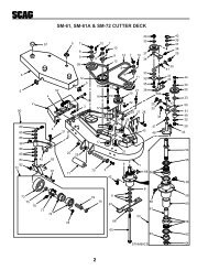
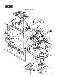
SUBJECTTABLE OF CONTENTS (CONT'D)PAGESection 6 - Adjustments6.1 Parking Brake Adjustment .................................................................................................... 246.2 Travel Adjustments ...............................................................................................................246.3 Throttle Control Adjustments ................................................................................................266.4 Belt Adjustment ....................................................................................................................266.5 Belt Alignment ......................................................................................................................266.6 Cutter Deck Adjustments .....................................................................................................27Section 7 - Maintenance7.1 Maintenance Chart ...............................................................................................................307.2 Lubrication Fitting Points ......................................................................................................317.3 Hydraulic System ..................................................................................................................337.4 Engine Oil .............................................................................................................................347.5 Engine Fuel System ..............................................................................................................357.6 Engine Air Cleaner................................................................................................................367.7 Battery ..................................................................................................................................367.8 Drive Belts ............................................................................................................................377.9 Cutter Blades ........................................................................................................................377.10 Tires ......................................................................................................................................387.11 Cutter Deck Gearbox ...........................................................................................................387.12 Cooling System .....................................................................................................................397.13 Body, Deck and Upholstery ..................................................................................................40Section 8 - Replacement PartsSTT61V Cutter Deck ............................................................................................................... 42-43Cutter Deck Controls................................................................................................................ 44-45Sheet Metal Components.......................................................................................................... 46-47STT Roll Over Protection System with Suspension Seat ......................................................... 48-49Deck Drive Components .......................................................................................................... 50-51Engine and Attaching Parts (Kubota Diesel)............................................................................ 52-53Brake and Steering Components .............................................................................................. 54-55Fuel and Hydraulic System ....................................................................................................... 56-57Hydraulic Pump with Cooling Fan (BDP-16A) ........................................................................ 58-59Electrical System ...................................................................................................................... 60-61Replacement Decals ................................................................................................................. 62-63Electrical Schematic (Kubota Diesel) ............................................................................................64Warranty Statement .............................................................................................. following section 8II
RSection 11.1 INTRODUCTIONYour mower was built to the highest standards in theindustry. However, the prolonged life and maximumefficiency of your mower depends on you following theoperating, maintenance and adjustment instructions in thismanual.If additional information or service is needed, contactyour <strong>Scag</strong> <strong>Power</strong> <strong>Equipment</strong> Dealer.We encourage you to contact your dealer for repairs. All<strong>Scag</strong> dealers are informed of the latest methods toservice this equipment and provide prompt and efficientservice in the field or at their service shop. They carry afull line of <strong>Scag</strong> service parts.THE REPLACEMENT OF ANY PART ON THISPRODUCT BY OTHER THAN THEMANUFACTURER'S AUTHORIZEDREPLACEMENT PART MAY ADVERSELYAFFECT THE PERFORMANCE, DURABILITY ORSAFETY OF THIS PRODUCT.USE OF OTHER THAN ORIGINAL SCAGREPLACEMENT PARTS WILL VOID THEWARRANTY.GENERAL INFORMATION<strong>Scag</strong> approved attachments and accessories:GC-STT-61V (p/n 9060)GC-STT-CS61V (p/n 9064)Mulch Plate (p/n 9288)Hurricane Mulch (p/n 9285)STT Hitch (p/n 9242)STT Bumper (p/n 9256)STT Lights (p/n 9279)Tiger Striper (p/n 9269)Blade Buddy (p/n 9212)WARNING:For pictorial clarity, some illustrations and figuresin this manual may show shields, guards or platesopen or removed. Under no circumstances shouldyour mower be operated without these devices inplace.All information is based upon product informationavailable at the time of approval for printing. <strong>Scag</strong><strong>Power</strong> <strong>Equipment</strong> reserves the right to makechanges at any time without notice and withoutincurring any obligation.1.2 DIRECTION REFERENCEWhen ordering parts, always give the model and serialnumber of your mower. The serial number plate islocated where shown in Figure 1-1.SERIAL NUMBERPLATE LOCATIONMANUFACTURED UNDER ONE OR MOREOF THE FOLLOWING PATENTS:PATENTS PENDING4,487,006 4,991,382 5,832,7084,885,903 4,998,948 5,865,0184,920,733 5,118,6174,967,543 5,826,416MODELSERIALDivision of Metalcraft of Mayville, Inc.Mayvi le, Wisconsin 53050Patents Issued and PendingThe “Right” and “Left”, “Front” and “Rear” of themachine are referenced from the operator’s right and leftwhen seated in the normal operating position and facingthe forward travel direction.1.3 SERVICING THE ENGINE AND DRIVETRAIN COMPONENTS390S0137AFigure 1-1 Mower Serial Number Plate LocationUSE ONLY SCAG APPROVED ATTACHMENTSAND ACCESSORIES.Attachments and accessories manufactured by companiesother than <strong>Scag</strong> <strong>Power</strong> <strong>Equipment</strong> are not approved for useon this machine.1The detail servicing and repair of the engine, hydraulicpumps and gearboxes are not covered in this manual;only routine maintenance and general service instructionsare provided. For service of these components during thelimited warranty period, it is important to contact your<strong>Scag</strong> dealer or find a local authorized servicing agent ofthe component manufacturer. Any unauthorized workdone on these components during the warranty periodmay void your warranty.
SymbolsSYMBOLDESCRIPTIONSYMBOLDESCRIPTIONChokeTransmissionParking BrakeSpinning Blade48071SOn/StartSpring Tension on IdlerOff/StopOilWARNINGFalling HazardFALLING HAZARDUSE ONLY SCAG APPROVEDRIDING ATTACHMENTSSEE OPERATOR'S MANUAL 481109Thown Object HazardSeat must be installed under the seathold down bracket during installation.Failure to secure the seat under the holddown bracket could result in seriousinjury or death in a roll over.CE Mark2
SYMBOL DESCRIPTION SYMBOL DESCRIPTIONFastSlowContinuously Variable - LinearCutting Element - Basic SymbolPinch PointCutting Element - Engage481039SHourmeter/Elapsed Operating HoursCutting Element - DisengageThown Object HazardKeep Bystanders AwayRead Operator's Manual3
Section 22.1 INTRODUCTIONSAFETY INFORMATIONYour mower is only as safe as the operator.Carelessness or operator error may result in seriousbodily injury or death. Hazard control and accidentprevention are dependent upon the awareness, concern,prudence, and proper training of the personnel involved inthe operation, transport, maintenance and storage of theequipment. Make sure every operator is properly trainedand thoroughly familiar with all of the controls beforeoperating the mower. The owner/user can prevent and isresponsible for accidents or injuries occuring tothemselves, other people or property.READ THIS OPERATOR’S MANUAL BEFOREATTEMPTING TO START YOUR MOWER.A replacement manual is available from your authorized<strong>Scag</strong> Service Dealer or by contacting <strong>Scag</strong> <strong>Power</strong><strong>Equipment</strong>, Service Department at P.O. Box 152,Mayville, WI 53050 or contact us via the Internet atwww.scag.com. The manual for this machine can bedownloaded by using the model and serial number or usethe contact form to make your request. Please indicatethe complete model and serial number of your <strong>Scag</strong>product when requesting replacement manuals.2.2 SIGNAL WORDSThis symbol means “Attention! Become Alert! YourSafety is Involved!" The symbol is used with thefollowing signal words to attract your attention to safetymessages found on the decals on the machine andthroughout this manual. The message that follows thesymbol contains important information about safety. Toavoid injury and possible death, carefully read themessage! Be sure to fully understand the causes ofpossible injury or death.Signal Word:It is a distinctive word found on the safety decals on themachine and throughout this manual that alerts theviewer to the existence and relative degree of thehazard.4The signal word “DANGER” denotes that an extremelyhazardous situation exists on or near the machine thatcould result in high probability of death or irrepairableinjury if proper precautions are not taken.WARNING:The signal word “WARNING” denotes that a hazardexists on or near the machine that can result in injury ordeath if proper precautions are not taken.CAUTION:The signal word “CAUTION” is a reminder of safetypractices on or near the machine that could result inpersonal injury if proper precautions are not taken.Your safety and the safety of others depends significantlyupon your knowledge and understanding of all correctoperating practices and procedures of this machine.2.3 BEFORE OPERATIONCONSIDERATIONS1. NEVER allow children to operate this riding mower.Do not allow adults to operate this machine withoutproper instructions.2. DO NOT mow when children and/or others arepresent. Keep children out of the mowing area andin the watchful care of a responsible adult other thanthe operator. Be alert and turn machine off if a childenters the area.3. DO NOT allow children to ride or play on themachine, it is not a toy.4. Clear the area to be mowed of objects that could bepicked up and thrown by the cutter blades.5. DO NOT carry passengers.
Section 26. DO NOT operate the machine under the influence ofalcohol or drugs.7. If the operator(s) or mechanic(s) cannot readEnglish or Spanish, it is the owner's responsibility toexplain this material to them.8. DO NOT wear loose fitting clothing. Looseclothing, jewelry or long hair could get tangled inmoving parts. Do not operate the machine wearingshorts; always wear adequate protective clothingincluding long pants. Wearing safety glasses, safetyshoes and a helmet is advisable and is required bysome local ordinances and insurance regulations.WARNING:Always wear hearing protection. Operating thismachine over prolonged periods of time cancause loss of hearing.9. Keep the machine and attachments in good operatingcondition. Keep all shields and safety devices inplace. If a shield, safety device or decal is defectiveor damaged, repair or replace it before operating themachine.WARNING:This machine is equipped with an interlock systemintended to protect the operator and others frominjury. This is accomplished by preventing theengine from starting unless the deck drive isdisengaged, the parking brake is on, the steeringcontrol levers are in the neutral position and theoperator is in the seat. The system shuts off theengine if the operator leaves the seat with the deckdrive engaged and/or the steering control levers arenot in the neutral postion and the parking brake isnot engaged. Never operate equipment with theinterlock system disconnected or malfunctioning.10. Be sure the interlock switches are functioningcorrectly.11. Fuel is flammable; handle it with care. Fill the fueltank outdoors. Never fill it indoors. Use a funnel orspout to prevent spillage. Clean up any spillagebefore starting the engine.512. DO NOT add fuel to a running or hot engine. Allowthe engine to cool for several minutes before addingfuel. Never fuel indoors or enclosed trailers.13. Keep flammable objects (cigarettes, matches, etc.),open flames and sparks away from the fuel tank andfuel container. Use only approved containers.14. <strong>Equipment</strong> must comply with the latest requirementsper SAE J137 and/or ANSI/ASAE S279 whendriven on public roads.-NOTE-If the mower is driven on public roads, it mustcomply with state and local ordinances as well asSAE J137 and/or ANSI / ASAE S279requirements. Contact your local authorities forregulations and equipment requirements.15. DO NOT operate without the side discharge chuteinstalled and in the down position or with an optionalgrass catcher or mulch plate completely installed.16. Check the blade mounting bolts at frequent intervalsfor proper tightness.17. Make sure all hydraulic fluid connections are tight andall hydraulic hoses and lines are in good conditionbefore starting the machine.2.4 OPERATION CONSIDERATIONS1. Know the function of all controls and how to stopquickly.WARNING:DO NOT operate on steep slopes. To check a slope,attempt to back up it (with the cutter deck down).If the machine can back up the slope without thewheels slipping, reduce speed and use extremecaution. Under no circumstances should themachine be operated on slopes greater than 15degrees. ALWAYS FOLLOW OSHA APPROVEDOPERATION.
Section 22.4 OPERATION CONSIDERATIONS(CONT'D)2. Reduce speed and exercise extreme caution on slopesand in sharp turns to prevent tipping or loss ofcontrol. Be especially cautious when changingdirections on slopes.3. To prevent tipping or loss of control, start and stopsmoothly, avoid unnecessary turns and travel at reducedspeed.4. When using any attachment, never direct the dischargeof material toward bystanders or allow anyone nearthe machine while in operation.5. Before attempting to start the engine, with the operatorin the seat, disengage power to the cutter deck, placethe steering control levers in the neutral position andengage the parking brake.6. If the mower discharge ever plugs, shut off the engine,remove the ignition key, and wait for all movement tostop before removing the obstruction.WARNING:DO NOT use your hand to dislodge the cloggeddischarge chute. Use a stick or other device toremove clogged material after the engine hasstopped running and the blades have stoppedturning.7. Be alert for holes, rocks, roots and other hidden hazardsin the terrain. Keep away from any dropoff. Bewareof overhead obstructions (low limbs, etc.), undergroundobstacles (sprinklers, pipes, tree roots, etc.). Cautiouslyenter a new area. Be alert for hidden hazards.8. Disengage power to cutter deck before backing up.Do not mow in reverse unless absolutely necessaryand then only after observation of the entire area behindthe mower. If you must mow in reverse, maintain aconstant lookout to the rear of the machine and mowslowly.10. Disengage power to cutter deck before crossing roads,walks or gravel drives.11. Mow only in daylight or good artificial light.12. NEVER raise the deck with the blades engaged.13. Take all possible precautions when leaving the machineunattended, such as disengaging the mower, loweringthe attachments, setting the parking brake, stopping theengine, and removing the key.14. Disengage power to the attachments when transportingor when not in use.15. The machine and attachments should be stopped andinspected for damage after striking a foreign object,and damage should be repaired before restarting andoperating the machine.CAUTION:DO NOT touch the engine or the muffler whilethe engine is running or immediately afterstopping. These areas may be hot enough tocause a burn.DO NOT run the engine inside a building or aconfined area without proper ventilation. Exhaustfumes are hazardous and contain carbon monoxidewhich can cause brain injury and death.16. Keep hands and feet away from cutter blades andmoving parts. Contact can injure.17. Use care when loading or unloading the machine ontoa trailer or truck.18. Use care when approaching blind corners, shrubs, trees,or other objects that may obscure vision.19. NEVER leave the machine running unattended.9. DO NOT turn sharply. Use care when backing up.6
Section 22.5 ROLL-OVER PROTECTION SYSTEMLower the roll bar only when absolutely necessary.WARNING:Keep the roll bar in the raised and lockedposition and the seat belt securely fastenedduring operation. Failure to do so couldcause serious injury or loss of life.1. To lower the roll bar, loosen the tension knob on boththe left hand and right hand bar. See Figure 2-1.2. Remove the hairpin cotter pins and remove the (2) twolock pins. See Figure 2-2.3. Lower the roll bar to the down position.This mower has been designed for good traction andstability under normal mowing conditions. However,caution must be used when traveling on slopes, especiallywhen the grass is wet. Do not mow on wet grass. Wetgrass reduces traction and steering control.Any or all parts of the Roll-Over Protection SystemMUST NOT be removed. Failure to adhere to thisguideline could result in injury or death.4. To raise the roll bar, lift the bar to the upright position.5. Install the (2) two lock pins through the hole, securewith the (2) two hairpin cotter pins and tighten thetension knobs. See Figure 2-2. Remove the seat beltfrom the retainer brackets.UPRIGHT ANDLOCKED POSITIONWARNING:There is no roll-over protection when the roll bar isin the down position.Lower the roll bar only when absolutelynecessary.TENSIONKNOBSRaise the roll bar as soon as clearance permits.DO NOT wear the seat belt when the roll bar isin the down position.Figure 2-1 Foldable Roll-Over Protection SystemALWAYS wear seat belt when roll bar is in theup position.Operate the machine smoothly, no sudden turns,starts or stops.LOCK PINHAIR PINTENSIONKNOBCheck the area carefully before mowing for properoverhead clearance (i.e. branches, doorways, etc.).Figure 2-2 ROPS HingeDO NOT contact any overhead object with the rollbar.7
Section 2The potential exposure of the seat belt to severeenviromental conditions make it crucial to inspect the seatbelt system regularly.It is recommended that the seat belt be inspected on adaily basis for signs of damage. Any seat belt system thatshows cuts, fraying, extreme or unusual wear, significantdiscoloration due to UV exposure, dirt or stiffness,abrasion to the seat belt webbing, or damage to thebuckle, latch plate, hardware or any other obviousproblem should be replaced immediately.WARNING:Failure to properly inspect and maintain theseat belt can cause serious injury or loss oflife.1. Check the full length of the seat belt webbing forcuts, wear, fraying, dirt and stiffness. See Figure 2-3.2. Check the seat belt webbing in areas exposed to ultraviolet rays from the sun or extreme dust or dirt. If theoriginal color of the webbing in these areas isextremely faded and/or is packed with dirt, thephysical strength of this webbing may havedeteriorated. If this condition exists, replace the seatbelt system.3. Check the buckle and latch for proper operation anddetermine if the latch plate is excessively worn,deformed, or if the buckle is damaged or cracked.See Figure 2-3.WARNING:Reduce speed when turning, operating on slopes,slick or wet surfaces. Allow extra distance to stop.Stay off of slopes too steep for safe operation. Tocheck a slope, attempt to back up it (with the cutterdeck down). If the machine can not back up theslope without the wheels slipping, do not operatethe machine on this slope. Under no circumstancesshould the machine be operated on slopes greaterthan 15 degrees.ALWAYS travel up or down the slope wheneverpossible. Never across the slope.DO NOT mow near drop-offs, ditches orembankments. The machine could suddenly rollover if a wheel goes over the edge or if the edgecaves in.Operate the machine smoothly, no sudden turns,starts or stops on a slope.NEVER tow on slopes. The weight of the towedequipment may cause loss of traction and loss ofcontrol.DO NOT permit untrained personnel to operatethe machine.INSPECT BUCKLE& LATCHINSPECT WEBBINGFigure 2-3 Seat Belt Inspection8
Section 22.6 MAINTENANCE CONSIDERATIONS &STORAGE1. Never make adjustments to the machine with theengine running unless specifically instructed to do so.If the engine is running, keep hands, feet, andclothing away from moving parts.2. Disengage drives, lower implement, set parkingbrake, stop engine and remove key or disconnectspark plug wire to prevent accidental starting of theengine when servicing or adjusting the machine.Wait for all movement to stop before adjusting,cleaning or repairing.3. Disconnect battery or remove spark plug wire beforemaking any repairs. Disconnect the negativeterminal first and the positive last. Reconnect thepositive first and the negative last.4. Keep all nuts, bolts and screws tight, to ensure themachine is in safe working condition. Check blademounting bolts frequently to be sure they are tight.5. Do not change the engine governor settings oroverspeed the engine. See the engine operator'smanual for information on engine settings.6. To reduce fire hazard, keep the cutting units, drives,muffler and engine free of grass, leaves, excessivegrease, oil and dirt.11. Use jack stands to support components whenrequired.12. Carefully release pressure from components withstored energy.WARNING:Hydraulic fluid is under high pressure. Keepbody and hands away from pinholes or nozzlesthat eject hydraulic fluid under high pressure.If you need service on your hydraulic system,please see your authorized <strong>Scag</strong> dealer. Ifhydraulic fluid is injected into the skin, it mustbe surgically removed within a few hours by adoctor or gangrene may result.13. Let the engine cool before storing.14. DO NOT store the machine near an open flame.15. Shut off fuel while storing or transporting.16. DO NOT store fuel near flames or drain indoors.17. Charge batteries in an open, well ventilated area,away from spark and flames. Unplug charger beforeconnecting or disconnecting from battery. Wearprotective clothing and use insulated tools.7. Park the machine on level ground and engage theparking brake.8. NEVER allow untrained personnel to service themachine.9. Use care when checking blades. Use a BladeBuddy, wrap the blade(s) or wear gloves and USECAUTION when servicing blades. Only replaceblades. NEVER straighten or weld blades.10. Keep all parts in good working condition. Replace allworn or damaged decals.9
Section 3SPECIFICATIONS3.1 ENGINEGeneral Type ............................................................................. Heavy Duty Industrial/Commercial DieselBrand ......................................................................................... Kubota 25HP Diesel (Spec. #D902-E2B-KAE-2 (1G447-00000)Model ........................................................................................ Kubota D902Horsepower ............................................................................... 25 HP at 3600 RPM (Model STT61V-25KBD-SS)Type ........................................................................................... 4 Cycle Diesel, 3 Cylinder, Horizontal Shaft, Water CooledDisplacement............................................................................ 25HP Kubota 898cc.Cylinders ................................................................................... 3 with Cast-Iron SleevesGovernor ................................................................................... Mechanical Type with Variable Speed Control Set At 3670 RPMIdle Speed .................................................................................. 1200 RPMFuel Injection ............................................................................ Injection Pump, Bosch MD Mini TypeFuel ............................................................................................ Diesel Fuel with a minimum cetane rating of 40Oil Pump Group ........................................................................ Positive Displacement Gerotor Oil Pump with Oil FilterStarter ........................................................................................ Electric Starting with Solenoid Shift StarterBelts: .......................................................................................... Kevlar cord. Self-adjusting, Self-tighteningDeck Drive Belt...................................................................... <strong>Scag</strong> Part Number - 481460Pump Drive Belt (29HP & Higher) ....................................... <strong>Scag</strong> Part Number - 4830863.2 ELECTRICALBattery ....................................................................................... 12 VoltCharging System ........................................................................ AlternatorCharging Output ........................................................................ 12 Volt, 40 AmpSystem Polarity .......................................................................... Negative GroundStarter......................................................................................... 12 Volt Electric Ring Gear Type, Key and Solenoid Operated InterlockSwitches ..................................................................................... Seat, Neutral Control, Mower Engagement (BBC), Parking BrakeInstrument Panel ....................................................................... Volt Meter, Key Switch, Throttle Lever, BBC Switch, Temp. Gauge................................................................................................... Fuses, Safety Start module, Oil Pressure Gauge, Glow Plug IndicatorFuses .......................................................................................... Two (1) 20 Amp, (1) 50 Amp Resettable3.3 TRACTORDrive System ............................................................................. Hydraulic Drive with Two Variable Displacement Pumps and Two................................................................................................... Cast-iron High Torque MotorsHydrostatic Pumps .................................................................... Two Hydro-Gear BDP 16A Pumps with Dump Valves formovement without running the engine and pressure relief valvesDrive Wheel Motors ................................................................. Two Ross Model TG 15 cu. inch Cast-Iron High-Torque MotorsSteering/Travel Control ............................................................. Twin Lever Fingertip Steering Control with Individual Control toEach Wheel with Gas Spring DampersParking Brake ............................................................................. Lever Actuated Linkage to Brakes on Both Drive Wheel AxlesWheels:(2) Front Caster .................................................................... 13 X 6.00 Four Ply(2) Drive ............................................................................... 24X12.0X12 Four-Ply Pneumatic Tubeless, Radius Edge, 61" & 72"Fuel Tank ................................................................................... 10-Gallon Seamless Polyethylene Tank with large opening andFuel Gauge Fill CapTire Pressure:Front Caster .......................................................................... Flat FreeDrive ..................................................................................... 12 PSISeat ............................................................................................ Padded, Suspension SeatTravel Speed:Forward ................................................................................. 0-12 MPHReverse ................................................................................. 0-6 MPH-NOTE-The machine will travel at 12mph for transport purposes.For best cutting performance the forward travel speedshould be adjusted depending upon the cutting conditions.11
Section 33.4 CUTTER DECKType: .......................................................................................... Floating, Adjustable, Anti-scalping, Hybrid Design CombinesOut-front and Belly-mount DesignsConstruction:............................................................................. 10-gauge steel reinforced with 7-gauge (3/16") Support Plate.7-gauge (3/16") deck skirt.True Cutting Width: .................................................................. 61" (155.0 cm)Cutting Height Adjustment: ....................................................... Foot Operated Lever Adjustment from Operator's Seat, 1.00" to6.00" in 1/4"incrementsCutter Blades:............................................................................ .197 Thick, Milled Edge, Wear Resistant MarbainSMT 61V: Three (3) 21" bladesBlade Engagement: ................................................................... Electric Blade Engagement Clutch with Control Panel SwitchConnected to the Cutter Deck Gearbox through a Drive Shaft.Discharge Opening: ................................................................... Extra Wide 11.5" Discharge Opening with Spring LoadedDischarge ChuteDischarge Chute..................................................................................Black, Polypropylene (Plastic), FlexibleCaster Wheels: .......................................................................... 13 X 6.00 Four-PlySpindles: .................................................................................... Heavy-duty 1-1/8" Top Dimension Spindle Shaft, Cast Housing,Taper Roller Bearing, Low Maintenance with Top Access GreaseFitting and Grease Overfill Relief PoppetSpindle Pulleys: .......................................................................... Split Steel with Easily Removed Taper HubsCutter Deck Belts: .................................................................... B-section with Kevlar Cord. Self-adjusting, Self-tighteningSMT61 .................................................................................. <strong>Scag</strong> Part Number - 481558Electric Clutch Type ................................................................. Ogura Electric ClutchDrive Shaft ................................................................................. Clamp Yoke Shaft With Two High Speed U-Joints3.6 HYDRAULIC SYSTEMHydraulic Oil Filter ..................................................................... 10 Micron Spin-on Element TypeHydraulic Reservoir ................................................................... Nylon; 3 Quart Capacity3.7 WEIGHTS AND DIMENSIONS SMT61VLength 87.5"Tracking Width 55"Overall Width73.5" w/chute down, 62" w/chute upOverall Height67.5" w/ROPS up, 56.5" w/ROPS downOperating Weight 1540#3.8 PRODUCTIVITYThe following chart will aid you in determining how many acres your <strong>Scag</strong> mower will cut per day.The chart is an estimate based on 8 hours per day cutting time at 6 MPH with an allowance for overlap and turns.Cutting Width: 61"Acres Per Day: 23.712
OFFOFFOFFC HSection 4OPERATING INSTRUCTIONSCAUTION:Do not attempt to operate this mower unless youhave read this manual. Learn the location andpurpose of all controls and instruments before youoperate this mower.4.1 CONTROLS AND INSTRUMENTIDENTIFICATIONBefore operating the mower, familiarize yourself with allmower and engine controls. Knowing the location,function and operation of these controls is important forsafe and efficient operation of the mower.1. Ignition Switch (Figure 4-1). The ignition switchis used to start the engine and has three positions;OFF, ON, and START.2. Mower Deck Switch (Figure 4-1). Used to engageand disengage the mower drive system. Pulling up onthe switch will engage the deck drive. Pushing downon the switch will disengage the deck drive.3. Glow Plug Indicator (Figure 4-1). Yellow indicatorturns off when the glow plugs have been properlyheated after the ignition switch is turned on.4. Engine Throttle Control (Figure 4-1). Used tocontrol the engine speed. Pushing the lever forwardincreases engine speed. Pulling the lever backdecreases engine speed. Full back position is theIDLE position. Full forward is the cutting position.5. Voltmeter (Figure 4-1). Indicates the condition ofthe charging system. When the engine is running, innormal operating conditions, the needle should be inthe 12 to 14 volt range.DECK LIFTLEFT STEERINGCONTROLRIGHT STEERINGCONTROLWATER TEMPERATUREPARKING BRAKECONTROLCUTTING HEIGHTADJUSTMENTMOWER DECK SWITCHDECK RELEASEOIL PRESSUREGLOW PLUG INDICATORSEAT BELTENGINETHROTTLECONTROLaljalefj airjf;o3rfaf krjf ;wsorgf aljalefj airjf;o3rfaljalefj airjf;o3rfIGNITION SWITCHFUEL GAUGEFUSESVOLTMETERDUMP VALVEHOURMETERSTT-25KBD2007CONTROLSFigure 4-1 Controls and Instruments13
Section 46. Oil Pressure (Figure 4-1). Indicates engine oilpressure. Reference the engine operator's manualfor further information.7. Hourmeter (Figure 4-1). Indicates the number ofhours the engine has been operated. It operateswhenever the engine is running. Has presetmaintenance reminders for engine and hydraulicsystem oil changes. Will start flashing scheduledmaintenance 2 hours before preset time and continueflashing until 2 hours after. Automatically resets.8. Fuse Holders (Figure 4-1). There are one 20-ampfuse and one 50-amp resettable fuse that protect themower’s electrical system. To replace fuse, pull fuseout of the socket and install a new fuse.9. Left Steering Control (Figure 4-1). Used to controlthe mower's left wheel when traveling forward orreverse.10. Right Steering Control (Figure 4-1). Used tocontrol the mower's right wheel when travelingforward or reverse.11. Parking Brake Control (Figure 4-1). Used toengage and disengage the parking brakes. Pull thelever back to engage the parking brakes. Push thelever forward to disengage the parking brakes.12. Fuel Tank Gauge (Figure 4-1). Indicates theamount of fuel in the fuel tank.13. Dump Valve Control Levers (Figure 4-2). Locatedon the hydraulic pumps, used to “free-wheel” themower. Rotating the levers clockwise until they stopallows the unit to move under hydraulic power. Thelevers must be in this position and torqued to 10ft/lbsduring operation of the mower. Rotating the leverscounter-clockwise allows the mower to be moved byhand (free-wheeling).14. Deck Lift Foot Lever (Figure 4-1). Used to raiseand lower the cutter deck.DUMP VALVECONTROL2007 STTDVCFigure 4-2 Dump Valve Control16. Deck Release Lever (Figure 4-1). Used to lock thecutter deck in the transport position. Push the footpedal forward and lift up on the release lever torelease the cutter deck for normal mowing.17. Temperature Gauge (Figure 4-1). Indicates theoperating temperature of the engine.18. Seat Belt (Figure 4-1). Used to secure the operator.Seat belt must be worn at all times when the ROPS isin the upright and locked position.4.2 SAFETY INTERLOCK SYSTEMThe mower is equipped with a safety interlock systemthat prevents the engine from starting unless the deckdrive is disengaged, the parking brake is engaged, thesteering control levers are in the neutral position and theoperator is in the seat. The interlock system shuts offthe engine if the operator leaves the seat with thesteering control levers not in the neutral position and/orthe cutter blades engaged and the parking brake notengaged.WARNING:Never operate the mower with the interlocksystem disconnected or malfunctioning. Donot disengage or bypass any switch; injury toyourself and others or property damage couldresult.15. Cutting Height Adjustment (Figure 4-1). Used toset the cutter deck at the desired cutting height.14
Section 44.3 INITIAL RUN-IN PROCEDURES (FirstDay of Use or Approximately 10 Hours)1. Check all belts for proper alignment and wear at 2, 4and 8 hours.2. Change the engine oil and oil filter after the first 20hours of operation. (See Section 7.4.)3. Check hydraulic oil level in reservoir. (See Section7.3.)4. Check for loose hardware. Tighten as needed.5. Check interlock system for proper operation. (SeeSection 4.2.)6. Check tire pressure. Adjust pressure if necessary.(See Section 7.10)4.4 STARTING THE ENGINEDO NOT USE STARTING FLUIDS. Use of startingfluids in the air intake system may be potentiallyexplosive or cause a “runaway” engine conditionthat could result in engine damage and/or personalinjury.1. Be sure the fuel shutoff valve, located behind theoperator's seat, is completely open. (See Section 7.5Page 35)2. Secure the ROPS in the upright and locked position.3. Sit in the operator’s seat, fasten seat belt and placethe steering control levers in the neutral position.4. Engage the parking brake.CAUTION:5. Place the PTO switch in the disengaged position.6. Move the engine throttle control to about half enginespeed.157. Turn the ignition key to the on position until theyellow indicator for the glow plugs goes out. Thenturn the ignition key to the START position andrelease the key as soon as the engine starts. Do nothold the key in the START position for more than 15seconds at a time. Allow at least 60 secondsbetween each cranking attempt to preventoverheating of the starter motor. Prolonged crankingcan damage the starter motor and shorten batterylife.8. Allow engine to warm before operating the mower.4.5 GROUND TRAVEL AND STEERINGIf you are not familiar with the operation of amachine with lever steering and/or hydrostatictransmissions, the steering and ground speedoperations should be learned and practiced inan open area, away from buildings, fences, orobstructions. Practice until you are comfortablewith the handling of the machine beforeattempting to mow. Learn the operation on flatground before operating on slopes.-IMPORTANT--IMPORTANT-Start practicing with a slow engine speed andslow forward travel.Learn to feather the steering controls to obtaina smooth operating action.Practice operating the mower until you arecomfortable with the controls before proceedingto mow.Forward TravelTo travel forward with the mower, disengage the parkingbrake and slowly push the steering control levers forwardan equal distance. The further the steering control leversare pushed forward, the greater the forward speed willbe. To increase the speed, push the steering controllevers further forward and to decrease the speed, pull thesteering control levers back.
Section 4To stop the forward travel, pull the steering control leversback to the neutral position.To steer the mower left while traveling forward, pull theleft steering lever back. The further the lever is pulledback, the quicker the mower will turn left.To steer the mower right while traveling forward, pull theright steering control lever back. The further the lever ispulled back, the quicker the mower will turn right.-NOTE-Smooth operation of the steering levers willproduce smooth mower operation. Whilelearning the operation of the steering controls,keep the travel speed low.-IMPORTANT-Do not travel forward over a curb. The mowerwill hang up on the curb. Raise the deck andtravel backwards over the curb at a 45 degreeangle. (see Section 4.13 on Page 19 for cutterdeck raising instructions)Reverse TravelCAUTION:Disengage power to the mower before backing up.Do not mow in reverse unless absolutely necessaryand then only after observation of the entire areabehind the mower.-NOTE-The mower may not travel straight in reverse.Slight adjustments may need to be made usingthe steering controls.To steer left while traveling in reverse, allow the leftsteering control lever to move forward. The further thecontrol is allowed to move forward, the quicker themower will turn left.To steer right while traveling in reverse, allow the rightsteering control lever to move forward. The further thecontrol is allowed to move forward, the quicker themower will turn right.To stop the reverse travel, allow the steering controllevers to return to the neutral position. If the mower is tobe parked, engage the parking brake.4.6 ENGAGING THE DECK DRIVE (CUTTERBLADES)1. Set the throttle at about 3/4 speed. Do not attempt toengage the deck drive at high speed as this shortensthe electric clutch life — use only moderate enginespeed when engaging the deck drive.2. Engage the deck drive by pulling out on the yellowswitch, located on the instrument panel, (Figure 4-3)to the engage position.CAUTION:Before backing up, observe the rear for persons andobstructions. Clear the area before backing up.Possible injury or property damage could occur.PULL UP TO ENGAGEPUSH DOWN TO DISENGAGESTT99CESTo travel in reverse, pull both handles back. Keep thetravel speed low while traveling in reverse.16Figure 4-3 Cutter Engage Switch-NOTE-A squealing noise may be heard whenengaging or disengaging the deck drive. It iscaused by the electric clutch plates meshing asthe mower comes up to speed.
Section 43. To disengage the deck drive, push the switch in to thedisengage position.4. Always operate the engine at full throttle to properlymaintain cutting speed. If the engine starts to lugdown, reduce the forward speed and allow theengine to operate at maximum RPM.4.7 HILLSIDE OPERATIONWARNING:DO NOT operate on steep slopes. To check a slope,attempt to back up it (with the cutter deck down).If the machine can back up the slope without thewheels slipping, reduce speed and use extremecaution. Under no circumstances should themachine be operated on slopes greater than 15degrees.ALWAYS FOLLOW OSHA APPROVEDOPERATION.1. This mower has been designed for good traction andstability under normal mowing conditions. However,caution must be used when traveling on slopes,especially when the grass is wet. Wet grass reducestraction and steering control. The Roll-OverProtection System is standard equipment for thismachine. See Section 2.5, page 7 of this manual forfurther details.2. To prevent tipping or loss of control, do not start orstop suddenly, avoid unnecessary turns and travel atreduced speed. If tires loose traction, disengageblades and proceed slowly off the slope.4.8 PARKING THE MOWER1. Park the machine on a flat, level surface only. Do notpark the machine on an incline.2. Place the steering control levers in the neutralposition.3. Disengage the cutter blades4. Slow the engine to idle speed.5. Engage the parking brake.6. Turn the ignition key to the OFF position and removethe key.4.9 AFTER OPERATION1. Wash the entire mower after each use. Do not usehigh pressure spray or direct the spray onto electricalcomponents.-IMPORTANT-Do not wash a hot or running engine. Coldwater will damage the engine. Use compressedair to clean the engine if it is hot.2. Keep the entire mower clean to inhibit serious heatdamage to the engine or hydraulic oil circuit.3. Check the drive belts for proper alignment and anysigns of wear. Correct and adjust if necessary.3. Avoid sudden starts when mowing uphill. Suddenstarts may cause the machine to tip backwards.4. Loss of traction may occur when traveling down hill.Weight transfers to the front of the machine and maycause the drive wheels to slip causing loss of brakingor steering.5. Keep tires properly inflated.To avoid injury from burns, allow the mower to coolbefore removing the fuel tank cap and refueling.4. After the mower has cooled down, fill the fuel tankwith fresh, clean fuel with a minimum cetane ratingof 40 at the end of every day of operation.5. Check the tire pressure. Adjust pressure if necessary.17
Section 44.10 REMOVING CLOGGED MATERIAL4.12 RECOMMENDATIONS FOR MOWINGROTATING BLADESNEVER PUT YOUR HANDS INTO THE DISCHARGECHUTE FOR ANY REASON! Shut off the engineand remove the key and only then use a stick orsimilar object to remove material if clogging hasoccurred.1. Do not mow with dull blades. A dull blade will teargrass, resulting in poor lawn appearance and reducedmowing power.WARNINGDO NOT OPERATE WITHOUT DISCHARGE CHUTE, MULCHINGKIT, OR ENTIRE GRASS CATCHER INSTALLED1. If the discharge chute becomes clogged, shut off theengine and remove the ignition key. Using a stick orsimilar item, dislodge the clogged material. Thenresume normal mowing.4.11 MOVING MOWER WITH ENGINESTOPPEDTo “free-wheel” or move the mower around without theengine running, place the dump valve levers in the FREE-WHEEL position (Figure 4-2). Disengage the parkingbrake and move the mower by hand. The dump valvelevers must be returned to the DRIVE position andtorqued to 10ft/lbs to drive the mower.DUMP VALVECONTROL2. The discharge chute must not be removed and mustbe kept in the lowest position to deflect grassclippings and thrown objects downward. Direct theside discharge away from sidewalks or streets tominimize cleanup of clippings. When mowing closeto obstacles, direct the discharge away from theobstacles to reduce the chance of property damage bythrown objects.3. Cut grass when it is dry and not too tall. Do not cutgrass too short (cut off 1/3 or less of existing grassfor best appearance). Mow frequently.4. Keep mower and discharge chute clean.5. When mowing wet or tall grass, mow the grass twice.Raise the mower to the highest setting for the firstpass and then make a second pass to the desiredheight.6. Use a slow travel speed for trimming purposes.2007 STTDVCFigure 4-2 Dump Valve Control7. Operate the engine at full throttle for best cutting.Mowing with a lower RPM causes the mower to tearthe grass. The engine is designed to be operated atfull speed.8. Use the alternate stripe pattern for best lawnappearance. Vary the direction of the stripe eachtime the grass is mowed to avoid wear patterns in thegrass.18
481543Section 44.13 ADJUSTING CUTTING HEIGHTDECK RELEASELEVERThe mower deck can be adjusted from a height of 1-inchto 6 inches at 1/4-inch intervals. To adjust the cuttingheight:65.554.543.532.521.51CUTTINGHEIGHT1. Push the cutting height adjustment foot pedal all theway forward using your right foot until it locks inplace. (Figure 4-6).2. Insert the lanyard pin into the cutting height index atthe desired cutting height. Push forward on the decklift foot lever, hold in place and lift up on the deckrelease lever, (Figure 4-7). Slowly release the footpedal. A deck height decal is located on the cuttingheight index as an aid in adjusting the deck to thedesired height. (Figure 4-6).LANYARDPINFigure 4-7 Deck Release Lever4.14 Towing (optional hitch accessory)390S0151-1CUTTINGHEIGHT65.554.543.532.521.514815431. Never allow children or others in or on towedequipment.2. Tow only with a machine that has a hitch designed fortowing. Do not attach towed equipment except at thehitch point.3. Follow manufacturer's recommendations for weightlimit for towed equipment. 250/lbs. maximum towingweight.HEIGHT ADJUSTMENT PEDALFigure 4-6 Adjusting Cutting Height390S0140-24. Never tow on slopes. The weight of the towedequipment may cause loss of traction and loss ofcontrol.5. Travel slowly and allow extra distance to stop.6. Zero-turning with a trailer attached could causedamage to the trailer or mower.19
Section 44.15 Adjusting the Steering Levers1. Position the seat to the desired location.2. While in the operator's position with out the enginerunning, move both steering levers forward andreverse to check for full function control andcomfort.3. If adjustment of the steering levers is needed, use thefollowing instructions to adjust.4.16 Adjusting the Height Adjust Pedal1. Position the seat to the desired location.2. While in the operator's position with out the enginerunning, push down on the height adjust pedal tocheck for full function control.3. The height adjust pedal can be located in (3) threedifferent positions for operator comfort and control.See Figure 4-9.A. Loosen the tension knob on the lever assembly.21.5148154332.543.5B. Rotate the steering lever forward or backward toachieve the optimum operating position.CUTTINGHEIGHT65.554.5C. Tighten the tension knob and repeat on theopposite side.D. While in the operators position, bring the steeringlevers out of the neutral lock position and checkto make sure both levers are even beforeoperating.HEIGHT ADJUSTMENT PEDAL LOCATIONS390S0140-2Figure 4-9 Height Adjust Pedal LocationsTENSIONKNOBROTATELEVERTENSIONKNOBFigure 4-8 Adjusting Steering Levers20
Section 5TROUBLESHOOTING CUTTING CONDITIONSCONDITION CAUSE CUREStringers - Occasional Low engine RPM Run engine at full RPMBlades of UncutGrass Ground speed too fast Slow speed to adjust for conditionsWidth of DeckWet grassDull blades, incorrect sharpeningDeck plugged, grass accumulationBelts slippingCut grass after it has dried outSharpen bladesClean underside of deckAdjust belt tensionSGB020Streaking - Strips of Dull, worn blades Sharpen bladesUncut Grass in CuttingPath Incorrect blade sharpening Sharpen bladesLow engine RPMRun engine at full RPMBelt slippingAdjust belt tensionDeck plugged, grass accumulationClean underside of deckGround speed too fastSlow speed to adjust for conditionsWet grassCut grass after it has dried outWidth of DeckSGB018Bent bladesReplace bladesStreaking - Strips of Not enough overlapping Increase the overlap of eachUncut Grass Between between rows passCutting PathsWidthofDeckSGB019WidthofDeck21
Section 5TROUBLESHOOTING (CONT'D)CONDITION CAUSE CUREUneven Cut on Flat Lift worn from blade Replace bladeGround - WavyHigh-Low Blade upside down Mount with cutting edge towardAppearance,groundScalloped Cut, orRough Contour Deck plugged, grass accumulation Clean underside of deckToo much blade angle (deck pitch)Deck mounted improperlyBent spindle areaDull bladeAdjust pitch and levelSee your authorized SCAG dealerSee your authorized SCAG dealerSharpen bladeWidth of DeckSGB020Uneven Cut on Uneven ground May need to reduce ground speed,Uneven Ground -raise cutting height, and/or changeWavy Appearance,direction of cutHigh-LowScallopedCut, or Rough ContourWidth of DeckSGB021Sloping Ridge Across Tire pressures not equal Check and adjust tire pressureWidth of Cutting PathWheels unevenCheck and adjust tire pressureDeck mounted incorrectlyDeck not level side-to sideSee your authorized SCAG dealerCheck for level and correctWidth of DeckSGB02322
Section 5TROUBLESHOOTING (CONT'D)CONDITION CAUSE CUREScalping - Blades Low tire pressures Check and adjust pressuresHitting Dirt orCutting Very Close to Ground speed too fast Slow speed to adjust for conditionsthe GroundCutting too lowMay need to reduce ground speed,raise cutting height, change directionof cut, and/or change pitch and levelWidth of DeckSGB022Rough terrainGround speed too fastWet grassMay need to reduce ground speed,raise cutting height, and/or changedirection of cutSlow speed to adjust for conditionsCut grass after it has dried outStep Cut - Ridge Blades not mounted evenly Adjust pitch and levelin Center ofCutting path Bent blade Replace bladeInternal spindle failureMounting of spindle incorrectSee your authorized SCAG dealerSee your authorized SCAG dealerWidth of DeckSGB024Slope Cut - Sloping Bent spindle mounting area See your authorized SCAG dealerRidges Across Widthof Cutting Path Internal spindle failure See your authorized SCAG dealerBent deck housingSee your authorized SCAG dealerWidth of DeckSGB02523
Section 6ADJUSTMENTS6.1 PARKING BRAKE ADJUSTMENTWARNING:Do not operate the mower if the parking brake isnot operable. Possible severe injury couldresult.7. Repeat steps 4 though 6 on the RH side of themachine.8. Replace the drive wheels and test the brake.-NOTE-If this procedure does not achieve proper brakeadjustment, please contact your authorized <strong>Scag</strong>dealer.LOOSEN HEREThe parking brake linkage should be adjusted wheneverthe parking brake lever is placed in the “ENGAGE”position and the parking brake will allow the mower tomove. If the following procedures do not allow you toengage the parking brake properly, contact your <strong>Scag</strong>dealer for further brake adjustments.1. Position a floor jack under the rear of the machine.Raise the machine and support it to prevent it fromfalling. Block the caster wheels to prevent themachine from moving. Remove the drive wheels.2. With the brake lever in the disengaged position, checkthe distance between the top of the frame tube andthe bottom of the brake handle. The distance shouldbe 2" to 2-1/4" (See Figure 6-1).2" to 2-1/4" ClearanceFigure 6-1. Brake Adjustment390S0152-13. If the distance is not at the specified measurement,adjust by loosening the jam nuts at both ends of thebrake control rod and turning the rod until the properdistance is achieved. (See Figure 6-1). Tighten thejam nuts.4. With the brake in the engaged position, check thedistance between the lower nut on the brake actuatorrod and the brake actuator lever on the LH side of themachine. The distance should be 1/8" (See Figure6-2).5. If the distance is not at the specified measurement,loosen the jam nut at the clevis on the top of thebrake actuator rod (See Figure 6-2).6. Turn the bolt at the bottom of the brake actuator leveruntil the 1/8" measurement is achieved and tighten thejam nut at the clevis on the brake actuator rod. (SeeFigure 6-2).LOOSENHERE1/8"390S0153-1Figure 6-2. Brake Rod Adjustment6.2 TRAVEL ADJUSTMENTSNeutral or tracking adjustments will need to be made if:A. The steering control levers are in the neutralposition and the machine creeps forward orbackward. (Neutral Adjustment, See Page 25).24
Section 6B. The steering control levers are in the full forwardposition and the mower pulls to one side or theother when traveling in a forward direction.(Tracking Adjustment, See Page 26).Neutral Adjustment1. Be sure the dump valve levers are in the run positionand the steering control levers are in the neutral lockposition.2. With an operator in the seat, start the engine anddisengage the parking brake.3. Run the engine at full operating speed and check if themachine creeps forward or backwards.4. Adjust the RH wheel by loosening the jam nuts onthe steering control rod and turning the rod until thedrive wheel turns in the forward direction. Turn therod back until the drive wheel stops moving. Turnthe rod an additional 1/2 turn. (See Figure 6-3).5. Tighten the jam nuts and repeat for the LH wheel.(See Figure 6-4).6. Actuate the steering control levers forward andreverse several times and return them to the neutralposition.7. Check that the drive wheels remained in neutral andreadjust if necessary.8. Check that the steering control levers hit the stopbefore the pumps reach full stroke. Adjust as needed.CONTROLRODLOOSENHERELOOSENHERE390S0149-1390S0147-1LOOSEN HERELOOSEN HEREADJUST HERESTT99RHCRAFigure 6-3. RH Steering Control Rod AdjustmentADJUST HERE390S0146Figure 6-4. LH Steering Control Rod Adjustment25
Section 6Tracking AdjustmentCAUTION:Stop the engine and remove the key from theignition before making any adjustments. Wait forall moving parts to come to a complete stopbefore beginning work.CAUTION:The engine and drive unit can get hot duringoperation causing burn injuries. Allow engineand drive components to cool before making anyadjustments.-NOTE-Before proceeding with this adjustment, be surethat the caster wheels turn freely and that the tirepressure in the drive wheels is correct. If the tirepressure is not correct, the machine will pull tothe side with the lower pressure.1. If at full speed the mower pulls right, it is anindication that the left wheel is turning faster than theright wheel. To adjust this condition, proceed asfollows:A. Stop the machine and place the steering controllevers in the neutral position. Loosen the locknuts securing the ball joints at each end of theLH steering control rod. Rotate the control rodto lengthen the rod and tighten the lock nuts.This will cause the control rod to stroke the LHpump less, slowing down the LH wheel. (SeeFigure 6-4, page 25)-NOTE-If after making the adjustment as outlined in step 1A,the machine creeps forward or backward, the neutraladjustment must be made as described on page 25.A. Stop the machine and place the steering controllevers in the neutral position. Loosen the locknuts securing the ball joints at each end of theRH steering control rod. Rotate the control rodto lengthen the rod and tighten the lock nuts.This will cause the control rod to stroke the RHpump less, slowing down the RH wheel. (SeeFigure 6-3, page 25)-NOTE-If after making the adjustment as outlined in step2A, the machine creeps forward or backward, theneutral adjustment must be made as described onpage 25.6.3 THROTTLE CONTROL ADJUSTMENTSThis adjustment must be performed by your <strong>Scag</strong> dealerto ensure proper and efficient running of the engine.Should throttle control need adjustment, contact yourauthorized <strong>Scag</strong> service center.6.4 BELT ADJUSTMENTAll drive belts and cutter deck belts are spring loaded andself-tensioning. The belts should be checked periodicallyfor proper alignment and wear.6.5 BELT ALIGNMENTWARNING:Before removing any guards, shut theengine off and remove the ignition key.Belt alignment is important for proper performance ofyour <strong>Scag</strong> mower. If you experience frequent belt wearor breakage, see your authorized <strong>Scag</strong> service center forbelt adjustment.2. If at full speed the mower pulls left, it is an indicationthat the right wheel is turning faster than the leftwheel. To adjust this condition, proceed as follows:26
Section 66.6 CUTTER DECK ADJUSTMENTSCutter deck level, pitch and height are set at the factory.However, if these adjustments should ever need to bemade, the following procedures will aid in obtaining theproper cutter deck adjustment.-NOTE-Before proceeding with the cutter deckadjustments, be sure that all tires are properlyinflated.Cutter Deck LevelThe cutter deck should be level from side-to-side forproper cutting performance. To check for level, be surethat the mower is on a flat, level surface, the tires areproperly inflated and the cutter deck is set at the mostcommon cutting height that you will use. On the RH sideof the machine, check the distance from the bottom ofthe cutter deck to the floor. Next check the distancefrom the bottom of the cutter deck to the floor on the LHside of the machine. Both measurements should be thesame. If the two measurements are different, the cutterdeck level must be adjusted as follows:1. On the front LH side of the cutter deck locate thecutter deck level adjusting bracket (See Figure 6.5)ADJUSTHERELOOSENHERECutter Deck PitchThe pitch of the cutter deck should be equal between thefront and rear of the cutter deck for proper cuttingperformance. To check for proper deck pitch, be surethat the mower is on a flat, level surface and the tires areproperly inflated.Check the distance from the bottom of the cutter deck tothe floor at the rear RH side of the cutter deck directlybehind the cutter deck hanging chains. Next check thedistance from the bottom of the cutter deck to the floorat the front RH side of the cutter deck directly in front ofthe cutter deck hanging chains. The measurement at thefront of the cutter deck should be equal to themeasurement at the rear of the deck. Make thesemeasurements at the LH side of the cutter deck also. Ifthe measurement at the front of the deck is not equal, thecutter deck pitch must be adjusted as follows:1. Loosen the jam nut on both adjusting rods. (SeeFigure 6.6)2. Using a wrench on the jam nut (See Figure 6.6) turnthe adjusting rods until the proper pitch is obtained onboth the RH and the LH side of the cutter deck.Tighten both jam nuts.-NOTE-To prevent the cutter deck from teetering, all fourcutter deck hanging chains must have tension onthem. If all four chains do not have tension onthem and the deck teeters, you must readjust thecutter deck as outlined in the procedures above.JAM NUTADJUST HEREFigure 6-5. Cutter Deck Level Adjustment2. Loosen the two elastic stop nuts. Adjust the bolt upor down on the adjustment bracket to adjust thecutter deck until the distance from the bottom of thecutter deck to the floor is the same as themeasurement on the RH side of the machine.3. Tighten the two elastic stop nuts to secure the cutterdeck in the proper position.27Figure 6-6. Cutter Deck Level Adjustment390S0174-1
Section 6Cutter Deck HeightThe cutter deck height adjustment is made to ensure thatthe cutter deck is cutting at the height indicated on thecutting height index gauge. To check for proper deckheight, be sure that the mower is on a flat, level surfaceand the tires are properly inflated.1. Place the cutter deck in the transport position.Loosen the jam nuts on both ends of the deck heightcontrol rod. (See Figure 6.7)LANYARDLOOSEN HEREPIN54.543.532.521.514815433. Check the cutter deck cutting height by placing thelanyard pin in the 3" position on the cutting heightindex. Release the deck from the transport positionand allow the deck to move to the 3" cutting heightposition.4. Check the measurement from the floor to the cutterblade tip. If the measurement is not at 3", anadjustment can be made using the deck heightcontrol rod. (See Figure 6.7)-NOTE-If an adjustment had to be made, be sure that thecutter deck can easily be locked into thetransport position.CUTTINGHEIGHT65.5Custom-Cut Baffle AdjustmentHEIGHT ADJUSTMENT PEDAL390S014A-2Figure 6-7. Cutter Deck Height Adjustment2. Turn the control rod (See Figure 6.7) until there is a1/4" space between the rear deck stop and the top ofthe cutter deck. (See Figure 6.8). Tighten the jamnuts on the control rod.The Custom-Cut Baffle is designed to deliver optimumairflow and superior cutting performance in any type ofgrass. The Custom-Cut Baffle can be raised or loweredto precisely tailor the deck's performance for the type ofgrass being cut. The baffle can be set in three (3)different positions for optimum performance.A. 3" Position - baffle is installed using the top set ofholes on the front baffle welded inside the cutterdeck. (See Figure 6.10, Page 29). The V-Plus andAdvantage cutter decks will deliver the best qualityof-cutin very tall, wiry, tough-to-cut grass.B. 3-1/2" Position - baffle is installed using the middleset of holes on the front baffle welded inside thecutter deck. (See Figure 6.11, Page 29). For generalpurpose cutting, place the Custom Cut Baffle in the 3-1/2" position. This gives the best mix of cuttingperformance in all types of grass.DECKSTOP1/4"C. 4" Position (factory setting) - baffle is installed usingthe bottom set of holes on the front baffle weldedinside the cutter deck . (See Figure 6.12, Page 29).Placing the baffle in the 4" setting will enhance fallcutting (leaf pickup) and reduce cutter deck"blowout".390S0175-1Figure 6-8. Cutter Deck Stop28
Section 6To adjust the Custom-Cut Baffle height:1. Place the cutter deck in the transport position.MIDDLE SET OF HOLESFOR 3-1/2" SETTINGCARRIAGE BOLT2. Remove the hardware securing the Custom-CutBaffle to the cutter deck. (See Figure 6.9)-NOTE-Hardware location used in the illustrations arefor reference only. Location of hardware mayvary depending on cutter deck size.FLATWASHER2004 CCB - 3-1/2" SettingELASTIC STOPNUTFigure 6-11. 3-1/2" Custom-Cut Baffle PositionMOUNTINGHARDWAREMOUNTINGHARDWAREBOTTOM SET OF HOLESFOR 4" SETTINGCARRIAGE BOLTFigure 6-9. Custom-Cut Baffle2004 CCBFLATWASHER2004 CCB - 4" SettingELASTIC STOPNUTFigure 6-12. 4" Custom-Cut Baffle Position3. Move the Custom-Cut Baffle to desired position. (SeeFigures 6.10 through 6.12 for position).4. Reinstall the mounting hardware as shown. (SeeFigures 6.11 though 6.12). Torque hardware to39ft-lbs.TOP SET OF HOLESFOR 3" SETTINGCARRIAGE BOLTFLATWASHER2004 CCB - 3" SettingELASTIC STOPNUTFigure 6-10. 3" Custom-Cut Baffle Position29
Section 7MAINTENANCE7.1 MAINTENANCE CHART - RECOMMENDED SERVICE INTERVALSHOURSBreak-In 8 40 100 200 500 Procedure Comments(First 10)XCheck all hardware for tightnessX Check hydraulic oil level See paragraph 7.3X Check all belts for proper alignment See paragraph 7.8X Change engine oil and filter See paragraph 7.4(First 20)X Check hydraulic hoses for leaks Use extreme caution whenchecking the hydraulic hosesSee paragraph 2.5X Check coolant level See paragraph 7.12X Check engine oil level See paragraph 7.4X *Clean mower See paragraph 7.13X Check condition of blades See paragraph 7.9X Apply grease to fittings See paragraph 7.2X Check tire pressure See paragraph 7.10X Check coolant level See paragraph 7.12X Inspect seat belt for wear or damage See paragraph 2.5X Check the operator interlock system See paragraph 2.3X Check battery electrolyte level, See paragraph 7.7clean battery posts and cablesX Check belts for proper alignment See paragraph 7.8X Apply grease to fittings See paragraph 7.2X Change engine oil See paragraph 7.4X *Clean air cleaner element See paragraph 7.6X Check lubricant in cutter deck gearbox See paragraph 7.11* Perform these maintenance procedures more frequently under extreme dusty or dirty conditions30
Section 7MAINTENANCE CHART - RECOMMENDED SERVICE INTERVALS (CONT'D)HOURSBreak-In 8 40 100 200 500 Procedure Comments(First 10)X Apply grease to fittings See paragraph 7.2XCheck hardware for tightnessX Change engine oil filter See paragraph 7.4X Check hydraulic oil level See paragraph 7.3X Replace engine fuel filter See paragraph 7.5X Drain hydraulic system and See paragraph 7.3replace hydraulic oilUse SAE 20W50Motor OilX Replace hydraulic oil filter See paragraph 7.3X Replace cutter deck gearbox lubricant See paragraph 7.1X Change coolant See paragraph 7.127.2 LUBRICATIONGREASE FITTING LUBRICATION CHART(SEE FIGURE 7-1)LUBRICATION NO. OFLOCATION INTERVAL LUBRICANT PLACES1 Caster Wheel Pivot 500 Hours/Yearly Chassis Grease 22 Caster Wheel Bearings 100 Hours/Bi-Weekly Chassis Grease 23 Brake Actuator 200 Hours/Monthly Chassis Grease 24 Cutter Deck Bellcranks 40 Hours/Weekly Chassis Grease 45 Cutter Deck Pusharms 100 Hours/Bi-Weekly Chassis Grease 26 PTO Spindle 40 Hours/Weekly +Lithium MP White Grease 2125 17 Cutter Deck Spindle 40 Hours/Weekly +Lithium MP White Grease 2125 38 Brake Handle 200 Hours/Monthly Chassis Grease 19 Cutter Deck Drive Shaft 40 Hours/Weekly Chassis Grease 3+ Compatible Greases: Mobilix #2 found at Mobil Service StationsRonex MP found at Exxon Service StationsSuper Lube MEP #2 & Super Stay-M #2 found at Conoco StationsShell Alvania #2 found at Shell Service StationsLidok EP #2 found at industrial shops31
Section 7GREASE FITTING LUBRICATIONLUBRICANT / INTERVALLITHIUM MP WHITE GREASE 2125( 40 HOURS / WEEKLY )CHASSIS GREASE( 100 HOURS / BI-MONTHLY )CHASSIS GREASE( 200 HOURS / MONTHLY )4CHASSIS GREASE( 500 HOURS / YEARLY )16357 28192 45 9310390S0145-2Figure 7.1 Lubrication Fitting Points32
Section 77.3 HYDRAULIC SYSTEMA. Checking Hydraulic Oil LevelThe hydraulic oil level should be checked after the first10 hours of operation. Thereafter, check the oil afterevery 200 hours of machine operation or monthly,whichever occurs first.-IMPORTANT-If the oil level is consistently low, check forleaks and correct immediately.1. Wipe dirt and contaminants from around thereservoir cap. Remove the cap from the hydraulic oilreservoir.2. Visually check the level of hydraulic oil. Hydraulicoil must be at least 3" inches from top of the fillerneck. If the level cannot be determined visually, usea clean tape measure to check the level. If the fluidis low, add 20W50 motor oil. DO NOT overfill;(overfilling the oil reservoir may cause oil seepagearound the cap area).3. Clean the fill cap and install it onto the reservoir.Hydraulic OilReservoirB. Changing Hydraulic OilThe hydraulic oil should be changed after every 500 hoursor annually, whichever occurs first. The oil should alsobe changed if the color of the fluid has become black ormilky. A black color and/or a rancid odor usuallyindicates possible overheating of the oil, and a milkycolor usually indicates water in the hydraulic oil.The hydraulic oil should be changed if younotice the presence of water or a rancid odorto the hydraulic oil.1. Park the mower on a level surface and stop theengine.2. Place a suitable container under the hydraulic oilreservoir. Remove the fill cap from the reservoir.Remove the drain plug from the bottom of thereservoir. (See Figure 7-2). Allow the fluid to draininto the container and properly discard it.3. Re-install the drain plug into the reservoir and besure it is tight.-NOTE--NOTE-Before refilling the hydraulic oil reservoir thehydraulic oil filter should be changed asoutlined in Section C on the next page.4. Fill the reservoir to 3" inches from the top of the fillerneck with 20W50 motor oil.2007 STT HORFigure 7-2 Hydraulic Oil Reservoir5. Replace the reservoir fill cap. Start the engine anddrive forward and backward for two minutes. Checkthe oil level in the reservoir. If necessary, add oil tothe reservoir.33
Section 77.4 ENGINE OILHydraulic OilReservoirEngine OilFilterHYDRAULICOIL FILTER390S0155-1Figure 7-3 Hydraulic Oil Filter2007 STT-KBD EOFFigure 7-4 Engine Oil FilterC. Changing Hydraulic Oil Filter ElementThe hydraulic oil filter should be changed after every 500hours of operation or annually, whichever occurs first.1. Remove the oil filter element (Figure 7-3) andproperly discard it. Fill the new filter with clean oiland install the filter. Hand tighten only.2. Run the engine at idle speed with the speed controllever in neutral for five minutes.3. Check the oil level in the hydraulic tank. It must be3" inches from the top of the filler neck. Ifnecessary, add SAE 20W50 motor oil.A. Checking Engine Crankcase Oil LevelThe engine oil level should be checked after every 8 hoursof operation or daily as instructed in the Engine Operator’sManual furnished with this mower.B. Changing Engine Crankcase OilAfter the first 20 hours of operation, change the enginecrankcase oil and replace the oil filter. Thereafter, changethe engine crankcase oil after every 100 hours of operationor bi-weekly, whichever occurs first. Refer to the EngineOperator’s Manual furnished with this mower forinstructions.C. Changing Engine Oil FilterAfter the first 20 hours of operation, replace the engine oilfilter. Thereafter, replace the oil filter after every 200 hoursof operation or every month, whichever occurs first. Referto Engine Operator’s Manual for instructions(See Figure 7-4).34
Section 77.5 ENGINE FUEL SYSTEMTo avoid injury from burns, allow the mower to coolbefore removing the fuel tank cap and refueling.2. Install a new fuel pre-filter. Be sure it is installed inthe proper direction. Secure to the fuel hose usingthe two clamps.3. Remove and replace the engine fuel filter. Open thefuel shut-off valve.7.6 ENGINE AIR CLEANEREngine FuelFilterA. Cleaning and/or Replacing Air CleanerElementFor any air cleaner, the operating environment dictatesthe air cleaner service periods. To make it convenientfor you we have installed an "Air Cleaner Indicator"which is located just behind the air filter. The indicatorwindow will turn red when it is time to service the airfilter. Do not service the filter unless this indicator is red.Engine FuelPre-FilterFigure 7-5 Fuel FilterA. Filling the Fuel TankFill the fuel tank at the beginning of each operating day towithin one inch below the filler neck. Do not overfill.Use clean, fresh diesel fuel with a minimum cetane ratingof 40.B. Replacing In-Line Fuel Filter Elements-NOTE-The fuel filter is located below the hydraulictank. Figure 7-5 is for illustration purposesonly.2007 STT-KBD EFF-NOTE-In extremely dusty conditions it may benecessary to check the indicator daily toprevent engine damage.1. Snap open the two clips securing the air cleanercover to the air cleaner box. Remove the air cleanercover, clean the duck bill vent of any dust and set thecover aside.2. Remove the air cleaner element and inspect.3. Clean or replace the element as recommended bythe engine manufacturer.4. Replace the air filter cover and be sure to snap thetwo clips closed.5. Reset the air cleaner indicator by pushing the buttonon the end of the indicator. The indicator windowshould return to clear.The in-line fuel pre-filter and engine fuel filter (Figure 7-5)should be replaced after every 500 hours of operation orannually, whichever occurs first.1. Close the shut-off valve. Remove the two clampssecuring the inline fuel pre-filter to the fuel hose.Remove the fuel pre-filter.35
Section 77.7 BATTERYWARNING:Lead-acid batteries produce flammable andexplosive gases. To avoid personal injurywhen checking, testing or chargingbatteries, DO NOT use smoking materialsnear batteries. Keep arcs, sparks and flamesaway from batteries. Provide properventilation and wear safety glasses.WARNING:Battery posts, terminals, and related accessoriescontain lead and lead compounds, chemicalsknown to cause cancer and reproductive harm.Wash hands after handling.B. Charging the BatteryRefer to the battery charger’s manual for specificinstructions.Under normal conditions the engine’s alternator will haveno problem keeping a charge on the battery. If thebattery has been completely discharged for a long periodof time, the alternator may not be able to recharge thebattery, and a battery charger will be required.DO NOT charge a frozen battery. It may explode andcause injury. Let the battery warm before attaching acharger.Whenever possible, remove the battery from the mowerbefore charging and make sure the electrolyte covers theplates in all cells.WARNING:Electric storage battery fluid containssulfuric acid which is POISON and cancause SEVERE CHEMICAL BURNS. Avoidcontact of fluid with eyes, skin, or clothing.Use proper protective gear when handlingbatteries. DO NOT tip any battery beyond45° angle in any direction. If fluid contactdoes occur, follow first aid suggestionsbelow.BATTERY ELECTROLYTE FIRST AIDEXTERNAL CONTACT — Flush with water.EYES — Flush with water for at least 15minutes and get medical attentionimmediately.INTERNAL — Drink large quantities of water.Follow with Milk Of Magnesia, beaten egg, orvegetable oil. Get medical attentionimmediately. In case of internal contact, DONOT give fluids that would induce vomiting.WARNING:BATTERIES PRODUCE EXPLOSIVEGASES. Charge the battery in a wellventilated space so gases produced whilecharging can dissipate.Charging rates between 3 and 50 amperes aresatisfactory if excessive gassing or spewing ofelectrolyte does not occur or the battery does not feelexcessively hot (over 125°F). If spewing or gassingoccurs or the temperature exceeds 125°F, the chargingrate must be reduced or temporarily stopped to permitcooling.C. Jump Starting1. The booster battery must be a 12 volt type. If avehicle is used for jump starting, it must have anegative ground system.2. When connecting the jumper cables, connect thepositive cable to the positive battery post, thenconnect the negative cable to the negative batterypost.36
XSection 77.8 DRIVE BELTSAll drive belts are spring loaded and self-tensioning,however after the first 2, 4, 8 and 10 hours of operation,the belts should be checked for proper alignment andwear. Thereafter, check the belts after every 40 hoursof operation or weekly, whichever occurs first.-NOTE-If you experience frequent belt wear or breakage,see your authorized <strong>Scag</strong> service center for beltadjustment.7.9 CUTTER BLADESA. Blade Inspection1. Remove the ignition key before servicing the blades.B. Blade Sharpening-NOTE-If possible, use a file to sharpen the blade. Usinga wheel grinder may burn the blade.-NOTE-DO NOT sharpen the blades beyond 1/3 of thewidth of the blade. See Figure 7-9.1. Sharpen the cutting edge at the same bevel as theoriginal. See Figure 7-9. Sharpen only the top of thecutting edge to maintain sharpness.Do Not Cut InAngle Blade Back2. Raise the mower deck to the highest position. Placethe lanyard pin in the highest cutting height positon toprevent the cutter deck from falling.30X Must NOT Exceed1/3 Blade WidthSGB033WARNING:Always wear proper hand and eye protectionwhen working with cutter blades.3. Check the cutter blades for straightness. If thecutter blades appear bent, they will need to bereplaced.WARNING:Do not attempt to straighten a bent blade, andnever weld a broken or cracked blade. Alwaysreplace it with a new blade to assure safety.4. If a blade cutting edge is dull or nicked, it should besharpened. Remove the blades for sharpening. See"Blade Replacement."-NOTE-Keep the blades sharp. Cutting with dullblades not only yields a poor mowing job, butslows the cutting speed of the mower andcauses extra wear on the engine and theblade drive by pulling hard.Figure 7-9 Blade Sharpening2. Check the balance of the blade. If the blades are outof balance, vibration and premature wear can occur.See your authorized <strong>Scag</strong> dealer for blade balancingor special tools, if you choose to balance your ownblades.C. Blade ReplacementWARNING:Always wear proper hand and eye protectionwhen working with cutter blades.1. Remove the ignition key before replacing the blades.2. Raise the mower deck to the highest position. Placethe lanyard pin in the highest cutting height positon toprevent the cutter deck from falling.37
Section 73. Secure the cutter blades to prevent them fromrotating, (use the optional Blade Buddy tool, P/N9212, to assist in securing the cutter blades), removethe nut from the blade attaching bolt. Remove thecutter blade, bolt and spacer from the spindle shaft.(Figure 7-10)-NOTE-The front of the machine will have to be raisedslightly to remove the blade bolt from the cutterspindle.4. To install the new cutter blade, put the flat washeronto the blade bolt and slide the bolt into the hole inthe cutter blade.HEX NUT-TORQUETO 75 LB-FTSPINDLESHAFTCUTTERDECK6. Install the hex nut to the blade bolt at the top of thecutter spindle. Secure the blades from rotating andtorque to 75 ft/lbs. (See Figure 7-10)7.10 TIRESCheck the tire pressures after every 8 hours of operationor daily.Caster Wheels ......................................... Flat FreeDrive Wheels ......................................... 12 PSI7.11 CUTTER DECK GEARBOXA. Checking Lubricant LevelCAUTION:The cutter deck gearbox can reach highoperating temperatures. Allow the cutter deckgearbox to cool before servicing.HEX HEADBOLT / NUTSPINDLEASSEMBLYWASHERHEX HEAD BOLTFigure 7-10 Blade ReplacementCUTTER BLADESPACERCUTTERBLADE390S0160-NOTE-Be sure that the blade is installed with the liftwing toward the top.CHECKPLUGFigure 7-12 Cutter Deck GearboxCUTTER DECKGEARBOX390S0161The fluid level in the cutter deck gearbox (Figure 7-12)should be checked after every 100 hours of operation orbi-weekly, whichever occurs first.1. Lower the cutter deck to to its lowest position togain access to the cutter deck gearbox.5. Install the spacer onto the blade bolt and insert thebolt into the cutter spindle shaft.38
Section 72. Clean and remove the check plug from the side ofthe gearbox (See Figure 7-12). Visually check thatthe lubricant level is up to the bottom edge of thecheck plug hole. If lubricant is low, add SAE 80/90lubricant through the check plug hole in the gearboxuntil it is level with the bottom of the check plug hole.Install the check plug and tighten securely.B. Changing LubricantThe lubricant in the cutter deck gearbox should bechanged every 500 hours of operation or yearly,whichever occurs first.2. Visually check the coolant level. The coolant levelshould be up to the bottom of the filler neck asshown in Figure 7-13. Add a mixture of coolant andsoft water as needed.-NOTE-Refer to the coolant manuafacturer's instructionsfor the proper coolant mixture ratio.Fill to Bottom ofFiller Neck1. Place a suitable container beneath the cutter deckgearbox and locate the gearbox drain plug.2. Remove the drain plug and drain the lubricant intothe container and properly discard it.3. Re-install the drain plug and add EP-80/90 lubricantthrough the check plug hole in the gearbox until it islevel with the bottom of the check plug hole. Installthe check plug and tighten securely.7.12 COOLING SYSTEMWARNING:To avoid burns, always allow the engine tocool before removing the radiator cap.A. Checking Coolant LevelThe coolant level should be checked before each day ofoperation.1. Remove the radiator cap by turning it slowlycounterclockwise to the first stop and allow anypressure to be released. Push down on the cap andturn counterclockwise to remove.030467-13Figure 7-13 Coolant Level in Radiator3. Replace the radiator cap. Push down on the cap andturn clockwise until it stops.-NOTE-The cooling system should be flushed andthe coolant replaced every 500 hours of operationor annually. See your <strong>Scag</strong> dealer forproper coolant replacement.B. Cleaning the Radiator Debris ScreenAfter each day of operation, remove and clean theradiator debris screen.CAUTION:To avoid personal injury, always wear safetyglasses when using compressed air.1. Pull the debris screen up to remove.2. Clean the debris screen with compressed air or awater hose.39
Section 7-NOTE-Check the radiator for excessive debris andclean with compressed air. Never spray a hotengine with water, use only compressed air toremove debris.3. Re-install the debris screen to the radiator.C. Checking The Fan Belt TensionPeriodically check the fan belt tension. The belt shoulddeflect 1/2" with 10 pounds of pressure. See your <strong>Scag</strong>dealer if the belt is in need of adjustment or replacement.7.13 BODY, DECK, AND UPHOLSTERYCAUTION:Do not wash any portion of the equipmentwhile it is hot. Do not wash the engine; usecompressed air.1. After each use, wash the mower and cutter deck.Use cold water and automotive cleaners. Do not usepressure cleaners.2. Do not spray electrical components.3. Use a mild soap solution or a vinyl/rubber cleaner toclean the seat.4. Repair damaged metal surfaces using <strong>Scag</strong> touch-uppaint available from your authorized <strong>Scag</strong> dealer.Wax the mower for maximum paint protection.40
Section 841
Section 861V CUTTER DECKS1312606 8754462458681110135018585255663225 47 511322A2928237174314 29 20557252292124302829214B33123B 7773532222A563356A28354 1728311262485913 265775787614A24672452272619584912 70349161817980374540426944 61 631551 23652364123536443839374143STT-25KBD 2007 CD42
Section 861V CUTTER DECKSRef. PartNo. No. Description1 461863 Cutter Deck Velocity Plus2 04003-40 Bolt, Carriage 7/16-14 x 1-1/4"3 04019-04 Nut, Hex Serrated Flange 3/8-164 481625-01 Wing nut, 3/8-165 481632 Anti-Scalp Wheel6 04003-26 Bolt, Carriage 3/8-16 x 4"7 422478 Anti-Scalp Wheel Bracket8 04017-27 Bolt, Hex Serrated Flange 3/8-16 x 1"9 04043-06 Flatwasher, 5/8" Hardened10 04021-05 Locknut, 3/8-16 Center Lock11 461846 Discharge Chute12 04001-11 Bolt, Hex Head 5/16-18 x 1-3/4" - Front04001-12 Bolt, Hex Head 5/16-18 x 1-1/2” - Rear13 04021-22 Nut, Hex Elastic Stop 5/16-18 Grade 814 04020-09 Nut, 5/8-11 UNC15 451240 Push Arm Shaft16 04001-41 Bolt, Hex Head 5/8-11 x 9-1/2"17 04003-12 Bolt, Carriage 5/16-18 x 3/4"18 04001-108 Bolt, Hex Head 5/16-18 x 4-1/2"19 04063-08 Key, 1/4 x 1/4 x 2"20 04063-01 Key, 1/4 x 1/4 x 1-1/4"21 04043-04 Flatwasher,3/8-.39 x .938 x .105 HD22 04001-176 Bolt, Hex Head 5/16-18 x 1-3/4"23 04019-03 Nut, Hex Serrated Flange 5/16-1824 04001-172 Bolt, Hex Head 1/4-20 x 1” Grade 825 48100-15 Bushing, .376 I.D. Oilite26 04030-03 Lockwasher, 5/16"27 04040-15 Flatwasher, 5/16" (.375 x .875 x .083)28 04041-07 Flatwasher, 3/8" (.391 x .938 x .105)29 04021-09 Nut, Hex Elastic Stop 3/8-1630 04001-62 Bolt, Hex Head 3/8-16 x 3-1/4"31 04001-54 Bolt, Hex Head 3/8-16 x 3"32 04001-20 Bolt, Hex Head 3/8-16 x 1-1/2"33 04001-136 Bolt, Hex Head 3/8-16 x 1-1/2" Grade 834 461663 Spindle Assembly35 43589 Spindle Shaft36 481024 Seal, Top37 481022 Bearing Assembly38 43644 Spindle Housing39 43312 Spacer, Outside40 43296 Spacer, Inside41 481025 Seal, Bottom42 43297 Spindle Bushing, Bottom43 481035 Nut, Special 1 - 1/16-1844 48114-04 Grease Fitting45 48677 Relief Fitting, Tapered SpindleRef. PartNo. No. Description46 483378 Spring, Discharge Chute47 482295 Wheel, Anti-Scalp48 482879 Cutter Blade, 21"49 482486 Gearbox Assembly, Deck Drive50 481558 Belt, Cutter Deck Drive51 45944 Roller Shaft52 48926 Tapered Hub, 1-1/8" Bore53 48141 Tapered Hub, 1" Bore54 461842 Idler Arm, Cutter Deck55 48224 Bearings, Ball56 483215 Pulley, Idler57 461929 Lever Assembly, Deck Level (Incl. 77)58 482745 Pulley, 6.35 O.D. (61”)59 422426 Mounting Plate, Gearbox60 424325 Belt, Cover61 461516 Pusharm (incl. items 44, 63 & 64)62 43590 Spacer, Spindle Bottom63 04020-16 Nut, Hex Head 5/8-18 UNF64 48763 Rod End, 5/8" Male RH Thread65 04001-79 Bolt, Hex Head 5/8-11 x 4-1/2"66 481597 Spring, Cutter Deck67 482746 Pulley, 6.75 O.D.68 04110-03 U-Nut, 3/8-1669 04021-13 Nut, Hex Elastic Stop 5/8-1170 48038 Wheel, Anti-Scalp71 424209 Discharge Baffle 61V72 43681 Pivot, Idler - Short73 424164 Baffle, Custom Cut 61V74 04003-23 Bolt, Carriage 3/8-16 x 1”75 04040-11 Flatwasher, 7/16-.500 x 1.25 x .08376 04021-11 Nut, Elastic Stop 7/16-1477 483167 Bolt, Deck Adjust78 04003-12 Bolt, Carraige 5/16-18 x 3/4”79 04040-04 Flatwasher, 5/16”80 04021-04 Nut, Center Lock 5/16-1881 483176 Wear Pad43
Section 8CUTTER DECK CONTROLS4520213641404281916256418442223710 4217144143533594130344033112629323823 727414041281340222839403931 4141152426294040411224261CUTTER DECKSTT2006CDC44
Section 8Ref. PartNo. No. DescriptionCUTTER DECK CONTROLS1 461929 Lever Assembly, Deck Level2 481764 Link, Deck Lift3 481765 Rod End, Female - 1/2-20 RH4 481766 Rod End, Female - 1/2-20 LH5 04020-27 Nut, Jam 1/2-20 RH6 04020-28 Nut, Jam 1/2-20 LH7 04021-09 Nut, 3/8-16 Elastic Stop8 482429 Slide Weldment, Height Adjustment9 43391 Spacer, Decklift Pedal10 43487 Pin, Decklift11 43526 Swivel Joint, LH12 43527 Swivel Joint, RH13 45904 Bellcrank Weldment, LH Rear14 45905 Bellcrank Weldment, RH Rear15 04021-05 Locknut, 3/8-16 Center Lock16 422381 Guide, Short17 423509 Guide, Long18 422346 Lockplate, Decklift19 46975 Deck Latch (Includes items 20& 21)20 48100-14 Bushing, .502 ID.21 481428 Grip, Deck Latch22 481598 Spring, Helper (61” & 72” Cutter Decks Only)23 424504 Foot Pedal, Height Adjustment24 04020-09 Nut, Hex 5/8-1125 04019 -03 Nut, Hex Serrated Flange 5/16-1826 04040-09 Flatwasher, 5/8" (.656 x 1.312 x .095)27 04041-14 Flatwasher, 1" (1.062 x 1.50 x .048)28 48114-04 Grease Fitting29 04061-07 Cotter Pin, 3/16 x 1”30 04030-07 Lockwasher, 5/8”31 04004-44 Stud, 5/8-11 x 22.0"32 04067-09 Ring Pin, 1/2 x 3.06"33 04050-08 Ring, Retaining 1" External "E"34 04021-07 Nut, Hex Elastic Stop 1/2-1335 04105-01 Capscrew, 5/8-11 x 1-1/2”36 423463 Bracket, Cutting Height Adjustment37 04014-03 Screw, Cap 5/16-18 x 3" FHHS38 483346 Lanyard, Deck Height Pin39 48540 Chain40 04001-20 Bolt, Hex Head 3/8-16 x 1-1/2"41 04019-04 Nut, Hex Serrated Flange 3/8-1642 04050-10 Ring, Retaining 1/2" External "E"43 04001-74 Bolt, Hex Head 1/2-13 x 3"44 04003-04 Bolt, Carriage 5/16-18 x 1"45 04009-02 Bolt, Shoulder 1/2 x 3/4"45
46Section 8SHEET METAL COMPONENTSSTT-25KBD 2007 SMC4547155026302512151912324313233342933363740393841553545152722542028A2053487181853525154Suspension Seat4948464443429151413111617122621
Section 8SHEET METAL COMPONENTSRef. PartRef. PartNo. No. DescriptionNo. No. Description1 451481 Fender Weldment, RH2 04021-09 Nut, Elastic Stop 3/8-163 43606 Spacer4 04041-07 Flatwasher, 3/8-.391 x .938 x .1055 461966 Seat Plate Weldment6 424488 Battery Box Mount7 04001-45 Bolt, Hex Head 3/8-16 x 2.0”8 04021-09 Nut, Elastic Stop 3/8-169 * Battery (not avail. through <strong>Scag</strong>)10 481780 Pad, Battery Cover11 422682 Cover, Battery12 04003-12 Bolt, Carriage 5/16-18 x 3/4"13 462007 Plate, Battery Box14 04029-01 Wing Nut, 1/4-20 x 3/4"15 04019-03 Nut, Hex Serrated Flange 5/16-1816 04003-30 Bolt, Carriage 1/4-20 x 7-1/2"17 48661 Rubber Pad18 43584 Spacer, Caster Wheel19 04003-04 Bolt, Carriage 5/16-18 x 1"20 482622 Seal21 04001-19 Bolt, Hex Head 3/8-16 x 1”22 461991 Main Frame23 04019-04 Nut, Hex Serrated Flange 3/8-1624 04017-27 Screw, Hex Serrated Flange 3/8-16 x 1”25 451480 Fender Weldment, LH26 423489 Foot Plate27 04021-09 Nut, Hex Elastic Stop 3/8-1628 04001-19 Bolt, Hex Head 3/8-16 x 1”29 04001-125 Bolt, Hex Head 5/8-11 x 4”30 04021-13 Nut, Hex Elastic Stop 5/8-1131 481559 Cap, Grease32 04021-20 Nut, Hex Elastic Stop 1.0-1433 481657 Bearing W/Race34 482028-01 Plug, 1/4-28 THD Form35 451825 Extention Weldment, Caster 61A (LH)451451 Extention Weldment, Caster 61A (RH)36 481025 Seal, 2.00 OD. x 1.625 Bore37 04021-07 Nut, Hex Elastic Stop 1/2-1338 451416 Yoke Weldment, Caster39 04001-167 Bolt, Hex Head 1/2-13 x 9-1/2”40 43583 Sleeve, Caster Wheel41 9278 Wheel Assembly42 482942 Shock Absorber Kit43 482952 Seat Adjustment, Track Set44 482944 Weight Adjustment Kit482948 Knob Kit45 482943 Lumbar Kit482948 Knob Kit46 482941 Seat Cushion KitSeat Drain Kit (Included with Seat Cushion)47 482940 Back Cushion Kit48 482950 Armrest Only482945 Armrest Assembly Kit, LH482946 Armrest Assembly Kit, RH49 9292 Suspension Seat Assembly w/seat belt50 461908 Caster Wheel Assy (Inc. 31 thru 43)61V (LH)461909 Caster Wheel Assy (Inc. 31 thru 43)61V (RH)51 04060-01 Roll Pin, Spring 5/32 x 3/4”52 43477 Pin Retainer, Spring53 481389 Spring, Seat54 482621 Bearing w/ Race55 48114-10 Grease Fitting47
Section 8STT ROLL-OVER PROTECTION SYSTEM - WITH SUSPENSION SEAT6514235 236492117 1816187142022119211315131014212315STT 2007 FOLD ROPS48
Section 8STT ROLL-OVER PROTECTION SYSTEM - WITH SUSPENSION SEATRef. PartNo. No. Description1 9514 STT, ROPS Accessory (incl. all items below)2 04001-82 Bolt, Hex Head 1/2-13 x 4-1/2”3 04021-19 Nut, Center Lock 1/2-134 04001-178 Bolt, Hex Head 7/16-20 x 1”5 04040-11 Flatwasher, 7/16-.500 x 1.25 x .0836 482055 Retractable Seat Belt7 04001-45 Bolt, Hex Head 3/8-16 x 2”8 04041-07 Flatwasher, 3/8-.391 x .938 x .1059 43606 Sleeve, Seat Base Mounting10 04021-09 Nut, Elastic Stop 3/8-1611 04001-09 Bolt, Hex Head 5/16-18 x 1”12 461968 Bracket, Seat Hold Down with Decal13 424193 Spacer, Seat Hold Down14 04019-03 Nut, Serrated Flange 5/16-1815 04040-13 Flatwasher, 1/2-.562 x 1.375 x .10916 04001-145 Bolt, Hex Head 1/2-13 x 3-1/2”17 04021-19 Nut, Center Lock 1/2-1318 424407 Bracket, Stop19 483262 Pin20 483301 Thumb Screw, 5/16-18 NC x 3-4”21 04062-06 Hair Pin, Cotter22 483265 Clamp23 Spacer49
DECK DRIVE COMPONENTSSection 8443598253804012358K477946454141474575127476527318166667 4519466558523781 72K53854154517737A145213526564555 911201210615626364605621 574551686744454578772318225852C24 49 50703938BA69C737128 293025 26 273136Frame33323435STTKBD 2007 DDC50
Section 8Ref. PartNo. No. DescriptionDECK DRIVE COMPONENTSRef. PartNo. No. Description1 423925 Belt Guard, Rear2 481531 Hinge, Belt Guard3 481309 Latch, Hood4 482433 Rod Assembly, Clutch Anti-Rotation5 48030-09 Clamp, Cable6 462011 Clutch, Ogura GT-3.57 481460 Belt, Deck Drive8 483088 Spring, Transmission Idler9 48181 Pulley, Idler 5” Dia.10 481536 Tapered Hub, 1” Bore11 481398 Pulley, 6.35 Tapered Bore12 481884 Tapered Hub, 17mm Bore13 483166 Belt, Pump Drive14 483214 Pulley, Idler 4” Dia.15 483354 Pulley, 5.35 Dia.-1.125 Bore16 43631 Spacer, Idler Bearing17 04063-14 Key, 5.0 x 5.0 x 25mm18 48224 Ball Bearing19 481284 Bumper, Rubber20 482745 Pulley,6.35” OD Tapered Bore21 483430 Spring, PTO22 461609 Idler Arm Weldment, PTO Drive23 43632 Pivot, Idler PTO24 461697 Spindle Assembly, Deck Drive25 481035 Nut, 1.06-18 Thread26 43297 Spindle Bushing, Bottom27 481025 Seal, 2.0 OD x 1.625 Bore28 481022 Roller Bearing Tapered29 43312 Spacer, Outside30 43296 Spacer, Inside31 48114-04 Grease Fitting, 1/4-2832 48677 Relief Fitting33 43644 Spindle Housing34 481022 Roller Bearing Tapered35 481024 Seal, 2.0 OD x 1.5 Bore36 43534 Shaft, Deck Drive37 461608 Idler Arm Weldment, Pump Drive38 482438 Driveshaft (Liquid Cooled Engine)39 04012-08 Set Screw, 3/8-16 x 3/4” Torx Socket40 04011-11 Screw, #10-32 x .5641 04041-07 Flatwasher, 3/8-.391 x .938 x .10542 04069-01 Pin, Rue Cotter 3/8 Dia.43 43587 Spacer44 451861 Pump Mounting Plate Weldment (Kubota)45 04019-04 Nut, Serrated Flange 3/8-1646 04019-02 Nut, Serrated Flange 1/4-2047 04003-07 Bolt, Carriage 1/4-20 x 1/2”48 04021-22 Nut, Elastic Stop 5/16-18 Grade 849 04001-176 Bolt, Hex Head 5/16-18 x 1-3/4” Grade 850 04063-06 Key, 1/4 x 1/4 x 1-1/2”51 04001-171 Bolt, Hex Head 3/8-16 x 4-1/2” Grade 8 Black52 04043-04 Washer, 3/8 Hardened53 04001-135 Bolt, Hex Head 3/8-16 x 1-3/4” Grade 8 Black54 04001-136 Bolt, Hex Head 3/8-16 x 1-1/2” Grade 8 Black55 04001-170 Bolt, Hex Head 3/8-16 x 2-1/2” 1.5 Thread Grd.856 04021-05 Nut, Center Lock 3/8-1657 04001-136 Bolt, Hex Head 3/8-16 x 1-1/2” Grade 8 Black58 04021-09 Nut, Elastic Stop 3/8-1659 04001-45 Bolt, Hex Head 3/8-16 x 2”60 04001-109 Bolt, Hex Head 1/4-20 x 1-3/8”61 04030-02 Lockwasher, 1/4 Spring62 04001-101 Bolt, Hex Head 7/16-20 x 2-1/2” UNF63 04030-05 Lockwasher, 7/16 Spring64 04041-28 Flatwasher, 7/16-.469 x 1.75 x .2565 04001-172 Bolt, Hex Head 1/4-20 x 1” Grade 866 04001-21 Bolt, Hex Head 3/8-16 x 1-3/4”67 04019-03 Nut, Serrated Flange 5/16-1868 04021-09 Nut, Elastic Stop 3/8-1669 04001-19 Bolt, Hex Head 3/8-16 x 1”70 04021-05 Nut, Center Lock 3/8-1671 04001-21 Bolt, Hex Head 3/8-16 x 1-3/4”72 04063-02 Key, 1/4 x 1/4 x 2-1/4”73 04063-20 Key, 1/4 x 1/4 x 1”74 424138 Bracket75 43063 Spacer76 04001-19 Bolt, Hex Head 3/8-16 x 1”77 424063 Cover, Rear78 04003-12 Bolt, Carriage 5/16-18 x 3/4”79 04001-45 Bolt, Hex Head 3/8-16 x 2”80 43286 Spacer81 423465 Anchor Bracket, Anti-Rotation82 04001-10 Bolt, Hex Head 5/16-18 x 1-1/4”51
Section 8ENGINE & ATTACHING PARTS -KUBOTA DIESEL315150494846476055 5453 5234 5 61TORADIATORCAP6232346564A3644352987454243631156351042413157582625305927592827212212141340402926252324222115232017222139151515403317NEGATIVEBATTERYCABLE151661718A153917383715401915STT KBD 2008 EAP52
Section 8ENGINE & ATTACHING PARTS - KUBOTA DIESELRef. PartNo. No. Description1 462008 Hood Assembly (incl. 46, 47, 48,49, 50, 51)2 483356 Throttle Cable3 ** Hose, Over Spill Bottle4 ** Over Spill Bottle5 ** Mounting Bracket, Over Spill Bottle6 04002-10 Bolt, Metric Hex Head M10-1.25 x 25LG7 424580 Clamp8 04011-06 Screw, Self Tapping9 424485 Bracket, Control Mount10 483353 Muffler, Kubota11 483387 Gasket, Muffler12 483335 Engine, Kubota (not avail. through <strong>Scag</strong>)13 481811 Oil Pressure Sender14 483433 Elbow, 45 Degree15 04019-04 Nut, Serrated Flange 5/16-1816 451862 Mounting Bracket Weldment LH17 483351 ISO Mount18 424452 Plate, Rear Engine Mount19 424448 Plate, Engine Mount LH20 424449 Plate, Engine Mount RH21 04025-02 Nut, Metric Hex M8-1.2522 04030-03 Lockwasher, 5/16” Spring23 ** Rubber ISO Mount, Radiator24 451863 Mounting Bracket Weldment RH25 04106-01 Capscrew, Metric M6-1.0 x 1626 04030-02 Lockwasher, 1/4” Spring27 483512 Foam, Radiator Screen28 424624 Debris Screen Track LH29 491259 Debris Screen Assembly (incl. 59)30 424623 Debris Screen Track RH31 424497 Bracket, Air Cleaner Mount32 483635 Rain Cap (Enginaire p/n 68381)33 04030-05 Lockwasher, 7/16” Spring34 483485 Air Filter Assembly (Enginaire p/n 68665)35 48136-09 Clamp, 2-1/4” Max. Dia.36 483343 Hose, Air Intake37 04021-22 Nut, Elastic Stop 5/16-18 Grade 838 04030-03 Lockwasher, 5/16” Spring39 04021-09 Nut, Elastic Stop 3/8-1640 04001-19 Bolt, Hex Head 3/8-16 x 1”41 04002-01 Bolt, Metric Hex Head M8-1.25 x 30LG42 04030-03 Lockwasher, 5/16” SpringRef. PartNo. No. Description43 04002-03 Bolt, Metric Hex Head M8-1.25 x 25LG44 451861 Pump Mounting Plate Weldment (Kubota)45 04002-12 Bolt, Metric Hex Head M8-1.25 x 20LG46 424633 Latch, Hood47 04009-07 Bolt, Shoulder 5/16-18 x 1/2”48 483507 Spring, Hood Latch49 424634 Lock, Hood Latch50 04041-07 Flatwasher, 3/8-.391 x .938 x .10551 04021-04 Nut, Center Lock 5/16-1852 04001-21 Bolt, Hex Head 3/8-16 x 1-3/4”53 04041-07 Flatwasher, 3/8-.391 x .938 x .10554 04041-11 Flatwasher, 3/8-.406 x 1.50 x 7 Gauge55 04021-09 Nut, Elastic Stop 3/8-1656 04017-16 Bolt, Hex Head Serr. Flange 5/16-18 x 3/4”57 04003-12 Bolt, Carriage 5/16-18 x 3/4”58 04019-03 Nut, Serrated Flange 5/16-1859 483513 Foam, Radiator Screen Upper60 04017-16 Bolt, Hex Head Serr. Flange 5/16-18 x 3/4”61 04019-03 Nut, Serrated Flange 5/16-1862 04001-176 Bolt, Hex Head 5/16-18 x 1-3/4” Grade 863 04040-04 Flatwasher, SAE 5/16-.344 x .688 x .06564 483637 Air Filter, Outer (Enginaire p/n 68300)65 483636 Air Filter, Inner (Enginaire p/n 68340)** Available through the individual engine manufacturer.53
Macmillan Cancer Support – Brand identity guidelines – January 2012 58Animation: an overviewAs our presence in thedigital environment growsthere is an increasingneed to stand out andbe easily recognised. Wehave created an ownableapproach to animatedcontent that will be usedin web banners, on ourwebsite and in otherdigital applications.Our style feels hand-drawn whichgive us standout on screen. The digitalworld is all about opacity and dropshadows and stuff which you justcouldn’t do by hand, we’re buckingthat trend and making our animationsreally painterly and handmade.What is itWe don’t literally make our silhouettesor headline typeface ‘move’. We thinkit’s simpler and more effective to havean ownable method of revealing andremoving them. We have created asimple and easy to implement methodfor doing this.What it looks likeWe have built on the handmadequality of our headline typeface andcreated a brush stroke technique thatreveals our silhouettes and headlinetypeface. It’s a simple animation thatcan be adjusted to allow the direction,weight and speed of the brush strokesto vary depending on the application.Here are a few examples ofdirection, motion and brushweight:1 Soft brush – Medium weight2 Soft brush – Thin weightDownload examples here:be.macmillan.org.uk/animation
Section 8Ref. PartNo. No. DescriptionBRAKE AND STEERING COMPONENTSRef. PartNo. No. Description1 482340 Grip, Handle Bar2 461914 Handle Bar, LH (Includes item 1)461923 Handle Bar, RH (Includes item 1)3 04001-09 Bolt, Hex Head 5/16-18 x 1"4 04030-03 Lockwasher, 5/16"5 483250 Rubber Spacer6 483238 Bar, Control Lever7 451483 Control Lever Weldment, LH451484 Control Lever Weldment, RH8 04001-17 Bolt, Hex Head 5/16-18 x 2"9 04021-10 Nut, Hex Elastic Stop 5/16-1810 04001-45 Bolt, Hex Head 3/8-16 x 2"11 04021-09 Nut, Hex Elastic Stop12 423488 Mount, Control Linkage13 48224 Ball Bearings, Neutral Return14 43607 Spacer15 04069-01 Pin, Rue Cotter 3/8 Dia.16 04001-13 Bolt, Hex Head, 5/16-18 x 2.75 Zinc17 04021-13 Nut, Hex Elastic Stop 5/8-1118 461601 Bracket, Control Lever LH461602 Bracket, Control Lever RH19 04003-04 Bolt, Carriage 5/16-18 x 1"20 43600 Spacer, Bearing21 04003-12 Bolt, Carriage 5/16-18 x 3/4"22 04019-03 Nut, Hex Serrated Flange 5/16-1823 04050-01 Ring, Retaining 5/8" External "E"24 43602 Spacer25 45918 Bracket, Neutral Return26 04003-02 Bolt, Carriage 1/4-20 x 3/4"27 04040-14 Flatwasher, 1/4" (.312 x .750 x .065)28 04021-08 Nut, Hex Elastic Stop 1/4-2029 43477 Pin, Retaining Spring30 481389 Spring31 04060-01 Roll Pin, Spring 5/32 x 3/4"32 04061-06 Pin, Cotter 9/16 x 1-1/2"33 482586 Rod End, Male 3/8-24 RH Thread34 04020-25 Nut, 3/8-24 RH Thread35 43629 Tube, Control Link Air Cooled Engine43624 Tube, Control Link Liquid Cooled Engine36 04020-26 Nut, Hex 3/8-24 LH Thread37 482585 Rod End, Male 3/8-24 LH Thread38 04021-10 Locknut, 5/16-18, Elastic Stop39 482794 Gas Damper40 04001-31 Bolt, Hex Head 3/8-16 x 2-1/2”41 48114-04 Grease Fitting42 461082 Lever, Parking Brake (Includes item 43)43 481548 Grip, Parking Brake44 04001-22 Bolt, Hex Head 3/8-16 x 2-3/4"45 04019-04 Nut, Hex Serrated Flange 3/8-1646 48343-04 Clevis, Traction Control47 04064-02 Pin, Clevis 3/8-16 x 1-1/16"48 04061-02 Pin, Cotter 3/32 x .7549 04004-34 Rod, Parking Brake50 48544 Rod End, LH Thread51 48796 Bushing, Self Align52 04001-08 Bolt, Hex Head 5/16-18 x 3/4"53 04001-147 Bolt, Hex Hd 3/8-24 x 5-1/4", 23/4" Thrd54 481637 Switch55 04010-12 Screw, Hex SLTD WSHR Head #10 32 x 3/4"56 461471 Brake Linkage, LH461472 Brake Linkage, RH57 45953 Bellcrank, Brake Actuator58 48807 Spring59 04001-163 Bolt, Hex Head 1/2-13 x 3-3/4"60 04021-19 Locknut, Hex 1/2-13 Center Lock61 04001-52 Bolt, Hex Head 1/2-13 x 2-1/2"62 482639 Wheel Motor, Ross63 04001-12 Bolt, Hex Head, 5/16-18 x 1.75, Zinc64 481601 Brake Band Assembly65 04064-16 Pin, Clevis 3/8" Dia. x 1.93"66 43063 Spacer67 461438 Wheel Hub/Brake Drum Assembly68 04063-25 Key, Woodruff 5/16 x 1”69 481850 Wheel Assembly 24 x 12-12 Turf Master481851 Rim W/Valve Stem481852 Tire, 24 x 12-12 Turf Master70 04028-02 Lug Nut, 1/2-2071 48680 Nut, Hex Castle72 422373 Threaded Plate73 04001-20 Bolt, Hex Head 3/8-16 x 1-1/2"74 423279 Plate Weldment, Motor Backing75 423491 Actuator Switch76 04017-16 Bolt, Hex Serrated Flange 5/16-18 x 3/4"77 04003-36 Bolt, Carriage 3/8-16 x 4-3/4”78 04001-19 Bolt, Hex Head 3/8-16 x 1”79 481638 Switch80 04001-168 Bolt, Hex Head 3/8-16 x 1-1/4” Grade 881 04003-38 Bolt, Carriage 5/16-18 x 1-1/2”82 483269 Knob55
Section 8FUEL AND HYDRAULIC SYSTEM - KUBOTA DIESEL1328 7 284B454D43 (2)755E57564Z28C423425353857567284A43 (2)HID751524644 45 5015J7170197269495318820197442622TOINJECTIONPUMP144BGA332131H407368 6728JI342275621617F48RIGHTFRAMERAIL117623242841471328E3933G272230342535 FROMFUELRAIL646166 65D2558592F3637Z32C2007 STT-BSD F&HS.eps56
Section 8FUEL AND HYDRAULIC SYSTEM - KUBOTA DIESELRef. PartNo. No. Description1 04110-01 U-Nut 1/4-202 48136-13 Hose Clamp, 0.69 dia.3 04001-03 Bolt, Hex Head 1/4-20 x 2.0”4 48811 Hose, 3/8” ID Pushlock - (order by inch)5 482505 Oil Cooler6 481301-03 Elbow, 90 Degree - 1/4 NPT x 3/8 Hose7 482266-01 Elbow, 90 Degree - 9/16 O-ring x 3/8 Hose8 482417 Oil Filter Base9 482606 Hose Assembly, 1/2” ID (Tank to Filter Base)10 48136-05 Clamp, .87 max Dia.11 ** Fuel Pre-Filter, Kubota12 481178 Fuel Hose, 5/16” ID. (order by inch)13 Valve, Shutoff14 48059-01 Clamp, Fuel Hose15 481178 Fuel Hose, 5/16” ID. (order by inch)16 481312 Hose Fitting17 48309 Bushing18 04001-09 Bolt, Hex Head 5/16-18 x1.0” Zinc19 04019-03 Nut, Serrated Flange 5/16-1820 48758 Oil Filter21 482477 Tee, 3/4 O-ring x JIC x 1/2” Hose22 04021-08 Nut, Hex Elastic Stop 1/4-2023 481164 Cap, Hydraulic Tank24 481507 Insert, Filler Neck25 48603-02 O-Ring26 461451 Oil Reservoir Assembly (includes 24, 27, 39)27 482572 Elbow, 90 Degree .38 Hose482571 Bushing, .56 Dia. Viton28 48136-13 Hose Clamp, 0.69 dia.29 48811 Hose, 3/8” ID, Pushlock (order by inch)30 04010-10 Screw, Phillips Head, 1/4-2031 48571-02 Cap32 461452 Fuel Tank Assembly (incl. items 16, 17, 65, 66)33 48136-05 Clamp, Hose34 48350-02 Elbow, 90 Degree, 7/8-14 THD35 48938-02 Bushing, 7/8-14 JIC x 3/4-16 O-Ring36 423701 Support Bracket, Fuel Tank37 04019-03 Nut, 5/16-18 Serrated Flange38 04003-02 Bolt, Carraige 1/4-20 x 3/4”39 482574 Elbow, 90 Degree482573 Bushing, .78 Dia. VitonRef. PartNo. No. Description40 423513 Strap, Hydraulic Tank41 424524 Support Bracket, Hydraulic Tank42 481611 Hose Assembly, Pump43 48572-04 Union, 3/4-16 JIC x 3/4-16 O-ring44 04001-59 Bolt, Hex Head, 1/4-20 x 1-14”45 04030-02 Lockwasher, 1/4” Spring46 04060-09 Roll Pin, Spring 3/16 x 3/4”47 04017-05 Bolt, Hex Serrated Flange, 1/4-20 x 3/4”48 481178 Fuel Hose, 5/16” ID. (order by inch)49 422694 Clamp Plate, Pump Control50 481793 Block, Pump Control51 483101 Pump, Left Hand, BDP-16A52 04021-09 Nut, Hex, Elastic Stop 3/8-1653 04001-32 Bolt, Hex Head, 3/8-16 x 1-1/454 483100 Pump, Right Hand, BDP 16A55 482498 Cap, Fuel Tank W/Gauge56 04021-09 Nut, Hex Elastic Stop 3/8-1657 04043-04 Flatwasher, 3/8” (.391 x .938 x .105) Grade 858 424483 Mounting Bracket - LH, Oil Cooler424484 Mounting Bracket - RH, Oil Cooler59 04001-08 Bolt, Hex Head 5/16-18 x 3/4”60 482505 Cooler, Oil61 48136-13 Clamp, .69 Dia.62 04019-03 Nut, Serrated Flange 5/16-1863 ** Adapter, 1/2” - 5/16” (p/n 59071-2141)64 48058 Hose, 1/4” Fuel Line (order by inch)65 482703 Fitting, Hose66 48309 Bushing67 ** Fuel Pump, Kubota68 04017-16 Bolt, Hex Head 5/16-18 x 3/4”69 04001-19 Bolt, Hex Head 3/8-16 x 1”70 04021-09 Nut, Elastic Stop 3/8-1671 424487 Bracket, Fuel Filter Mounting72 04017-16 Bolt, Hex Head Serr. Flange 5/16-18 x 3/4”73 04001-01 Bolt, Hex Head 1/4-20 x 3/4”74 ** Fuel Filter75 04017-05 Bolt, Hex Head 1/4-20 x 3/4”76 04019-02 Nut, Serrated Flange 1/4-20** Available through the individual engine manufacturer.57
BDP-16A HYDRAULIC PUMP ASSEMBLY WITH COOLING FANSection 858
Section 8BDP-16A HYDRAULIC PUMP ASSEMBLY WITH COOLING FANRef. PartNo. No. Description1 HG70740 Overhaul Seal Kit2 HG51455 Valve Plate3 HG70735 Cylinder Block Kit - 16cc4 HG51462 Thrust Ball Bearing Assembly5 HG51436 Variable Swashplate6 HG2000015 Slot Guide7 HG2000014 Trunnion Arm8 HG2000025 Block Spring9 HG2000024 Block Thrust Washer10 HG2000032 Shaft Ball Bearing11 HG2000023 Spacer12 HG2000038 Retaining Ring13 HG51092 Seal14 HG70578 Kit, Pump Shaft (keyed thru taper)15 HG70738 Housing Kit16 HG70739 Trunnion Seal Kit17 HG50641 Pin18 HG51437 O-Ring19 HG9005110-7500 Straight Thread Plug20 HG70743 Shock Valve Kit (.031 Orifice)21 HG70742 Shock Valve Kit (.024 Orifice)22 HG9005200-7500 Straight Thread Plug23 HG70736 End Cap Kit24 HG2513030 Bypass Valve Kit25 HG9004100-1430 O-Ring26 HG50406 Gerotor Assembly (.19 cu.in./rev.)27 HG50173 Socket Head Cap Screw (M8 x 1.25-25mm)28 HG70924 Charge Pump Kit (.19 STD. Splined)29 HG51457 Hex Screw, Flanged Head (M10 x 1.50-65mm)30 HG70402 Charge Relief Kit31 HG71287 Fan Kit (incl. items 32, 34, 35, 36)32 HG51348 Hub33 HG52016 Bracket, Shroud34 HG52014 Fan35 HG52256 Washer36 HG44809 Nut37 HG52059 Shroud59
60Section 8ELECTRICAL SYSTEM - KUBOTA DIESELBACCBA1234567789101112131416171819202122232221202425242524252622212727121928 3031323334353636DD19382007STTKBD-EESGLOWPLUGSSTARTER2221392425403729
Section 8Ref. PartNo. No. DescriptionELECTRICAL SYSTEM - KUBOTA DIESEL1 481176-10 Cable, Positive Battery2 481176-11 Cable, Negative Battery3 462011 Clutch, Electric PTO4 481808 Module, Interlock5 * Battery (not available through <strong>Scag</strong>)6 483162 Switch, PTO7 48798 Switch, Key (Includes Nut and Lockwasher)48017-03 Nut, 5/8-32 Special48017-04 Lock Washer 5/8”8 483356 Cable, Control (Throttle)9 481638 Switch, Seat10 481183 Gauge, Water Temperature11 481805 Gauge, Oil Pressure12 481184 Gauge, Voltmeter13 424616 Panel, Instrument Panel14 9240 Cup Holder Accessory (includes 16, 30, 32)15 04010-11 Screw, #10-32 x 1.5” Phillips16 04021-01 Nut, #10-32 Elastic Stop17 48297 Fuse Holder w/ 20 Amp Fuse18 48298 Fuse, 20 Amp19 483306 Harness, Wiring20 04010-01 Screw, #10-32 x .5” Phillips21 04020-01 Nut, Hex #10-3222 04031-01 Lock Washer #1023 483013 Relay24 04001-01 Bolt, Hex Head 1/4-20 x .75”25 04030-02 Lock Washer 1/4”26 451879 Base, Instrument Panel27 04110-01 U-Nut, 1/4-2028 48017-02 Key & Ring Assembly29 483360 Sender Unit, Water Temperature30 423674 Cup Holder Mounting Bracket31 481811 Sender Unit, Oil Pressure32 04001-01 Bolt, Hex Head 1/4-20 x 3/4”33 482784 50 Amp Breaker34 04002-17 Bolt, Hex Head M8-1.25 x 1435 483355 Hour Meter36 48030-09 Clamp, Cable .5” ID48030-10 Clamp, Cable .75” ID37 481335 Boot, Positive Battery Terminal38 04031-03 Washer, Star39 481182 Indicator Light, Glow Plugs40 481826 Relay, 40 Amp61
REPLACEMENT DECALS AND INFORMATION PLATESSection 851 2FORWARDFRREVERSE48156864Heavy-DutyCommercial4819717 4840438WARNINGINSTALL BELT COVER BEFOREOPERATING MACHINEREAD OPERATOR'S MANUAL9232510SLOWFAST4833581113 2214STTKBD 2007 Decals 162
R481569Section 8REPLACEMENT DECALS AND INFORMATION PLATESRef. PartNo. No. Description1 483407 Decal, Danger-Spinning Blades2 483406 Decal, Warning-Rotating Blades3 483201 Decal, 61 Velocity Plus4 483395 Decal, Fuel Tank5 483044 Decal, Patents6 481568 Decal, Traction Control7 481971 Decal, Heavy Duty Commercial8 48404 Decal, Metalcraft-Made In USA9 483402 Decal, Belt Cover10 482360 Decal, Instrument Panel-Upper11 483358 Decal, Instrument Panel - Lower12 483411 Decal, Seat Replacement13 482565 Decal, Cutting Height - Lower14 483398 Decal, Start/Drive Procedure15 483154 Decal, Seat Support16 482577 Decal, Turf Tiger17 483229 Decal, Turf Tiger18 481664 Decal, Stripes-RH19 481663 Decal, Stripes-LH20 483509 Decal, Tiger21 483405 Decal, Warning22 482493 Decal, Cutting Height - Upper23 483429 Decal, Warning Seat Hold Down24 483158 Decal, ROPS25 483425 Decal, ROPS** 461xxx Spanish Decal Kit, STT (not shown)1617121521184816644816631920242007 STTKBD Decals Page263
Section 8ELECTRICAL SCHEMATIC - KUBOTA DIESELFUEL SHUTOFFTIMER COILBLACKBLUEWHITEREDREDNGK RELAYBLACKBLACKBLACKGLOW PLUGLIGHTBLACKBLACKWHT W/PURPLE STRIPEWATER TEMPWHITE W/BLK STRIPEBLACKBLACKREDREDOIL PRESSUREGAUGEBLK W/WHITE STRIPEBLACKBLACKREDREDKEYSWITCHREDREDBLACKBLACKGREENREDREDREDPTOSWITCHBLUELIGHT BLUEREDREDPOSNEGVOLT METERBLACKBLACKREDREDLIGHT BLUEORANGEBROWNMODULEPLUGBLACKBLACKWHITE W/RED STRIPEGRN W/BLK STRIPEPINKREDREDREDRELAYGRN W/WHT STRIPEGRN W/WHT STRIPEGREENGRN W/BLK STRIPEGREENGLOW PLUGFUEL SHUTOFFSOLENOIDBLUEWATER TEMPSENDERALTERNATORYELLOWREDGROUNDGLOW PLUGRELAYPULL COILRELAYREDPURPLEWHT W/PURPLE STRIPEREDREDBLACKWHITEREDOIL PRESSURESENDERSTARTERSTARTERSOLENOIDREDBLUEBLK W/WHITE STRIPEWHITE W/BLK STRIPEWHT W/PURPLE STRIPEBLUEWHT W/PURPLE STRIPEBLACKREDPINKORANGEBROWNGRN W/WHT STRIPEWHITE W/RED STRIPERED20 AMP FUSEBRAKEINTERLOCKSWITCHFUEL PUMP50 AMPFUSEREDREDPINKREDREDCLUTCHBLACKREDREDORANGEL.H. NEUTRALSWITCHBLUEHOURMETERBROWNREDREDREDREDREDR.H. NEUTRALSWITCHSEATSWITCH64
LIMITED WARRANTY - COMMERCIAL EQUIPMENTAny part of the <strong>Scag</strong> commercial mower manufactured by <strong>Scag</strong> <strong>Power</strong> <strong>Equipment</strong> and found, in the reasonable judgmentof <strong>Scag</strong>, to be defective in materials or workmanship, will be repaired or replaced by an Authorized <strong>Scag</strong> Service Dealerwithout charge for parts and labor during the periods specified below. This warranty is limited to the original purchaserand is not transferable. Proof of purchase will be required by the dealer to substantiate any warranty claims. All warrantywork must be performed by an Authorized <strong>Scag</strong> Service Dealer.This warranty is limited to the following specified periods from the date of the original retail purchase for defects inmaterials or workmanship:* Wear items including drive belts, blades, hydraulic hoses and tires are warranted for ninety (90) days.* Batteries are covered for ninety (90) days.* Frame and structural components including oil reservoir and oil coolers are warranted for 2 years (Parts andlabor).* Cutter decks are warranted against cracking for a period of three (3) years. (Parts and labor 1st and 2nd year;Parts only 3rd year) The repair or replacement of the cutter deck will be at the option of <strong>Scag</strong> <strong>Power</strong><strong>Equipment</strong>. We reserve the right to request components for evaluation. This warranty does not cover anymower that has been subject to misuse, neglect, negligence, or accident, or that has been operated in any waycontrary to the operating instructions as specified in the Operator’s Manual.* Engines and electric starters are covered by the engine manufacturer’s warranty period.* Major drive system components are warranted for two (2) years by <strong>Scag</strong> <strong>Power</strong> <strong>Equipment</strong>. (Parts and labor)(Two year warranty exclude fittings, hoses, drive belts). The repair or replacement of the hydraulic pump orhydraulic motor will be at the option of <strong>Scag</strong> <strong>Power</strong> <strong>Equipment</strong>. This warranty does not cover any mower thathas been subject to misuse, neglect, negligence, or accident, or that has been operated in any way contrary tothe operating instructions as specified in the Operator’s Manual.* Electric clutches have a Limited Warranty for 2 year (Parts and labor).* Spindle Assemblies have a Limited Warranty for three years (Parts and labor 1st year and 2nd;Parts only 3rd year).* Any <strong>Scag</strong> product used for rental purposes is covered by a 90 day warranty.The <strong>Scag</strong> mower, including any defective part must be returned to an Authorized <strong>Scag</strong> Service Dealer within the warrantyperiod. The expense of delivering the mower to the dealer for warranty work and the expense of returning it to the ownerafter repair will be paid for by the owner. <strong>Scag</strong>’s responsibility is limited to making the required repairs and no claim ofbreach of warranty shall be cause for cancellation or rescission of the contract of sale of any <strong>Scag</strong> mower.This warranty does not cover any mower that has been subject to misuse, neglect, negligence, or accident, or that hasbeen operated in any way contrary to the operating instructions as specified in the Operator’s Manual. The warrantydoes not apply to any damage to the mower that is the result of improper maintenance, or to any mower or parts that havenot been assembled or installed as specified in the Operator’s Manual and Assembly Manual. The warranty does notcover any mower that has been altered or modified, changing performance or durability. In addition, the warranty does notextend to repairs made necessary by normal wear, or by the use of parts or accessories which, in the reasonable judgmentof <strong>Scag</strong>, are either incompatible with the <strong>Scag</strong> mower or adversely affect its operation, performance or durability.<strong>Scag</strong> <strong>Power</strong> <strong>Equipment</strong> reserves the right to change or improve the design of any mower without assuming any obligationto modify any mower previously manufactured. All other implied warranties are limited in duration to the two (2) yearwarranty period or ninety (90) days for mowers used for rental purpose. Accordingly, any such implied warrantiesincluding merchantability, fitness for a particular purpose, or otherwise, are disclaimed in their entirety after the expirationof the appropriate two year or ninety day warranty period. <strong>Scag</strong>’s obligation under this warranty is strictly and exclusivelylimited to the repair or replacement of defective parts and <strong>Scag</strong> does not assume or authorize anyone to assume for themany other obligation. Some states do not allow limitations on how long an implied warranty lasts, so the above limitationmay not apply to you.<strong>Scag</strong> assumes no responsibility for incidental, consequential or other damages including, but not limited to, expense forgasoline, expense of delivering the mower to an Authorized <strong>Scag</strong> Service Dealer and expense of returning it to the owner,mechanic’s travel time, telephone or telegram charges, rental of a like product during the time warranty repairs are beingperformed, travel, loss or damage to personal property, loss of revenue, loss of use of the mower, loss of time or inconvenience.Some states do not allow the exclusion or limitation of incidental or consequential damages, so the above limitationor exclusion may not apply to you. This warranty gives you specific legal rights, and you may also have other rightswhich vary from state to state.
GARANTÍA LIMITADA - EQUIPO COMERCIALToda pieza del cortacésped comercial <strong>Scag</strong> fabricada por <strong>Scag</strong> <strong>Power</strong> <strong>Equipment</strong> que, según criterio razonable de <strong>Scag</strong>, presentemateriales o mano de obra defectuosos será reparada o reemplazada por un distribuidor autorizado <strong>Scag</strong> sin cargo por las piezas nimano de obra durante los períodos especificados abajo. Esta garantía se limita al comprador original y no es transferible. Para accedera cualquier reclamo de garantía, el distribuidor requerirá el comprobante de compra. Todo trabajo bajo garantía debe realizarlo undistribuidor autorizado <strong>Scag</strong>.Con respecto a materiales o mano de obra defectuosos, esta garantía se limita a los siguientes períodos especificados a partir de la fechade compra original:* Los artículos desgastables, incluyendo correas de transmisión, cuchillas, mangueras hidráulicas y llantas, están garantizadospor noventa (90) días.* Las baterías están garantizadas por noventa (90) días.* El bastidor y los componentes estructurales, incluyendo el depósito de aceite y los enfriadores de aceite, tienen una garantíade 2 años (Piezas y mano de obra).* Las plataformas de corte están garantizadas contra grietas por un período de tres (3) años. (Piezas y mano de obra, primery segundo año; piezas solamente, tercer año). La reparación o el reemplazo de la plataforma de corte estarán sujetos adiscreción de <strong>Scag</strong> <strong>Power</strong> <strong>Equipment</strong>. Nos reservamos el derecho de solicitar componentes para su evaluación. Esta garantíano cubre ningún cortacésped que haya sido sometido a uso indebido, descuido, negligencia o accidente, o que se haya operadode manera distinta a la especificada en el manual del operador.* Los motores eléctricos y los arrancadores están cubiertos por el período de garantía del fabricante de motor.* Los componentes principales del sistema de transmisión están garantizados por <strong>Scag</strong> <strong>Power</strong> <strong>Equipment</strong> por dos (2) años.(Piezas y mano de obra) (La garantía de dos años no incluye las conexiones, mangueras, las correas de transmisión). Lareparación o el reemplazo de la bomba hidráulica o el motor hidráulico estarán sujetos a discreción de <strong>Scag</strong> <strong>Power</strong> <strong>Equipment</strong>.Esta garantía no cubre ningún cortacésped que haya sido sometido a uso indebido, descuido, negligencia o accidente, o que sehaya operado de manera distinta a la especificada en el manual del operador.* Los embragues eléctricos tienen una Garantía limitada de 2 años (Piezas y mano de obra).* Los ensambles del eje tienen una Garantía limitada de 3 años (Piezas y mano de obra, primer y segundo año; piezas solamente,tercer año).* Cualquier producto <strong>Scag</strong> que se utilice para alquiler está cubierto por una garantía de 90 días.El cortacésped <strong>Scag</strong>, incluida cualquier pieza defectuosa, debe ser llevado a un distribuidor autorizado de <strong>Scag</strong> dentro del período degarantía. Los gastos incurridos en la entrega del cortacésped al distribuidor para que se realice el trabajo bajo garantía, así como losgastos de devolución del cortacésped al propietario después de la reparación, estarán a cargo del propietario. La responsabilidad de <strong>Scag</strong>se limita a la realización de las reparaciones requeridas y ninguna reclamación por incumplimiento de las obligaciones de garantía serácausa de cancelación o revocación del contrato de venta del cortacésped <strong>Scag</strong>.Esta garantía no cubre ningún cortacésped que haya sido sometido a uso indebido, descuido, negligencia o accidente, o quese haya operado de manera distinta a la especificada en el manual del operador. La garantía no será de aplicación en ningún casode daño ocasionado al cortacésped como consecuencia de mantenimiento inadecuado o a cualquier cortacésped o piezas que no se hayanensamblado o instalado de acuerdo con las especificaciones del manual del operador o el manual de montaje. La garantía no cubre ningúncortacésped que haya sufrido alteraciones o modificaciones que hayan afectado su funcionamiento o durabilidad. Asimismo, la garantíano se extiende a reparaciones necesarias por el desgaste normal o por el uso de piezas o accesorios que, según criterio razonable de <strong>Scag</strong>,sean incompatibles con el cortacésped <strong>Scag</strong> o afecten la operación, funcionamiento o durabilidad de éste.<strong>Scag</strong> <strong>Power</strong> <strong>Equipment</strong> se reserva el derecho de modificar o mejorar el diseño de cualquier cortacésped sin tener por elloobligación alguna de modificar cualquier cortacésped fabricado con anterioridad. Cualquier otra garantía implícita se limita a unperíodo de garantía de dos (2) años o noventa (90) días en el caso de cortacéspedes destinados a alquiler. Por consiguiente, se rechaza ensu totalidad cualquier garantía implícita, incluidas las garantías de comerciabilidad, adecuación para un fin determinado, o de otro tipo,después de la finalización del correspondiente período de garantía de dos años o noventa días. La obligación de <strong>Scag</strong> en virtud de lapresente garantía se limita estricta y exclusivamente a la reparación o el reemplazo de piezas defectuosas, y <strong>Scag</strong> no asume ni autoriza aningún otro a asumir en su lugar ninguna otra obligación. La limitación antes mencionada no será de aplicación en aquellos estados en losque no esté permitida la limitación del período de validez de una garantía implícita.<strong>Scag</strong> no asume responsabilidad alguna por daños incidentales, consecuentes ni de cualquier otro tipo, incluyendo, pero sin limitarse a,gasto de gasolina, gasto de entrega del cortacésped a un distribuidor autorizado <strong>Scag</strong> y gasto de su devolución al propietario, tiempo deviaje del mecánico, cargos por comunicaciones telefónicas o telegramas, alquiler de un producto similar durante el período en que sellevan a cabo las reparaciones bajo garantía, viajes, pérdida o daño de bienes personales, lucro cesante, daños ocasionados por la pérdidadel uso del cortacésped, daños por la pérdida de tiempo o cualquier otro inconveniente. La limitación o exclusión antes mencionada noserá de aplicación en aquellos estados en los que no esté permitida la exclusión o limitación de daños incidentales o consecuentes, asíque la limitación o exclusión ya mencionadas pueden no aplicarse a su caso. La presente garantía le otorga derechos legales específicos,aparte de los derechos de los que usted goza, según el estado.
Sección 7-NOTA-Revise si el radiador tiene demasiados desechosy límpielo con aire comprimido. Jamás rocíeun motor caliente con agua; sólo use airecomprimido para retirar los desechos.3. Reinstale la criba de desechos en el radiador.C. Verificación de la tensión de la correadel ventiladorRevise periódicamente la tensión de la correa delventilador. La correa debe desviarse 1/2" con 10 librasde presión. Consulte con su distribuidor <strong>Scag</strong> si requiereajustar o reemplazar la correa.7.13 CUERPO, PLATAFORMA Y TAPICERÍAPRECAUCIÓN:No lave ninguna parte del equipo mientrasesté caliente. No lave el motor; use airecomprimido.1. Después de cada uso, lave el cortacésped y laplataforma de corte. Use agua fría y limpiadoresautomotrices. No use limpiadores a presión.2. No rocíe los componentes eléctricos.3. Use una solución suave de jabón o un limpiador devinilo/caucho para limpiar el asiento.4. Repare las superficies de metal dañadas con lapintura de retoque <strong>Scag</strong> disponible en su distribuidorautorizado <strong>Scag</strong>. Encere el cortacésped para darleuna máxima protección a la pintura.40
Sección 72. Limpie y retire el tapón de revisión del lado de lacaja de cambios (vea la Figura 7-12). Inspeccionevisualmente que el nivel del lubricante llegue al bordeinferior del agujero del tapón de revisión. Si ellubricante tiene bajo nivel, agregue lubricante SAE80W90 a través del agujero del tapón de revisión enla caja de cambios hasta que esté a nivel con la parteinferior del agujero del tapón de revisión. Coloqueel tapón de revisión y apriete firmemente.B. Cambio de lubricanteEl lubricante en la caja de cambios de la plataforma decorte debe cambiarse cada 500 horas de operación ocada año, lo que ocurra primero.2. Revise visualmente el nivel del refrigerante. El niveldel refrigerante debe llegar hasta la parte inferior delcuello del rellenador, como se muestra en la figura7-13. Agregue una mezcla de refrigerante y aguablanda, según sea necesario.-NOTA-Consulte las instrucciones del fabricante parasaber la relación adecuada de la mezcla delrefrigerante.Llenar hasta el fondodel cuello del llenador1. Coloque un recipiente adecuado debajo de la caja decambios de la plataforma de corte y ubique el tapónde drenaje de la caja de cambios.2. Retire el tapón y drene el lubricante en el recipiente,y deséchelo adecuadamente.3. Coloque el tapón y agregue lubricante EP-80/90 através del agujero del tapón de revisión en la caja decambios hasta que esté a nivel con la parte inferiordel agujero del tapón de revisión. Coloque el tapónde revisión y apriete firmemente.7.12 SISTEMA DE REFRIGERACIÓNADVERTENCIA:Para evitar quemaduras, siempre permita queel motor se enfríe antes de retirar la tapa delradiador.A. Verificación del nivel del refrigeranteEl nivel del refrigerante debe revisarse antes de cada díade operación.1. Retire la tapa del radiador girándola lentamente encontra del sentido del reloj hasta la primera parada ypermita que se libere cualquier presión. Presione latapa hacia abajo y gírela contra el sentido del relojpara retirarla.030467-13 SPFigura 7-13 Nivel de refrigerante en el radiador3. Coloque la tapa del radiador. Presione la tapa haciaabajo y gírela en el sentido del reloj hasta que sedetenga.-NOTA-El sistema refrigeración debe ser purgado y elrefrigerante debe ser reemplazado cada 500horas de operación o cada año. Consulte consu distribuidor <strong>Scag</strong> para información sobre eladecuado reemplazo del refrigerante.B. Limpieza de la criba de desechos delradiadorDespués de cada día de operación, retire y limpie la cribade desechos del radiador.PRECAUCIÓN:Para evitar daños personales, siempre usegafas de seguridad al usar aire comprimido.1. Tire de la criba de desechos para retirarla.2. Limpie la criba de desechos con aire comprimidoo con una manguera de agua.39
Sección 73. Asegure las cuchillas de corte para evitar que giren,(Use la herramienta opcional Blade Buddy, N/P9212, para ayudarlo a asegurar las cuchillas de corte)y quite la tuerca del perno de fijación de la cuchilla.Quite la cuchilla de corte, el perno y el espaciadordel eje. (Figura 7-10).-NOTA-Para quitar el perno de la cuchilla del eje decorte se tendrá que levantar ligeramente la partefrontal de la máquina.4. Para instalar la nueva cuchilla de corte, coloque laarandela plana en el perno de la cuchilla y deslice elperno en el agujero de la cuchilla.7.10 LLANTASVerifique las presiones de las llantas después de cada8 horas de operación o diariamente.Ruedas locas .......................................... LlantasmacizasRuedas motrices ..................................... 12 PSI7.11 CAJA DE CAMBIOS DE LAPLATAFORMA DE CORTEA. Verificación del nivel de lubricanteTORQUE DE TUERCAHEXAGONAL 75 LB-PIEEJEPLATAFORMADE CORTEPRECAUCIÓN:La caja de cambios de la plataforma de cortepuede alcanzar altas temperaturas deoperación. Permita que la caja de cambiosde la plataforma de corte se enfríe antes dedarle servicio.PERNO / TUERCA DECABEZA HEXAGONALCONJUNTODEL EJEESPACIADOR DECUCHILLA DE CORTEARANDELA PERNO HEXAGONALFigura 7-10 Reemplazo de la cuchillaCUCHILLADE CORTE390S0160 SP-NOTA-Asegúrese de que la cuchilla se instale con laaleta de izamiento hacia la parte superior.5. Instale el espaciador en el perno de la cuchillae introduzca el perno en el eje de corte.TAPÓN DEREVISIÓNCAJA DE CAMBIOSDE LA PLATAFORMADE CORTE390S0161 SPFigura 7-12 Caja de cambios de la plataforma de corteEl nivel de fluido en la caja de cambios de la plataformade corte (Figura 7-12) debe revisarse cada 100 horas deoperación o cada dos semanas, lo que ocurra primero.1. Baje la plataforma de corte a su posición más bajapara obtener acceso a la caja de cambios de laplataforma de corte.6. Instale la tuerca hexagonal en el perno de la cuchillaen la parte superior del eje de corte. Evite el giro delas cuchillas con un apriete de 75 pie/lbs. (Vea laFigura 7-10).38
XSección 77.8 CORREAS DE TRANSMISIÓNTodas las correas de transmisión están cargadas porresortes y son auto tensionantes, pero después de lasprimeras 2, 4, 8 y 10 horas de operación, debe verificarsesu correcta alineación y revisar su desgaste. Después,verifique las correas después de cada 40 horas deoperación o semanalmente, lo que ocurra primero.-NOTA-Si experimenta un frecuente desgaste o roturade correas, consulte con su centro de servicioautorizado <strong>Scag</strong>.7.9 CUCHILLAS DE CORTEB. Afiliado de las cuchillas-NOTA-Si es posible, use una lima para afilar lacuchilla. Si usa una esmeriladora, puedequemar la cuchilla.-NOTA-NO afile las cuchillas más de 1/3 del ancho dela cuchilla. Vea la Figura 7-9.1. Afile el borde de corte en el mismo bisel que eloriginal. Vea la Figura 7-9. Sólo afile la partesuperior del borde de corte para mantener el filo.A. Inspección de la cuchilla1. Quite la llave de encendido antes de dar servicio alas cuchillas.No corteMantenga el ángulo dela cuchilla2. Levante la plataforma del cortacésped a la posiciónmás alta. Coloque el pin de amarre en la posiciónmás alta de altura de corte para evitar que caiga laplataforma.30X NO debe exceder 1/3del ancho de la cuchillaSGB033 SPADVERTENCIA:Siempre lleve la protección apropiada paramanos y ojos al trabajar con cuchillas de corte.3. Verifique que las cuchillas de corte estén rectas. Silas cuchillas de corte parecen estar dobladas, tendránque ser reemplazadas.ADVERTENCIA:No trate de enderezar una cuchilla doblada, ynunca suelde una cuchilla rota o rajada.Siempre reemplácela con una cuchilla nuevapara garantizar seguridad.4. Si el borde de corte de una cuchilla está desafiladoo tiene muescas, debe afilarse. Quite las cuchillaspara afilarlas. Vea “Reemplazo de la cuchilla”.-NOTA-Mantenga afiladas las cuchillas. Cortar concuchillas desafiladas no sólo produce unmal corte de césped, sino que disminuye lavelocidad de corte del cortacésped y causaun desgaste adicional del motor y del eje dela cuchilla al tirar con fuerza.Figura 7-9 Afilado de la cuchilla2. Revise el balance de la cuchilla. Si las cuchillasestán desbalanceadas, puede producirse vibracióny desgaste prematuro. Consulte con su distribuidorautorizado <strong>Scag</strong> para balancear la cuchilla o porherramientas especiales si prefiere balancear suscuchillas usted mismo.C. Reemplazo de la cuchillaADVERTENCIA:Siempre lleve la protección apropiada paramanos y ojos al trabajar con cuchillas de corte.1. Quite la llave de encendido antes de reemplazar lascuchillas.2. Levante la plataforma del cortacésped a la posiciónmás alta. Coloque el pin de amarre en la posiciónmás alta de altura de corte para evitar que caiga laplataforma.37
Sección 77.7 BATERÍAADVERTENCIA:Las baterías plomo-ácido producen gasesinflamables y explosivos. Para evitar lesionespersonales al revisar, probar o cargarbaterías, NO use materiales que produzcanhumo cerca de las baterías. Mantenga losarcos, las chispas y las llamas lejos de lasbaterías. Proporcione ventilación apropiaday use gafas de seguridad.ADVERTENCIA:Los postes de la batería (bornes), los terminalesy los accesorios relacionados contienen plomo ycompuestos de plomo; estas sustancias químicasestán identificadas como causantes de cáncer ydaño a los órganos reproductivos. Lávese lasmanos después de manipular baterías.ADVERTENCIA:El líquido de la batería contiene ácidosulfúrico que es TÓXICO y puede causarGRAVES QUEMADURAS QUÍMICAS. Eviteel contacto del líquido con los ojos, la piel,o con la ropa. Use equipo de protecciónapropiado cuando manipule baterías. NOincline ninguna batería más de 45° enninguna dirección. Si ocurre contacto conel líquido, siga primero las sugerencias deprimeros auxilios.PRIMEROS AUXILIOS CONTRA ELELECTROLITO DE LA BATERÍACONTACTO EXTERNO — Enjuague conagua.OJOS — Enjuague con agua al menosdurante 15 minutos y obtenga atenciónmédica inmediatamente.INTERNO — Beba grandes cantidades deagua. Continúe con leche de magnesia,huevos batidos, o aceite vegetal. Obtengaatención médica inmediatamente. En casode contacto interno, NO proporcionelíquidos que induzcan al vómito.B. Carga de la bateríaConsulte el manual del cargador de batería parainstrucciones específicas.Bajo condiciones normales el alternador del motor notendrá problemas para mantener la carga de la bateríaSi la batería se ha descargado completamente por unperíodo largo de tiempo, el alternador puede no ser capazde recargar la batería, y se necesitará un cargador debaterías.NO cargue una batería congelada. Puede estallar ycausar lesiones. Permita que la batería se entibie antesde conectar un cargador.Siempre que sea posible, quite la batería del cortacéspedantes de cargarla y asegúrese de que el electrolito cubrelas placas en todas las celdas.ADVERTENCIA:LAS BATERÍAS PRODUCEN GASES EXPLO-SIVOS. Cargue la batería en un espacio bienventilado de modo que se pueda disipar losgases producidos durante la carga.Las tasas de carga entre 3 y 50 amperios sonsatisfactorias si no provocan excesivos gases, si noarrojan demasiado electrolito o si la batería no está muycaliente (encima de 125º F). Si se produce derramede electrolito o excesiva producción de gas, o si latemperatura excede 52°C (125°F), la tasa de carga debereducirse o detenerse temporalmente para permitir elenfriamiento.C. Arranque por puente1. La batería auxiliar de arranque debe ser de 12voltios. Si se usa un vehículo para el arranque porpuente, debe tener un sistema de tierra negativo.2. Cuando conecte los cables del puente, conecte elcable positivo al poste positivo de la batería, y luegoel cable negativo al poste negativo de la batería.36
Sección 77.5 SISTEMA DE COMBUSTIBLE DELMOTORPELIGRO:Para evitar quemaduras, permita que elcortacésped se enfríe antes de quitar la tapa deltanque de combustible y rellenar.Combustibledel motor2. Instale un nuevo pre-filtro de combustible.Asegúrese de que esté instalado en la direccióncorrecta. Asegure la manguera de combustiblecon las dos abrazaderas.3. Retire y reemplace el filtro de combustible del motor.Abra la válvula de corte de combustible.7.6 FILTRO DE AIRE DEL MOTORA. Limpieza y/o reemplazo del elemento delfiltro de airePre-filtro de combustibledel motor2007 STT-KBD EFF SPPara cualquier filtro de aire, el ambiente de operacióndetermina los períodos de servicio del filtro de aire.Para hacerlo conveniente para usted hemos instalado un“Indicador de filtro de aire” que está localizado justodetrás del filtro de aire. La ventana indicadora se pondráde color rojo cuando sea el momento de dar servicio alfiltro de aire. No darle servicio a menos de que esteindicador esté en rojo.-NOTA-En condiciones de mucho polvo, puede sernecesario verificar el indicador diariamentepara prevenir daños al motor.Figura 7-5 Filtro de combustibleA. Llenado del tanque de combustibleLlene el tanque de combustible al inicio de cada díade operación hasta 1 pulgada debajo del cuello delrellenador. No llene demasiado. Use combustible diesellimpio y reciente, con un octanaje mínimo de 40.B. Reemplazo de los elementos del filtro decombustible en línea-NOTA-El filtro de combustible está ubicado debajo deltanque hidráulico. La Figura 7-5 es sólo parapropósitos de ilustración.El pre-filtro de combustible en línea y el filtro decombustible del motor (Figura 7-5) deben ser reemplazadoscada 500 horas de operación o anualmente, loque ocurra primero.1. Abra de golpe los dos clips que sujetan la cubiertadel filtro de aire a la caja del filtro de aire. Quite lacubierta del filtro de aire, limpie cualquier rastro depolvo del respiradero y deje la cubierta a un costado.2. Quite el elemento del filtro de aire e inspecciónelo.3. Limpie o reemplace el elemento según lorecomendado por el fabricante del motor.4. Quite la cubierta del filtro de aire, limpie cualquierrastro de polvo del respiradero y deje la cubiertaa un costado.5. Reajuste el indicador del filtro de aire presionado elbotón que está al extremo del indicador. La ventanadel indicador debe volver a ser transparente.1. Cierre la válvula de corte. Quite las dos abrazaderasque aseguran el pre-filtro de combustible en línea ala manguera de combustible. Retire el pre-filtro decombustible.35
Sección 77.4 ACEITE DEL MOTORDepósito de aceitehidráulicoFiltro de aceitedel motorFILTRO DE ACEITEHIDRÁULICO390S0155-1 SPFigura 7-3 Filtro de aceite hidráulicoC. Cambio del elemento del filtro de aceitehidráulicoEl aceite hidráulico se debe cambiar cada 500 horas o enforma anual, lo que ocurra primero.1. Quite el elemento del filtro de aceite (Figura 7-3) ydeséchelo adecuadamente. Llene el nuevo filtro conaceite limpio de motor e instálelo. Apriételo a manosolamente.2. Opere el motor a la velocidad de vacío con lapalanca de control de velocidad en neutro durantecinco minutos.3. Verifique el nivel de aceite en el tanque hidráulico.Debe estar a 3" pulgadas desde la parte superior delcuello del rellenador. Si es necesario, agregue aceitepara motor SAE 20W50.Figura 7-4 Filtro de aceite del motorA. Verificación del nivel de aceite del cárterEl nivel del aceite del motor se debe verificar después decada 8 horas de operación o diariamente como se indicaen el manual del operador del motor proporcionado coneste cortacésped.B. Cambio de aceite del cárterDespués de las 20 primeras horas de operación, cambieel aceite del cárter y reemplace el filtro de aceite. En losucesivo, cambie el aceite después de cada 100 horas deoperación o cada dos semanas, lo que ocurra primero.Consulte el Manual del operador del motor proporcionadocon este cortacésped para instrucciones.C. Cambio de filtro de aceite del motor2007 STT-KBD EOF SPDespués de las primeras 20 horas de operación, reemplaceel filtro de aceite del motor. Después, reemplace el filtrode aceite cada 200 horas de operación o cada mes, loque ocurra primero. Consulte el Manual del operador delmotor para instrucciones (Vea la Figura 7-4).34
Sección 77.3 SISTEMA HIDRÁULICOA. Verificación del nivel de aceite hidráulicoEl nivel del aceite hidráulico se debe verificar después delas primeras 10 horas de operación. Después, verifiqueel aceite después de cada 200 horas de operación de lamáquina o mensualmente, lo que ocurra primero.-IMPORTANTE-Si el nivel de aceite se encuentra bajo demanera constante, revise si existen pérdidasy corríjalas inmediatamente.1. Limpie la suciedad y las sustancias contaminantesde alrededor de la tapa del depósito. Quite la tapadel depósito de aceite hidráulico.2. Verifique visualmente el nivel de aceite hidráulico.El aceite hidráulico debe estar por lo menos a 3"pulgadas de la parte superior del cuello del rellenador.Si el nivel no se puede determinar visualmente, useuna cinta de medición limpia para verificar el nivel.Si el fluido está bajo, agregue aceite para motor20W50. NO llene demasiado; (llenar demasiado eldepósito de aceite puede causar pérdidas de aceitealrededor del área de la tapa).3. Limpie la tapa de relleno y tape el depósito.Depósito de aceitehidráulicoB. Cambio de aceite hidráulicoEl aceite hidráulico se debe cambiar cada 500 horas o enforma anual, lo que ocurra primero. El aceite también sedebe cambiar si se ha vuelto de color negro o lechoso.Un color negro y/o un olor rancio indican generalmenteun posible recalentamiento del aceite, y un color lechosoindica habitualmente la presencia de agua.El aceite hidráulico se debe cambiar si senota la presencia de agua o se percibe unolor rancio.1. Estacione el cortacésped en una superficie planay detenga el motor.2. Coloque un recipiente adecuado debajo del depósitode aceite hidráulico. Quite la tapa del depósito deaceite hidráulico. Quite el tapón del drenaje delfondo del depósito. (Vea la Figura 7-2). Permitadrenar el fluido en el recipiente y desécheloapropiadamente.3. Vuelva a instalar el tapón de drenaje en el depósitoy asegúrese de que esté ajustado.-NOTA--NOTA-Antes de rellenar el depósito de aceitehidráulico, debe cambiar el filtro de aceitetal como se describe en la sección C en lapróxima página.4. Llene el depósito a 3" de la parte superior delrellenador con aceite para motor SAE 20W50.2007 STT HOR SP5. Reemplace la tapa de relleno del depósito. Arranqueel motor y conduzca hacia adelante y hacia atrásdurante dos minutos. Verifique el nivel de aceiteen el depósito. Si es necesario, agregue aceite aldepósito.Figura 7-2 Depósito de aceite hidráulico33
Sección 7CONEXIONES DE GRASA DE LUBRICACIÓNLUBRICANTE / INTERVALOGRASA BLANCA DE LITIO MP 2125(40 HORAS/SEMANALMENTE)GRASA DE CHASIS(100 HORAS/CADA DOS SEMANAS)GRASA DE CHASIS(200 HORAS/MENSUALMENTE)4GRASA DE CHASIS(500 HORAS/ANUALMENTE)16357 28192 45 9310390S0145-2 SPFigura 7.1 Lubricación de puntos de conexión32
Sección 7TABLA DE MANTENIMIENTO - INTERVALOS DE SERVICIO RECOMENDADOS(CONTINUACIÓN)HORASUso inicial 8 20 40 100 200 500 Procedimiento Observaciones(Primeros 10)X Aplique grasa a las conexiones Vea el párrafo 7.2X Verifique que la tornillería esté bien ajustadaX Cambie el filtro de aceite del motor Vea el párrafo 7.4X Verifique el nivel del aceite hidráulico Vea el párrafo 7.3X Reemplace el filtro de combustible del motor Vea el párrafo 7.5X Drene el sistema hidráulico y Vea el párrafo 7.3reemplace el aceite hidráulico Use aceite paramotor SAE 20W50X Reemplace el filtro de aceite hidráulico Vea el párrafo 7.3X Reemplace el lubricante en la caja de cambios Vea el párrafo 7.1de la plataforma de corteX Cambie el refrigerante Vea el párrafo 7.127.2 LUBRICACIÓN - TABLA DE LUBRICACIÓN DE ACCESORIOS(VEA LA FIGURA 7-1)INTERVALO DE Nº DEUBICACIÓN LUBRICACIÓN LUBRICANTE LUGARES1 Pivote de rueda loca 500 horas/anualmente Grasa de chasis 22 Rodamientos de la rueda loca 100 horas/cada dos semanas Grasa de chasis 23 Accionador de freno 200 horas/mensualmente Grasa de chasis 24 Balancines de plataforma de corte 40 horas/semanalmente Grasa de chasis 45 Brazos de empuje de plataforma de corte 100 horas/cada dos semanas Grasa de chasis 26 Eje PTO 40 horas/semanalmente +Grasa blanca de litio MP 2125 17 Eje de la plataforma de corte 40 horas/semanalmente +Grasa blanca de litio MP 2125 38 Mango del freno 200 horas/mensualmente Grasa de chasis 19 Eje motriz de la plataforma de corte 40 horas/semanalmente Grasa de chasis 3+ Grasas compatibles: Mobilix #2 encontrada en estaciones de servicio MobilRonex MP encontrada en estaciones de servicio ExxonSuper Lube MEP #2 y Super Stay-M #2 encontradas en estaciones de servicio ConocoShell Alvania #2 encontrada en estaciones de servicio ShellLidok EP #2 encontrada en almacenes industriales31
Sección 7MANTENIMIENTO7.1 TABLA DE MANTENIMIENTO - INTERVALOS DE SERVICIO RECOMENDADOSHORASUso inicial 8 20 40 100 200 500 Procedimiento Observaciones(Primeros 10)X Verifique que toda la tornillería esté bien ajustadaX Verifique el nivel del aceite hidráulico Vea el párrafo 7.3X Verifique la correcta alineación de todas las correas Vea el párrafo 7.8X Cambie el aceite del motor y el filtro Vea el párrafo 7.4(Primeros 20)X Verifique que no haya fugas en las mangueras Tenga muchohidráulicas cuidado al verificarlas manguerashidráulicasVea el párrafo 2.5X Verifique el nivel del refrigerante Vea el párrafo 7.12X Verifique el nivel de aceite del motor Vea el párrafo 7.4X *Limpie el cortacésped Vea el párrafo 7.13X Verifique el estado de las cuchillas Vea el párrafo 7.9X Aplique grasa a las conexiones Vea el párrafo 7.2X Revise la presión de las llantas Vea el párrafo 7.10X Verifique el nivel del refrigerante Vea el párrafo 7.12X Revise si el cinturón de seguridad presenta Vea el párrafo 2.5desgaste o deterioroX Verifique el sistema de bloqueo del operador. Vea el párrafo 2.3X Verifique el nivel de electrolito de la batería, Vea el párrafo 7.7limpie los bornes y los cables de la mismaX Verifique la correcta alineación de las correas Vea el párrafo 7.8X Aplique grasa a las conexiones Vea el párrafo 7.2X Cambie el aceite del motor Vea el párrafo 7.4X *Limpie el elemento del filtro de aire Vea el párrafo 7.6X Verifique el lubricante en la caja de cambios Vea el párrafo 7.11de la plataforma de corte* Realice con más frecuencia estos procedimientos de mantenimiento bajo condiciones extremas depolvo o suciedad.30
Sección 6Para ajustar la altura del deflector de cortepersonalizado:1. Coloque la plataforma de corte en posición detransporte.CONJUNTO CENTRAL DEAGUJEROS PARA ELAJUSTE DE 3 ½"PERNO DEL CARRO2. Quite los accesorios que aseguran el deflector decorte personalizado a la plataforma de corte.(Vea la Figura 6.9)-NOTA-La ubicación de los accesorios usados en lasilustraciones es sólo para referencia. Laubicación de los accesorios puede variar deacuerdo con el tamaño de la plataforma de corte.TORNILLERÍADE MONTAJETORNILLERÍADE MONTAJEFigura 6-11. Posición 3-1/2" del deflectorde corte personalizadoCONJUNTO INFERIORDE AGUJEROS PARAAJUSTE DE 4"ARANDELAPLANA2004 CCB - 3-1/2" Setting SPTUERCA ELÁSTICADE TOPEPERNO DEL CARROFigura 6-9. Deflector de corte personalizado2004 CCB SP3. Mueva el deflector de corte personalizado a laposición deseada. (Vea las Figuras 6.10 hasta 6.12para la ubicación).ARANDELAPLANAFigura 6-12. Posición 4" del deflectorde corte personalizado2004 CCB - 4" Setting SPTUERCA ELÁSTICADE TOPE4. Vuelva a instalar los accesorios de montaje como semuestra. (Vea las Figuras 6.11 hasta 6.12). Aprietelos tornillos con un torque de 39 lb-pie.CONJUNTO SUPERIORDE AGUJEROS PARAAJUSTE DE 3"PERNO DEL CARROARANDELAPLANAFigura 6-10. Posición 3" del deflectorde corte personalizado2004 CCB - 3" Setting SPTUERCA ELÁSTICADE TOPE29
Sección 6Altura de la plataforma de corteEl ajuste de la altura de la plataforma de corte se realizapara asegurar que la misma corte en la altura señaladaen el indicador. Para verificar la altura apropiada de laplataforma, asegúrese que el cortacésped esté en unasuperficie plana y a nivel y que las llantas estén infladasapropiadamente.1. Coloque la plataforma de corte en posición detransporte. Afloje las contratuercas en ambosextremos de la varilla de control de la altura deplataforma. (Vea la Figura 6.7)AFLOJE AQUÍPIN DEAMARRE14815433. Verifique la altura de corte de la plataforma de cortecolocando el pin de amarre en la posición 3" en elindicador de la altura de corte. Libere la plataformade la posición de transporte y permita que sedesplace a la posición de la altura de corte de 3".4. Verifique la medida desde el suelo hasta la punta dela cuchilla de corte. Si la medida no se encuentra en3", puede realizarse un ajuste utilizando la varilla decontrol de altura de la plataforma. (Vea la Figura 6.7)-NOTA-Si se tuvo que realizar un ajuste, asegúreseque la plataforma de corte se pueda bloquearfácilmente en la posición de transporte.21.532.5CUTTINGHEIGHT65.554.543.5El deflector de corte personalizado está diseñado paraentregar un óptimo flujo de aire y un desempeño decorte superior en cualquier tipo de césped. El deflectorpersonalizado puede levantarse o bajarse parapersonalizar en forma precisa el desempeño de laplataforma para el tipo de césped que se está cortando.El deflector se puede colocar en tres (3) posicionesdiferentes para el desempeño óptimo.PEDAL DE AJUSTE DE ALTURAFigura 6-7. Ajuste de altura de la plataforma de corte2. Gire la varilla de control (Vea la Figura 6.7) hastaque haya un espacio de 1/4" entre el tope posteriorde la plataforma y la parte superior de la plataformade corte. (Vea la Figura 6.8). Apriete lascontratuercas en la varilla de control.TOPE DE LAPLATAFORMA1/4"390S014A-2 SPA. Posición 3" - el deflector se instala usando elconjunto superior de agujeros en el deflector frontalsoldado dentro de la plataforma de corte. (Vea laFigura 6.10, página 29). Las plataformas de corteV-Plus y Advantage entregarán la mejor calidad decorte en césped muy alto, tieso y difícil de cortar.B. Posición 3-1/2" - el deflector se instala usando elconjunto central de agujeros en el deflector frontalsoldado dentro de la plataforma de corte. (Vea laFigura 6.11, página 29). Para cortes de propósitogeneral, coloque el deflector de corte personalizadoen la posición 3-1/2". Esto le da la mejorcombinación de desempeño de corte en todos lostipos de césped.C. Posición 4" (ajuste de fábrica) - el deflector seinstala usando el conjunto inferior de agujeros en eldeflector frontal soldado dentro de la plataforma decorte. (Vea la Figura 6.12, página 29). La colocacióndel deflector en el ajuste de 4" mejorará el corte enotoño (recogida de hojas) y reducirá los “soplos” enla plataforma de corte.390S0175-1 SPFigura 6-8. Tope de la plataforma de corte28
Sección 66.6 AJUSTES DE LA PLATAFORMA DECORTEEl nivel de la plataforma de corte, la inclinación y laaltura se ajustan en fábrica. Sin embargo, si debenrealizarse estos ajustes alguna vez, los siguientesprocedimientos lo ayudarán a obtener el ajuste apropiadode la plataforma de corte.-NOTA-Antes de proceder con los ajustes de laplataforma de corte, asegúrese de que todaslas llantas se inflen apropiadamente.Nivel de la plataforma de corteLa plataforma de corte debe ser plana de lado a ladopara un desempeño apropiado de corte. Para verificarel nivel, asegúrese que el cortacésped esté en unasuperficie plana y nivelada, las llantas estén infladasapropiadamente y la plataforma de corte esté fijada enla altura de corte más común que usará. En el ladoderecho de la máquina, verifique la distancia desde laparte inferior de la plataforma de corte hasta el piso.Luego revise la distancia desde la parte inferior de laplataforma de corte hasta el piso en el lado izquierdo dela máquina. Ambas medidas deben ser iguales. Si lasdos medidas son diferentes, el nivel de la plataforma decorte se debe ajustar como sigue:1. En el lado frontal del lado izquierdo de la plataformade corte, ubique el soporte de ajuste de la misma(Vea la Figura 6-5).AJUSTEAQUÍAFLOJEAQUÍInclinación de la plataforma de corteLa inclinación de la plataforma de corte debe ser igualentre la parte frontal y posterior de la misma para undesempeño de corte apropiado. Para verificar lainclinación apropiada de la plataforma, asegúrese que elcortacésped esté en una superficie plana y a nivel y quelas llantas estén infladas apropiadamente.Verifique la distancia desde la parte inferior de laplataforma de corte hasta el piso en el lado posterior dellado derecho de la plataforma de corte directamentedetrás de las cadenas de suspensión de la plataforma decorte. Luego verifique la distancia desde la parte inferiorde la plataforma de corte hasta el piso en el lado frontaldel lado derecho de la misma directamente en frente delas cadenas de suspensión de la plataforma de corte.La medida en la parte frontal de la plataforma de cortedebe ser igual a la medida en la parte posterior de laplataforma. También realice estas medidas en el ladoizquierdo de la plataforma de corte. Si la medida en laparte frontal de la plataforma no es igual, la inclinaciónde la plataforma debe ajustarse de la manera siguiente:1. Afloje las tuercas de bloqueo en ambas varillas deajuste. (Vea la Figura 6.6).2. Usando una llave en la contratuerca (vea la Figura6.6) gire las varillas de ajuste hasta que se alcance lainclinación adecuada en los lados derecho e izquierdode la plataforma de corte. Apriete ambas tuercasde bloqueo.-NOTA-Para evitar la oscilación de la plataforma decorte, las cuatro cadenas suspendidas de laplataforma de corte deben estar tensionadas.Si las cuatro cadenas no están bajo tensión y laplataforma oscila, debe reajustar la plataformade corte como se explicó en los procedimientosmencionados anteriormente.CONTRATUERCAAJUSTE AQUÍFigura 6-5. Ajuste del nivel de la plataforma de corte2. Afloje las dos tuercas elásticas de tope. Regule elperno hacia arriba o hacia abajo en el soporte deajuste para ajustar la plataforma de corte hasta quela distancia desde la parte inferior de la misma al pisosea igual que la medida del lado derecho de la máquina.3. Apriete las dos tuercas elásticas de tope para asegurarla plataforma de corte en la posición apropiada.390S0174-1 SPFigura 6-6. Ajuste del nivel de la plataforma de corte27
Sección 6Ajuste de alineaciónPRECAUCIÓN:Detenga el motor y quite la llave del encendidoantes de realizar cualquier ajuste. Espere quetodas las partes móviles se detengan antes decomenzar a trabajar.PRECAUCIÓN:El motor y la unidad motriz pueden calentarsedurante la operación, causando heridas porquemaduras. Permita que el motor y loscomponentes de transmisión se enfríen antesde realizar cualquier ajuste.-NOTA-Antes de proceder con este ajuste, asegúrese quelas ruedas locas giren libremente y que la presiónde las llantas en las ruedas motrices es correcta.Si la presión de la llanta no es correcta, la máquinatirará hacia el lado con la presión más baja.1. Si a máxima velocidad el cortacésped se tira a laderecha, es una indicación de que la rueda izquierdagira más rápido que la derecha. Para ajustar estacondición, proceda de la manera siguiente:A. Detenga la máquina y coloque las palancasde control de dirección en la posición neutral.Afloje las tuercas de bloqueo que aseguran lasjuntas de rótula en cada extremo de la varilla decontrol de dirección del lado izquierdo. Gire lavarilla de control para estirar la varilla y aprietelas tuercas de bloqueo. Esto causará que lavarilla de control golpee menos la bomba del ladoizquierdo, disminuyendo la velocidad de la ruedade dicho lado. (Vea la Figura 6-4, página 25).-NOTA-Si después de realizar el ajuste tal como seexplicó en el paso 1A, la máquina avanzalentamente hacia adelante o hacia atrás, elajuste neutral debe hacerse de la manera quese describe en la página 25.A. Detenga la máquina y coloque las palancas decontrol de dirección en la posición neutral.Afloje las tuercas de bloqueo que aseguran lasjuntas de rótula en cada extremo de la varilla decontrol de dirección del lado derecho. Gire lavarilla de control para estirar la varilla y aprietelas tuercas de bloqueo. Esto causará que lavarilla de control golpee menos la bomba del ladoderecho, disminuyendo la velocidad de la ruedadel lado derecho. (Vea la Figura 6-3, página 25).-NOTA-Si después de realizar el ajuste tal como seexplicó en el paso 2A, la máquina avanzalentamente hacia adelante o hacia atrás, elajuste neutral debe hacerse de la manera quese describe en la página 25.6.3 AJUSTES DEL CONTROL DEACELERACIÓNEste ajuste debe ser realizado por su distribuidor <strong>Scag</strong>para asegurar la operación apropiada y eficiente delmotor. Si requiere el ajuste del control de aceleración,contacte con su centro de servicio autorizado <strong>Scag</strong>.6.4 AJUSTE DE LA CORREAADVERTENCIA:Antes de quitar cualquier guarda, apagueel motor y retire la llave de encendido.Todas las correas de transmisión y las correas de laplataforma de corte están cargadas por resortes y sonauto tensionantes. Deben revisarse periódicamente lacorrecta alineación y el desgaste de las correas.6.5 ALINEACIÓN DE LA CORREALa alineación de la correa es importante para eldesempeño apropiado de su cortacésped <strong>Scag</strong>. Siexperimenta un frecuente desgaste o rotura de correas,consulte con su centro de servicio autorizado <strong>Scag</strong>.2. Si a máxima velocidad el cortacésped se tira a laizquierda, es una indicación de que la rueda derechagira más rápido que la izquierda. Para ajustar estacondición, proceda de la manera siguiente:26
Sección 6B. Las palancas del control de dirección están enla posición completamente hacia adelante y elcortacésped se tira a un lado o al otro aldesplazarse hacia adelante. (Ajuste de alineación,vea la página 26).Ajuste neutral1. Asegúrese de que las palancas de la válvula dedescarga estén en la posición de operación y que laspalancas de control de dirección estén en la posiciónneutral de bloqueo.2. Con un operador en el asiento, arranque el motory libere el freno de estacionamiento.3. Opere el motor a la máxima velocidad de operacióny compruebe si la máquina se arrastra hacia adelanteo hacia atrás.4. Ajuste la rueda derecha aflojando las contratuercasen la varilla de control de dirección y gire la varillahasta que la rueda motriz gire hacia adelante. Gire lavarilla en sentido contrario hasta que la rueda motrizdeje de moverse. Gire la varilla 1/2 vuelta adicional.(Vea la Figura 6-3).5. Apriete las contratuercas y repita el proceso para larueda izquierda. (Vea la Figura 6-4).6. Accione las palancas de control de dirección haciaadelante y en reversa y regréselas a la posiciónneutral.7. Compruebe que las ruedas motrices permanezcanen neutral y ajuste de nuevo si es necesario.8. Compruebe que las palancas de control de direccióngolpeen el tope antes de que las bombas alcancenla carrera completa. Ajuste como lo considerenecesario.VARILLA DECONTROLAFLOJEAQUÍAFLOJEAQUÍ390S0149-1 SP390S0147-1 SPAFLOJE AQUÍAFLOJE AQUÍAJUSTE AQUÍSTT99RHCRA SPFigura 6-3. Ajuste de la varilla derecha de controlde direcciónAJUSTE AQUÍ390S0146 SPFigura 6-4. Ajuste de la varilla izquierda de controlde dirección25
Sección 6AJUSTES6.1 AJUSTE DEL FRENO DEESTACIONAMIENTOADVERTENCIA:No opere el cortacéspedes si el freno deestacionamiento no está en correcto estado defuncionamiento. Podrían causarse lesionesgraves.7. Repita los pasos del 4 al 6 en el lado derecho dela máquina.8. Reemplace las ruedas motrices y pruebe el freno.-NOTA-Si este procedimiento no logra el ajusteapropiado del freno, contacte con su distribuidorautorizado de <strong>Scag</strong>.AFLOJE AQUÍEl acople del freno de estacionamiento debe ajustarseapenas la palanca del freno de estacionamiento se coloqueen la posición “ENGAGE”; el freno de estacionamientopermitirá que el cortacésped se mueva. Si losprocedimientos siguientes no permiten accionar el frenode estacionamiento apropiadamente, contacte con sudistribuidor <strong>Scag</strong> para cualquier ajuste adicional de freno.1. Coloque un gato de piso debajo de la parte posteriorde la máquina. Levante la máquina y apóyela paraevitar que caiga. Bloquee las ruedas locas paraevitar que la máquina se mueva. Quite las ruedasmotrices.2. Con la palanca de freno en la posición desconectada,revise la distancia entre la parte superior del tubo delbastidor y la parte inferior del mango del freno. Ladistancia debe ser de 2" a 2-1/4" (Vea la Figura 6-1).3. Si la distancia no es de la medida especificada, ajusteaflojando las contratuercas en ambos extremos de lavarilla de control del freno y girando la varilla hastaque se alcance la distancia adecuada. (Vea la Figura6-1). Apriete las contratuercas.4. Con el freno en la posición accionada, verifique ladistancia entre la tuerca inferior de la varilla delaccionador de freno y la palanca del accionadorde freno en el lado izquierdo de la máquina. Ladistancia debe ser 1/8" (Vea la Figura 6-2).5. Si la distancia no coincide con la medidaespecificada, afloje la contratuerca en la horquillacon ojales situada sobre la varilla del accionadordel freno (Ver la Figura 6-2).6. Gire el perno en el fondo de la palanca delaccionador de freno hasta que se alcance la medidade 1/8" y apriete la contratuerca en la horquilla conojales en la varilla del accionador de freno. (Vea laFigura 6-2).Luz de 2" a 2-1/4"Figura 6-1. Ajuste de frenoAFLOJEAQUÍ1/8"390S0153-1 SPFigura 6-2. Ajuste de la varilla de freno390S0152-1 SP6.2 AJUSTES DE DESPLAZAMIENTOSe tendrán que realizar ajustes neutrales o de alineaciónsi:A. Las palancas de control de dirección están en laposición neutral y la máquina se arrastra haciaadelante o hacia atrás. (Ajuste neutral, vea lapágina 25).24
Sección 5SOLUCIÓN DE FALLAS (CONTINUACIÓN)CONDICIÓN CAUSA SOLUCIÓNRaspadoras - Las Baja presión de las llantas Verifique y ajuste las presionescuchillas pegan en latierra o están cortando Velocidad demasiado alta Disminuya la velocidad para ajustarsemuy cerca al terreno a las condiciones del terrenoAncho de laplataforma de corteSGB 022Corte demasiado bajo Se puede tener que reducir la velocidad en elterreno, aumentar la altura de la plataformade corte, cambiar la dirección del corte y/ocambiar la inclinación y el nivelTerreno rugoso Se puede tener que reducir la velocidad en elterreno, aumentar la altura de la plataformade corte y/o cambiar la dirección del corteVelocidad demasiado alta Disminuya la velocidad para ajustarse a lascondiciones del terrenoCésped mojado Corte el césped una vez que se sequeCorte lateral - Cresta Cuchillas mal montadas, disparejas Ajuste la inclinación y el nivelen el centro de latrayectoria de corte Cuchilla doblada Reemplace la cuchillaFalla del eje interno Consulte con su distribuidor <strong>Scag</strong> autorizadoMontaje incorrecto del eje Consulte con su distribuidor <strong>Scag</strong> autorizadoAncho de laplataforma de corteSGB 024Corte inclinado - Área de montaje del eje doblada Consulte con su distribuidor <strong>Scag</strong> autorizadoCrestas inclinadas através del ancho de Falla del eje interno Consulte con su distribuidor <strong>Scag</strong> autorizadola trayectoria de corteAlojamiento de la plataforma doblado Consulte con su distribuidor <strong>Scag</strong> autorizadoAncho de laplataforma de corteSGB 02523
Sección 5SOLUCIÓN DE FALLAS (CONTINUACIÓN)CONDICIÓN CAUSA SOLUCIÓNCorte disparejo en Levantador de la cuchilla desgastado Reemplace la cuchillaterreno plano -Apariencia baja y alta Cuchilla montada invertida Monte la cuchilla con el filo hacia elondulada, corte volado, terrenoo perfil irregularCésped acumulado debajo de la Limpie la parte de abajo de la plataformaplataforma de corteDemasiado ángulo en la cuchilla Ajuste la inclinación y el nivel(inclinación de la plataforma de corte)Plataforma de corte montada Consulte con su distribuidor <strong>Scag</strong> autorizadoincorrectamenteÁrea del eje doblada Consulte con su distribuidor <strong>Scag</strong> autorizadoAncho de laplataforma de corteSGB 020Cuchilla desafilada Afile la cuchillaCorte disparejo en Terreno disparejo Se puede tener que reducir la velocidadterreno disparejo - en el terreno, aumentar la altura de laApariencia baja y alta plataforma de corte y/o cambiar laondulada, corte volado dirección del corteo perfil irregularAncho de laplataforma de corteSGB 021Salientes inclinadas Llantas con presión desequilibrada Revise y ajuste la presión de las llantasa lo ancho de latrayectoria de corte Ruedas disparejas Revise y ajuste la presión de las llantasPlataforma de corte montada Consulte con su distribuidor <strong>Scag</strong> autorizadoincorrectamentePlataforma no nivelada lado a lado Verifique el nivel y corrijaAncho de laplataforma de corteSGB 02322
Sección 5IDENTIFICACIÓN DE FALLAS EN LAS CONDICIONES DE CORTECONDICIÓN CAUSA SOLUCIÓNLargueros - Corte Bajas revoluciones (RPM) del motor Opere el motor a su máxima RPMirregular de céspedVelocidad demasiado alta Disminuya la velocidad para ajustarse alas condiciones del terrenoCésped mojado Corte el césped una vez que se sequeCuchillas desafiladas, afilado incorrecto Afile las cuchillasAncho de laplataforma de corteSGB 020Césped acumulado debajo de la Limpie la parte de abajo de la plataformaplataforma de corteCorreas patinando Ajuste la tensión de la correaVetas - Franjas de Cuchillas desafiladas o desgastadas Afile las cuchillascésped sin cortar enla trayectoria de corte Afilado incorrecto de las cuchillas Afile las cuchillasBajas revoluciones (RPM) del motor Opere el motor a su máxima RPMCorrea patinando Ajuste la tensión de la correaCésped acumulado debajo de la Limpie la parte de abajo de la plataformaplataforma de corteVelocidad demasiado alta Disminuya la velocidad para ajustarse alas condiciones del terrenoAncho de laplataforma de corteSGB 018Césped mojado Corte el césped una vez que se sequeCuchillas dobladas Reemplace las cuchillasVetas - Franjas de Traslape insuficiente entre Aumente el traslape de cada pasecésped sin cortar entre pasadastrayectorias de corteAncho de laplataformade corteSGB 019Ancho de laplataformade corte21
Sección 44.15 Ajuste de las palancas de dirección1. Coloque el asiento en la posición deseada.2. Al encontrarse en la posición de operador con elmotor apagado, mueva ambas palancas de direcciónhacia adelante y hacia atrás para verificar que tengacontrol total y comodidad.3. Si es necesario el ajuste de las palancas de dirección,aplique las siguientes instrucciones.A. Afloje la perilla de tensión en el conjunto de lapalanca.4.16 Ajuste del pedal de ajuste de altura1. Coloque el asiento en la posición deseada.2. Al encontrarse en la posición de operador con elmotor apagado, presione hacia abajo el pedal deajuste de altura para verificar que tenga el controltotal de la función.3. El pedal de ajuste de altura se puede colocar en(3) tres diferentes posiciones para la comodidad ycontrol del operador. Vea la Figura 4-9.B. Gire la palanca de dirección hacia adelante ohacia atrás para lograr una óptima posición defuncionamiento.CUTTINGHEIGHT65.554.543.532.521.51481543C. Apriete la perilla de tensión y repita el procesoen el lado opuesto.D. Al encontrarse en la posición de operador, llevelas palancas de dirección fuera de la posiciónneutral de bloqueo y verifique que ambaspalancas estén niveladas antes de operar.PERILLADETENSIÓN390S0140-2 SPUBICACIONES DEL PEDAL DE AJUSTE DE LA ALTURAFigura 4-9 Ubicaciones del pedal de ajuste de la alturaPALANCADE ROTACIÓNPERILLADE TENSIÓNFigura 4-8 Ajuste de las palancas de dirección20
Sección 44.13 AJUSTE DE LA ALTURA DE CORTELa plataforma del cortacésped puede ajustarse desdeuna altura de 1" hasta 6" en intervalos de 1/4". Paraajustar la altura de corte:PALANCA DE LIBERACIÓNDE LA PLATAFORMA1. Empuje el pedal de pie de ajuste de la altura de cortecompletamente hacia adelante con su pie derechohasta que se asegure en su lugar. (Figura 4-6).48154365.554.543.532.521.51CUTTINGHEIGHT2. Inserte el pin de amarre en el indicador de la alturade corte en la altura de corte deseada. Empujehacia adelante la palanca de pie de la elevación deplataforma, manténgala en posición y levante lapalanca de liberación de plataforma, (Figura 4-7).Libere lentamente el pedal. Hay una calcomanía dela altura de plataforma ubicada en el indicador dealtura como una ayuda para ajustar la plataformaa la altura deseada. (Figura 4-6).390S0151-1 SPFigura 4-7 Palanca de liberación de la plataformaPIN DEAMARRE4815434.14 Remolque (accesorio de engancheopcional)CUTTINGHEIGHT65.554.543.532.521.511. Nunca permita niños ni otras personas en el equiporemolcado.2. Remolque sólo con una máquina que tenga unaccesorio de enganche diseñado para remolcar.Sólo conecte el equipo remolcado en el puntode enganche.3. Siga las recomendaciones del fabricante para ellímite de peso para el equipo remolcado. Máximopeso remolcado 250 lbs (113 Kg).PEDAL DE AJUSTE DE ALTURAFigura 4-6 Ajuste de altura de corte390S0140-2 SP4. Nunca remolque en cuestas. El peso del equiporemolcado puede causar la pérdida de tracción y lapérdida de control.5. Desplácese lentamente y permita una distanciaadicional para detenerse.6. Un giro de radio cero con un remolque conectadopodría dañar el remolque o el cortacésped.19
Sección 44.10 RETIRO DEL MATERIAL ATASCADOCUCHILLAS GIRATORIAS¡NUNCA PONGA LAS MANOS EN LA TOLVA DEDESCARGA POR NINGÚN MOTIVO! Si haocurrido una obstrucción, apague el motor y quitela llave y sólo entonces use un palo u objetosemejante para quitar el material atascado.1. Si la tolva de descarga llega a atascarse, apague elmotor y quita la llave de encendido. Use un palo oartículo semejante para sacar el material atascado.Luego, reanude el corte normal.4.11 DESPLAZAMIENTO DELCORTACÉSPED CON EL MOTORDETENIDOPara “rodar libremente” o mover el cortacésped sin elmotor encendido, coloque las palancas de la válvula dedescarga en la posición FREE-WHEEL (Figura 4-2).Desconecte el freno de estacionamiento y mueve elcortacésped a mano. Las palancas de la válvula dedescarga deben ser regresadas a la posición DRIVEy ajustadas a 10 pies/lb para operar el cortacésped.CONTROL DE VÁLVULADE DESCARGAPELIGRO:4.12 RECOMENDACIONES PARA CORTAREL CÉSPED1. No corte con cuchillas desafiladas. Una cuchilladesafilada desgarrará el césped, dando comoresultado una mala apariencia del césped y unabaja potencia de corte.ADVERTENCIANO OPERE SIN EL EQUIPO MEZCLADOR DE PAJA DE LA TOLVA DEDESCARGA, O SIN EL RECOGEDOR DE CÉSPED INSTALADOS.2. La tolva de descarga no debe quitarse y debemantenerse en su posición más baja para desviarhacia abajo el césped cortado y cualquier objeto quese encuentre sobre el mismo. Dirija la descargalateral lejos de aceras o de calles para minimizar lalimpieza de los recortes de césped. Cuando cortecerca de obstáculos, dirija la descarga lejos de losmismos para reducir la posibilidad de daños a lapropiedad debido a objetos lanzados.3. Corte el césped cuando esté seco y no demasiadoalto. No corte el césped demasiado corto (corte 1/3o menos del césped existente para obtener una mejorapariencia). Corte frecuentemente.4. Mantenga limpios el cortacésped y la tolva dedescarga.5. Cuando corte césped mojado o césped alto, corte dosveces. Levante el cortacésped al ajuste más altopara el primer pase y luego haga un segundo pase enla altura deseada.6. Use una baja velocidad de desplazamiento cuandodesee recortar.2007 STTDVC SPFigura 4-2 Control de válvula de descarga7. Opere el motor a máxima aceleración para un mejorcorte. Si corta a una RPM más baja, el cortacéspeddesgarrará el césped. El motor está diseñado paraoperarse a la máxima velocidad.8. Use el patrón de franjas alternas para mejorar laapariencia del césped. Varíe la dirección de la franjacada vez que corte el césped para evitar estropearlos patrones en el mismo.18
Sección 43. Para desconectar la transmisión de la plataforma,empuje el interruptor a la posición de desconexión.4. Siempre opere el motor a máxima aceleración paramantener apropiadamente la velocidad de corte.Si el motor comienza a disminuir su velocidad porexceso de carga, reduzca la velocidad hacia adelantey permita que el motor opere a sus máximas RPM.4.7 OPERACIÓN EN UNA CUESTAADVERTENCIA:NO opere en pendientes empinadas. Para probarsi puede trabajar en una cuesta, trate de retroceder(con la plataforma de corte baja). Si la máquinapuede retroceder por la pendiente sin que las ruedasse resbalen, reduzca la velocidad y opere conextremo cuidado. Bajo ninguna circunstancia lamáquina debe ser operada en cuestas mayoresa 15 grados. SIEMPRE CUMPLA CON LASOPERACIONES APROBADAS POR OSHA.1. Este cortacésped se ha diseñado para tener buenatracción y estabilidad bajo condiciones normalesde corte. Sin embargo, debe tener cuidado aldesplazarse en cuestas, especialmente cuando elcésped está mojado. El césped mojado reduce latracción y el control de dirección. El sistema deprotección contra vuelco es un equipo estándar paraesta máquina. Vea la Sección 2.5, página 7 de estemanual para mayores detalles.2. Para evitar volcarse o perder el control, noarranque ni se detenga repentinamente, evite girosinnecesarios y desplácese a baja velocidad. Si lasllantas pierden tracción, desconecte las cuchillasy baje lentamente la pendiente.3. Evite arranques repentinos al subir una cuesta.Los arranques repentinos pueden causar que lamáquina se incline hacia atrás.4. Puede producirse una pérdida de tracción aldesplazarse bajando una cuesta. El peso se transfierea la parte delantera de la máquina y puede causarque las ruedas motrices se deslicen, causandopérdida de frenado o dirección.5. Mantenga las llantas correctamente infladas.4.8 ESTACIONAMIENTO DELCORTACÉSPEDES1. Estacione el cortacésped en una superficie plana y anivel solamente. No estacione la máquina en unapendiente.2. Coloque las palancas de control de dirección en laposición neutral.3. Desconecte las cuchillas de corte4. Disminuya la velocidad del motor hasta la velocidadde vacío.5. Accione el freno de estacionamiento.6. Gire la llave de encendido a la posición OFF y quitela llave.4.9 DESPUÉS DE LA OPERACIÓN1. Lave todo el cortacésped después de cada uso.No use chorro a alta presión ni dirija el chorro sobrecomponentes eléctricos.-IMPORTANTE-No lave un motor caliente ni en operación.El agua fría dañará el motor. Use airecomprimido para limpiar el motor si estácaliente.2. Mantenga limpio todo el cortacésped para impedirseveros daños por calentamiento al motor o alcircuito de aceite hidráulico.3. Verifique la correcta alineación de las correas detransmisión y cualquier señal de desgaste. Corrijay ajuste si es necesario.PELIGRO:Para evitar quemaduras, permita que elcortacésped se enfríe antes de quitar la tapadel tanque de combustible y rellenar.4. Al final de cada día de operación y después de queel cortacésped se haya enfriado, llene el tanque concombustible limpio y fresco, con un octanaje mínimode 40.5. Verifique la presión de las llantas. Corrija la presiónsi es necesario.17
Sección 4Para detener el desplazamiento hacia adelante, tire delas palancas de control de dirección nuevamente a laposición neutral.Para dirigir el cortacésped a la izquierda mientras sedesplaza hacia adelante, tire la palanca izquierda dedirección hacia atrás. Cuanto más atrás se tiren laspalancas, más rápido girará el cortacésped a la izquierda.Para dirigir el cortacésped a la derecha mientras sedesplaza hacia adelante, tire la palanca derecha dedirección hacia atrás. Cuanto más atrás se tiren laspalancas, más rápido girará el cortacésped a la derecha.-NOTA-La operación suave de las palancas dedirección producirá una operación suave delcortacésped. Mientras aprende a operar loscontroles de dirección, mantenga baja lavelocidad de desplazamiento.-IMPORTANTE-No se desplace hacia adelante sobre elreborde de una acera. El cortacésped sedetendrá sobre el reborde. Levante laplataforma y desplácese hacia atrás sobreel reborde en un ángulo de 45 grados.(Vea la sección 4.13 en la página 19 parainstrucciones sobre como levantar laplataforma de corte).Desplazamiento en reversaPRECAUCIÓN:Desconecte la potencia al cortacésped antes deretroceder. No corte en reversa a menos que seaabsolutamente necesario y sólo después de observartoda el área detrás del cortacésped.-NOTA-El cortacésped no puede desplazarse en línearecta en reversa. Puede ser necesario hacerligeros ajustes con los controles de dirección.Para dirigirse a la izquierda mientras se desplaza enreversa, permita que la palanca izquierda de direcciónse mueva hacia adelante. Cuanto más se permita alcontrol desplazarse hacia adelante, más rápido giraráel cortacésped a la izquierda.Para dirigirse a la derecha mientras se desplaza enreversa, permita que la palanca derecha de direcciónse mueva hacia adelante. Cuanto más se permita alcontrol desplazarse hacia adelante, más rápido giraráel cortacésped a la derecha.Para detener el desplazamiento en reversa, permita quelas palancas de dirección vuelvan a la posición neutral.Si el cortacésped debe estacionarse, accione el frenode estacionamiento.4.6 CONEXIÓN DE LA TRANSMISIÓN DEPLATAFORMA (CUCHILLAS DE CORTE)1. Ponga el control de aceleración en cerca de 3/4de la velocidad máxima. No trate de accionar latransmisión de la plataforma en alta velocidad yaque esto acorta la vida del embrague eléctrico —use una velocidad moderada del motor al accionarla transmisión de plataforma.2. Accione la transmisión de plataforma tirando delinterruptor amarillo, ubicado en el panel deinstrumentos, (Figura 4-3) a la posición accionada.PRECAUCIÓN:Antes de retroceder, observe si hay personas yobstrucciones en la parte posterior. Despeje el áreaantes de retroceder. Pueden ocurrir lesionespersonales o daños a la propiedad.Para desplazarse en reversa, tire hacia atrás ambas asas.Mantenga baja la velocidad de desplazamiento al viajaren reversa.16TIRE HACIA ARRIBA PARA ACCIONARPRESIONE HACIA ABAJO PARADESCONECTARSTT99CES SPFigura 4-3 Interruptor de accionamiento del cortador-NOTA-Puede escucharse un chirrido al accionar odesconectar la transmisión de la plataforma.Es causado por el engrane de los platos delembrague eléctricos mientras el cortacéspedadquiere velocidad.
Sección 44.3 PROCEDIMIENTOS DE ARRANQUEINICIAL (Primer día de uso oaproximadamente 10 horas)1. Verifique la correcta alineación de todas las correasy su desgaste a las 2, 4 y 8 horas.2. Cambie el aceite de motor y el filtro de aceitedespués de las primeras 20 horas de operación.(Vea la sección 7.4.)3. Verifique el nivel de aceite hidráulico en el depósito.(Vea la sección 7.3.)4. Revise que no haya tornillería floja. Apriete segúnsea necesario.5. Revise la correcta operación del sistema de bloqueo.(Vea la sección 4.2.)6. Revise la presión de las llantas. Corrija la presiónsi es necesario. (Vea la sección 7.10)4.4 ARRANQUE DEL MOTORPRECAUCIÓN:NO USE LÍQUIDOS DE ARRANQUE. El uso delíquidos de arranque en el sistema de toma de airepuede ser potencialmente explosivo o causar unacondición de “embalamiento” del motor que puedecausar daños al motor y/o lesiones personales.1. Asegúrese de que la válvula de corte de combustible,ubicada detrás del asiento del operador, esté completamenteabierta. (Vea la Sección 7.5, página 35)2. Asegure el ROPS en posición vertical y bloqueado.3. Siéntese en el asiento del operador, asegure elcinturón de seguridad y coloque las palancas decontrol de dirección en la posición neutral.4. Accione el freno de estacionamiento.5. Coloque el interruptor PTO en la posición dedesconexión.6. Mueva el control de aceleración del motor hastacerca de la mitad de la velocidad del motor.7. Gire la llave de encendido a la posición ON hasta queel indicador amarillo para las bujías incandescentesse apague. Luego, gire la llave de encendido a laposición START y suéltela en cuanto arranque elmotor. No mantenga la llave en la posición STARTpor más de 15 segundos. Permita por lo menos60 segundos entre cada intento de arranque paraevitar sobrecalentar el arrancador. Los arranquesprolongados pueden dañar el arrancador y acortarla vida de la batería.8. Permita que el motor se entibie antes de operar elcortacésped.4.5 DESPLAZAMIENTO EN EL TERRENOY DIRECCIÓN-IMPORTANTE-Si no está familiarizado con la operación deuna máquina con dirección de palanca y/otransmisiones hidrostáticas, debe practicarlas operaciones de conducción y velocidaden el terreno en un área abierta, lejos deedificios, cercas, u obstrucciones. Practiquehasta que se sienta cómodo con el manejo dela máquina antes de tratar de cortar.Aprenda la operación en terreno plano antesde operar en pendientes.-IMPORTANTE-Comience practicando a baja velocidad ydesplazándose lentamente hacia adelante.Aprenda a controlar con suavidad loscontroles de dirección para obtener unaoperación uniforme.Practique la operación del cortacésped hastaque se sienta cómodo con los controles antesde proceder a cortar.Desplazamiento hacia adelantePara desplazarse hacia adelante con el cortacésped,libere el freno de estacionamiento y empuje lentamentelas palancas de dirección hacia adelante una distanciasimilar. Cuanto más adelante se empujen las palancasde control de dirección, mayor será la velocidad. Paraaumentar la velocidad, empuje las palancas de control dedirección más adelante y para disminuirla, tire de laspalancas hacia atrás.15
Sección 46. Presión de aceite (Figura 4-1). Indica la presiónde aceite del motor. Consulte el manual del operadordel motor para obtener mayor información.7. Horómetro (Figura 4-1). Indica el número dehoras que ha operado el motor. Opera cuando elmotor está funcionando. Ha fijado los recordatoriospara el mantenimiento del motor y los cambios deaceite del sistema hidráulico. El mantenimientoprogramado empezará a destellar 2 horas antes dela hora establecida y continuará destellando hasta2 horas después. Reinicia automáticamente.8. Portafusibles (Figura 4-1). Hay un fusible de 20amperios y un fusible reposicionable de 50 amperiosque protegen el sistema eléctrico del cortacésped.Para reemplazar el fusible, retire el fusible del zócaloe instale uno nuevo.9. Control izquierdo de dirección (Figura 4-1).Usado para controlar la rueda izquierda delcortacésped al avanzar hacia adelante o en reversa.10. Control derecho de dirección (Figura 4-1).Usado para controlar la rueda derecha delcortacésped al avanzar hacia adelante o en reversa.11. Control del freno de estacionamiento (Figura4-1). Usado para accionar y desconectar los frenosde estacionamiento. Tire de la palanca para accionarlos frenos de estacionamiento. Presione la palancapara desconectar los frenos de estacionamiento.12. Indicador de combustible (Figura 4-1). Indica lacantidad de combustible en el tanque.13. Palancas de control de la válvula de descarga(Figura 4-2). Ubicadas en las bombas hidráulicas,se usan para “rodar libremente” el cortacésped. Elgiro de las palancas en el sentido de las agujas delreloj hasta que se detengan permite que la unidad semueva con potencia hidráulica. Las válvulas debenestar en esta posición y apretadas a 10 pies/lbdurante la operación del cortacésped. El giro de laspalancas en sentido contrario a las agujas del relojpermite mover manualmente el cortacésped (ruedalibremente).14. Palanca de pie de elevación de plataforma(Figura 4-1). Usada para levantar y bajar laplataforma de corte.15. Ajuste de la altura de corte (Figura 4-1).Usado para poner la plataforma de corte en laaltura de corte deseada.CONTROL DE VÁLVULADE DESCARGA2007 STTDVC SPFigura 4-2 Control de válvula de descarga16. Palanca de liberación de la plataforma (Figura4-1). Usada para trabar la plataforma de corte en laposición de transporte. Para corte normal, empuje elpedal hacia adelante y levante la palanca dedesenganche de para soltar la plataforma de corte.17. Indicador de temperatura (Figura 4-1). Indica latemperatura de operación del motor.18. Cinturón de seguridad (Figura 4-1). Usado paraasegurar al operador. El cinturón de seguridad debeusarse siempre que el ROPS esté en posiciónvertical y bloqueado.4.2 SISTEMA DE BLOQUEO DESEGURIDADEl cortacésped está equipado con un sistema de bloqueode seguridad que evita que el motor arranque a menosque la transmisión de plataforma esté desconectada, queel freno de estacionamiento esté accionado, las palancasde control de dirección en la posición neutral y eloperador en el asiento. El sistema de bloqueo apaga elmotor si el operador deja el asiento con las palancas decontrol de dirección en una posición distinta de la neutraly/o las cuchillas de corte accionadas y el freno deestacionamiento no accionado.ADVERTENCIA:Nunca opere el cortacésped con el sistema debloqueo desconectado o funcionandodefectuosamente. No desconecte ni pongaen puente ningún interruptor; el hacerlopuede provocarle lesiones a usted o aterceros o causar daños a la propiedad.14
C HSección 4INSTRUCCIONES DE OPERACIÓNNo trate de operar este cortacésped a menos quehaya leído este manual. Aprenda la ubicación y elpropósito de todos los controles e instrumentosantes de operar este cortacésped.4.1 IDENTIFICACIÓN DE CONTROLES EINSTRUMENTOSAntes de operar el cortacésped, debe familiarizarsecon todos los controles del cortacésped y el motor. Esimportante conocer la ubicación, función y operación deestos controles para la operación segura y eficiente delcortacésped.1. Interruptor de encendido (Figura 4-1). Elinterruptor de encendido se usa para arrancar elmotor y tiene tres posiciones; OFF, ON, y START.aljalefj airjf;o3rfaf krjf ;wsorgf aljalefj airjf;o3rfaljalefj airjf;o3rfOFFOFFOFFPRECAUCIÓN:2. Interruptor de la plataforma del cortacésped(Figura 4-1). Usado para accionar y desconectarel sistema de transmisión del cortacésped. Tire delinterruptor para accionar la transmisión de plataforma.Presione el interruptor para desconectar latransmisión de plataforma3. Indicador de bujía incandescente (Figura 4-1).El indicador amarillo se apaga cuando las bujíasincandescentes se calientan apropiadamente despuésde que el interruptor de encendido se activa.4. Control de aceleración del motor (Figura 4-1).Usado para controlar la velocidad de motor.Presionando la palanca hacia abajo aumenta lavelocidad del motor. Tirando de la palanca haciaatrás disminuye la velocidad del motor. La posicióncompletamente hacia atrás es la posición deMARCHA EN VACÍO. La posición de corte esla de más adelante.5. Voltímetro (Figura 4-1). Indica la condiciónde carga del sistema. Cuando el motor estáfuncionando, en condiciones normales de operación,la aguja debe estar en el rango de 12 a 14 voltios.ELEVACIÓN DE LA PLATAFORMACONTROL IZQUIERDODE DIRECCIÓNCONTROL DERECHODE DIRECCIÓNCONTROL DEL FRENO DEESTACIONAMIENTOTEMPERATURA DE AGUAAJUSTE DEALTURA DE CORTEINTERRUPTOR DELA PLATAFORMADEL CORTACÉSPEDLIBERACIÓN DELA PLATAFORMAPRESIÓN DE ACEITEINDICADOR DE BUJÍAINCANDESCENTECINTURÓN DESEGURIDADCONTROL DEACELERACIÓNDEL MOTORINTERRUPTORDE ENCENDIDOFUSIBLESINDICADORDE COMBUSTIBLEVOLTÍMETROVÁLVULADE DESCARGAHORÓMETROSTT-25KBD2007CONTROLS SPFigura 4-1 Controles e Instrumentos13
Sección 33.4 PLATAFORMA DE CORTETipo: .....................................................................................Flotante, ajustable, anti raspado, de diseño híbrido que combinadiseños delantero y de montaje frontalConstrucción:....................................................................... Placa de soporte de acero calibre 10 reforzada con calibre 7 (3/16").Faldón de plataforma calibre 7 (3/16")Ancho de corte: ...................................................................61" (155.0 cm)Ajuste de altura de corte: ..................................................... Ajuste con palanca de pie desde el asiento del operador, desde 1.00"a 6" en incrementos de 1/4"Cuchillas de corte: ................................................................ Grosor 0.197, borde cepillado, material Marbain resistente al desgaste............................................................................................. SMT 61V: Tres (3) cuchillas de corte de 21"Accionamiento de las cuchillas: ...........................................Embrague eléctrico de accionamiento de cuchilla con interruptor depanel de control conectado a la caja de cambios de la plataforma decorte a través de un eje motriz.Abertura de descarga: .......................................................... Abertura de descarga extra ancha de 11.5" con tolva de descargacargada por resorteTolva de descarga: ............................................................... Negra, polipropileno (plástico), flexibleRuedas locas: ....................................................................... 13 X 6.00, cuatro capasEjes: ......................................................................................Servicio pesado, 1-1/8" en la parte superior, cuerpo fundido,rodamiento de rodillos cónicos, bajo mantenimiento con conexión degrasa en la parte superior y cabezal móvil de alivio de exceso de grasaPoleas del eje:....................................................................... Acero partido con cubos cónicos de fácil desmontajeCorreas de la plataforma de corte: ........................................ Sección B, de Kevlar Autoajustado, autoapretadoSMT61 ............................................................................. Número de parte <strong>Scag</strong> - 481558Tipo embrague eléctrico .......................................................Embrague eléctrico OguraEje motriz .............................................................................. Eje de la horquilla de ajuste con dos uniones en U de alta velocidad3.6 SISTEMA HIDRÁULICOFiltro de aceite hidráulico ..................................................... Tipo roscado (spin-on) de 10 micrasDepósito hidráulico ..............................................................Nylon; capacidad 3 cuartos3.7 PESOS Y DIMENSIONES SMT61VLongitud 87.5"Ancho de alineación 55"Ancho total 73.5" con la tolva abajo, 62" con la tolva arribaAltura total 67.5" con el ROPS arriba, 56.5" con el ROPS abajoPeso de operación 1540#3.8 PRODUCTIVIDADLa tabla siguiente lo ayudará a determinar cuántos acres cortará su cortacésped <strong>Scag</strong> por día.La tabla es un estimado basado en un tiempo de corte de 8 horas por día, a 6 MPH (9 KPH), con una cuota para traslape y giros.Ancho de corte: 61"Acres por día: 23.712
Sección 3ESPECIFICACIONES3.1 MOTORTipo general .........................................................................Industrial de servicio pesado/Comercial de dieselMarca ...................................................................................Kubota 25HP Diesel (Espec. # D902-E2B-KAE-2 (1G447-00000)Modelo ................................................................................Kubota D902Potencia ...............................................................................25 HP a 3600 RPM (Modelo STT61V-25KBD-SS)Tipo......................................................................................4 ciclos, diesel, 3 cilindros, eje horizontal, enfriado por aguaDesplazamiento ....................................................................Kubota 25 HP 898cc.Cilindros ...............................................................................3 con camisas de hierro fundidoControlador ..........................................................................Tipo mecánico con control de velocidad variable fijado en 3670 RPMVelocidad en vacío ............................................................... 1200 RPMInyección de combustible ....................................................Bomba de inyección, tipo Bosch MD MiniCombustible .........................................................................Combustible diesel con un octanaje mínimo de 40Conjunto de bomba de aceite...............................................Bomba de aceite de desplazamiento positivo Gerotor con filtro de aceiteArrancador ........................................................................... Arranque eléctrico con arrancador de solenoideCorreas: ................................................................................Correa de Kevlar Autoajustado, autoapretadoCorrea de la transmisión de la plataforma ..........................Número de parte <strong>Scag</strong> - 481460Correa de transmisión de la bomba (29 HP y superior) ......Número de parte <strong>Scag</strong> - 4830863.2 SISTEMA ELÉCTRICOBatería ..................................................................................12 voltiosSistema de carga ..................................................................AlternadorSalida de carga ..................................................................... 12 voltios, 40 amperiosPolaridad del sistema ...........................................................Tierra negativaArrancador ........................................................................... Eléctrico, 12 voltios, de corona, bloqueo operado por llave y solenoideInterruptores ........................................................................Asiento, control de neutral, accionamiento de cortacésped (BBC), frenode estacionamientoTablero de instrumentos ......................................................Voltímetro, llave de encendido, palanca de aceleración, interruptor BBC,............................................................................................. indicador de temperatura............................................................................................. Fusibles, módulo de arranque de seguridad, medidor de presión de aceite,............................................................................................. indicador de bujía incandescenteFusibles................................................................................Dos (1) 20 amperios, (1) 50 amperios reseteable3.3 TRACTORSistema de transmisión ........................................................Transmisión hidráulica con dos bombas de desplazamiento variable ydos motores de hierro fundido y alto torqueBombas hidrostáticas...........................................................Dos bombas Hydro-Gear BDP 16A con válvulas de descarga parael desplazamiento sin operación del motor y válvula de alivio de presiónMotores de la rueda motriz ..................................................Dos motores Ross de hierro fundido de alto torque modelo TG de15 pulgadas cúbicasControl de dirección/desplazamiento ...................................Control de dirección de doble palanca accionado con la punta de losdedos, con control individual de cada rueda con amortiguadores de gasFreno de estacionamiento ....................................................Mecanismo accionado por palanca conectado a los frenos en los ejesde ambas ruedas motricesRuedas:(2) Rueda libre en la parte delantera ................................13 X 6.00, cuatro capas(2) Motrices ..................................................................... 24X12.0X12 sin cámara neumática, de cuatro capas, borde radial, 61" y 72"Tanque de combustible ........................................................Tanque de polietileno de 10 galones, sin costuras, con gran abertura eindicador y tapa de combustiblePresión de la llanta:Rueda libre delantera .......................................................Llantas macizasMotriz ..............................................................................12 PSIAsiento ................................................................................Acolchado, asiento de suspensiónVelocidad de desplazamiento:Adelante ..........................................................................0-12 MPH (0-19 KPH)Reversa ............................................................................0-6 MPH (0-9 KPH)-NOTA-La máquina se desplazará a 12 MPH (19 KPH) para fines detransporte. Para un mejor desempeño de corte, la velocidadde desplazamiento hacia adelante debe ajustarse en funciónde las condiciones de corte.11
Sección 22.7 CALCOMANÍAS INSTRUCTIVAS Y DE SEGURIDAD483407483407ADVERTENCIAINSTALE LA CUBIERTA DE LA CORREAANTES DE OPERAR LA MÁQUINALEA EL MANUAL DEL OPERADORADELANTEFRREVERSA483402483402481568483406483397483397483425483411483429483300483398482710390S0150G10
Sección 22.6 CONSIDERACIONES DEMANTENIMIENTO O ALMACENAMIENTO1. Nunca realice ajustes a la máquina con el motor enoperación a menos que se le indique específicamentehacerlo así. Si el motor está funcionando, mantengalas manos, los pies, y la ropa lejos de las piezasmóviles.2. Desconecte la transmisión, baje los implementos,ponga el freno de estacionamiento, detenga el motory quite la llave o desconecte el cable de bujía paraevitar un arranque accidental del motor cuando estédando servicio o ajuste a la máquina. Espere quetodo movimiento cese antes de realizar cualquierajuste, limpieza o reparación.3. Desconecte la batería o retire el cable de la bujíaantes de hacer cualquier reparación. Desconecteprimero el terminal negativo y el terminal positivodespués. Reconecte primero el terminal positivo yel terminal negativo después.4. Mantenga apretados todos los pernos, tuercas,y tornillos, para asegurar que la máquina esté encondiciones seguras de trabajo. Revise confrecuencia los pernos de montaje de las cuchillaspara estar seguro de que estén apretados.5. No cambie los ajustes del controlador del motorni opere a mayor velocidad de la nominal. Veael manual del operador del motor para obtenerinformación sobre los ajustes del motor.6. Para reducir el peligro de incendio, mantenga lasunidades de corte, el silenciador y el motor libres decésped, hojas, exceso de grasa, aceite y suciedad.11. Use soportes de gato para apoyar componentescuando sea necesario.12. Libere cuidadosamente la presión de loscomponentes que tengan energía almacenada.ADVERTENCIA:El fluido hidráulico se encuentra a alta presión.Mantenga el cuerpo y las manos lejos de lospequeños agujeros o boquillas que expulsanfluido hidráulico a alta presión. Si necesitaservicio para su sistema hidráulico, contactecon su distribuidor autorizado <strong>Scag</strong>. Si el fluidohidráulico se inyecta en la piel, debe serretirado quirúrgicamente dentro de unas pocashoras por un médico o puede producirse unagangrena.13. Permita que el motor se enfríe antes de almacenarlo.14. NO almacene la máquina cerca de un fuego abierto.15. Corte el combustible durante el almacenamientoo el transporte.16. NO almacene combustible cerca de llamas nidrenajes bajo techo.17. Cargue las baterías en un área abierta y bienventilada, lejos de chispas y llamas. Desenchufe elcargador antes de conectarlo o desconectarlo de labatería. Use ropa de protección y herramientasaisladas.7. Estacione la máquina en terreno plano y accioneel freno de estacionamiento.8. NUNCA permita que personal sin entrenamientodé servicio a la máquina.9. Tenga cuidado al revisar las cuchillas. Use un BladeBuddy, forre las cuchillas o use guantes y TENGACUIDADO al dar servicio a las cuchillas. Sóloreemplace las cuchillas. NUNCA enderece ni sueldecuchillas.10. Mantenga todas las partes en buenas condiciones defuncionamiento. Reemplace todas las calcomaníasdesgastadas o dañadas.9
Sección 2La exposición potencial del cinturón de seguridad acondiciones ambientales severas hace crucial examinarel sistema del cinturón regularmente.Se recomienda examinar diariamente el cinturón deseguridad para detectar señales de daño. Cualquiersistema de cinturón de seguridad que muestre cortes,roturas, desgaste extremo o inusual, decoloraciónsignificativa debido a la exposición UV, suciedado rigidez, abrasión al tejido del cinturón de seguridad,o daños a la hebilla, placa de cierre, tornillería ocualquier otro problema obvio debe ser reemplazadoinmediatamente.ADVERTENCIA:El incumplimiento de inspeccionar ymantener apropiadamente el cinturón deseguridad puede ocasionar lesiones graveso la muerte.1. Revise la longitud completa de las correas paradetectar si hay cortes, desgaste, roturas, suciedady rigidez. Vea la Figura 2-3.2. Revise el tejido de las correas del cinturón deseguridad en las áreas expuestas a los rayos ultravioleta del sol o al polvo o suciedad extrema. Si elcolor original de las correas en estas áreas estáextremadamente decolorado y/o lleno de suciedad,la resistencia física de estas correas puede habersedeteriorado. Si existen estas condiciones, reemplaceel sistema del cinturón de seguridad.ADVERTENCIA:Reduzca la velocidad al girar o al operar enpendientes, o en superficies húmedas o resbaladizas.Permita una distancia adicional para detenerse.Manténgase alejado de pendientes demasiadoempinadas para una operación segura. Para probarsi puede trabajar en una cuesta, trate de retroceder(con la plataforma de corte baja). Si la máquina nopuede retroceder en una pendiente sin que las ruedasresbalen, no la opere en dicha pendiente. Bajoninguna circunstancia la máquina debe ser operadaen cuestas mayores a 15 grados.SIEMPRE desplácese hacia arriba o hacia abajode la pendiente cuando sea posible. Nunca crucesobre una pendiente.NO corte cerca de pendientes verticales, zanjasni terraplenes. La máquina podría volcarserepentinamente si una rueda pasa encima de unborde o si el borde se derrumba.Opere la máquina suavemente, sin giros repentinos,ni arranques o paradas en una pendiente.NUNCA remolque en cuestas. El peso del equiporemolcado puede causar la pérdida de tracción y lapérdida de control.NO permita que personal sin entrenamiento operela máquina.3. Revise la hebilla y el seguro para verificar sucorrecto funcionamiento y determine si la placa decierre está excesivamente gastada, deformada, o sila hebilla está dañada o agrietada. Vea la Figura 2-3.INSPECCIONELAS HEBILLASY EL SEGUROINSPECCIONE EL TEJIDODE LA CORREAFigura 2-3 Inspección del cinturón de seguridad8
Sección 22.5 SISTEMA DE PROTECCIÓN CONTRAVUELCOADVERTENCIA:Mantenga la barra contra vuelco en posiciónlevantada y bloqueada, y el cinturón deseguridad sujetado firmemente durante laoperación. No hacerlo así podría ocasionarlesiones graves o la muerte.Este cortacésped se ha diseñado para tener buenatracción y estabilidad bajo condiciones normales decorte. Sin embargo, debe tener cuidado al viajar encuestas, especialmente cuando el césped está mojado.No corte en césped mojado. El césped mojado reducela tracción y el control de dirección.NO DEBE retirarse ninguno de los componentes delsistema de protección contra vuelco. El incumplimientode esta pauta puede causar lesiones o la muerte.Baje la barra contra vuelco solo cuando sea absolutamentenecesario.1. Para bajar la barra contra vuelco, afloje la perilla detensión en las barras del lado izquierdo y derecho. Veala Figura 2-1.2. Retire los pasadores de chaveta de las horquillas y losdos (2) pines de bloqueo. Vea la Figura 2-2.3. Baje la barra contra vuelco a la posición baja.4. Para levantar la barra contra vuelco, suba la barra hastala posición vertical.5. Instale los dos (2) pines de bloqueo a través del agujero,asegúrelos con los dos (2) pasadores de chaveta de lashorquillas y apriete las perillas de tensión. Vea la Figura2-2. Retire el cinturón de seguridad de los soportes deretención.POSICIÓN VERTICALY BLOQUEADAADVERTENCIA:No existe protección contra vuelco cuando la barracontra vuelco está en posición baja.Baje la barra contra vuelco solo cuando seaabsolutamente necesario.PERILLASDETENSIÓNLevante las barras contra vuelco tan pronto comoel espacio se lo permita.NO use el cinturón de seguridad cuando la barracontra vuelco esté en posición baja.SIEMPRE use el cinturón de seguridad cuandola barra contra vuelco esté en posición alta.Figura 2-1 Sistema plegable de proteccióncontra vuelcoOpere la máquina suavemente, sin giros repentinos,ni arranques o paradas.Revise el área cuidadosamente antes de cortar elcésped para comprobar que haya suficiente espaciolibre por encima de su cabeza (como ramas,entradas, etc.).PIN DEBLOQUEOPIN DEAMARREPERILLADETENSIÓNNO permita que ningún objeto que se encuentresobre su cabeza entre en contacto con la barra contravuelco.Figura 2-2 Bisagra del ROPS7
Sección 22.4 CONSIDERACIONES DE OPERACIÓN(CONTINUACIÓN)2. Reduzca la velocidad y tenga mucho cuidado cuandoopere en pendientes o dé giros bruscos para evitarvolcaduras y pérdida de control. Sea especialmentecauteloso al cambiar de dirección en las pendientes.3. Para evitar volcarse o perder el control, arranquey deténgase suavemente, evite giros innecesariosy desplácese a baja velocidad.4. Cuando use cualquier accesorio, nunca dirija ladescarga del material hacia otras personas, ni permitaque haya nadie cerca a la máquina mientras está enfuncionamiento.5. Antes de tratar de arrancar el motor, con el operadoren el asiento, desconecte la potencia a la plataformade corte, coloque las palancas de control de direcciónen la posición neutral y accione el freno deestacionamiento.6. Si la descarga del cortacésped se tapona, apague elmotor, quite la llave de encendido, y espere que cesetodo movimiento antes de quitar la obstrucción.ADVERTENCIA:NO use la mano para desatascar la tolva dedescarga. Use una varilla u otro dispositivopara retirar el material atascado después deapagar el motor y que las cuchillas parende girar.7. Preste atención a agujeros, piedras, raíces y otrospeligros ocultos en el terreno. Manténgase alejado detoda pendiente vertical. Tenga cuidado con lasobstrucciones presentes arriba de su cabeza (ramasbajas, etc.), obstáculos subterráneos (aspersores, tubos,raíces de árboles, etc.) Ingrese con precaución a unárea nueva. Preste atención a posibles peligros ocultos.8. Desconecte la potencia a la plataforma de corte antesde retroceder. No corte en reversa a menos que seaabsolutamente necesario y sólo después de observartoda el área detrás del cortacésped. Si debe cortar enreversa, mantenga la vista constantemente hacia laparte posterior de la máquina y corte lentamente.9. NO gire muy repentinamente. Tenga cuidado alretroceder.10. Desconecte la potencia a la plataforma de corte antesde cruzar carreteras, caminos o caminos de grava.11. Corte sólo con luz de día o buena luz artificial.12. NUNCA levante la plataforma con las cuchillasconectadas.13. Tome toda precaución posible cuando deje la máquinasin atención, como desconectar el cortacésped, bajarlos accesorios, poner el freno de estacionamiento,detener el motor, y quitar la llave.14. Desconecte la potencia a los accesorios cuando lostransporte o cuando no esté usándolos.15. La máquina y los accesorios deben detenerse einspeccionarse para ver si han sufrido daños despuésde golpear un objeto extraño; el daño debe repararseantes de reiniciar y operar la máquina.PRECAUCIÓN:NO toque el motor ni el silenciador mientras elmotor está funcionando, ni inmediatamentedespués de detenerlo. Estas zonas puedenestar lo suficientemente calientes como paracausar una quemadura.PELIGRO:NO opere el motor dentro de un edificio ni enun área encerrada sin ventilación apropiada.Los gases de escape son peligrosos y contienenmonóxido de carbono que pueden causar dañocerebral y la muerte.16. Mantenga las manos y pies lejos de las cuchillas decorte y de las partes móviles. El contacto puede causardaños.17. Tenga cuidado al cargar o descargar la máquina en unremolque o un camión.18. Tenga cuidado al aproximarse a esquinas ciegas,arbustos, árboles, u otros objetos que puedan disminuirla visibilidad.19. NUNCA deje la máquina funcionando sin atención.6
Sección 26. NO opere el equipo bajo la influencia de alcoholo drogas.7. Si el operador o mecánico no puede leer inglés oespañol, es responsabilidad del propietario explicarleseste material.8. NO use ropa muy holgada. La ropa holgada, lasjoyas o el cabello largo podrían enredarse en partesmóviles. No opere la máquina llevando pantalonescortos; siempre lleve ropa de protección adecuada,incluyendo pantalones largos. Es recomendablellevar gafas de seguridad, zapatos de seguridad y uncasco, pues es requerido por algunos reglamentoslocales y normas del seguro.ADVERTENCIA:Siempre use protectores auditivos. El operaresta máquina por períodos prolongados detiempo puede causar pérdida de la audición.9. Mantenga la máquina y los accesorios en buenascondiciones de operación. Mantenga todas lasguardas y dispositivos de seguridad en su lugar. Siuna guarda, un dispositivo de seguridad o unacalcomanía están defectuosos o dañados, repáreloso reemplácelos antes de operar la máquina.ADVERTENCIA:Esta máquina está equipada con un sistema debloqueo diseñado para evitar lesiones personalesal operador y a terceros. Esto se logra evitando queel motor arranque a menos que la transmisión deplataforma esté desconectada, el freno deestacionamiento accionado, las palancas de controlde dirección en la posición neutral y el operador enel asiento. El sistema apaga el motor si el operadordeja el asiento con la transmisión de plataformaaccionada y/o la palanca de control de dirección enuna posición diferente de la neutral y el freno deestacionamiento no accionado. Nunca opere elequipo con el sistema de bloqueo desconectado nifuncionando defectuosamente.10. Asegúrese que los conmutadores de bloqueofuncionen correctamente.11. El combustible es inflamable; manipúlelo concuidado. Llene el tanque de combustible al aire libre.Nunca lo llene bajo techo. Use un embudo paraevitar derrames. Limpie cualquier derrame antes dearrancar el motor.12. NO agregue combustible a un motor en operación nia un motor caliente. Permita que el motor se enfríepor varios minutos antes de agregar el combustible.Nunca llene combustible bajo techo ni en unremolque cerrado.13. Mantenga los objetos inflamables (cigarrillos, fósforoso cerillos, etc.), las llamas abiertas y chispas lejosdel tanque y el recipiente de combustible. Use sólorecipientes aprobados.14. El equipo debe cumplir con los últimos requisitos deacuerdo con SAE J137 y/o ANSI/ASAE S279cuando sea manejado en caminos públicos.-NOTA-Si el cortacésped es conducido en caminospúblicos, debe cumplir los reglamentos estatalesy locales así como también los requisitos SAEJ137 y/o ANSI/ASAE S279. Contacte con susautoridades locales para informarse sobre lasnormas y los requisitos del equipo.15. NO opere sin la tolva de descarga lateral instaladay en la posición baja o con un recogedor de céspedo placa desmenuzadora opcionales completamenteinstalados.16. Verifique a intervalos frecuentes que los pernos demontaje de la cuchilla estén correctamente ajustados.17. Asegúrese de que todas las conexiones hidráulicasestén apretadas y que todas las manguerashidráulicas y las líneas estén en buen estado antesde arrancar la máquina.2.4 CONSIDERACIONES DE OPERACIÓN1. Conozca la función de todos los controles y sepacómo detener el equipo rápidamente.ADVERTENCIA:NO opere en pendientes empinadas. Para probarsi puede trabajar en una cuesta, trate de retroceder(con la plataforma de corte baja). Si la máquinapuede retroceder por la pendiente sin que las ruedasse resbalen, reduzca la velocidad y opere conextremo cuidado. Bajo ninguna circunstancia lamáquina debe ser operada en cuestas mayores a15 grados. SIEMPRE CUMPLA CON LASOPERACIONES APROBADAS POR OSHA.5
2.1 INTRODUCCIÓNSu cortacésped es tan seguro como el operador. El erroro descuido del operador puede ocasionar lesionespersonales graves o la muerte. El control de riesgos y laprevención de accidentes dependen del conocimiento, elinterés, la prudencia, y el entrenamiento apropiado delpersonal relacionado con la operación, el transporte,mantenimiento y almacenamiento del equipo. Cercióresede que cada operador esté entrenado apropiadamentey completamente familiarizado con todos los controlesantes de operar el cortacésped. El propietario/usuariopuede evitar y es responsable de los accidentes o heridasque les ocurran a ellos mismos, a otras personas o a lapropiedad.LEA ESTE MANUAL DEL OPERADOR ANTES DETRATAR DE ARRANCAR SU CORTACÉSPED.Puede conseguir un manual de reemplazo en sudistribuidor autorizado <strong>Scag</strong> o contactándose con <strong>Scag</strong><strong>Power</strong> <strong>Equipment</strong>, Service Department en P.O. Box152, Mayville, WI 53050, o visitando su sitio web enwww.scag.com. Puede descargar el manual para estamáquina utilizando el modelo y el número de serie omediante el formulario de contacto para hacer su pedido.Indique el modelo y el número de serie completos de suproducto de <strong>Scag</strong> cuando solicite manuales de reemplazo.2.2 PALABRAS DE SEÑALIZACIÓNINFORMACIÓN DE SEGURIDADPELIGRO:Sección 2La palabra de señalización “DANGER” (PELIGRO)indica que existe una situación extremadamente peligrosaen o cerca de la máquina, que tiene altas probabilidadesde ocasionar la muerte o una lesión irreparable si no setoman las precauciones apropiadas.ADVERTENCIA:La palabra de señalización “WARNING”(ADVERTENCIA) indica que existe un riesgo en ocerca de la máquina que puede ocasionar lesiones o lamuerte si no se toman las precauciones debidas.PRECAUCIÓN:La palabra de señalización “CAUTION”(PRECAUCIÓN) es un recordatorio de que se debenseguir prácticas seguras en o cerca de la máquina y quede no seguirse, se pueden ocasionar lesiones personales.Su seguridad y la de los demás dependen en granparte de que usted conozca y comprenda todos losprocedimientos y las prácticas de operación correcta deesta máquina.2.3 CONSIDERACIONES PREVIAS A LAOPERACIÓNEste símbolo significa “¡Atención! ¡Alerta! ¡Hay unriesgo para su seguridad!” El símbolo se usa con lassiguientes palabras de señalización para llamar suatención sobre mensajes de seguridad localizados enlas calcomanías del equipo y a través de este manual.El mensaje que sigue al símbolo contiene informaciónimportante sobre seguridad. ¡Para evitar posibleslesiones o la muerte, lea detalladamente el mensaje!Cerciórese de entender completamente las causas quepueden ocasionar lesiones o la muerte.Palabra de señalización:Es una palabra distintiva que se encuentra en lascalcomanías de seguridad del equipo y a través de estemanual para alertar sobre la existencia y el grado deuna condición de peligro.1. NUNCA permita que niños operen este cortacésped.No permita que adultos operen esta máquina sininstrucciones apropiadas.2. NO corte cuando niños y/o otras personas esténpresentes. Mantenga a los niños fuera del área decorte y al cuidado atento de un adulto responsabledistinto del operador. Esté atento y apague lamáquina si un niño ingresa al área.3. NO permita que los niños se suban o jueguen en lamáquina, no es un juguete.4. Retire del área que debe ser cortada todos losobjetos que pudieran ser recogidos y arrojados porlas cuchillas.5. NO lleve pasajeros.4
SÍMBOLO DESCRIPCIÓN SÍMBOLO DESCRIPCIÓNRápidoLentoContinuamente variable – LinealElemento cortante – Símbolo básicoPunto de contactoElemento cortante – Conectar481039SHorómetro/Horas de operacióntranscurridasElemento cortante – DesconectarPeligro de objetos lanzadosMantenga alejados a los curiososLea el Manual del operador3
SímbolosSÍMBOLO DESCRIPCIÓNAhogadorSÍMBOLO DESCRIPCIÓNTransmisiónFreno de estacionamientoCuchilla giratoria48071SEncendido/Arranque Tensión del resorte en la poleaApagado/ParadaAceiteRiesgo de caída Peligro de objetos lanzadosWARNINGFALLING HAZARDUSE ONLY SCAG APPROVEDRIDING ATTACHMENTSSEE OPERATOR'S MANUAL 481109Durante la instalación, el asiento debeinstalarse debajo de su soporte desujeción. No asegurar el asiento debajode su soporte de sujeción puedeocasionar lesiones graves o la muerteen caso de volcadura.Marca de la CE2
RSección 11.1 INTRODUCCIÓNSu cortacésped se fabricó según las normas más exigentesde la industria. Sin embargo, la duración de la vida útily el logro de la máxima eficiencia de su cortacéspeddependen de que se sigan las instrucciones de operación,mantenimiento y ajuste indicadas en este manual.Si requiere información o servicio adicionales, contactecon su distribuidor de <strong>Scag</strong> <strong>Power</strong> <strong>Equipment</strong>.Le sugerimos que se ponga en contacto con su distribuidorcuando necesite reparaciones. Todos los distribuidores<strong>Scag</strong> están informados de los últimos métodos para darservicio a este equipo y para proporcionar un serviciooportuno y eficiente en el sitio de trabajo o en el taller deservicio. Ellos cuentan con la línea completa de piezasde repuesto <strong>Scag</strong>.EL REEMPLAZO DE CUALQUIER PARTE DEESTE PRODUCTO POR OTRA PIEZA DEREPUESTO QUE NO ESTÉ AUTORIZADA POREL FABRICANTE PUEDE PERJUDICAREL RENDIMIENTO, DURABILIDAD OSEGURIDAD DE ESTE PRODUCTO.EL USO DE PIEZAS DE REPUESTO QUE NOSEAN SCAG ORIGINALES ANULARÁ LAGARANTÍA.Cuando ordene piezas, siempre indique el modelo y elnúmero de serie de su cortacésped. La placa del númerode serie está ubicada donde se muestra en la Figura 1-1.UBICACIÓN DE PLACADE NÚMERO DE SERIEMANUFACTURED UNDER ONE OR MOREOF THE FOLLOWING PATENTS:PATENTS PENDING4,487,006 4,991,382 5,832,7084,885,903 4,998,948 5,865,0184,920,733 5,118,6174,967,543 5,826,416MODELSERIALDivision of Metalcraft of Mayville, Inc.Mayvi le, Wisconsin 53050Patents Issued and PendingINFORMACIÓN GENERAL390S0137A SPFigura 1-1 Ubicación de la placa de número deserie del cortacésped.SÓLO USE DISPOSITIVOS APROBADOS PORSCAG.Los accesorios y aditamentos fabricados por compañíasque no sean la propia <strong>Scag</strong> <strong>Power</strong> <strong>Equipment</strong> no estánaprobados para usarlos en esta máquina.1Accesorios y aditamentos aprobados por <strong>Scag</strong>:GC-STT-61V (n/p 9060)GC-STT-CS61V (n/p 9064)Placa desmenuzadora (n/p 9288)Mezclador de paja Hurricane (n/p 9285)Accesorio de enganche STT (n/p 9242)Parachoques STT (n/p 9256)Luces STT (n/p 9279)Tiger Striper (n/p 9269)Blade Buddy (n/p 9212)ADVERTENCIA:Para una mejor visualización, algunas ilustracionesy las figuras en este manual pueden mostrar lasprotecciones, las guardas o los platos, abiertos oretirados. Bajo ninguna circunstancia sucortacésped debe operarse sin estos accesorioscolocados en su lugar.Toda la información está basada sobre lainformación disponible del producto en el tiempode la aprobación de la impresión. <strong>Scag</strong> <strong>Power</strong><strong>Equipment</strong> se reserva el derecho de realizarcambios en cualquier momento sin previo avisoy sin contraer ninguna obligación.1.2 REFERENCIA DE INSTRUCCIONESLos lados “derecho” e “izquierdo”, “frontal” y “posterior”de la máquina están referidos desde la derecha eizquierda del operador cuando está sentado en posiciónde operación normal y de cara a la dirección dedesplazamiento hacia adelante.1.3 SERVICIO AL MOTOR Y A LOSCOMPONENTES DEL TREN DETRANSMISIÓNLos detalles sobre servicio y reparación del motor, lasbombas hidráulicas y cajas de cambios, no están cubiertosen este manual; sólo se proporcionan instrucciones demantenimiento de rutina y de servicio general. Paradar servicio a estos componentes durante el período degarantía limitada, es importante contactar con sudistribuidor <strong>Scag</strong> o encontrar a un agente local de servicioautorizado del fabricante del componente. Cualquiertrabajo no autorizado realizado en estos componentesdurante el período de garantía puede anularla.
TABLA DE CONTENIDO (CONTINUACIÓN)TEMA PÁGINASección 6 - Ajustes6.1 Ajuste del freno de estacionamiento .....................................................................................246.2 Ajustes de desplazamiento ....................................................................................................246.3 Ajustes del control de aceleración ........................................................................................266.4 Ajuste de la correa................................................................................................................266.5 Alineación de la correa .........................................................................................................266.6 Ajustes de la plataforma de corte .........................................................................................27Sección 7 - Mantenimiento7.1 Tabla de mantenimiento ........................................................................................................307.2 Lubricación de puntos de conexión .......................................................................................317.3 Sistema hidráulico .................................................................................................................337.4 Aceite del motor ...................................................................................................................347.5 Sistema de combustible del motor .........................................................................................357.6 Filtro de aire del motor ..........................................................................................................367.7 Batería ..................................................................................................................................367.8 Correas de transmisión .........................................................................................................377.9 Cuchillas de corte .................................................................................................................377.10 Llantas ..................................................................................................................................387.11 Caja de cambios de la plataforma de corte ..........................................................................387.12 Sistema de refrigeración .......................................................................................................397.13 Cuerpo, plataforma y tapicería..............................................................................................40Sección 8 - Piezas de repuestoPlataforma de corte STT61V ................................................................................................... 42-43Controles de plataforma de corte ............................................................................................. 44-45Componentes de láminas metálicas .......................................................................................... 46-47Sistema de protección contra vuelco STT con asiento de suspensión ...................................... 48-49Componentes de la transmisión de plataforma ......................................................................... 50-51Motor y accesorios (Kubota Diesel) ........................................................................................ 52-53Componentes de frenos y dirección ......................................................................................... 54-55Sistemas de combustible e hidráulico........................................................................................ 56-57Bomba hidráulica con ventilador de enfriamiento (BDP-16A)................................................. 58-59Sistema eléctrico ....................................................................................................................... 60-61Calcomanías de repuesto .......................................................................................................... 62-63Esquema eléctrico (Kubota Diesel) ................................................................................................64Declaración de garantía ................................................................................ después de la sección 8II
TABLA DE CONTENIDOTEMA PÁGINASección 1 - Información general1.1 Introducción ............................................................................................................................11.2 Referencia de instrucciones ....................................................................................................11.3 Servicio al motor y a los componentes del tren de transmisión ..............................................11.3 Símbolos .............................................................................................................................. 2-3Sección 2 - Información de seguridad2.1 Introducción ............................................................................................................................42.2 Palabras de señalización .........................................................................................................42.3 Consideraciones previas a la operación ..................................................................................42.4 Consideraciones de operación ................................................................................................52.5 Sistema de protección contra vuelco ......................................................................................72.6 Consideraciones de mantenimiento .........................................................................................92.7 Calcomanías instructivas y de seguridad ..............................................................................10Sección 3 - Especificaciones ...............................................................................................11-12Sección 4 - Instrucciones de operación4.1 Identificación de controles e instrumentos ............................................................................134.2 Sistema de bloqueo de seguridad ..........................................................................................144.3 Procedimientos de arranque inicial .......................................................................................154.4 Arranque del motor ...............................................................................................................154.5 Desplazamiento en el terreno y Dirección ............................................................................154.6 Conexión de la transmisión de plataforma ............................................................................164.7 Operación en una cuesta ......................................................................................................174.8 Estacionamiento del cortacésped ..........................................................................................174.9 Después de la operación .......................................................................................................174.10 Retiro del material atascado .................................................................................................184.11 Desplazamiento del cortacésped con el motor detenido .......................................................184.12 Recomendaciones para cortar el césped ..............................................................................184.13 Ajuste de la altura de corte ...................................................................................................194.14 Remolque ..............................................................................................................................194.15 Ajuste de las palancas de dirección ......................................................................................204.16 Ajuste del pedal de ajuste de altura ......................................................................................20Sección 5 - Identificación de fallas en las condiciones de corte ..................................... 21-23I
ADVERTENCIA:EL INCUMPLIMIENTO DE LAS PRÁCTICAS SEGURAS DEOPERACIÓN PUEDE RESULTAR EN LESIONES GRAVES.* Lea este manual completamente así como cualquier otro manualproporcionado con su cortacésped.* NO opere en pendientes empinadas. Para probar si puede trabajar en unacuesta, trate de retroceder (con la plataforma de corte baja). Si la máquinapuede retroceder por la pendiente sin que las ruedas se resbalen, reduzcala velocidad y opere con extremo cuidado.Bajo ninguna circunstancia la máquina debe ser operada en cuestasmayores a 15 grados. SIEMPRE CUMPLA CON LAS OPERACIONESAPROBADAS POR OSHA.* No corte en césped mojado. El césped mojado reduce la tracción y elcontrol de dirección.* Mantenga todas las guardas en su posición, especialmente la de la tolvade descarga de césped.* Antes de realizar cualquier mantenimiento o servicio, detenga la máquinay quite el cable de la bujía y la llave de encendido.* Si un mecanismo se atasca, detenga el motor antes de limpiar.* Mantenga las manos, los pies y la ropa lejos de las partes móviles.* Mantenga a otras personas alejadas del tractor (sólo una persona debeusarlo a la vez).RECUERDE - ¡SU CORTACÉSPED ES TAN SEGURO COMOEL OPERADOR!El control de riesgos y la prevención de accidentes dependen del conocimiento,el interés, la prudencia, y el entrenamiento apropiados del personal relacionadocon la operación, el transporte, mantenimiento y almacenamiento del equipo.Este manual cubre las instrucciones de operación yla lista de partes ilustradas para:STT61V-25KBD-SS con números de serie de D1000001 a D1099999Cuando se refiera a este producto siempre use el número deserie completo que aparece en la etiqueta de número de serie.
MODELO STT61V-25KBD-SSESTE MANUAL CONTIENE LASINSTRUCCIONES DE OPERACIÓN Y LAINFORMACIÓN DE SEGURIDAD PARA SUCORTACÉSPED SCAG. LA LECTURA DE ESTEMANUAL LE PUEDE AYUDAR EN ELMANTENIMIENTO Y LOS PROCEDIMIENTOSDE AJUSTE A FIN DE MANTENER SUCORTACÉSPED TRABAJANDO A LA MÁXIMAEFICIENCIA. LOS MODELOS ESPECÍFICOSCUBIERTOS POR ESTE MANUAL ESTÁNINDICADOS EN LA CUBIERTA INTERIOR.ANTES DE OPERAR SU MÁQUINA, LEA TODALA INFORMACIÓN INCLUIDA.© 2006SCAG POWER EQUIPMENTDIVISION OF METALCRAFT OF MAYVILLE, INC.MANUAL DEL OPERADORPARTE Nº 03198IMPRESO EN 11/06IMPRESO EN EE.UU.