Kit for the maxillary sinus lift with crestal approach - Osteogenics
Kit for the maxillary sinus lift with crestal approach - Osteogenics
Kit for the maxillary sinus lift with crestal approach - Osteogenics
- No tags were found...

You also want an ePaper? Increase the reach of your titles
YUMPU automatically turns print PDFs into web optimized ePapers that Google loves.
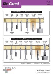
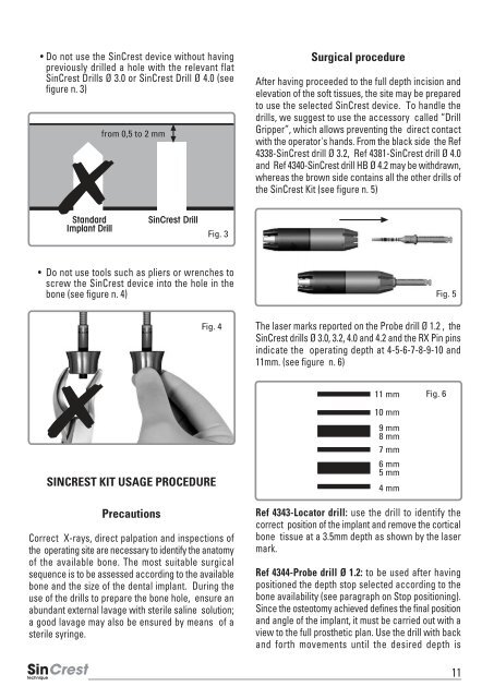
• Do not use <strong>the</strong> SinCrest device <strong>with</strong>out havingpreviously drilled a hole <strong>with</strong> <strong>the</strong> relevant flatSinCrest Drills Ø 3.0 or SinCrest Drill Ø 4.0 (seefigure n. 3)from 0,5 to 2 mmSurgical procedureAfter having proceeded to <strong>the</strong> full depth incision andelevation of <strong>the</strong> soft tissues, <strong>the</strong> site may be preparedto use <strong>the</strong> selected SinCrest device. To handle <strong>the</strong>drills, we suggest to use <strong>the</strong> accessory called “DrillGripper”, which allows preventing <strong>the</strong> direct contact<strong>with</strong> <strong>the</strong> operator's hands. From <strong>the</strong> black side <strong>the</strong> Ref4338-SinCrest drill Ø 3.2, Ref 4381-SinCrest drill Ø 4.0and Ref 4340-SinCrest drill HB Ø 4.2 may be <strong>with</strong>drawn,whereas <strong>the</strong> brown side contains all <strong>the</strong> o<strong>the</strong>r drills of<strong>the</strong> SinCrest <strong>Kit</strong> (see figure n. 5)StandardImplant DrillSinCrest DrillFig. 3• Do not use tools such as pliers or wrenches toscrew <strong>the</strong> SinCrest device into <strong>the</strong> hole in <strong>the</strong>bone (see figure n. 4)Fig. 5Fig. 4The laser marks reported on <strong>the</strong> Probe drill Ø 1.2 , <strong>the</strong>SinCrest drills Ø 3.0, 3.2, 4.0 and 4.2 and <strong>the</strong> RX Pin pinsindicate <strong>the</strong> operating depth at 4-5-6-7-8-9-10 and11mm. (see figure n. 6)11 mmFig. 610 mmSINCREST KIT USAGE PROCEDUREPrecautionsCorrect X-rays, direct palpation and inspections of<strong>the</strong> operating site are necessary to identify <strong>the</strong> anatomyof <strong>the</strong> available bone. The most suitable surgicalsequence is to be assessed according to <strong>the</strong> availablebone and <strong>the</strong> size of <strong>the</strong> dental implant. During <strong>the</strong>use of <strong>the</strong> drills to prepare <strong>the</strong> bone hole, ensure anabundant external lavage <strong>with</strong> sterile saline solution;a good lavage may also be ensured by means of asterile syringe.9 mm8 mm7 mm6 mm5 mm4 mmRef 4343-Locator drill: use <strong>the</strong> drill to identify <strong>the</strong>correct position of <strong>the</strong> implant and remove <strong>the</strong> corticalbone tissue at a 3.5mm depth as shown by <strong>the</strong> lasermark.Ref 4344-Probe drill Ø 1.2: to be used after havingpositioned <strong>the</strong> depth stop selected according to <strong>the</strong>bone availability (see paragraph on Stop positioning).Since <strong>the</strong> osteotomy achieved defines <strong>the</strong> final positionand angle of <strong>the</strong> implant, it must be carried out <strong>with</strong> aview to <strong>the</strong> full pros<strong>the</strong>tic plan. Use <strong>the</strong> drill <strong>with</strong> backand <strong>for</strong>th movements until <strong>the</strong> desired depth is11