Kit for the maxillary sinus lift with crestal approach - Osteogenics
Kit for the maxillary sinus lift with crestal approach - Osteogenics
Kit for the maxillary sinus lift with crestal approach - Osteogenics
- No tags were found...

Create successful ePaper yourself
Turn your PDF publications into a flip-book with our unique Google optimized e-Paper software.
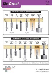
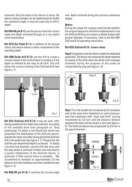
achieved. Only <strong>the</strong> head of <strong>the</strong> device is sharp. Nolateral cutting strength can be implemented to modify<strong>the</strong> osteotomy angle: it must be used only to drill indepth.Ref 4354-RX pin Ø 1.2: use <strong>the</strong> pins to check <strong>the</strong> correctangle and depth achieved through an x-ray and/orvisual examination.Ref 4379-Sin Probe Ø 1.2: in addition to <strong>the</strong> tactualcheck, this device allows a metric assessment of <strong>the</strong>operating depth.Ref 4380-Guide drill Ø 3.0: use <strong>the</strong> drill to create acoronal recess in <strong>the</strong> cortical layer to achieve a 2 mmdepth as defined by <strong>the</strong> stop on <strong>the</strong> drill. This drillallows <strong>the</strong> correct centring of <strong>the</strong> SinCrest Drill (seefigure n. 7).and depth achieved during <strong>the</strong> previous osteotomystages.Notice:During this stage <strong>the</strong> surgeon must decide whe<strong>the</strong>r<strong>the</strong> surgical sequence should be implemented to use<strong>the</strong> SinCrest Ø 4.0 so as to place a dental implant <strong>with</strong>greater diameter. If necessary, refer to <strong>the</strong> Ref 4381SinCrest Ø 4.0 operating instructions.Ref 4333-SinCrest Ø 3.0 - brown colourStep 0 Gradually screw <strong>the</strong> device inside <strong>the</strong> dedicatedguide hole. The device has achieved <strong>the</strong> depth obtainedby means of <strong>the</strong> drills when <strong>the</strong> white mark emergesminimally during <strong>the</strong> progress of <strong>the</strong> probe ascomparedto <strong>the</strong> grip (see figure n. 8).Step 02 mmFig. 8Fig. 7Ref 4337-SinCrest drill Ø 3.0: it may be used afterhaving positioned <strong>the</strong> depth stop selected accordingto <strong>the</strong> available bone (see paragraph on Stoppositioning). To obtain a non-flared hole which mayjeopardize <strong>the</strong> stabilization of <strong>the</strong> SinCrest device,operate <strong>the</strong> motor only after having placed <strong>the</strong> SinCrestdrill in <strong>the</strong> guide hole (see figure n. 7). Prepare <strong>the</strong> siteuntil <strong>the</strong> pre-determined depth is achieved. To obtaina precise hole diameter, use <strong>the</strong> drill only once until<strong>the</strong> stop stroke is achieved. Fur<strong>the</strong>r uses may lead toa poorer stabilization of <strong>the</strong> SinCrest device, inparticular if little vertical bone is available. Werecommend to maintain an approximately 2.0 mmdistance from <strong>the</strong> <strong>maxillary</strong> <strong>sinus</strong> floor membrane (seefigure n. 3).Step 1 Turn <strong>the</strong> handle anti-clockwise by1/2 revolutionand at <strong>the</strong> same time implement an axial pressure,start <strong>the</strong> osteotomy <strong>with</strong> “back and <strong>for</strong>th” turningmovements by 1/2 turn until <strong>the</strong> distance (0.5mm)between <strong>the</strong> tooth and <strong>the</strong> stroke is zero (see figure n.9). The SinCrest device has progressed by 0.5 mm in<strong>the</strong> apical direction.STROKE0,5 mmTOOTHFig. 9Ref 4356-RX pin Ø 3.0: it confirms <strong>the</strong> correct angle12