
Create successful ePaper yourself
Turn your PDF publications into a flip-book with our unique Google optimized e-Paper software.
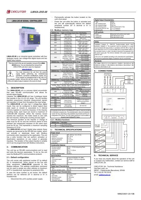
<strong>LM4A</strong>-<strong>2IO</strong><strong>2IO</strong>-M<strong>LM4A</strong>-<strong>2IO</strong>-M SIGNAL CENTRALIZER<strong>LM4A</strong>-<strong>2IO</strong>-M is an industrial signal centraliser with fouranalogue inputs, two voltage-free digital inputs and twodigital relay outputs.This document is the use and operation manual of the <strong>LM4A</strong>-<strong>2IO</strong>-M device. You can download the manual fromCIRCUTOR's web site in case it is misplaced:www.circutor.esYou must disconnect the unit from the powersupply before performing any maintenanceoperations, connection modifications, repairs, etc.If you suspect an operational fault in the unit or inits protection system, remove the unit from service. The designof the unit makes it easy to replace in the event of a fault.1.- DESCRIPTIONThe <strong>LM4A</strong>-<strong>2IO</strong>-M unit is a process signal concentratorthat uses RS-485 communication and allows forremote signal display.Likewise, the <strong>LM4A</strong>-<strong>2IO</strong>-M unit has 4 analogue inputsthat operate in the 0 to 20 mA range. The unit handlesstandard proportional industrial measurement signalsand operates in linear form throughout the input range.The <strong>LM4A</strong>-<strong>2IO</strong>-M unit also has 2 voltage-free digitalinputs; they can be configured to detect logical inputstate (open or closed) or associated to 2 internalmemory registers to count the impulses. In the impulsecounting mode, each input can record a maximum of4,294,967,295 impulses. When the memory recordreaches the maximum, the meter resets to zero withthe next impulse, starting the counting process again.The minimum duration of the impulse or change ofstate must be 50 ms and the minimum period of timebetween two subsequent impulses on the same inputmust be 50 ms. This represents a maximum samplingfrequency of 10 Hz.The <strong>LM4A</strong>-<strong>2IO</strong>-M unit has 2 digital relay outputs; theseoutputs are governed by the RS-485 bus master, whichcan activate or deactivate them with Modbuscommands when requested by the application. The unithas a write function that can perform activation ordeactivation operations on any output or generateimpulses. The duration of the output impulse is variableand it can be programmed with Modbus instructions.2.- COMMUNICATIONThe unit has an RS-485 communications port to readand write the device's parameters. To do so, the unituses the Modbus/RTU communications protocol.2.1.- Default configuration.The unit comes with peripheral number 97 by default(61 in hexadecimal). When placed on the bus withother equipment, <strong>LM4A</strong>-<strong>2IO</strong>-M responds to thisModbus address. The address modification commandcan be used to assign any other address (a maximumof FF in hexadecimal, equivalent to peripheral 255).In case the slave number is not known, the defaultaddress can be retrieved (97 in decimal or 61 inhexadecimal):- Disconnect the unit's auxiliary power supply- Permanently activate the button located on theunit's front panel- Power the unit while the button is activated andthe unit will automatically retrieve the defaultperipheral number (97 in decimal or 61 inhexadecimal).2.2.- Modbus memory map.MODBUS (Hex)000000010002000305000501050205032000MODBUS (Hex)1000Digital and Analogue Inputs Value / State ReadingMeter Value 1Meter Input 161 04 0000 0002 0000 0000...FFFF FFFF (Hex)Meter Value 2Meter Input 261 04 0002 0002 0000 0000...FFFF FFFF (Hex)Analogue input 1 Analogue input Value 161 04 0500 00010000...03FF (Hex)Analogue input 2 Analogue input Value 261 04 0501 00010000...03FF (Hex)Analogue input 3 Analogue input Value 361 04 0502 00010000...03FF (Hex)Analogue input 4 Analogue input Value 461 04 0503 00010000...03FF (Hex)Digital Input State 0000 1 and 2 deactivatedActivated = Closed (1) 0001 Input 1 activatedDeactivated = Open (0) 0002 Input 2 activated61 04 2000 0001 0003 1 and 2 activatedDigital Output Control Writing (Relay)Digital output Control (R) 0000 1 and 2 deactivatedActivated = Closed (1) 0001 Output 1 activatedDeactivated = Open (0) 0002 Output 2 activated61 10 1000 0001 02 0003 0003 1 and 2 activatedMODBUS (Hex) Impulse Digital Output Control Writing (Relay)Output Impulses (R) 0000 1 and 2 deactivated1500Activated = Closed (1) 0001 Output Impulse 1Deactivated = Open (0) 0002 Output Impulse 261 10 1500 0001 02 0003 0003 Output Impulse 1 & 2MODBUS (Hex) Impulse Duration Configuration Write2500Impulse duration 01 Duration 20 ms61 10 2500 0001 02 01 01 FF Duration 5100 msLow Byte - Relay 1 / High Byte - Relay 2 / Other values can be established (ms)The maximum duration of the impulse cannot exceed 5100 msMODBUS (Hex) Peripheral Configuration / Speed Writing3000Peripheral number 0001 Minimum value (001)61 10 3000 0001 02 0001 00FF Maximum (255)3001Transmission speed 0001 9600 bps61 10 3001 0001 02 0001 0002 19.200 bpsMODBUS (Hex) Version and Serial Number Reading35003501350235033504Device Version61 04 3500 0003Serial number61 04 3503 0002Format: “V1.10” values inASCII and the last byte isalways 0907 XXX XXXAll examples shown above on the Modbus/RTU memory map are providedfor information purposes only. The parameterisation values and peripheralnumber will vary, depending on the installation requirements and the priorconfiguration of the device. Two CRC bytes (checksum) must be added atthe end of each Modbus/RTU frame.2.2.1.- Modbus functionsMODBUS (Hex) Description04 Input records reading10 Writing of several records3.- TECHNICAL SPECIFICATIONSPower circuit- Single-phase:- Frequency:- Maximum consumption:- Working temperature:- Humidity withoutcondensation:Construction features- Enclosure material:- Protection degree:- Dimensions:- Weight:- Maximum operating height:Serial Interface- Type:- Transmission speed:- Data bits:- Parity:- Stop bit:85...265 Vac / 120...374 Vdc47...63 Hz3.5 VA-10...60 ºC5...95 %UL94 – V0 Self-extinguishing PlasticIP2093 x 71 x 58 mm180 g2000 mThree-wire RS-485 (A / B / GND)9,600 bps / 19,200 bps configurable8No parity1Digital Input Characteristics- Type:Voltage-free opto-insulated (dry contact)- Maximum activation current: 50 mAAnalogue Input Characteristics- Type:- Input range:- Resolution in points:- Input impedance:- Transducer resolution:Analogue current0...20 mA1.024 points100 Ω10 bitsDigital Output Characteristics- Type:- Max. operating power:- Max. operating voltage:- Max. switching current:- Electrical life (250 Vac / 5A):- Mechanical lifeLED symbols- Power:- Flashing RX:- Flashing TX:SafetyRelay750 VA250 VacWith resistive load Ie: 5 Aac3 x 10 4 operations2 x 10 7 operationsEquipment with auxiliary power supplyRS-485 Reception activityRS-485 Emission activityInstallation Category III / EN61010. Double-insulated electric shockprotection Category II. The equipment must be connected to a powercircuit protected with type gl fuses, in compliance with IEC 269, or type M,with values from 0.5 to 1A. It must be fitted with a circuit breaker switch oran equivalent device, in order to be able to disconnect the equipment fromthe power supply grid. The minimum diameter of the power supply cableshall be 1mm 2 .If the unit is not operated according to the manufacturer's specifications,the equipment guaranteed degree of protection may be compromised.StandardsIEC 60664, VDE 0110, UL 94, EN61010-1, EN55011, EN 61000-4-2, EN61000-4-3, 61000-4-11, EN 61000-6-4, EN 61000-6-2, EN 61000-6-1, EN61000-6-3, EN 61000-4-5, CE4.- CONNECTIONS5.- TECHNICAL SERVICEIf you have any doubts about the operation of the unitor suspect any malfunction, contact our service staff atCIRCUTOR, SACIRCUTOR, SA - Technical AssistenceVial Sant Jordi, s/n08232 – Viladecavalls (Barcelona), SPAINTel: (+34) 93 745 29 00email: sat@circutor.esM98233001-20-10B