Elektronik-Schutzschaltrelais E-1071-353 6
Elektronik-Schutzschaltrelais E-1071-353 6
Elektronik-Schutzschaltrelais E-1071-353 6
- No tags were found...

You also want an ePaper? Increase the reach of your titles
YUMPU automatically turns print PDFs into web optimized ePapers that Google loves.
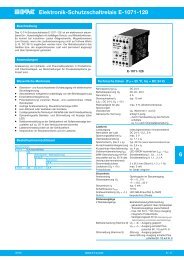
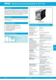
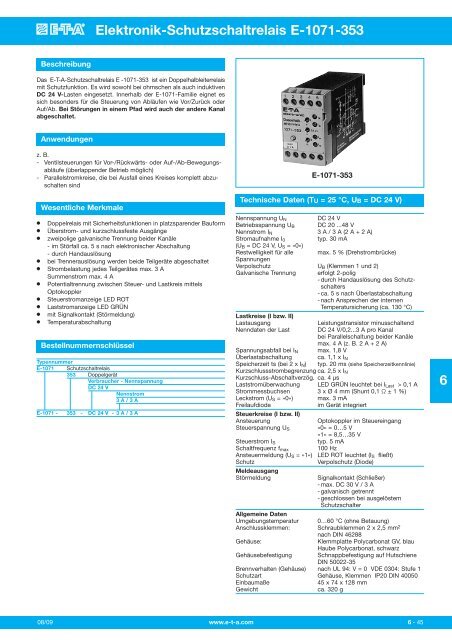
<strong>Elektronik</strong>-<strong>Schutzschaltrelais</strong> E-<strong>1071</strong>-<strong>353</strong>BeschreibungDas E-T-A-<strong>Schutzschaltrelais</strong> E -<strong>1071</strong>-<strong>353</strong> ist ein Doppelhalbleiterrelaismit Schutzfunktion. Es wird sowohl bei ohmschen als auch induktivenDC 24 V-Lasten eingesetzt. Innerhalb der E-<strong>1071</strong>-Familie eignet essich besonders für die Steuerung von Abläufen wie Vor/Zurück oderAuf/Ab. Bei Störungen in einem Pfad wird auch der andere Kanalabgeschaltet.Anwendungenz. B.- Ventilsteuerungen für Vor-/Rückwärts- oder Auf-/Ab-Bewegungsabläufe(überlappender Betrieb möglich)- Parallelstromkreise, die bei Ausfall eines Kreises komplett abzuschaltensind●●●●●●●●●●Wesentliche MerkmaleDoppelrelais mit Sicherheitsfunktionen in platzsparender BauformÜberstrom- und kurzschlussfeste Ausgängezweipolige galvanische Trennung beider Kanäle- im Störfall ca. 5 s nach elektronischer Abschaltung- durch Handauslösungbei Trennerauslösung werden beide Teilgeräte abgeschaltetStrombelastung jedes Teilgerätes max. 3 ASummenstrom max. 4 APotentialtrennung zwischen Steuer- und Lastkreis mittelsOptokopplerSteuerstromanzeige LED ROTLaststromanzeige LED GRÜNmit Signalkontakt (Störmeldung)TemperaturabschaltungBestellnummernschlüsselTypennummerE-<strong>1071</strong> <strong>Schutzschaltrelais</strong><strong>353</strong> DoppelgerätVerbraucher - NennspannungDC 24 VNennstrom3 A / 3 AE-<strong>1071</strong> - <strong>353</strong> - DC 24 V - 3 A / 3 AE-<strong>1071</strong>-<strong>353</strong>Technische Daten (TU = 25 °C, UB = DC 24 V)Nennspannung U NDC 24 VBetriebsspannung U B DC 20 ...48 VNennstrom I N 3 A / 3 A (2 A + 2 A)Stromaufnahme I 0typ. 30 mA(U B = DC 24 V, U S = »0«)Restwelligkeit für alle max. 5 % (Drehstrombrücke)SpannungenVerpolschutz U B (Klemmen 1 und 2)Galvanische Trennung erfolgt 2-polig- durch Handauslösung des Schutzschalters- ca. 5 s nach Überlastabschaltung- nach Ansprechen der internenTemperatursicherung (ca. 130 °C)Lastkreise (I bzw. II)LastausgangLeistungstransistor minusschaltendNenndaten der Last DC 24 V/0,2...3 A pro Kanalbei Parallelschaltung beider Kanälemax. 4 A (z. B. 2 A + 2 A)Spannungsabfall bei I N max. 1,8 VÜberlastabschaltung ca. 1,1 x I NSpeicherzeit ts (bei 2 x I N ) typ. 20 ms (siehe Speicherzeitkennlinie)Kurzschlussstrombegrenzung ca. 2,5 x I NKurzschluss-Abschaltverzög. ca. 4 μsLaststromüberwachung LED GRÜN leuchtet bei I Last > 0,1 AStrommessbuchsen 3 x Ø 4 mm (Shunt 0,1 Ω ± 1 %)Leckstrom (U S = »0«) max. 3 mAFreilaufdiodeim Gerät integriertSteuerkreise (I bzw. II)AnsteuerungOptokoppler im SteuereingangSteuerspannung U S »0« = 0…5 V»1« = 8,5…35 VSteuerstrom I Styp. 5 mASchaltfrequenz f max 100 HzAnsteuermeldung (U S = »1«) LED ROT leuchtet (I S fließt)SchutzVerpolschutz (Diode)MeldeausgangStörmeldungSignalkontakt (Schließer)- max. DC 30 V / 3 A- galvanisch getrennt- geschlossen bei ausgelöstemSchutzschalterAllgemeine DatenUmgebungstemperatur 0…60 °C (ohne Betauung)Anschlussklemmen: Schraubklemmen 2 x 2,5 mm 2nach DIN 46288Gehäuse:Klemmplatte Polycarbonat GV, blauHaube Polycarbonat, schwarzGehäusebefestigung Schnappbefestigung auf HutschieneDIN 50022-35Brennverhalten (Gehäuse) nach UL 94: V = 0 VDE 0304: Stufe 1Schutzart Gehäuse, Klemmen IP20 DIN 40050Einbaumaße45 x 74 x 128 mmGewichtca. 320 g608/09 www.e-t-a.com6 - 45
<strong>Elektronik</strong>-<strong>Schutzschaltrelais</strong> E-<strong>1071</strong>-<strong>353</strong>6FunktionsbeschreibungIm E-T-A <strong>Schutzschaltrelais</strong> E-<strong>1071</strong>-<strong>353</strong> lassen sich im Normalbetriebdie Lastausgänge zweier Kanäle unabhängig voneinander elektrischzu- und abschalten.Steuerkreise (I bzw. II)Liegt an den Eingangsklemmen (6 und 7 bzw. 10 und 7) eineSpannung, die größer ist als 8,5 V (= Steuersignal »1«), fließt sofort derSteuerstrom durch LED und Optokoppler. Dieser überträgt das Signalan den Laststromkreis und schaltet damit den Lasttransistor ein.Gleichzeitig geht dieses Signal als Zustandsmeldung an alle Überwachungsschaltungen.Die Eingangsschutzdiode verhindert Fehlerdurch Verpolung der Steuerspannung, die Konstantstromdiodebegrenzt die Ansteuerleistung.Lastkreise (I bzw. II)Der Laststromkreis schaltet entsprechend dem Steuersignal »0« oder»1«. Elektronische Schaltungen überwachen nun den Lastkreis aufFehler wie Überlast oder Kurzschluss. Bei Überlast oder Kurzschlussgreift die Überwachungsschaltung direkt ein, d. h. sie bewirkt dasAusschalten des Lasttransistors und die Auslösung des Schutzschalters.Diese Abschaltung des Ausgangstransistors erfolgt nach derSpeicherzeitkennlinie. Die Speicherzeit erhöht die Störsicherheit, sieverhindert unerwünschtes Abschalten bei kurzen Stromspitzen. DieSpeicherzeit ist keine konstante Größe, sondern verringert sich mitsteigendem Überstrom.Nach Ablauf der Speicherzeit (siehe Diagramm) sperrt derLastkreistransistor. Nach ca. 5 s löst der Trenner aus und schaltetdamit beide Lastkreise ab. Der gemeinsame Signalkontakt schließtund meldet die Störung. Nach Beseitigung der Störursache kanndurch Drücken des Trennerknopfes das Gerät wieder aktiviert werden.ZustandsmeldungenFrontseitig sind 4 LEDs (2xROT, 2xGRÜN) montiert, die den Geräte zu -stand signalisieren.LED ROTAnsteuerungsanzeige (I bzw. II)Diese LED leuchtet, wenn die Steuerspannung größer als 8,5 V ist undder Steuerstrom fließt.LED GRÜNStromflussanzeige (I bzw. II)Diese LED leuchtet, wenn der Laststrom größer 0,1 A ist.Wenn die rote LED leuchtet und die grüne LED nicht, liegt ein Fehlerder Last (zu hochohmig), in der Verdrahtung (Drahtbruch, schlechterKontakt) oder Überlast bzw. Kurzschluss vor.Zusätzlich sind 3 Strommessbuchsen (Ø 4 mm) frontseitig montiert.An diesen Buchsen lässt sich der Laststrom als Spannungsabfall aneinem 0,1 Ω Shunt, der sich im Laststromkreis (I bzw. II) befindet,messen.Speicherzeitkennlinie ts (TU = 25 °C)Zeit in ms100010020105I N 2BetriebszuständeBetriebszustand3Strombegrenzung4 5 x I N(theor. Überstromfaktor)Störungsfreier Kurzschluss DrahtbruchBetrieb der LastSteuereingang »0« »1« »1« »0« »1«LED ROT - 0 1 1 0 1SteuerstromLED GRÜN- 0 1 0 0 0LaststromüberwachungSignalkontakt offen offen geschlossen offen offenBemerkung Last Last beide Last-AUS EIN kreise getrennt1 - LED leuchtet0 - LED leuchtet nicht6 - 46www.e-t-a.com08/09
<strong>Elektronik</strong>-<strong>Schutzschaltrelais</strong> E-<strong>1071</strong>-<strong>353</strong>MaßbildAnschlussbild1 2 3 4 51 2 3 4 5Doppelhalbleiterrelais<strong>1071</strong> - <strong>353</strong>24 V3/3 AIMISt6 7 8 9 10+-+I0,1ΩIIIMISt7045 12473,2Doppelhalbleiterrelais<strong>1071</strong> - <strong>353</strong>24 V3/3 A+-+I0,1IIIMIStIMISt6 7 8 9 10Blockschaltbild+ 6rtI- 7gngn+ 10IIrt98+ 1- 2-0,1+4Trennerlogik3Logik--I K-I ges5-T max+0,1Last 1Last 2IIIKlemme:1 +U B (Betriebsspannung Plus: DC 20...48 V)2 - U B (Betriebsspannung Minus)3 Last (+) (führt +Potential) Achtung: nicht an Masse/–U B legen4 Last I (-)5 Last II (-)6 +U S (Steuerspannung I Plus: max. DC 35 V)7 -U S (Steuerspannung I, II Minus)8 Signalkontakt9 Signalkontakt10 +U S (Steuerspannung II Plus: max. DC 35 V)6<strong>1071</strong> - 3..Die zur Verfügung gestellten Informationen sind nach unserem Wissen genau und zuverlässig,jedoch übernimmt E-T-A keine Verantwortung für den Einsatz in einer Anwendung, dienicht der vorliegenden Spezifikation entspricht. E-T-A behält sich das Recht vor,Spezifikationen im Sinne des technischen Fortschritts jederzeit zu ändern. Maßänderungensind vorbehalten, bei Bedarf bitte neuestes Maßblatt mit Toleranzen anfordern. Maße, Daten,Abbildungen und Beschreibung entsprechen dem neuesten Stand bei Herausgabe diesesKataloges, sind aber unverbindlich! Änderungen sowie auch Irrtümer und Druckfehler vorbehalten.Die Bestellbezeichnung der Geräte kann von deren Beschriftung abweichen.08/09 www.e-t-a.com6 - 47
Solid State Remote Power Controller E-<strong>1071</strong>-<strong>353</strong>DescriptionThe E-T-A Solid State Remote Power Controller E-<strong>1071</strong>-<strong>353</strong> is a doublerelay with protective function both for resistive and inductive DC 24 Vloads. It is particularly suitable to control upward/downward andforward/backward movements. Failure of one channel will also causethe other channel to disconnect.Typical applications- Valve timing gears for forward/backward or upward/downwardmovements (overlapping operation is possible)- Parallel circuits which must be completely disconnected uponfailure of one of the circuits.Features● Small double relay with protective function● Overcurrent and short-circuit proof outputs● Two pole physical isolation of both channels- approx. 5 s after electronic disconnection of a fault- by manual release● Both part units are disconnected upon the isolator tripping● Current load of each unit: max. 3 A; total current max. 4 A● Electrical isolation between control and load circuit by means ofopto coupler● Control current indication by RED LED● Load current indication by GREEN LED● With auxiliary contact (fault indication)● Temperature disconnectionOrdering informationType No.E-<strong>1071</strong> SSRPC<strong>353</strong> double unitVoltage rating of loadDC 24 VCurrent rating3 A / 3 AE-<strong>1071</strong> - <strong>353</strong> - DC 24 V - 3 A / 3 A ordering exampleE-<strong>1071</strong>-<strong>353</strong>Technical data (T ambient = 25 °C, U S = DC 24 V)Voltage rating U NDC 24 VOperating voltage U S DC 20...48 VCurrent rating I N 3 A/3 A (2 A + 2 A)Current consumption typically 30 mA(U S = DC 24 V, U Contr = “0”)Residual ripple for all voltages max. 5 % (3 phase bridge)Reverse polarity protection U S (terminals 1 and 2)Physical isolation2-pole- by manual circuit breaker release- approx. 5 s after overloaddisconnection- upon thermal response(approx. +130 °C)Load circuits (I/II)Load outputNPN transistor, minus switchingLoad ratingDC 24 V/0.2...3 A per channelwith parallel duty of both channels:max. 4 A (e. g. 2 A + 2 A)Voltage drop at I Nmax. 1.8 VOverload disconnection approx. 1.1 x I NStorage time t S (at 2xI N ) typically 20 ms (see storage time curve)Short-circuit limitation approx. 2.5 x I NShort-circuit response delay approx. 4 μsLoad current monitoring GREEN LED lights at I load > 0.1 ACurrent measuring terminals 3 x 4 mm dia. (shunt 0.1 Ω ± 1 %)Leakage current (U Contr = “0”) max. 3 mAFree-wheeling diode integralControl circuits (I/II)Controlopto coupler in control inputControl voltage U Contr “0” = 0...5 V“1” = 8.5...35 VControl current I Contr typically 5 mASwitching frequency f max 100 HzControl signal (U Contr = “1“) RED LED lights (I Contr flowing)Protectionreverse polarity protection (diode)Signal outputFault indicationauxiliary contact (N/O)- max. DC 30 V/3 A- physically isolated- closed when the circuit breaker hastrippedGeneral dataAmbient temperature 0...+60 °C (without condensation)Terminalsscrew terminals 2 x 2.5 mm 2 toDIN 46288Housingclamping plate: polycarbonate GV, bluecover: polycarbonate, blackMounting symmetric rail to EN 50022-35Self-extinguishing properties to UL 94: V = 0; VDE 0304: grade 1Degree of protection IP20 housing, terminals(IEC 529/DIN 40050)Mounting dimensions 45 x 74 x 128 mmMassapprox. 320 g6Issue B www.e-t-a.com6 - 45
Solid State Remote Power Controller E-<strong>1071</strong>-<strong>353</strong>6Technical descriptionUnder normal operating conditions, the E-T-A SSRPC E-<strong>1071</strong>-<strong>353</strong>allows the connection or disconnection of the load outputs of twochannels independent of each other.Control circuits (I/II)The control current flows through the LED and the opto couplerimmediately a voltage higher than 8.5 V (= ^ control signal “1”) isapplied at the input terminals (6 and 7, or 10 and 7). The opto couplertransmits the signal to the load circuit, at the same time switching theload transistor on. This signal is transmitted as a status signal to allmonitoring circuits. The input protection diode protects the controlvoltage from incorrect polarization. Control current limitation isprovided by a constant current diode.Load circuits (I/II)The load circuit is switched ON or OFF according to the control signal(“0” or “1”), with electronic circuits monitoring the load circuit for faultssuch as overload or short-circuit. Should one of these faults occur, themonitoring circuitry will immediately react, causing the load transistorto disconnect and the circuit breaker to trip. Transistor disconnectionoccurs according to the storage time characteristics. The storage timeincreases noise immunity avoiding disconnection of non-harmfulpeaks such as those caused by inrush currents from lamp loadconnection. Storage time is not a constant quantity but is inverselyproportional to the overcurrent factor.After expiration of the storage time (see diagram) the load circuittransistor will become non-conductive. After approx. 5 s the isolatorwill switch off so as to disconnect the two load circuits. The commonauxiliary contact closes signalling the fault. After removal of the fault,the SSRPC can be reactivated by pushing the isolator button.Status outputsStatus indication is provided by 4 LEDs (2 x RED, 2 x GREEN).RED LEDON indication (I/II)The red LED indicates when the control voltage is higher than 8.5 V,with control current flowing.GREEN LEDCurrent flow indication (I/II)The green LED indicates when the load current is above 0.1 A.Faults such as too high a resistance, wire break, poor contact, oroverload/short-circuit, are available when only the red LED indicates.The SSRPC E-<strong>1071</strong>-<strong>353</strong> includes three current measuring terminals(4 mm dia.) on the front. These terminals provide for load currentmeasurement in terms of voltage drop at the 0.1 Ω shunt in the loadcircuit (I/II).Storage time characteristic curve t s (T A = 25 °C)time in ms100010020105I N 2Operating modes3current limitation4 5 x I N(theoretical overcurrent factor)Operating status Fault-free Short-circuit Wire breakoperation on the loadControl input “0” “1” “1” “0” “1”RED LED - 0 1 1 0 1control currentGREEN LED - 0 1 0 0 0Load current monitoringAuxiliary contact open open closed open openRemarks load load both load circuitsOFF ON disconnected1 - LED indicates0 - LED does not indicate6- 46www.e-t-a.comIssue B
Solid State Remote Power Controller E-<strong>1071</strong>-<strong>353</strong>DimensionsTerminal selection1 2 3 4 51 2 3 4 5Doppelhalbleiterrelais<strong>1071</strong> - <strong>353</strong>24 V3/3 AIMISt6 7 8 9 10+-+I0.1ΩIIIMISt702.7645 1241.774.8873.22.88Doppelhalbleiterrelais<strong>1071</strong> - <strong>353</strong>24 V+-+IMIISt0.1ΩIMIIISt6 7 8 9 10This is a metric design and millimeter dimensions take precedence ( mm )inchBasic circuit diagramred+ 6I- 7greengreen+ 10IIred9isolatorlogic8+ 1- 20.1 Ω+-43logic--I K-I total5-T maxload 1load 2+0.1 ΩIIITerminal1 operating voltage + U S : DC 20...48 V2 operating voltage -U S3 load (+) (carrying plus potential)CAUTION: Do not connect to GND/-U S4 load I (-)5 load II (-)6 control voltage I +U Contr : max. DC 35 V7 control voltage I, II -U Contr8 auxiliary contact9 auxiliary contact10 auxiliary voltage II +U Contr : max. DC 35 V6<strong>1071</strong> - 3..All dimensions without tolerances are for reference only. In the interest of improved design,performance and cost effectiveness the right to make changes in these specifications withoutnotice is reserved. Product markings may not be exactly as the ordering codes. Errors andomissions excepted.Issue B www.e-t-a.com6 - 47