Elektronik-Schutzschaltrelais E-1071-073 6
Elektronik-Schutzschaltrelais E-1071-073 6
Elektronik-Schutzschaltrelais E-1071-073 6
- No tags were found...

You also want an ePaper? Increase the reach of your titles
YUMPU automatically turns print PDFs into web optimized ePapers that Google loves.
<strong>Elektronik</strong>-<strong>Schutzschaltrelais</strong> E-<strong>1071</strong>-<strong>073</strong>MaßbildAnschlussbild1 2 3 4 51 2 3 4 5Halbleiterrelais<strong>1071</strong> - <strong>073</strong>20 … 48 V3 AMELDERISt IMINShunt0,1 + -6 7 8 9 10457012473,2Halbleiterrelais<strong>1071</strong> - <strong>073</strong>20 … 48 V3 AMELDERI St I MINShunt0,1 +-6 7 8 9 10BlockschaltbildgeDC 8,5 … 35 V DC 20 … 48 V+ 67 -Steuereingang+ 12 -Trenner8 93R L4Shunt0,1Klemme:1 +U B (Betriebsspannung Plus: DC 20...48 V)2 - U B (Betriebsspannung Minus)3 Last (+)4 Last (-)5 frei6 +U S (Steuerspannung Plus: max. DC 35 V)7 -U S (Steuerspannung Minus)8 Signalkontakt9 Signalkontakt10 freign<strong>Elektronik</strong>I MIN<strong>1071</strong> - <strong>073</strong>6Die zur Verfügung gestellten Informationen sind nach unserem Wissen genau und zuverlässig,jedoch übernimmt E-T-A keine Verantwortung für den Einsatz in einer Anwendung, dienicht der vorliegenden Spezifikation entspricht. E-T-A behält sich das Recht vor,Spezifikationen im Sinne des technischen Fortschritts jederzeit zu ändern. Maßänderungensind vorbehalten, bei Bedarf bitte neuestes Maßblatt mit Toleranzen anfordern. Maße, Daten,Abbildungen und Beschreibung entsprechen dem neuesten Stand bei Herausgabe diesesKataloges, sind aber unverbindlich! Änderungen sowie auch Irrtümer und Druckfehler vorbehalten.Die Bestellbezeichnung der Geräte kann von deren Beschriftung abweichen.08/09 www.e-t-a.com6 - 35
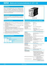
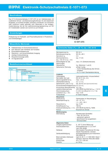
Solid State Remote Power Controller E-<strong>1071</strong>-<strong>073</strong>DescriptionThe E-T-A Remote Power Controller E-<strong>1071</strong>-<strong>073</strong> is an electronicON/OFF control module with protective functions and is suitable forresistive and inductive loads such as solenoids in rolling mills andother large plant applications. It is specifically used in plantmodernization where the load circuit supply should be maintained atDC 24 V.●●●●●●●Typical applicationsControl of hydraulic and pneumatic systems in production lines andchemical plants.FeaturesSolid-state relay with protective functionsSolid-state switching avoids contact arcing and weldingInrush current limitationOverload and short-circuit proof outputLow control powerControl current indication by LEDAuxiliary contactOrdering informationType No.E-<strong>1071</strong> SSRPC<strong>073</strong> with signal outputVoltage rating of loadDC 24 VCurrent rating3.0 AE-<strong>1071</strong> - <strong>073</strong> - DC 24 V - 3.0 A ordering exampleE-<strong>1071</strong>-<strong>073</strong>Technical data (Tambient = 25 °C, US = DC 24 V)Voltage rating U NDC 24 VOperating voltage U S DC 20...48 VCurrent rating I N3 ACurrent consumption typically 17 mA(U S = DC 24 V, U Contr = “0”)Residual ripple for all voltages max. 5 % (3 phase bridge)Reverse polarity protection U S (terminals 1 and 2)Physical isolation2-pole- by circuit breaker hand release- approx. 5 s after overloaddisconnectionLoad circuitLoad outputNPN transistor, minus switchingLoad ratingDC 24 V/0.2...3 AVoltage drop at I Nmax. 1.75 VOverload disconnection approx. 1.1 x I NStorage time t S (at 2xI N ) typically 20 ms (see storage time curve)Short-circuit limitation approx. 2.5 x I NShort-circuit response delay approx. 4 μsLoad current monitoring GREEN LED (lights at I load > 0.2 A)Current measuring terminals 2 x 2 mm dia. (0.1 Ω shunt ± 1 %)Leakage current (U Contr = “0”) max. 3 mAFree-wheeling diode integralControl circuitControlopto coupler in control inputControl voltage U Contr “0” = 0...5 V“1” = 8.5...35 VControl current I Contr typically 5 mASwitching frequency f max 100 HzControl signal (U Contr = “1”) YELLOW LED lights (IS flowing)Protectionreverse polarity protection (diode)Signal outputFault indicationauxiliary contact (N/O)- max. DC 30 V/3 A- physically isolated- closed with the circuit breakertrippedGeneral dataAmbient temperature 0...+60 °C (without condensation)Terminalsscrew terminals 2 x 2.5 mm 2 toDIN 46288Housingclamping plate: polycarbonate GV, bluecover: polycarbonate, blackMounting symmetric rail to EN 50022-35Self-extinguishing properties to UL 94: V = 0; VDE 0304: grade 1Degree of protection IP20 housing, terminals(IEC 529/DIN 40050)Mounting dimensions 45 x 74 x 128 mmMassapprox. 240 g6Issue B www.e-t-a.com6 - 33
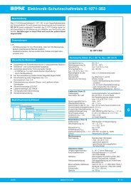
Solid State Remote Power Controller E-<strong>1071</strong>-<strong>073</strong>6Solid State Remote Power Controller E-<strong>1071</strong>-<strong>073</strong>In principle, the E-T-A SSRPC E-<strong>1071</strong>-<strong>073</strong> operates like conventionalelectro-mechanical relays, with additional protective and signalfunctions. The control input replaces the magnetic coil and the powertransistor replaces the main contact.Control circuitThe control current flows through the LED and the opto couplerimmediately a voltage higher than 8.5 V (= control signal “1”) isapplied at the input terminals (6 and 7). The opto coupler transmits thesignal to the load circuit, at the same time switching the loadtransistor on. This signal is transmitted as a status signal to allmonitoring circuits. The input protection diode protects the controlvoltage from incorrect polarization. Control current limitation isprovided by a constant current diode.Load circuitThe load circuit is switched ON or OFF according to the control signal(“0” or “1”), with electronic circuits monitoring the load circuit for faultssuch as overload or short-circuit. Should one of these faults occur, themonitoring circuitry will immediately react, causing the load transistorto disconnect and the circuit breaker to trip. Transistor disconnectionoccurs according to the storage time characteristics. The storage timeincreases noise immunity avoiding disconnection of non-harmfulpeaks such as those caused by inrush currents from lamp loadconnection. Storage time is not a constant quantity but is inverselyproportional to the overcurrent factor.Status indicationStatus indication is provided by 2 LEDs (yellow and green) on the frontof the housing.YELLOW LED = correct control voltageThe LED indicates when the control voltage ishigher than 8.5 V, with control current flowing.GREEN LED = correct load currentThe green LED indicates when the load current ishigher than 0.2 A.Faults such as too high a load resistance, wire break, poor contact, oroverload/short-circuit, are available when only the yellow LEDindicates. SSRPC E-<strong>1071</strong>-<strong>073</strong> includes two current measuringterminals (2 mm dia.) on the front. These terminals provide for loadcurrent measurement in terms of voltage drop at the 0.1 Ω shunt in theload circuit.Storage time characteristic curve t s (T A = 25 °C)time in ms100010020105I N 2Operating modes3current limitation4 5 x I N(theoretical overcurrent factor)Operating status Fault-free Short-circuit Wire breakoperation on the loadControl input U Contr “0” “1” “1” “0” “1”YELLOW LED - 0 1 1 0 1control currentGREEN LED - 0 1 0 0 0load current monitoringAuxiliary contact open open closed open openRemarks load load circuit breakerOFF ON tripped1 - LED indicates0 - LED does not indicate6- 34www.e-t-a.comIssue B
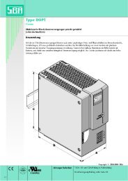
Solid State Remote Power Controller E-<strong>1071</strong>-<strong>073</strong>DimensionsTerminal selection1 2 3 4 51 2 3 4 5Halbleiterrelais<strong>1071</strong> - <strong>073</strong>20 … 48 VMELDERISt IMINShunt0.1Ω + -702.7673.22.88Halbleiterrelais<strong>1071</strong> - <strong>073</strong>MELDERI St I MIN6 7 8 9 10451.771244.8820 … 48 V3 AShunt0.1Ω +-6 7 8 9 10This is a metric design and millimeter dimensions take precedence ( mm )inchBasic circuit diagramDC 8.5 … 35 V DC 20 … 48 V+ 67 -+ 12 -8 93R L4Terminal1 operating voltage +U S : DC 20...48 V2 operating voltage -U S3 load (+)4 load (-)5 not used6 control voltage +U Contr : max. DC 35 V7 control voltage -U Contr8 auxiliary contact9 auxiliary contact10 not usedyellowcontrolinputisolatorShunt0.1 ΩgreenelectronicsI MIN<strong>1071</strong> - <strong>073</strong>6All dimensions without tolerances are for reference only. In the interest of improved design,performance and cost effectiveness the right to make changes in these specifications withoutnotice is reserved. Product markings may not be exactly as the ordering codes. Errors andomissions excepted.Issue B www.e-t-a.com6 - 35